Embed Size (px)
Citation preview

Fingerprint Image Enhancement Method
Using Directional Median Filter
Chaohong Wu, Zhixin Shi ∗ and Venu Govindaraju
Center for Unified Biometrics and Sensors
Department of Computer Science and Engineering
State University of New York at Buffalo
Buffalo, NY 14260
Abstract
The performance of any fingerprint recognizer highly depends on the fingerprintimage quality. Different types of noises in the fingerprint images pose greater dif-ficulty for recognizers. Most Automatic Fingerprint Identification Systems (AFIS)use some form of image enhancement. Although several methods have been de-scribed in the literature, there is still scope for improvement. In particular, effectivemethodology of cleaning the valleys between the ridge contours are lacking. Weobserve that noisy valley pixels and the pixels in the interrupted ridge flow gapare “impulse noises”. Therefore, this paper describes a new approach to fingerprintimage enhancement, which is based on integration of Anisotropic Filter and direc-tional median filter(DMF). Gaussian-distributed noises are reduced effectively byAnisotropic Filter, “impulse noises” are reduced efficiently by DMF. Usually, tra-ditional median filter is the most effective method to remove pepper-and-salt noiseand other small artifacts, the proposed DMF can not only finish its original tasks,it can also join broken fingerprint ridges, fill out the holes of fingerprint images,smooth irregular ridges as well as remove some annoying small artifacts betweenridges. The enhancement algorithm has been implemented and tested on fingerprintimages from FVC2002. Images of varying quality have been used to evaluate theperformance of our approach. We have compared our method with other methodsdescribed in the literature in terms of matched minutiae, missed minutiae, spuriousminutiae, and flipped minutiae(between end points and bifurcation points). Exper-imental results show our method to be superior to those described in the literature.
Key words: Fingerprint, Directional median filter, Image enhancement, Chaincode
∗ Corresponding authorEmail address: [email protected] (Zhixin Shi).
Preprint submitted to Elsevier Science 18 February 2004
1 Introduction
More recently, significant increasing need for biometric technology in forensicand non-forensic applications invite a lot of efforts and researches for im-proving current biometric systems. Fingerprint is the first biometric systemadopted by law enforcement agencies, and now is also the most widely usedsystem. Most AFISs are based on minutiae matching. The major minutiae fea-tures used by AFISs, are endings and bifurcations, which represent termina-tions and intersections of fingerprint ridge line flows. Although the automaticfingerprint recognition and identification have wide and long practical appli-cation, there still exists a lot of challenging and established image processingand pattern recognition problems[10].
Fingerprint image quality is of much importance to achieve high performancein Automatic Fingerprint Identification System(AFIS). Several researches [4,6,7,2,17]have proposed some enhancement techniques to this end. Enhancement of fin-gerprint images can be performed on either binary ridge images or direct grayimages. Binarization before enhancement will generate more spurious minu-tiae structures and lose some valuable original fingerprint information, it alsoposes more difficulties for later enhancement procedure. Therefore, most en-hancement algorithms are performed on gray images directly.
Hong and Jain [7] have shown that ridges and valleys in a gray fingerprintimage, forms a sinusoidal-shaped plane wave which possesses a clearly-definedfrequency and orientation. They described an approach using Gabor filterswhich can adaptively improve the clarity of fingerprint image ridges and val-leys by the local ridge orientation and frequency. Greenberg [4] has improvedHong’s [7] algorithm by using a unique anisotropic filter, which utilized onlyorientation information instead of both local ridge orientation and local fre-quency information. Yang [17] modified Hong’s method by discarding the inac-curate prior sinusoidal plane wave assumption, the single period of frequencydomain in Hong’s [7] method is substituted by two different frequencies, whichbest reflects the texture features of fingerprint image, furthermore, parame-ter selections in this modified algorithm is image-independent. Almansa [1]used diffusion techniques which included two mechanisms: (1)shape-adaptedsmoothing based on second moment descriptors and (2)automatic scale selec-tion based on normalized derivatives. The shape adaptation procedure allowsinterrupted ridges to be connected without destroying essential singularitiessuch as branching points and enforces continuity of their directional fields,and scale-selection procedure provides continuous and reliable estimate of thelocal distance between ridges. Tico [15] proposed a novel approach to finger-print image enhancement, the method calculates a binary representation ofthe fingerprint pattern based on the sign of second directional derivative ofthe digital images, the positive second directional derivative in the image will
2

be detected as fingerprint ridge regions.
This paper proposes a composite filter which integrates the advantages of bothdirectional median filter(DMF) and aniostropic filter, the enhancement perfor-mance outperforms Greenberg [4] filter method in joining interrupted ridgesand cleaning up the fingerprint valleys. The paper is organized as follows. Theoverview of proposed method will be addressed in Section 2. In Section 3, wepresent the technical details for enhancement procedure, including fingerprintbinarization method, orientation estimation, etc. The ridge contour followingevaluation measure based on chain-code will be discussed in Section 4. Exper-imental results and discussion will be presented in Section 5. We will draw ourconclusions in Section 6.
2 Overview of the Proposed Approach
The Fingerprint images either acquired by ink or scan may include a variety ofnoises causing ridge breaks, inter-ridges bridges, [16]. Reducing noises, healinginterrupted ridges, cleaning up ridge valleys and increasing the contrast be-tween ridges and valleys in the gray-scale fingerprint images are major tasks ofenhancement and restoration techniques. O’Gorman [2] and Nickerson(1989)designed their spatial domain filter based on smoothed local ridge directions.In frequency domain, Sherlock [14] proposed a fingerprint denoising methodbased on directional Fourier domain filtering. Willis [16] also described a FFT-based fingerprint image enhancement algorithm, his method could achievepatching in holes and separating incorrectly joined ridges. Hsieh [8] proposedan effective wavelet-based method for enhancement of fingerprint image, whichutilized both local orientation characteristic and global texture.
These enhancement methods (either in frequency domain or in spatial domain)could not meet the needs for real-time AFIS in improving valley clarity andridge flow continuity. The performance of most enhancement techniques relyheavily on the local ridge orientation. In this paper, we propose an integratedmethod, which utilizes both the adavantages of anisotropic filter and direc-tional median filter. The fingerprint images are first convolved with anisotropicfilter, and then are filtered by DMF. The pore in fingerprint ridge is completelyremoved (currently, pore features does not have practical application perspec-tives because it requires very high quality fingerprint images), small to mediumartifacts are almost cleared out, as well as broken ridges in most clear regionsare perfectly joined. The following two subsection will discuss those two filtersin detail.
3

2.1 Aniostropic Filter
Aniostropic filter plays similar role in reducing Gaussian-like noise as Gaborfilter in Hong’s [7] work. Greenberg [4] modified anisotropic filter by shapingthe filter kernel to process fingerprint image. It is essentially adapting filtershape to the local features (local intensity orientation) of fingerprint image.The general form of the anisotropic filter can be described as follows:
H(x0, x) = V + Sρ(x − x0)exp
{
−
[
((x − x0) · n)2
σ21(x0)
+((x − x0) · n⊥)2
σ22(x0)
]}
Where V and S are parameters for adjusting phase intensity and impact ofneighborhood, σ2
1(x0) and σ22(x0) controls the shape of the filter kernal, n and
n⊥ are mutually normal unit vectors and n is along the direction of ridgeline, ρ meets the condition ρ(x) = 1 when |x| < r, and r is the maximumsupport radius. In our experiments, V and S are set to −2 and 10 respectively,ρ2
1(x0) = 2 and ρ22(x0) = 4 so that the Gaussian-shape is created with a 1 : 2
ratio between the two kernal axes.
2.2 Directional Median Filter
According to Gonzalez [5]and Shapiro [13] median filter is performed as replac-ing a pixel with the median value of the selected neighbourhood. In particular,the median filter performs well at filtering outlier points while leaving edgesintact. The two-dimensional(2−D) standard median filter is defined as follows:
Definition 1 Given a gray-level image IM of size M×N with random impulse
noise distribution n, the observation OIM of original image is defined as,
OIM = IM + n
A median filter mask with suitably pre-selected window W of size (2k + 1) ×(2l + 1) operates on the position OIM(i, j), such that
Y (i, j; W ) = Median {OIMi−k,j−l, ..., OIMi,j , ..., OIMi+k,j+l}
where i = 1, ...,M, j = 1, ..., N , Y is the filtered output.
In fingerprint image processing, the standard median filter with rectangletopology appears to be difficult in achieving significant results in terms ofnoise reduction and image restoration. Even worse, filtering using standard
4

0
1
2
34
5
6
7
Fig. 1. Orientation of Fingerprint Ridge Flow
O
(0)
O
O
O O
O
O
O
O
O
X
O
O
O
O O
O O
O O
O
O
(1) (2) (3)
O
O
X
O
O O
(4)
X
O O
O O
OX
O O
O
O
O X
O
O
O
O
O
X
OO
O
(5)
O O
OXO
OOO
OO X
O OO
O
O
O
O
OOO
O
(6) (7)
Fig. 2. Eight directional templates, following orientation definitions
median filter could not only break up complete bifurcation minutiae due toorientation uncertainty surrounding it, but also generate some annoying arti-facts which lead to false minutiae. because the fingerprint images possess theunique ridge flow-like pattern with orientations changing slowly and smoothly.Actually, the ridges and valleys in a fingerprint image alternate in a relativelystable frequency, flowing in a local constant direction [12]. Assume that thepixels in the broken ridge gap are in the rectangle with the width of about 3pixels and the length of about 5-7 pixels, and the long side of the rectangleis in parallel with the local ridge direction. Clearly, the broken ridge gap pix-els can be considered as “impulse noises” in this confined rectangular region.Similarly, noises, which are in the rectangle region of the valleys with the longside being in parallel to the local ridge direction, can also be regarded as “im-pulse noises”. Therefore, the adaptive median filter with the same directionas local ridge can effectively reduce these “impulse noises”. Before the DMFis defined, the eight orientations of fingerprint ridge flow structure is definedas shown in Figure 1, the corresponding directional templates are describedin Figure 2.
Based on the defined eight directions, the shapes of directional median filtersare drawn accordingly. In this paper, the optimum window size of median filteris set to 9 based on empirical data. Obviously, the DMFs can preserve moredetails by introducing filters being locally adaptive to coherent flow fields.
5

Therefore, the proposed directional median filter(DMF) is defined as follows:
Definition 2 Eight Directional median filter templates with suitably pre-selected
window size W adopt different flow-like topological shapes, following their re-
spective orientations. When one point in the image is over the focus point of
the template kernal with the same orientation, the chosen median filter con-
volves with the current point, it generates W input samples,i.e., IM1, ..., IMW
in the specified window. Then, the output of the median filter is given by
Y (i, j; W ) = Median {IM1, ..., IMW}
The length of filter windows must be carefully chosen so that filtering canachieve optimal results. Too small a window might fail to reduce noise ade-quately, too large a window might produce unnecessary distortions or artifacts.Also directional median filter shapes must follow local orientations appropri-ately, and select more relative points to enhance ridge-flow continuity. Obvi-ously, the window size should be selected based on the image features. DMFpossesses recursive property. The DMF window of size W replaces some ofthe old input samples with some previously derived output samples. With thesame amount of operations, the DMFs with recursive feature usually providebetter smoothing capability and completion of interrupted ridges.
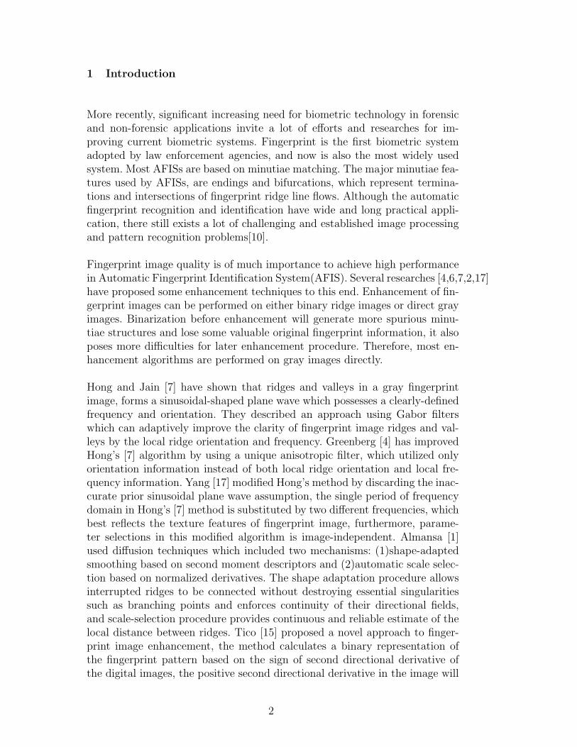
The properies of DMFs can be discussed with help of Figure 3,4 and 5. Fig-ure 3 shows three-dimension shapes of the Gabor filter. Clearly, Gabor filterconsiders the frequency and orientation of the images simultaneously [7], Ga-bor function is a Gaussian modulated sinusoid. Gabor filter is essentially abandpass filter with a calculable frequency and bandwidth determined by thestandard deviations of Gaussian envelope. The coefficient weights of the Ga-bor filter will reflect greater emphasis on the orientation flow of fingerprintimage, filtering can eliminate efficiently the noises with Gaussian distribution.However,the Gaussian-distribution noise model can not exactly represent thenoise model in the fingerprint image, as a matter of fact, pepper-salt noise,smudge in the valleys, interrupted ridge lines can not explained by Gaussianmodel at all. Any single noise model appears too simple to explain fingerprintimage noise. Our proposed adaptive median filter eliminate efficiently noisesin the valleys. Figure 4 demonstrates how the noises of medium size betweenthe adjacent ridge lines can be removed. In Figure 5, one hole with the size offour pixels can be filled out completely, it saves a lot of post-processing worksin removing false minutiae. Completion of broken fingerprint ridge flow linesusing DMFs can be illustrated similarly.
6

-10-5
05
10-10
-5
0
5
10
-4-3-2-1012345
(a)
-10
-5
0
5
10 -10-5
05
10
-4-3-2-1012345
(b)
Fig. 3. View of Gabor filter from (a)front and (b)side
Ridge L
ine
Directi
onal_
Med
ian T
empla
te
Noise
Fig. 4. Noises between the ridgelines
3 Fingerprint Image Enhancement Procedure
The restored fingerprint images will be more suitable than the original imagesfor visual examination and/or automatic feature extraction[9]. The fingerprintimage is first normalized [7] to reduce the variations of gray-level values alongthe ridges and valleys, the orientation fields are computed based on chain-code,the region of interest are then segmented from background using the methoddescribed by Ratha [12], the segmented fingerprint images are filtered by the
7
56 55
56 54 54 56 56
56 54 565654
55
55
56 55
545554 255
25554 55 255
255 54
5654 54
55545656
O O
O
54 56 55 56 54 56
56 54 54 56 56 55
54 55 55 56
55
54 54
56 56
54
OXO
O
O
56 54 55 55 54
56 55 55 54 56 54
56 56 54 54 55 54
O
(a) (b)
(c)
Fig. 5. Filling out the hole in fingerprint image. (a)image with one hole, (b)Mediantemplate with the same direction as the ridge, (c) filtered image
composite filter which is described in the section 2, the filtered images canbe binarized adaptively, finally the ridge contour following algorithm (section4) is utilized to extract endings and bifurcations minutiae, and filtering per-formance and efficiency are evaluated correspondingly. In the following twosubsections, the specific methods in this paper for orientation computationand binarization are explained in detail.
3.1 Orientation estimation
Orientation calculation is critical for fingerprint image enhancement and restora-tion in both frequency and spatial domain. Without exception, the computa-tion of the orientation image in the proposed algorithm will affect directly theenhancement efficiency. In the current literature, most of the fingerprint clas-sification and identification processes calculate the local ridge orientation ofthe fixed-size block instead of each pixel. The most popular approach is basedon binary image gradients [12,7],other approaches have been proposed in dif-ferent research groups [1,2,6]. An innovative computational method, based onchaincode, was proposed in our lab[3]. Chaincode is a lossless representation ofgray-level image in terms of image recovery. The chaincode representations offingerprint image edges capture not only boundry pixel information, but alsothe counter-clockwise ordering of those pixels in the edge contours. There-fore, it is convenient to calculate direction for each boundary pixel. In ourcalculation, end points and singular points, which are detected by the ridgeflow following method (section 4 Objective Evaluation Measures), are not usedfor computation of ridge flow orientation in the fingerprint images. Also thecomponents with chaincode elements less than 20 are regarded as noises and
8

excluded for orientation computations. The computation procedure can beoutlined as follows,
(1) Each image is divided into 15 × 15 pixel blocks.(2) In each block, frequencies F [i], i = 0...7 for eight directions are calculated.
Average frequency can be easily computed. Then the difference betweenthe frequency for each direction and average frequency can be calculated.
(3) Standard Deviation for eight directions is calculated. If the Value of cal-culated Standard Deviation is larger than a threshold, the direction withmaximum frequency will be regarded as dominant directions, otherwise,weighted average direction is computed as dominant direction.
The Standard deviation of the orientation distribution in a block is used todetermine the quality of the ridges in that block, and the quality measure ofthe whole fingerprint image can also be determined and classified into sev-eral classes. Each block direction will be smoothed based on the surroundingblocks. direction inconsistancies of some blocks will be corrected by simplerules. For example, for the block of interest, the directions of its left and rightblock are the same, current block will take the direction of its left block. Thismethod can get correct ridge orientations even for very noisy images.
3.2 Adapative Binarization Method
The fingerprint images possess ridge flow patterns with slowly changes in di-rections. They may have various grey-level values due to non-uniformity ofthe ink intensity, non-uniform contact with the sensors by users or changes inillumination and contrast during image acquisition process. Obviously, Globalthresholding method fails to create good quality binary images for furtherfeature extractions. In Greenberg’s work [4],adaptive thresholding is used tobinarize fingerprint images, binarization depends on the comparison result ofgrey-level value of each pixel with local mean. In this paper, we propose anadaptive binarization method based on Clustering of background and fore-ground pixels, i.e., Otsu algorithm [11]. Otsu’ method selects the optimalthreshold by minimizing the within-class variance of the two groups of pixelsseparated by the thresholding operator. The local block size is set to 23× 23.
4 Objective Evaluation Measures
To extract efficiently minutiae features from binarized fingerprint images, anew algorithm, called ridge contour following procedure, is proposed in ourlab to detect the minutiae starting from the thick-ridges in the binary image
9
P_in
P_out
(i) left turn
P_in
P_out
(ii) right turn
Thresholding line(x2,y2)
(x1,y1)
(x1,y1)
(x2,y2)
θ
θ
(a) (b)
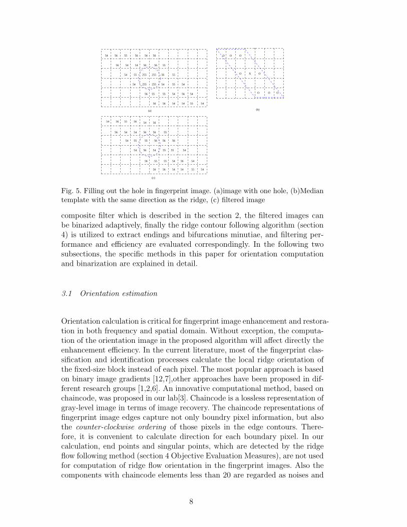
Fig. 6. (a) Minutia location on chaincode. (b) The distance between the thresholdingline and the y-axis gives a threshold for determining a significant turn.
instead of utilizing a conventional thinning process. As a matter of fact, thin-ning process could not only create spurious minutiae due to varying ridge-linethickness, but also be time-consuming. The details of ridge contuor followingalgorithm are described in detail in [3], here we provide simple introductionfor evaluation of enhancement performance.
The ridge contours of fingerprint images can be consistently traced in a counter-clock-wise fashion, see Figure 5(a). Two types of point clusters where eithera sharp left turn or a sharp right turn is run across, the two correspondingtypes of minutiae: a ridge ending and a bifurcation can be determined andmarked, respectively. To determined the significant left and right turning con-tour points clusters, vectors Pin leading in to the candidate point P from itsprevious neighboring contour points and Pout going out of P to several subse-quent contour points are computed. These vectors are normalized as the waysin Figure 5(b). The turning direction is determined by the sign of
S(Pin, Pout) = x1y2 − x2y1
S(Pin, Pout) > 0 indicates a left turn and S(Pin, Pout) < 0 indicates a right
turn. significant turns can be determined by
x1y1 + x2y2 < T
5 Experiment Results and Discussion
The enhancement algorithm described above has been implemented and testedon fingerprint images from FVC2002. The images of varying quality are usedto evaluate the performance of our algorithm. For a typical fingerprint, theresults of orientation field, the binary fingerprint images filtered by anisotropicfilter and proposed filter as well as the detected minutiae features are shown
10
(a) (b)
(c) (d)
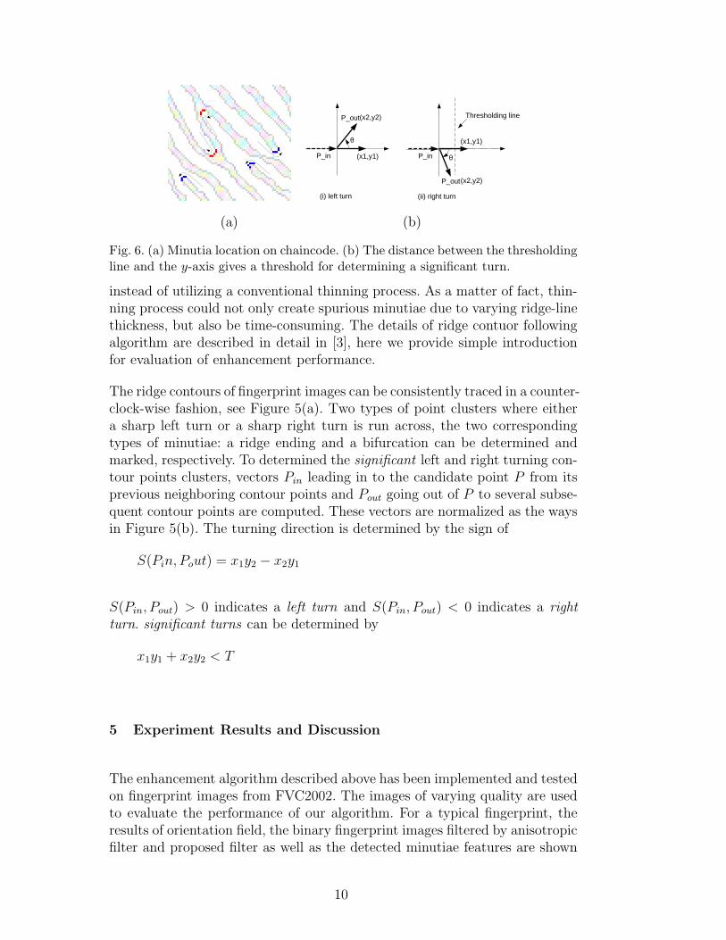
Fig. 7. (a)Original Fingerprint image. (b)orientation field. (c)The binarization offiltered image by Anisotropic filter. (d)The binarization of filtered image by theproposed filter.
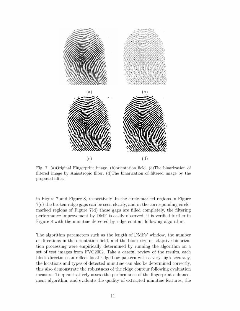
in Figure 7 and Figure 8, respectively. In the circle-marked regions in Figure7(c) the broken ridge gaps can be seen clearly, and in the corresponding circle-marked regions of Figure 7(d) those gaps are filled completely, the filteringperformance improvement by DMF is easily observed, it is verified further inFigure 8 with the minutiae detected by ridge contour following algorithm.
The algorithm parameters such as the length of DMFs’ window, the numberof directions in the orientation field, and the block size of adaptive binariza-tion processing were empirically determined by running the algorithm on aset of test images from FVC2002. Take a careful review of the results, eachblock direction can reflect local ridge flow pattern with a very high accuracy,the locations and types of detected minutiae can also be determined correctly,this also demonstrate the robustness of the ridge contour following evaluationmeasure. To quantitatively assess the performance of the fingerprint enhance-ment algorithm, and evaluate the quality of extracted minutiae features, the
11

(a) (b)
Fig. 8. (a) minutiae for the image filtered by Anisotropic filter. (b)minutiae for theimage filtered by the proposed filter.
following concepts are defined [4][12]:
Matched minutiae: A minutiae detected by the algorithm can match witha reasonable accuracy the ground truth minutiae.
Missed minutiae: Minutiae that were not found in the tolerence distance ofthe true minutiae
Spurious minutiae: Minutiae that were found in the region not containingtrue minutiae, i.e., the minutiae were created during enhancement process-ing, binarization, feature extractions.
Flipped minutiae: Detected minutiae type are different from the true minu-tiae type in the same image region.
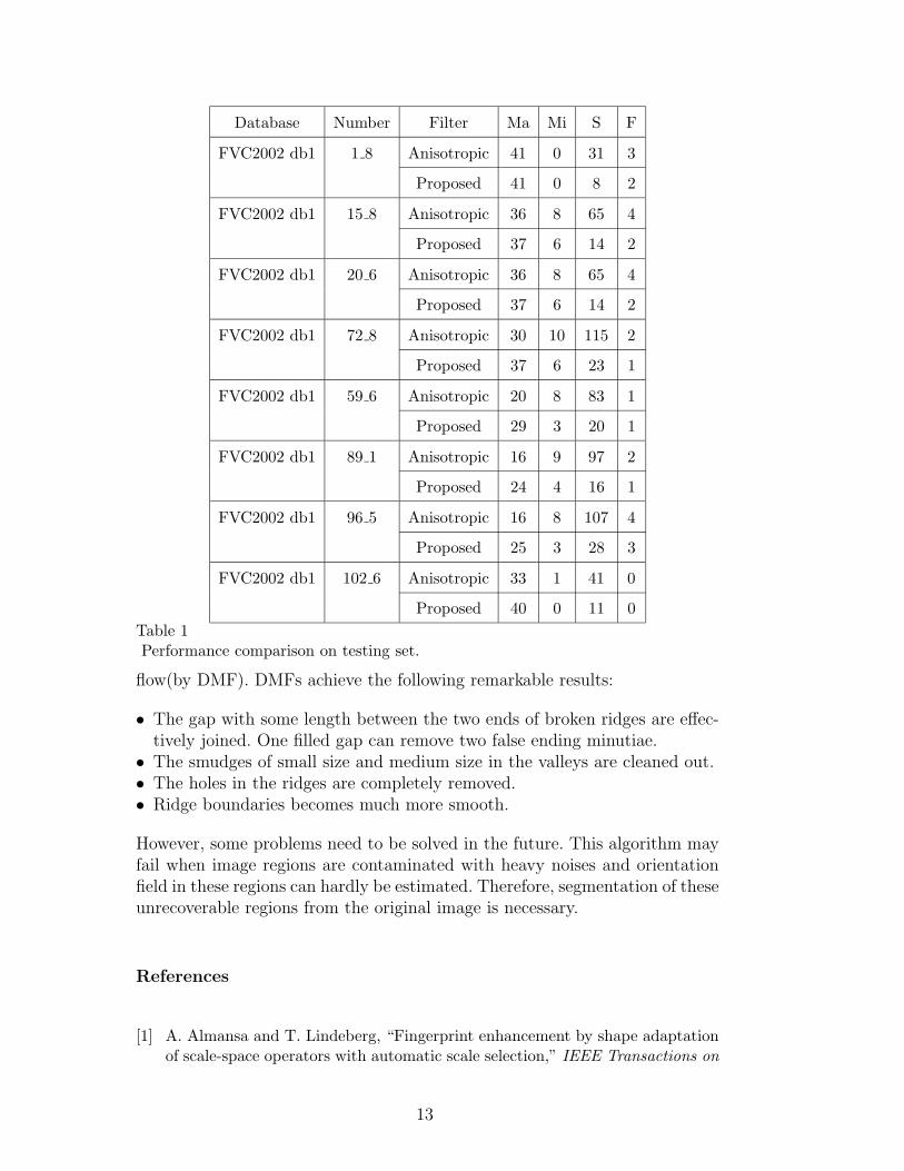
In Table 1, the comparison results for a representative subset of 8 fingerprintimages by anisotropic filter and proposed filter are shown in terms of matchedminutiae(Ma), missed minutiae(Mi), spurious minutiae(S) and flipped minu-tiae(F). Clearly, the proposed image enhancement algorithm has outperformedthe anisotropic in terms of feature extraction accuracy. It is necessary to pointout that most minutiae classified as spurious minutiae after filtering can beeliminated because they are generated by long gap of broken ridges. After en-hancement processing, the number of flipped or missed minutiae are relativelylow. Clearly, experimental results show our method to be superior to thosedescribed in the literature.
6 Conclusions and Future Work
This paper describes an intergration model for fingerprint image enhance-ment. Results shows this model can effectively reduce gaussian-distributednoises(by anisotropic filter) and impulse noises along the direction of ridge
12
Database Number Filter Ma Mi S F
FVC2002 db1 1 8 Anisotropic 41 0 31 3
Proposed 41 0 8 2
FVC2002 db1 15 8 Anisotropic 36 8 65 4
Proposed 37 6 14 2
FVC2002 db1 20 6 Anisotropic 36 8 65 4
Proposed 37 6 14 2
FVC2002 db1 72 8 Anisotropic 30 10 115 2
Proposed 37 6 23 1
FVC2002 db1 59 6 Anisotropic 20 8 83 1
Proposed 29 3 20 1
FVC2002 db1 89 1 Anisotropic 16 9 97 2
Proposed 24 4 16 1
FVC2002 db1 96 5 Anisotropic 16 8 107 4
Proposed 25 3 28 3
FVC2002 db1 102 6 Anisotropic 33 1 41 0
Proposed 40 0 11 0
Table 1Performance comparison on testing set.
flow(by DMF). DMFs achieve the following remarkable results:
• The gap with some length between the two ends of broken ridges are effec-tively joined. One filled gap can remove two false ending minutiae.
• The smudges of small size and medium size in the valleys are cleaned out.• The holes in the ridges are completely removed.• Ridge boundaries becomes much more smooth.
However, some problems need to be solved in the future. This algorithm mayfail when image regions are contaminated with heavy noises and orientationfield in these regions can hardly be estimated. Therefore, segmentation of theseunrecoverable regions from the original image is necessary.
References
[1] A. Almansa and T. Lindeberg, “Fingerprint enhancement by shape adaptationof scale-space operators with automatic scale selection,” IEEE Transactions on
13

Image Processing 9(12), pp. 2027–2042, 2000.
[2] L. O’Gorman and J. V. Nickerson, “An approach to fingerprint filter design.,”Pattern Recognition 22(1), pp. 29–38, 1989.
[3] V. Govindaraju, Z. Shi, and J. Schneider, “Feature extraction using chaincodedcontours of fingerprint images,” International Conference on Audio and Video
Based Biometric Person Authentication, Surrey, UK , 2003.
[4] S. Greenberg, M. Aladjem, and D. Kogan, “Fingerprint image enhancementusing filtering techniques,” Real–Time Imaging 8, pp. 227–236, 2002.
[5] R. C. Gonzalez and R. E. Woods, Digital Image Processing, Prentice Hall, UpperSaddle River, NJ, 2002.
[6] Y. He, J. Tian, X. Luo, and T. Zhang, “Image enhancement and minutiaematching in fingerprint verification,” Pattern Recognition Letters 24, pp. 1349–1360, 2003.
[7] L. Hong, Y. Wan, and A. K. Jain, “Fingerprint image enhancement: algorithmand performance evaluation.,” IEEE Transactions on Pattern Analysis and
Machine Intelligence 20(8), pp. 777–789, 1998.
[8] C. Hsieh and E. L. Y. Wang, “An effective algorithm for fingerprintimage enhancement based on wavelet transform,” Pattern Recognition 36(12),pp. 303–312, 2003.
[9] T. Ko, “Fingerprint enhancement by spectral analysis techniques,” 31st Applied
Imagery Pattern Recognition Workshop 31, pp. 16–18, 2002.
[10] D. Maltoni, D. Maio, A. K. Jain, and S. Prabhakar, Handbook of Fingerprint
Recognition, Springer, New York, NY, 2003.
[11] N. Otsu, “A threshold selection method from gray-level histogram,” IEEE
Transactions on Systems, Man and Cybernetics 9(1), pp. 62–66, 1979.
[12] N. K. Ratha, S. Y. Chen, and A. K. Jain, “Adaptive flow orientation-basedfeature extraction in fingerprint image,” Pattern Recognition 28(11), pp. 1657–1672, 1995.
[13] L. G. Shapiro and G. C. Stockman, Computer Vision, Prentice Hall, UpperSaddle River, NJ, 2000.
[14] B. G. Sherlock, D. M. Monro, and K. Millard, “Fingerprint enhancementby directional fourier filtering,” IEE Proc. Vis. Image Signal Process 141(2),pp. 87–94, 1994.
[15] M. Tico, V. Onnia, and P. Huosmanen, “Fingerprint image enhancement basedon second directional derivative of the digital image,” EURASIP Journal on
Applied Signal Processing 2002(10), pp. 1135–1144, 2002.
[16] A. J. Willis and L. Myers, “A cost-effective fingeprint recognition system foruse with low-quality prints and damaged fingertips,” Pattern Recognition 34(2),pp. 255–270, 2001.
14

[17] J. Yang, L. Liu, T. Jiang, and Y. Fan, “A modified gabor filter design method forfingerprint image enhancemen,” Pattern Recognition Letter 24, pp. 1805–1817,August 2003.
15