Embed Size (px)
Citation preview
FIREPLACE PRODUCTS INTERNATIONAL LTD. 6988 Venture St., Delta, BC Canada, V4G 1H4
WARNING:If the information in these instructions are not followed exactly,a fire or explosion may result causing property damage,personal injury or loss of life.
FOR YOUR SAFETYDo not store or use gasoline or other flammable vapors andliquids in the vicinity of this or any other appliance.
Installation and service must be performed by a qualifiedinstaller, service agency or the gas supplier.
FOR YOUR SAFETYWhat to do if you smell gas:!!!!! Do not try to light any appliance!!!!! Do not touch any electrical switch:
do not use any phone in yourbuilding.
!!!!! Immediately call your gas supplierfrom a neighbour's phone. Followthe gas supplier's instructions.
!!!!! If you cannot reach your gassupplier, call the fire department.
908-804
MODELS: E63-NG1 Natural Gas E63-LP1 Propane
Tested by: Installer: Please complete the details on the back coverand leave this manual with the homeowner.
Homeowner: Please keep these instructions for future reference.
05/29/03
EMERALD Vented Gas Heater Owners &Installation Manual
WATERFORDFine Porcelain Enamel, Cast Iron Stoves from Ireland

2 Waterford E63-1 EMERALD Freestanding Gas Stove
To the New Owner:
Congratulations! You are the owner of a state-of-the-art EMERALD Gas Stove by Waterford Irish
Stoves. The Waterford Gas Series of hand crafted appliances has been designed to provide you with
all the warmth and charm of a woodstove, at the flick of a switch. The models E63-NG1 and E63-LP1
of this series has been approved by Warnock Hersey for both safety and efficiency. As it also bears
our own mark, it promises to provide you with economy, comfort and security for many trouble free years
to follow. Please take a moment now to acquaint yourself with these instructions and the many features
of your Waterford Gas Stove.
Minor imperfections such as blisters, seeds or thin flaws
visible in this product are not defects. These are inherent in
the hand-crafted enamel process and cannot be avoided, and
they substantiate that this is genuine porcelain enamel.

Waterford E63-1 EMERALD Freestanding Gas Stove 3
TABLE OF CONTENTS
Page Page
Operating Instructions
Operating Instructions ........................................................ 15
Lighting Instructions ........................................................... 15
Shutdown Instructions ....................................................... 15
First Fire .............................................................................. 15
Convection Fan Operation ................................................. 15
Flame Height Adjustment .................................................. 15
Copy of Lighting Plate Instructions .................................... 16
Normal Operating Sounds of Gas Appliances .................. 16
Maintenance
Maintenance Instructions ................................................... 17
Pilot Adjustment ................................................................. 17
Log Replacement ............................................................... 17
Glass Replacement ........................................................... 17
Gasket Replacement ......................................................... 18
Fan Maintenance ................................................................ 18
Valve Maintenance ............................................................. 18
Parts List ............................................................................ 20
Warranty
Warranty .............................................................................. 23
Safety Label
Safety Label .......................................................................... 4
Installation
General Installation Information .......................................... 6
Installation Checklist ............................................................ 6
Minimum Clearances to Combustibles .............................. 7
Optional Fan Installation ...................................................... 7
Draft Hood ............................................................................ 8
High Elevation ...................................................................... 8
Venting .................................................................................. 8
- Venting Requirements ..................................................... 8
- Vent Terminations ............................................................ 8
- Installation into Existing Woodstove Flue System ........... 8
Gas Connection ................................................................... 9
System Data ......................................................................... 9
Aeration Adjustment ............................................................. 9
Gas Pressure Test ............................................................... 9
Conversion to Propane ...................................................... 10
Reduction to Lower Btu Rating .......................................... 11
Log Installation ................................................................... 12
Optional Door Grill .............................................................. 13
Test for Flue Spillage ......................................................... 13
Optional Wall Thermostat .................................................. 13
Optional Remote Control Installation ................................ 13
Final Check ......................................................................... 14
Wiring Diagram .................................................................. 14
4 Waterford E63-1 EMERALD Freestanding Gas Stove
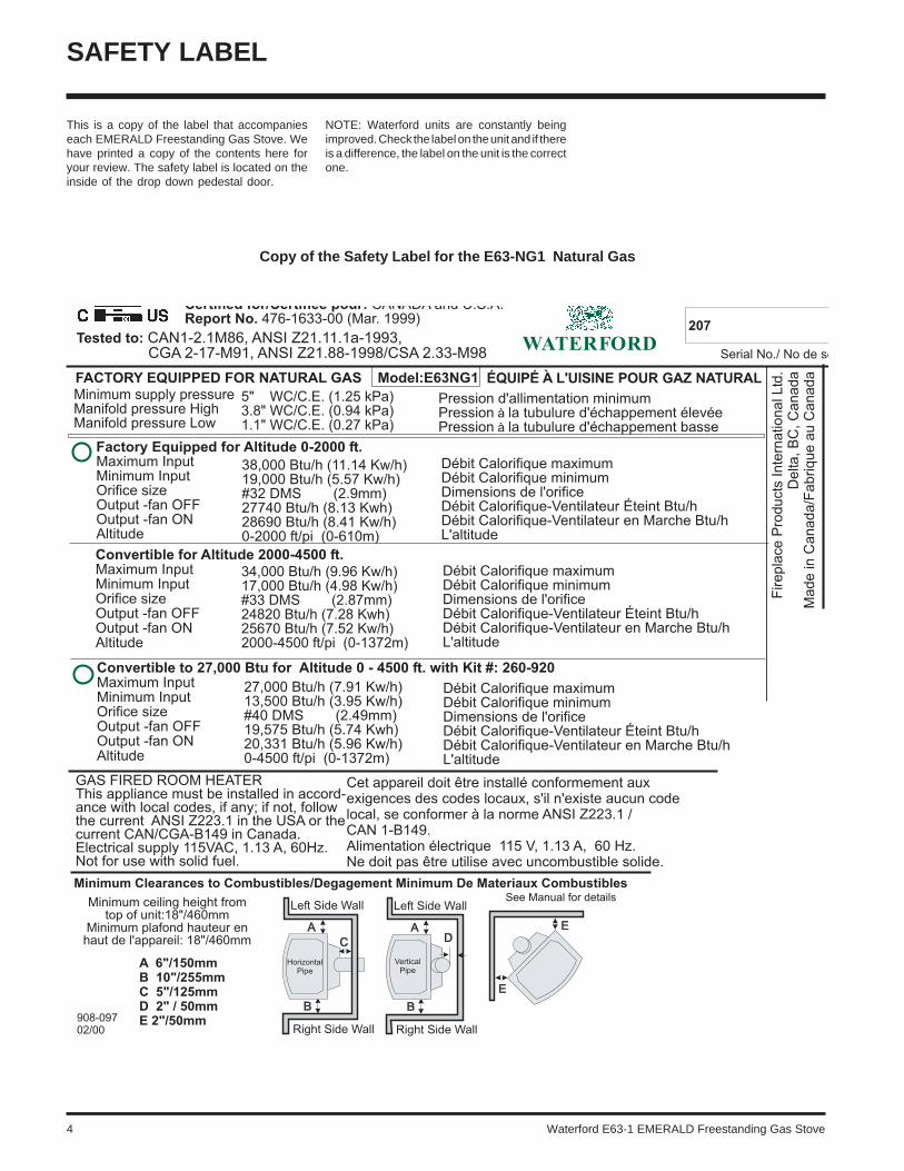
This is a copy of the label that accompanieseach EMERALD Freestanding Gas Stove. Wehave printed a copy of the contents here foryour review. The safety label is located on theinside of the drop down pedestal door.
NOTE: Waterford units are constantly beingimproved. Check the label on the unit and if thereis a difference, the label on the unit is the correctone.
SAFETY LABEL
Copy of the Safety Label for the E63-NG1 Natural Gas

Waterford E63-1 EMERALD Freestanding Gas Stove 5
Copy of the Safety Label for the E63-LP1 Propane
SAFETY LABEL
For the State of Massachusetts, installationand repair must be done by a plumber orgasfitter licensed in the Commonwealth ofMassachusetts.
For the State of Massachusetts, flexibleconnectors shall not exceed 36 inches inlength.
For the State of Massachusetts, the appli-ances individual manual shut-off must be at-handle type valve.

6 Waterford E63-1 EMERALD Freestanding Gas Stove
12) Under no circumstances should this appli-ance be modified. Parts that have to beremoved for servicing should be replacedprior to operating this appliance.
13) Installation and any repairs to this applianceshould be done by a qualified service per-son. A professional service person shouldbe called to inspect this appliance annually.Make it a practice to have all of your gasappliances checked annually.
14) Do not strike the glass door.
15) Under no circumstances should any solidfuels (wood, paper, cardboard, coal, etc.)be used in this appliance.
16) The appliance area must be kept clear andfree of combustible materials, (gases andother flammable vapours and liquids).
17) This unit can be installed on a solid combus-tible surface like a wood floor as well as oncarpeting.
18) Do not connect this gas appliance to chim-ney flue serving a separate sold-fuel burn-ing appliance.
19) WARNING: Operation of this appliance whennot connected to a properly installed andmaintained venting system or tampering withthe blocked vent shutoff system can resultin carbon monoxide (CO) poisoning andpossible death.
20) This appliance needs fresh air for safeoperation and must be installed so there areprovisions for adequate combustion andventilation air.
INSTALLATIONCHECKLIST
1) Check Clearances to Combustibles, page 7.
2) Install Optional Fan, page 7.
3) Install venting, page 8.
4) Make gas connections, page 9. Test thepilot. Must be as per diagram, page 17. Ifconverting to Propane (see page 10, or ifconverting to lower Btu Rating (see page11).
5) Test Gas Pressure, page 9.
6) Install log set where indicated on page 12.
7) Test for flue spillage (draft test), page 13.
INSTALLATION
BEFORE YOU START
Safe installation and operation of this appliancerequires common sense, however, we arerequired by the Canadian Safety Standardsand ANSI Standards to make you aware of thefollowing:
IMPORTANT:SAVE THESE
INSTRUCTIONS
The EMERALD Freestanding Gas Stove mustbe installed in accordance with these instruc-tions. Carefully read all the instructions in thismanual first. Consult the "authority having juris-diction" to determine the need for a permit priorto starting the installation.
GENERAL SAFETYINFORMATION
1) The appliance installation must conformwith local codes or, in the absence of localcodes, with the current Canadian or Nation-al Gas Codes, CAN1-B149 or ANSI-223.1Installation Codes.
2) The appliance when installed, must be elec-trically grounded in accordance with localcodes, or in the absence of local codes withthe current National Electrical Code, ANSI/NFPA 70 or CSA C22.1 Canadian ElectricalCode.
3) This appliance is Listed for bedroom instal-lations when used with a Listed MillivoltThermostat. Some areas may have furtherrequirements, check local codes beforeinstallation.
4) This appliance is Listed for Alcove installa-tions, maintain minimum Alcove clearancesas follows, minimum ceiling height of 47",minimum width of 41" and a maximum depthof 24".
5) This unit is not approved for installation intoa mobile home.
6) See general construction and assemblyinstructions.
7) This appliance must be connected to a ventand terminate to the outside of the buildingenvelope. Never vent to another room orinside a building.
8) Inspect the venting system annually forblockage and any signs of deterioration.
9) Any safety glass removed for servicingmust be replaced prior to operating theappliance.
10) To prevent injury, do not allow anyone whois unfamiliar with the operation to use thefireplace.
11) Wear gloves and safety glasses for pro-tection while doing required maintenance.
INSTALLATION AND REPAIRSHOULD BE DONE BY A QUALI-FIED SERVICE PERSON. THE AP-PLIANCE SHOULD BE INSPECTEDBEFORE USE AND AT LEAST AN-NUALLY BY A PROFESSIONALSERVICE PERSON. MORE FRE-QUENT CLEANING MAY BE RE-QUIRED DUE TO EXCESSIVE LINTFROM CARPETING, BEDDING MA-TERIAL, ETC. IT IS IMPERATIVETHAT CONTROL COMPART-MENTS, BURNERS AND CIRCULAT-ING AIR PASSAGEWAYS OF THEAPPLIANCE BE KEPT CLEAN.
DUE TO HIGH TEMPERATURES,THE APPLIANCE SHOULD BE LO-CATED OUT OF TRAFFIC ANDAWAY FROM FURNITURE ANDDRAPERIES.
WARNING: FAILURE TO INSTALLTHIS APPLIANCE CORRECTLYMAY CAUSE A SERIOUS HOUSEFIRE AND WILL VOID YOUR WAR-RANTY.
CHILDREN AND ADULTS SHOULDBE ALERTED TO THE HAZARDSOF HIGH SURFACE TEMPERA-TURES, ESPECIALLY THE FIRE-PLACE GLASS, AND SHOULDSTAY AWAY TO AVOID BURNS ORCLOTHING IGNITION.
YOUNG CHILDREN SHOULD BECAREFULLY SUPERVISED WHENTHEY ARE IN THE SAME ROOM ASTHE APPLIANCE.
CLOTHING OR OTHER FLAMMA-BLE MATERIAL SHOULD NOT BEPLACED ON OR NEAR THE APPLI-ANCE.
Emissions from burning wood or gas couldcontain chemicals known to the State ofCalifornia to cause cancer, birth defects orother reproductive harm.
Waterford E63-1 EMERALD Freestanding Gas Stove 7
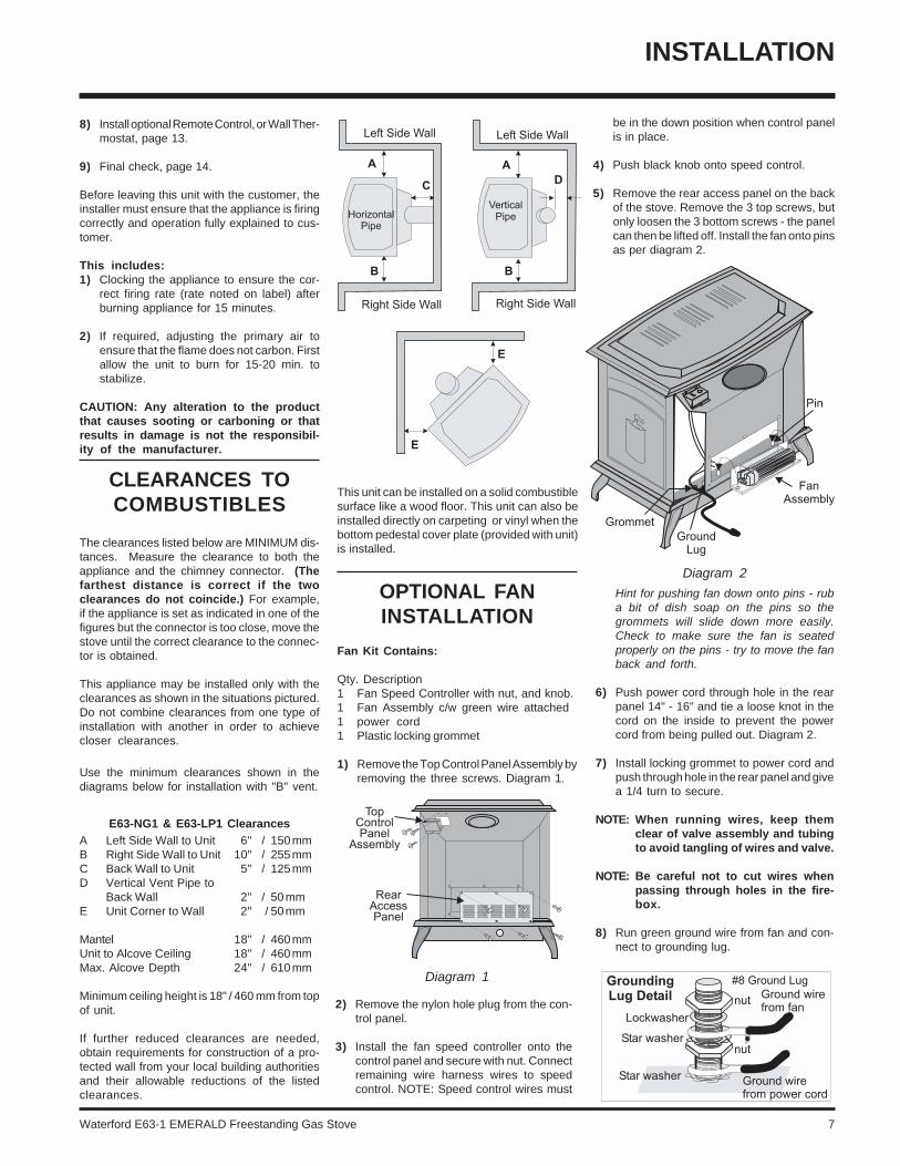
OPTIONAL FANINSTALLATION
Fan Kit Contains:
Qty. Description1 Fan Speed Controller with nut, and knob.1 Fan Assembly c/w green wire attached1 power cord1 Plastic locking grommet
1) Remove the Top Control Panel Assembly byremoving the three screws. Diagram 1.
be in the down position when control panelis in place.
4) Push black knob onto speed control.
5) Remove the rear access panel on the backof the stove. Remove the 3 top screws, butonly loosen the 3 bottom screws - the panelcan then be lifted off. Install the fan onto pinsas per diagram 2.
Diagram 1
Diagram 2
Hint for pushing fan down onto pins - ruba bit of dish soap on the pins so thegrommets will slide down more easily.Check to make sure the fan is seatedproperly on the pins - try to move the fanback and forth.
6) Push power cord through hole in the rearpanel 14" - 16" and tie a loose knot in thecord on the inside to prevent the powercord from being pulled out. Diagram 2.
7) Install locking grommet to power cord andpush through hole in the rear panel and givea 1/4 turn to secure.
NOTE: When running wires, keep themclear of valve assembly and tubingto avoid tangling of wires and valve.
NOTE: Be careful not to cut wires whenpassing through holes in the fire-box.
8) Run green ground wire from fan and con-nect to grounding lug.
INSTALLATION
8) Install optional Remote Control, or Wall Ther-mostat, page 13.
9) Final check, page 14.
Before leaving this unit with the customer, theinstaller must ensure that the appliance is firingcorrectly and operation fully explained to cus-tomer.
This includes:1) Clocking the appliance to ensure the cor-
rect firing rate (rate noted on label) afterburning appliance for 15 minutes.
2) If required, adjusting the primary air toensure that the flame does not carbon. Firstallow the unit to burn for 15-20 min. tostabilize.
CAUTION: Any alteration to the productthat causes sooting or carboning or thatresults in damage is not the responsibil-ity of the manufacturer.
CLEARANCES TOCOMBUSTIBLES
The clearances listed below are MINIMUM dis-tances. Measure the clearance to both theappliance and the chimney connector. (Thefarthest distance is correct if the twoclearances do not coincide.) For example,if the appliance is set as indicated in one of thefigures but the connector is too close, move thestove until the correct clearance to the connec-tor is obtained.
This appliance may be installed only with theclearances as shown in the situations pictured.Do not combine clearances from one type ofinstallation with another in order to achievecloser clearances.
Use the minimum clearances shown in thediagrams below for installation with "B" vent.
E63-NG1 & E63-LP1 ClearancesA Left Side Wall to Unit 6" / 150 mmB Right Side Wall to Unit 10" / 255 mmC Back Wall to Unit 5" / 125 mmD Vertical Vent Pipe to
Back Wall 2" / 50 mmE Unit Corner to Wall 2" / 50 mm
Mantel 18" / 460 mmUnit to Alcove Ceiling 18" / 460 mmMax. Alcove Depth 24" / 610 mm
Minimum ceiling height is 18" / 460 mm from topof unit.
If further reduced clearances are needed,obtain requirements for construction of a pro-tected wall from your local building authoritiesand their allowable reductions of the listedclearances.
This unit can be installed on a solid combustiblesurface like a wood floor. This unit can also beinstalled directly on carpeting or vinyl when thebottom pedestal cover plate (provided with unit)is installed.
2) Remove the nylon hole plug from the con-trol panel.
3) Install the fan speed controller onto thecontrol panel and secure with nut. Connectremaining wire harness wires to speedcontrol. NOTE: Speed control wires must

8 Waterford E63-1 EMERALD Freestanding Gas Stove
Vent Terminations
Installation into ExistingWoodstove Flue System
1) Clean existing Chimney system.
2) Run an approved 4" flex liner or "B" ventinto existing chimney.
DRAFT HOOD
This heater has a draft hood built in. It must notbe altered, obstructed, or blocked in any way,and the unit must be installed so that the drafthood is in the same atmospheric pressure zoneas the combustion air inlet to the burner. Thisheater must be properly connected to a ventingsystem. This heater is equipped with a ventsafety shutoff system.
WARNING: Operation of this heaterwhen not connected to a properlyinstalled and maintained ventingsystem or tampering with the ventsafety shutoff system can result incarbon monoxide (CO) poisoningand possible death.
HIGH ELEVATION
The E63-1 (with 38,000 Btu) is approved inCanada for altitude 2000 ft. to 4500 ft. (CAN/CGA-2.17-M91) with the orifice kit (Part # 591-975). For Natural Gas installations above 4500ft. follow current CAN/CGA-B149.1.
In U.S.A., for installations above 2000 ft. referto current ANSI Z223.1 Sc8-8.1.2a appendix F,for resizing orifice.
VENTING
This heater is a vented appliance and must beconnected to a chimney/flue in accordancewith the installation codes.
Note: The rear pedestal cover plate isonly required when outside air isbeing used. If using room air forcombustion, remove this platefrom the back of the pedestal.
For your safety this heater is equipped with avent safety switch designed to sense incorrectventing and react by shutting down the gassupply. This thermally actuated switch is locat-ed within the draft hood and will detect eithera blocked chimney or backdraft condition wherethe chimney flow has reversed. If this switchshuts the unit down, it indicates a draftingproblem that must be identified and rectifiedwithout delay - the thermally activated switchmust never be bypassed or disconnected asa hazardous or deadly condition can result.
Venting Requirements
A four inch diameter vent is required. B-Vent,Class A or Masonry with an approved liner areall acceptable. For cosmetic or aesthetic pur-poses 6" outer vent can be used as long as anapproved inner vent is installed. Fasten but do
INSTALLATION
9) Connect green power cord ground wire togrounding lug.
10) Run neutral black wire from power cordand connect to fan motor.
11) Run live black wire from power cord andconnect to speed control wire.
12) Connect the white wire of the wire har-ness to the fan terminal.
NOTE: Pull excess wire next to fan toavoid excessive heat from the fire-box.
13) Ensure all wires are pulled away fromfirebox to avoid excessive heat and se-cure with stick-on wire clip.
14) Re-attach control panel with 3 screws,reversing step 1. Re-attach rear accesspanel with 6 screws, reversing step 5.
NOTE: When power cord is plugged in,speed control is in the ON posi-tion and stove is burning, allow 10- 15 minutes for the thermodisc(temperature switch) to activateand turn on the Fan automatically.
WARNING:Electrical Grounding InstructionsThis appliance is equipped with athree pronged (grounding) plug foryour protection against shock haz-ard and should be plugged directlyinto a properly grounded three-prong receptacle. Do not cut orremove the grounding prong fromthis plug.
not penetrate the inner sleeve of the B-Ventwhen tightening the screw.
Follow all venting manufacturer’s requirementsand local building codes. In cold climates, werecommend the use of insulated B-vent, chase,and liners. For altitudes above 2000 ft. werecommend that a minimum flue height of 12 ft.is used.
Note: See the chimneysystems manufac-turer for detailedinstallationinstructions.

Waterford E63-1 EMERALD Freestanding Gas Stove 9
INSTALLATION
System Data - E63-1(with 38,000 Btu)
For 0 to 2000 feet altitude
Burner Inlet Orifice Sizes: Natural Gas Propane
Burner #32 #50*Above 2000 ft. see National Fuel CodeOrifice Chart.
Max. Input RatingNatural Gas 38,000 Btu/hPropane 38,000 Btu/h
Min. Input RatingNatural Gas 19,000 Btu/hPropane 19,000 Btu/h
Output Capacity with blower OffNatural Gas 27,740 Btu/hPropane 28,500 Btu/h
Output Capacity with blower OnNatural Gas 28,690 Btu/hPropane 29,374 Btu/h
Supply PressureNatural Gas min. 5.0" w.c.Propane min. 12.0" w.c.
Manifold PressureNatural Gas 3.8" +/- 0.2" w.c.Propane 11" +/- 0.2" w.c.
System Data -HIGH ELEVATION: E63-NG1
For 2,000 - 4,500 feet altitude
Burner Inlet Orifice Sizes: Natural Gas
Burner #33
Max. Input RatingNatural Gas 34,000 Btu/h
Min. Input RatingNatural Gas 17,000 Btu/h
Output Capacity with blower OffNatural Gas 24,820 Btu/h
Max. Output Capacity with blower OnNatural Gas 25,670 Btu/h
System Data -E63-1 converted to
27,000 Btu (NG) or 29,000 (LP)
For 0 to 4500 feet altitude
Burner Inlet Orifice Sizes: Natural Gas Propane
Burner #40 #52
Max. Input RatingNatural Gas 27,000 Btu/hPropane 29,000 Btu/h
Min. Input RatingNatural Gas 13,500 Btu/hPropane 14,500 Btu/h
Output Capacity with blower OffNatural Gas 20,331 Btu/hPropane 22,330 Btu/h
Output Capacity with blower OnNatural Gas 19,575 Btu/hPropane 21,518 Btu/h
Supply PressureNatural Gas min. 5.0" w.c.Propane min. 12.0" w.c.
Manifold PressureNatural Gas 3.8" +/- 0.2" w.c.Propane 11" +/- 0.2" w.c.
AERATIONADJUSTMENT
The burner aeration is factory set but may needadjusting due to either the local gas supply, airsupply or altitude.
The aeration adjustment gears are located onthe right side of the burner box and can beaccessed from the side.
To adjust the aeration: use the allen key to turnthe turning gear which will adjust the air shut-ter. Open the air shutter for a blue flame or closeit for a yellower flame. This adjustment isperformed by a qualified installer. The factorysetting should be sufficient for most installa-tions.
with 38,000 Btu with 27,000 (NG) / 29,000 LP
Natural Gas Natural Gas
3/8"(9.5mm) 3/16"(4.75mm)
Propane Propane
wide open 1/4" (6.35mm)
Clockwise to open,counter-clockwise to close.
Caution: Carbon will be produced if theair shutter is closed too much.
Note: Any damage due to carboningresulting from improperly settingthe aeration controls is NOT cov-ered under warranty.
Note: Aeration Adjustment should onlybe performed by an authorizedRegency Installer at the time ofinstallation or service.
GAS PIPE PRESSURETESTING
The appliance must be isolated from the gassupply piping system by closing its individualmanual shut-off valve during any pressuretesting of the gas supply piping system at testpressures equal to or less than 1/2 psig. (3.45kPa). Disconnect piping from valve at pres-sures over 1/2 psig (14" w.c.).
The manifold pressure is controlled by a regu-lator built into the gas control, and should bechecked at the pressure test point.
Note: To properly check gas pressure,both inlet and manifold pressuresshould be checked using the valvepressure ports on the valve.
1) Make sure the valve is in the "OFF" position.
GAS CONNECTION
The gas line can be rigid pipe, or to makeinstallation easier, use a listed flexible connec-tor if allowed by local codes. Copper may alsobe used if approved by local codes.
The gas connection at the valve is 3/8" NPT. Forminimum and maximum supply pressure see theSystem Data Table.

10 Waterford E63-1 EMERALD Freestanding Gas Stove
INSTALLATION
2) Loosen the "IN" (# 7) and/or "OUT" (# 6)pressure tap(s), turning counterclockwisewith a 1/8" wide flat screwdriver.
3) Attach manometer to "IN" and/or "OUT"pressure tap(s) using a 5/16" ID hose.
4) Light the pilot and turn the valve to "ON"position.
5) The pressure check should be carried outwith the unit burning and the setting shouldbe within the limits specified on the safetylabel.
6) When finished reading manometer, turn offthe gas valve, disconnect the hose andtighten the screw (clockwise) with a 1/8"flat screwdriver. Screw should be snug,but do not over tighten.
S.I.T. Valve Description
1) Gas cock knob
2) Manual high/low adjustment
3) Pilot Adjustment
4) Thermocouple Connection
5) Main Operator
6) Outlet Pressure Tap
7) Inlet Pressure Tap
8) Pilot Outlet
9) Main Gas Outlet
10) Flange Securing Screw Holes
11) Alternative TC Connection Point
12) Thermoelectric Unit
13) Additional Valve Mounting Hole
4) Carefully remove the logs, embers androckwool.
5) Remove burner. See diagram below.
Pilot assembly is now accessiblefor steps 6) to 11).
Note: Use a magnetic type screwdriver ifpossible.
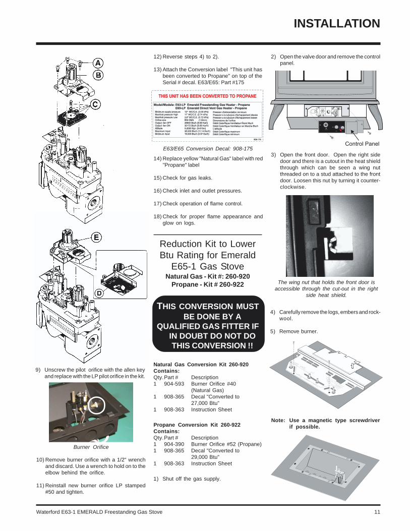
6) Remove and discard the 3 pressure regu-lator mounting screws (A), pressure reg-ulator tower (B) and diaphragm (C).
7) Insure that the rubber gasket (D) is properlypositioned and install the new HI/LO pres-sure regulator assembly to the valve usingthe new screws (E) supplied with the kit.Tighten screws securely.
8) Pull off the pilot cap to expose the pilotorifice.
THIS CONVERSION MUSTBE DONE BY A
QUALIFIED GASFITTER IF IN DOUBT DO
NOT DO THISCONVERSION !!
3) Open the front door. Open the right sidedoor and there is a cutout in the heat shieldthrough which can be seen a wing nutthreaded on to a stud attached to the frontdoor. Loosen this nut by turning it counter-clockwise.
Conversion Kit Contains:
Qty. Part # Description1 910-018 SIT Conversion Kit-50%
Turndown LP1 910-037 LP Injector (Pilot Orifice)1 904-641 Burner Orifice #501 908-175 E63/E65 Decal "Converted to
Propane"1 908-528 Red "PROPANE" label1 908-780 Instruction Sheet
1) Shut off the gas supply.
2) Open the valve door and remove the controlpanel.
CONVERSION KITFROM NATURAL GAS
TO PROPANEModel #261-969
for Emerald Gas Stoves and GasInserts using SIT 820 NOVA Gas
Valve
Waterford E63-1 EMERALD Freestanding Gas Stove 11
Reduction Kit to LowerBtu Rating for Emerald
E65-1 Gas StoveNatural Gas - Kit #: 260-920
Propane - Kit # 260-922
THIS CONVERSION MUSTBE DONE BY A
QUALIFIED GAS FITTER IFIN DOUBT DO NOT DOTHIS CONVERSION !!
4) Carefully remove the logs, embers and rock-wool.
5) Remove burner.
Natural Gas Conversion Kit 260-920Contains:Qty.Part # Description1 904-593 Burner Orifice #40
(Natural Gas)1 908-365 Decal "Converted to
27,000 Btu"1 908-363 Instruction Sheet
Propane Conversion Kit 260-922Contains:Qty.Part # Description1 904-390 Burner Orifice #52 (Propane)1 908-365 Decal "Converted to
29,000 Btu"1 908-363 Instruction Sheet
1) Shut off the gas supply.
The wing nut that holds the front door isaccessible through the cut-out in the right
side heat shield.
Note: Use a magnetic type screwdriverif possible.
INSTALLATION
E63/E65 Conversion Decal: 908-175
Burner Orifice
9) Unscrew the pilot orifice with the allen keyand replace with the LP pilot orifice in the kit.
10) Remove burner orifice with a 1/2" wrenchand discard. Use a wrench to hold on to theelbow behind the orifice.
11) Reinstall new burner orifice LP stamped#50 and tighten.
12) Reverse steps 4) to 2).
13) Attach the Conversion label "This unit hasbeen converted to Propane" on top of theSerial # decal. E63/E65: Part #175
14) Replace yellow "Natural Gas" label with red"Propane" label
15) Check for gas leaks.
16) Check inlet and outlet pressures.
17) Check operation of flame control.
18) Check for proper flame appearance andglow on logs.
2) Open the valve door and remove the controlpanel.
3) Open the front door. Open the right sidedoor and there is a cutout in the heat shieldthrough which can be seen a wing nutthreaded on to a stud attached to the frontdoor. Loosen this nut by turning it counter-clockwise.

12 Waterford E63-1 EMERALD Freestanding Gas Stove
OPTIONAL DOORGRILL INSTALLATION
Door Grill Kit Contains:
Qty. Description1 Front Door Grill4 Screws4 Grill Clips
1) Open the front door. Open the right sidedoor and there is a cutout in the heat shieldthrough which can be seen a wing nutthreaded on to a stud attached to the frontdoor. Loosen this nut by turning it counter-clockwise.
5) Distribute the embers along the front burnerbut do not cover the burner ports andaround the logs. Place the embers on thefloor of the firebox. Place the lava on theburner tray in front of the left and right frontlogs. See Diagram 4.
Diagram 4
Diagram 3
Diagram 1Note: Do not force logs down.
Diagram 2
LOG INSTALLATION
WARNING: Dangerous operating condi-tions may occur if these logs are notpositioned in their approved locations.Read the instructions below carefully andrefer to the diagrams. If logs are brokendo not use the unit until they are replaced.Broken logs can interfere with the pilotand burner operation.
a) Front Right Log - Part # 902-020b) Front Left Log - Part # 902-021c) Rear log - Part # 902-022d) Embers - Part # 902-151 (1 bag)e ) Lava - Part # 902-154 (1 bag)
(Part # 560-935 for the set of three logs)
1) Remove the logs from the box and carefullyunwrap them. The logs are fragile, handlewith care - DO NOT FORCE into position.
2) Place the rear log, carefully sliding it downonto the pins, with the flat side of the logfacing the back of the unit. See diagram 1.
3) Place the left front log, carefully sliding itdown onto the left pins of the front burner.See diagram 2.
4) Place the right front log, carefully sliding itdown onto the right pins of the front burner.See diagram 3.
Burner Orifice
INSTALLATION
6) Remove burner orifice with a 1/2" wrenchand discard.
7) Reinstall new burner orifice (NG stamped#40 or LP stamped #52) and tighten.
8) Reverse steps 5) to 2).
9) Attach the label "This unit has been con-verted to..." on top of the Serial # decal overthe higher Btu information.
10) Check for gas leaks.
11) Check inlet and outlet pressures.
12) Check operation of flame control. Check forproper flame appearance and glow on logs.
2) Remove the glass panel by loosening the 6screws securing the glass brackets. Sup-port the glass to prevent it from droppingout and breaking.
Waterford E63-1 EMERALD Freestanding Gas Stove 13
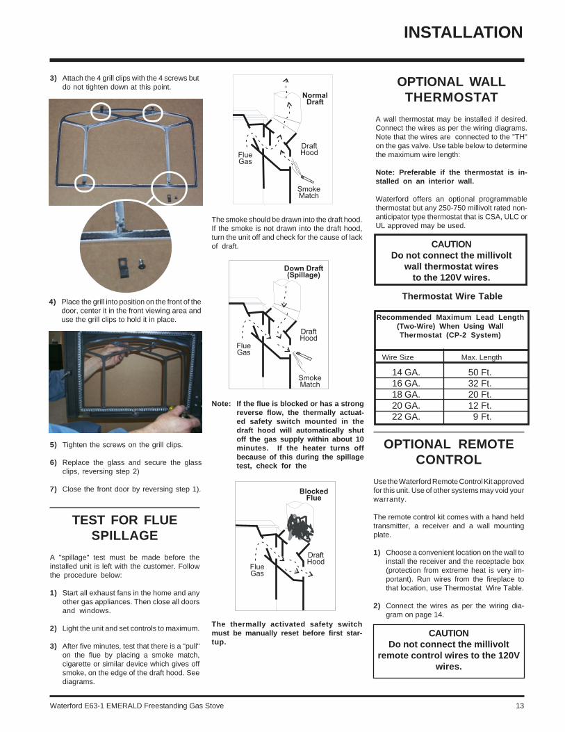
OPTIONAL REMOTECONTROL
Use the Waterford Remote Control Kit approvedfor this unit. Use of other systems may void yourwarranty.
The remote control kit comes with a hand heldtransmitter, a receiver and a wall mountingplate.
1) Choose a convenient location on the wall toinstall the receiver and the receptacle box(protection from extreme heat is very im-portant). Run wires from the fireplace tothat location, use Thermostat Wire Table.
2) Connect the wires as per the wiring dia-gram on page 14.
CAUTIONDo not connect the millivolt
remote control wires to the 120Vwires.
OPTIONAL WALLTHERMOSTAT
A wall thermostat may be installed if desired.Connect the wires as per the wiring diagrams.Note that the wires are connected to the "TH"on the gas valve. Use table below to determinethe maximum wire length:
Note: Preferable if the thermostat is in-stalled on an interior wall.
Waterford offers an optional programmablethermostat but any 250-750 millivolt rated non-anticipator type thermostat that is CSA, ULC orUL approved may be used.
CAUTIONDo not connect the millivolt
wall thermostat wiresto the 120V wires.
INSTALLATION
3) Attach the 4 grill clips with the 4 screws butdo not tighten down at this point.
14 GA.16 GA.18 GA.20 GA.22 GA.
50 Ft.32 Ft.20 Ft.12 Ft.9 Ft.
Recommended Maximum Lead Length(Two-Wire) When Using WallThermostat (CP-2 System)
Wire Size Max. Length
Thermostat Wire Table4) Place the grill into position on the front of the
door, center it in the front viewing area anduse the grill clips to hold it in place.
5) Tighten the screws on the grill clips.
6) Replace the glass and secure the glassclips, reversing step 2)
7) Close the front door by reversing step 1).
The thermally activated safety switchmust be manually reset before first star-tup.
TEST FOR FLUESPILLAGE
A "spillage" test must be made before theinstalled unit is left with the customer. Followthe procedure below:
1) Start all exhaust fans in the home and anyother gas appliances. Then close all doorsand windows.
2) Light the unit and set controls to maximum.
3) After five minutes, test that there is a "pull"on the flue by placing a smoke match,cigarette or similar device which gives offsmoke, on the edge of the draft hood. Seediagrams.
The smoke should be drawn into the draft hood.If the smoke is not drawn into the draft hood,turn the unit off and check for the cause of lackof draft.
Note: If the flue is blocked or has a strongreverse flow, the thermally actuat-ed safety switch mounted in thedraft hood will automatically shutoff the gas supply within about 10minutes. If the heater turns offbecause of this during the spillagetest, check for the
14 Waterford E63-1 EMERALD Freestanding Gas Stove
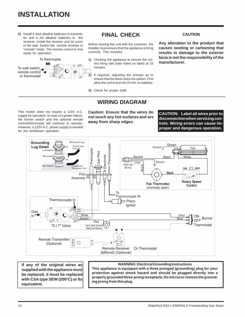
WIRING DIAGRAM
INSTALLATION
FINAL CHECK
Before leaving this unit with the customer, theinstaller must ensure that the appliance is firingcorrectly. This includes:
1) Clocking the appliance to ensure the cor-rect firing rate (rate noted on label) at 15minutes.
2) If required, adjusting the primary air toensure that the flame does not carbon. Firstallow the unit to burn for 15 min. to stabilize.
3) Check for proper draft.
3) Install 3 AAA alkaline batteries in transmit-ter and 4 AA alkaline batteries in thereceiver. Install the receiver and its coverin the wall. Switch the remote receiver to"remote" mode. The remote control is nowready for operation.
CAUTION
Any alteration to the product thatcauses sooting or carboning thatresults in damage to the exteriorfacia is not the responsibility of themanufacturer.
This heater does not require a 120V A.C.supply for operation. In case of a power failure,the burner switch and the optional remotecontrol/thermostat will continue to operate.However, a 120V A.C. power supply is neededfor the fan/blower operation.
Caution: Ensure that the wires donot touch any hot surfaces and areaway from sharp edges.
If any of the original wires assupplied with the appliance mustbe replaced, it must be replacedwith CSA type SEW (200oC) or itsequivalent.
CAUTION: Label all wires prior todisconnection when servicing con-trols. Wiring errors can cause im-proper and dangerous operation.
WARNING: Electrical Grounding InstructionsThis appliance is equipped with a three pronged (grounding) plug for yourprotection against shock hazard and should be plugged directly into aproperly grounded three-prong receptacle. Do not cut or remove the ground-ing prong from this plug.
Waterford E63-1 EMERALD Freestanding Gas Stove 15
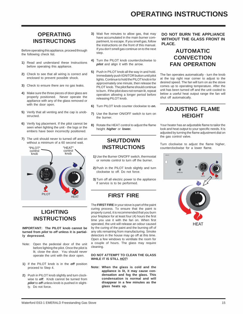
OPERATING INSTRUCTIONS
3) Wait five minutes to allow gas, that mayhave accumulated in the main burner com-partment, to escape. If you smell gas, followthe instructions on the front of this manual.If you don't smell gas continue on to the nextstep.
4) Turn the PILOT knob counterclockwise topilot and align it with the arrow.
5) Push in PILOT knob all the way in and hold.Immediately push IGNITOR button until pilotlights. Continue to hold the PILOT knob in forapproximately one minute, then release thePILOT knob. The pilot flame should continueto burn. If the pilot does not remain lit, repeatoperation allowing a longer period beforereleasing PILOT knob.
6) Turn PILOT knob counter clockwise to on.
7) Use the Burner ON/OFF switch to turn onthe burner.
8) Rotate the HEAT control to adjust the flameheight higher or lower.
SHUTDOWNINSTRUCTIONS
1) Use the Burner ON/OFF switch, thermostator remote control to turn off the burner.
2) Push in the PILOT knob slightly and turnclockwise to off. Do not force.
3) Turn off all electric power to the applianceif service is to be performed.
FIRST FIRE
The FIRST FIRE in your stove is part of the paintcuring process. To ensure that the paint isproperly cured, it is recommended that you burnyour fireplace for at least four (4) hours the firsttime you use it with the fan on. When firstoperated, the unit will release an odour causedby the curing of the paint and the burning off ofany oils remaining from manufacturing. Smokedetectors in the house may go off at this time.Open a few windows to ventilate the room fora couple of hours. The glass may requirecleaning.
DO NOT ATTEMPT TO CLEAN THE GLASSWHILE IT IS STILL HOT!
Note: When the glass is cold and theappliance is lit, it may cause con-densation and fog the glass. Thiscondensation is normal and willdisappear in a few minutes as theglass heats up.
OPERATINGINSTRUCTIONS
Before operating this appliance, proceed throughthe following check list.
1) Read and understand these Instructionsbefore operating this appliance.
2) Check to see that all wiring is correct andenclosed to prevent possible shock.
3) Check to ensure there are no gas leaks.
4) Make sure the three pieces of door glass areproperly positioned. Never operate theappliance with any of the glass removed orwith the door open.
5) Verify that all venting and the cap is unob-structed.
6) Verify log placement. If the pilot cannot beseen when lighting the unit - the logs or theembers have been incorrectly positioned.
7) The unit should never to turned off and onwithout a minimum of a 60 second wait.
LIGHTINGINSTRUCTIONS
IMPORTANT: The PILOT knob cannot beturned from pilot to off unless it is partial-ly depressed.
Note: Open the pedestal door of the unitbefore lighting the pilot. Once the pilot islit, close the door. You should neveroperate the unit with the door open.
1) If the PILOT knob is in the off positionproceed to Step 4.
2) Push in PILOT knob slightly and turn clock-wise to off. Knob cannot be turned frompilot to off unless knob is pushed in slight-ly. Do not force.
DO NOT BURN THE APPLIANCEWITHOUT THE GLASS FRONT INPLACE.
AUTOMATICCONVECTION
FAN OPERATION
The fan operates automatically - turn the knobat the top right rear corner to adjust to thedesired speed. The fan will turn on as the stovecomes up to operating temperature. After theunit has been turned off and the unit cooled tobelow a useful heat output range the fan willshut off automatically.
ADJUSTING FLAMEHEIGHT
Your heater has an adjustable flame to tailor thelook and heat output to your specific needs. It isadjusted by turning the flame adjustment dial onthe gas control valve.
Turn clockwise to adjust the flame higher,counterclockwise for a lower flame.

16 Waterford E63-1 EMERALD Freestanding Gas Stove
NORMAL OPERATINGSOUNDS OF
GAS APPLIANCES
It is possible that you will hear some soundsfrom your gas appliance. This is perfectlynormal due to the fact that there are variousgauges and types of steel used within yourappliance. Listed below are some examples.All are normal operating sounds and shouldnot be considered as defects in your appli-ance.
Blower:Waterford gas appliances use high tech blow-ers to push heated air farther into the room. Itis not unusual for the fan to make a "whirring"sound when ON. This sound will increase ordecrease in volume depending on the speedsetting of your fan speed control.
Burner Tray:The burner tray is positioned directly under theburner tube(s) and logs and is made of adifferent gauge material from the rest of thefirebox and body. Therefore, the varying thick-nesses of steel will expand and contract atslightly different rates which can cause "tick-ing" and "cracking" sounds. You should also beaware that as there are temperature changeswithin the unit these sounds will likely re-occur.Again, this is normal for steel fireboxes.
Blower Thermodisc:When this thermally activated switch turns ONit will create a small "clicking" sound. This is theswitch contacts closing and is normal.
Pilot Flame:While the pilot flame is on it can make a veryslight "whisper" sound.
Gas Control Valve:As the gas control valve turns ON and OFF, adull clicking sound may be audible, this is normaloperation of a gas regulator or valve.
Unit Body/Firebox:Different types and thicknesses of steel willexpand and contract at different rates result-ing in some "cracking" and "ticking" sounds willbe heard throughout the cycling process.
OPERATING INSTRUCTIONS
����������������� ���
�������������������������� ��� �������%%����!����������������������!!�����!��(������!���!��� ��&���#/��&���� �&����(
����!�����������* �).+��01�2���3���4�����������5��� ���(�2���������20�6���7
)7 8��� ��� !������� "���� ���� ���� (�#� �������� ���� �����������#�%��������������������!"�����������%��"� ������������%����� ������ ��������� ��� ����� ���!������� "���� ��� &��� ������ �+�� �������&���� ����%����� �� �����9������ "����������(����%�%���!"��%��8���������������������� 1&� ��������� � ��%������%��7� ���)7�1&�"������������%�%��%�(����������� ��%���������������#�!����#��������!���!���!����������%%������1&�����%�����(���������#������&��������������� �����������!������� "���� ��� :�;;<� ���� !���� #�������!�� ��!���!���� ��� �� �%%�����
0��8=� 9���� ���� �&��#� ��&�������������� ��� ���� �������7 8��������!�������"���������#���������!��!"(��������������������:�;;<��>���!����������������&����:81-��<����:�;;<�����"������%�������������#���������&��!��
�7 ?����&����467������������!�����������#���1&�#���������������0��8=�&����(: <���������&��#���&�����������������������������1&�#������@�������� �����������$����%�
37 ����� "���� � ��� �� !������� !������*!��!"(�����������������:81-��<�
�7 8������������!�������"���������#���������!��!"(�����������:�;;<���������&��!��
��� �������������������������� ����������!"� ��#�����!��$�%�&��$!�� ��!�������'��$!�(�"����%�����!��$�)����"���*���+�"������'��*�(!����!��+�'�$��������*���������,!�*$���#��'�(�%%�-���#����$���& �.����-!�������*�"�������"�%����%����"���� ������$�����������*���������'���$��!"����$��""�%���&��'��������"�
�� ��� ��� ������ ��
67 ����� �� !������� "���!������!��!"*(����� :��<�
�7 A����!"���(��!�� ����%*������ ����� �������
�7 �����%%����!�������%�����(��!����������������#�������?��������������%���� �&����(�����������!������$�!��#�
7 �;�9��-15B�1�5���������������������%%����!�������&������ ���������������$���������&�������!��������������������������������(����������������&�����
?B���������1;�C�A�0'�--�5�0* ���������#�����������#��%%����!�* ����������!����#����!���!�(��!� ������������#�%��������#�����������
* 1���������#� !���� #���� �� �%%����&���������������%������;����(�������%%����@������!�����
* 1&�#���!���������!��#�������%%���� !��������&������%��������
�7 A�����#�#������������%�������������������!�������"�������������������1&� ����"����(��������%��� ������ ������#���� ����@����#������%������ �!������D����&�������!����!���!�����;��!����������%�����%������#������������&��������$%������
�7 ���������������%%����!���&���#�%����������� ������ (������ � 1���������#� !���� �D����&��������!����!���!���������%�!������%%����!�����������%��!����#�%�����&����!�������#����������#���!�������(��!���������������(�����
���� �%%����!�� ����� &���� ���� &��� �&��%���������������������������������������%�������� &������D�����!����������������������������
���������������������� �����������
/�� ���� (�&�!�*������(���������$����$��!"����$��0�"��&+���(������ �0���$���� %�&� ��$!��� "�!$��'� �������&� *�%�'�+� ���$������1!�&������$$��(���(� � %���������$���������+��*1!$�%���+�����������+$��#�"�����%��������"��"���"�!$����1!�&�����������&�*�%�'� ��(��� ��� ���� �����2$� ��(��%������ %��!��� ���#�*�*� ����� ���$�������"� ������$$�$���"������**�������� ��(��%������"��$!����,!���(��*���$������+�$��#�"���'��"&����'�$�$!������
�;;
�������������������� �
������ ����������� ����
����������
.�E*��F
�7 ����� �&&� ���� ���!���!� %�(��� ��� ����%%����!���&�����!����������%��&������
COPY OF THELIGHTING PLATE INSTRUCTIONS

Waterford E63-1 EMERALD Freestanding Gas Stove 17
LOG REPLACEMENT
The unit should never be used with broken logs.Turn off the gas valve and allow the unit to coolbefore opening door to carefully remove thelogs. The pilot light generates enough heat toburn someone. If for any reason a log shouldneed replacement, you must use the properreplacement log. The position of these logsmust be as shown in the diagram under LogInstallation.
Note: Improper positioning of logs maycreate carbon build-up and willalter the unit’s performancewhich is not covered under war-ranty.
GLASSREPLACEMENT
Your EMERALD stove is supplied with hightemperature, 5 mm Neoceram ceramic glassthat will withstand the highest heat that yourunit will produce. In the event that you breakyour glass by impact, purchase your replace-ment door from an authorized Waterford dealeronly, and follow our step-by-step instructionsfor replacement.
1) Open the front door. Open the right sidedoor and there is a cutout in the heat shieldthrough which can be seen a wing nutthreaded on to a stud attached to the frontdoor. Loosen this nut by turning it counter-clockwise.
The wing nut that holds the front dooris accessible through the cut-out in the
right side heat shield.
MAINTENANCE
Top View of pilot flame
Top View of pilot flame
MAINTENANCEINSTRUCTIONS
1) Always shut the valve off before cleaning.For relighting, refer to lighting instructions.Keep the burner and control compartmentclean by brushing and vacuuming at leastonce a year. When cleaning the logs, use asoft clean brush as the logs are fragile andeasily damaged.
2) Clean glass (never when unit is hot), appli-ance, and door with a damp cloth. Neveruse an abrasive cleaner.
3) The heater is finished in a porcelain finish orwith a heat resistant paint and should onlybe refinished with heat resistant paint (notwith wall paint). Waterford uses Stove-Bright Paint - Metallic Black #6309.
Never use an abrasive cleaner on the por-celain finish as it may scratch the surface.
4) Make a periodic check of burner for properposition and condition. Visually check theflame of the burner periodically, makingsure the flames are steady; not lifting orfloating. If there is a problem, call a qualifiedservice person.
5) The appliance and venting system must beinspected before use, and at least annually,by a qualified field service person, to en-sure that the flow of combustion and ven-tilation air is not obstructed.
During the annual service call, the burnershould be removed from the burner tray andcleaned. Replace the embers - do not blockthe pilot or burner ports.
6) Keep the area near the appliance clear andfree from combustible materials, gasolineand other flammable vapours and liquids.
CAUTION: ANY SAFETY SCREENOR GUARD REMOVED FOR SERV-ICING AN APPLIANCE MUST BEREPLACED PRIOR TO OPERAT-ING THE APPLIANCE.
WARNING: CHILDREN ANDADULTS SHOULD BE ALERTED TOTHE HAZARDS OF HIGH SURFACETEMPERATURE AND SHOULDSTAY AWAY TO AVOID BURNS ORCLOTHING IGNITION. YOUNGCHILDREN SHOULD BE CAREFUL-LY SUPERVISED WHEN THEY AREIN THE SAME ROOM AS THE AP-PLIANCE.
CLOTHING OR OTHER FLAMMA-BLE MATERIAL SHOULD NOT BEPLACED ON OR NEAR THE APPLI-ANCE.
DO NOT USE THIS APPLIANCE IFANY PART HAS BEEN UNDER WA-TER. IMMEDIATELY CALL A QUAL-IFIED SERVICE TECHNICIAN TOINSPECT THE APPLIANCE AND TOREPLACE ANY PART OF CONTROLSYSTEM AND ANY GAS CONTROLWHICH HAS BEEN UNDER WATER.
7) Verify proper operation after servicing.
PILOT ADJUSTMENT
Periodically check the pilot flames. Correctflame pattern has three strong blue flames: 1flowing around the thermopile and 1 around thethermocouple, and 1 flowing across the rear ofthe burner (it does not have to be touching theburner).
Note: If you have an incorrect flame pat-tern, contact your Waterford deal-er for further instructions.
Incorrect flame pattern will have small, prob-ably yellow flames, not coming into propercontact with the rear of the burner or thermo-pile.
2) Remove the six screws that secure theretainers holding the glass in place.
3) Remove the glass and replace with the newglass.
4) Install two bottom retainers and turn thescrews in just enough to support the glass.
5) Install the other retainers, tighten the screwsalternately. Do not overtighten as this candamage the glass.
6) Close the door. Thread the nut onto the endof the stud.

18 Waterford E63-1 EMERALD Freestanding Gas Stove
MAINTENANCE
REMOVING VALVE
If your valve requires maintenance or replace-ment, use the following instructions:
Note: Always close off the gas supplybefore removing the valve.
1) If optional fan is installed, disconnect pow-er source to stove.
2) Remove access panel.
FAN MAINTENANCE
If your fan requires maintenance or replace-ment, access to the fan is through the plate onthe rear wall of the firebox.
IMPORTANTDisconnect power supply
before servicing
NOTE: the unit MUST NOT be operatedwithout the fan access panel se-curely in place and correctly sealed.
IMPORTANT: These fans collect alot of dust from within your home.Ensure you maintain these fan mo-tors on a regular basis by vacuum-ing out the fan squirrel cages, aroundthe motor, and around the grills onthe back of the stove.
Replacement Part # 940-087 Emerald Glass
WARNING: Do not operate appli-ance with glass panels removed,cracked or broken. Replacement ofthe glass should be done by a li-censed or qualified service person.
Note: Wearing gloves will protect yourhands while handling glass.
REPLACING THEGASKET
The Emerald has 3/8" fiberglass gasket in thefront door. Should it ever need replacement, useonly the proper replacement gasket that isavailable from your Waterford dealer. To re-place the gasket, follow this procedure.
1) Open the front door (see instructions abovein Glass Replacement 1)).
2) Remove the existing gasket and clean itschannel with a scraper or wire brush.
3) Lay a thin bead of gasket cement the entirelength of the channel.
4) Lay the gasket in the channel with sufficientpressure that it stays in place. Trim theexcess from the end of the gasket so thatit butts snugly against the other end withoutleaving a gap.
5) Close the door and apply firm pressure toseat the gasket evenly throughout.
WARNING:Electrical Grounding InstructionsThis appliance is equipped with athree pronged (grounding) plugfor your protection against shockhazard and should be pluggeddirectly into a properly groundedthree-prong receptacle. Do not cutor remove the grounding prongfrom this plug.
To replace fan: See the fan installationinstructions on page 7 and reverse thesteps.
3) Disconnect gas line to stove.
4) Disconnect 3/8" NPT pipe from 90o elbow onvalve.
5) Disconnect the two (2) switch wires fromvalve.
6) Disconnect piezo wire.
7) Open the front door. Open the right sidedoor and there is a cutout in the heat shieldthrough which can be seen a wing nutthreaded on to a stud attached to the frontdoor. Loosen this nut by turning it counter-clockwise.
8) Carefully remove the logs, embers androckwool.
9) Remove burner. See diagram below.
Note: Use a magnetic type screwdriverif possible.

Waterford E63-1 EMERALD Freestanding Gas Stove 19
MAINTENANCE
10) Remove all 8 screws holding the burnertray assembly in place.
11) Carefully lift the burner tray assembly out.
12) To replace the burner tray assembly, simplyreverse these instructions.
To remove valve from valve assembly,continue.
13) Remove two (2) thermopile wires.
14) Remove thermocouple with a 9 mm (metric)wrench.
15) Remove pilot nut with an 11 mm wrench.
16) Remove valve to orifice nut with a 5/8"wrench.
17) Remove inlet pipe with pipe wrench. Noteorientation of 90o elbow.
18) Remove two (2) phillips head M5 screws oneach side of the valve.
19) Remove valve and remove gas out 90o
brass fitting. Note orientation of fitting.
INSTALLING VALVEASSEMBLY
1) To install a new valve assembly, reverseinstructions for removing valve. Seeassembly steps 1-12.
2) Check for leaks and manifold pressure. SeeGas Pressure Test instructions.
3) To reinstall valve, reverse instructions forremoving valve assembly, steps 13-19.
20 Waterford E63-1 EMERALD Freestanding Gas Stove
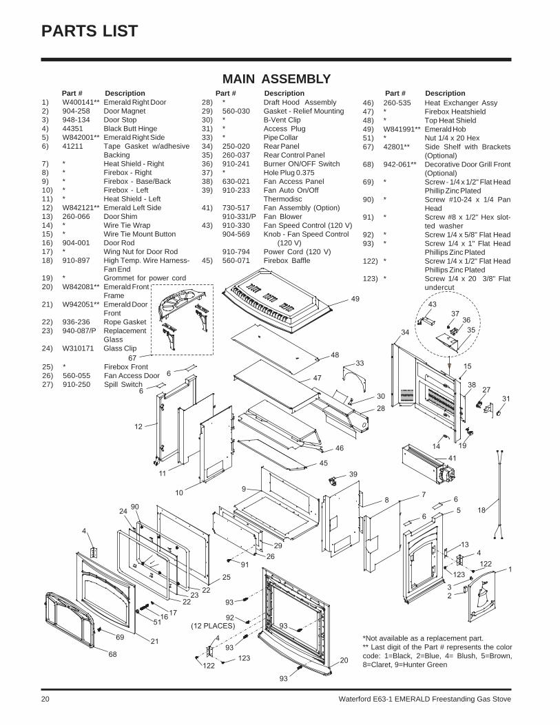
PARTS LIST
MAIN ASSEMBLY
1) W400141** Emerald Right Door2) 904-258 Door Magnet3) 948-134 Door Stop4) 44351 Black Butt Hinge5) W842001** Emerald Right Side6) 41211 Tape Gasket w/adhesive
Backing7) * Heat Shield - Right8) * Firebox - Right9) * Firebox - Base/Back10) * Firebox - Left11) * Heat Shield - Left12) W842121** Emerald Left Side13) 260-066 Door Shim14) * Wire Tie Wrap15) * Wire Tie Mount Button16) 904-001 Door Rod17) * Wing Nut for Door Rod18) 910-897 High Temp. Wire Harness-
Fan End19) * Grommet for power cord20) W842081** Emerald Front
Frame21) W942051** Emerald Door
Front22) 936-236 Rope Gasket23) 940-087/P Replacement
Glass24) W310171 Glass Clip
Part # Description Part # Description Part # Description28) * Draft Hood Assembly29) 560-030 Gasket - Relief Mounting30) * B-Vent Clip31) * Access Plug33) * Pipe Collar34) 250-020 Rear Panel35) 260-037 Rear Control Panel36) 910-241 Burner ON/OFF Switch37) * Hole Plug 0.37538) 630-021 Fan Access Panel39) 910-233 Fan Auto On/Off
Thermodisc41) 730-517 Fan Assembly (Option)
910-331/P Fan Blower43) 910-330 Fan Speed Control (120 V)
904-569 Knob - Fan Speed Control (120 V)
910-794 Power Cord (120 V)45) 560-071 Firebox Baffle
46) 260-535 Heat Exchanger Assy47) * Firebox Heatshield48) * Top Heat Shield49) W841991** Emerald Hob51) * Nut 1/4 x 20 Hex67) 42801** Side Shelf with Brackets
(Optional)68) 942-061** Decorative Door Grill Front
(Optional)69) * Screw - 1/4 x 1/2" Flat Head
Phillip Zinc Plated90) * Screw #10-24 x 1/4 Pan
Head91) * Screw #8 x 1/2" Hex slot-
ted washer92) * Screw 1/4 x 5/8" Flat Head93) * Screw 1/4 x 1" Flat Head
Phillips Zinc Plated122) * Screw 1/4 x 1/2" Flat Head
Phillips Zinc Plated123) * Screw 1/4 x 20 3/8" Flat
undercut
*Not available as a replacement part.** Last digit of the Part # represents the colorcode: 1=Black, 2=Blue, 4= Blush, 5=Brown,8=Claret, 9=Hunter Green
25) * Firebox Front26) 560-055 Fan Access Door27) 910-250 Spill Switch
Waterford E63-1 EMERALD Freestanding Gas Stove 21
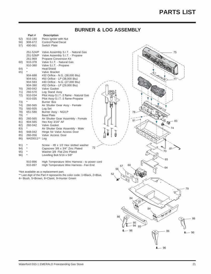
BURNER & LOG ASSEMBLY
52) 910-190 Piezo Igniter with Nut56) 908-672 Control Panel Decal57) 490-061 Switch Plate
251-524/P Valve Assembly S.I.T. - Natural Gas251-526/P Valve Assembly S.I.T. - Propane261-969 Propane Conversion Kit
60) 910-378 Valve S.I.T. - Natural Gas910-380 Valve S.I.T. - Propane
64) * Heat Shield65) * Valve Bracket
904-688 #32 Orifice - N.G. (38,000 Btu)904-641 #50 Orifice - LP (38,000 Btu)904-593 #40 Orifice - N.G. (27,000 Btu)904-390 #52 Orifice - LP (29,000 Btu)
70) 260-042 Valve Gasket71) 260-570 Log Stand Assy72) 910-034 Pilot Assy-S.I.T.-3 flame - Natural Gas
910-035 Pilot Assy-S.I.T.-3 flame-Propane73) * Burner Box74) 260-565 Air Shutter Gear Assy - Female75) 560-935 Log Set78) 651-580 Burner Assy - NG/LP79) * Base Plate80) 260-565 Air Shutter Gear Assembly - Female81) 904-565 Hex Key 3/16" AF82) 260-042 Valve Gasket83) * Air Shutter Gear Assembly - Male84) 948-042 Hinge for Valve Access Door85) 260-056 Valve Access Door86) W420011** Leg
91) * Screw - #8 x 1/2 Hex slotted washer94) * Capscrew 3/8 x 3/4" Zinc Plated95) * Washer 3/8 Flat Zinc Plated96) * Levelling Bolt 5/16 x 5/8"
910-896 High Temperature Wire Harness - to power cord910-897 HIgh Temperature Wire Harness - Fan End
*Not available as a replacement part.** Last digit of the Part # represents the color code: 1=Black, 2=Blue,4= Blush, 5=Brown, 8=Claret, 9=Hunter Green
Part # Description
PARTS LIST
22 Waterford E63-1 EMERALD Freestanding Gas Stove
_____________________________________________________________________________________
____________________________________________________________
__________________________________________________________
____________________________________________________________
_______________________________________________________
_____________________________________________________
__________________________________________________________
_________________________________________________________
_________________________________________________________
______________________________________________________
______________________________________________________
_______________________________________________________________
___________________________________________________________
__________________________________________________________
____________________________________________________________
____________________________________________________________
____________________________________________________________
_____________________________________________________________
__________________________________________________________
__________________________________________________________
_____________________________________________________
________________________________________________________
_________________________________________________________
_________________________________________________________
NOTES
Waterford E63-1 EMERALD Freestanding Gas Stove 23
WARRANTY
Waterford Fireplace Products are designed with reliability and simplicity in mind. In addition, our internal Quality Assurance Team carefully inspects eachunit thoroughly before it leaves our facility. FPI Fireplace Products International Ltd. is pleased to extend this limited lifetime warranty to the originalpurchaser of a Waterford Product.
The Warranty: Limited LifetimeExternal casting, not directly in contact with the fire, such as hobs, sides, ash lips, legs, fronts and fire doors, are covered against cracks and warps resulting frommanufacturer defects, parts and subsidized labour* for three (3) years from the date of purchase and parts only thereafter.
The combustion chamber, heat exchanger, burner tubes/pans, logs, embers and all gold plating (against defective manufacture only) are covered under the LimitedLifetime Warranty for five (5) years for parts and subsidized labour* and parts only thereafter.
Glass is covered for lifetime against thermal breakage only, parts and subsidized labour* for three (3) years and parts only thereafter from date of purchase.
Electrical and mechanical components such as blowers, switches, wiring, thermodiscs, FPI remote controls, spill switches, thermopiles, thermocouples, pilot assemblycomponents, and gas valves are covered for one year parts and subsidized labour* from the date of purchase. Blowers and valves replaced under warranty are consideredrepairs and continue as if new with appliance. ie. twelve (12) months from original purchase date of appliance with a minimum of three (3) months coverage from dateof replacement.
FPI venting components are covered parts and subsidized labour* for three (3) years from date of installation and parts only thereafter.
Conditions:Porcelain/Enamel - Absolute perfection is neither guaranteed nor commercially possible. Any chips must be reported and inspected by an authorized dealer within threedays of installation. Reported damage after this time will be subject to rejection.
Any part or parts of this unit which in our judgement show evidence of such defects will be repaired or replaced at FPI's option, through an accredited distributor or agentprovided that the defective part be returned to the distributor or agent Transportation Prepaid, if requested.
It is the general practice of FPI to charge for larger, higher priced replacement parts and issue credit once the replaced component has been returned to FPI and evaluatedfor manufacturer defect.
The authorized selling dealer is responsible for all in-field service work carried out on your Waterford product. FPI will not be liable for results or costs of workmanshipfrom unauthorized service persons or dealers.
At all times FPI reserves the right to inspect product in the field which is claimed to be defective.
All claims must be submitted to FPI by authorized selling dealers. It is essential that all submitted claims provide all of the necessary information including customername, purchase date, serial #, type of unit, problem, and part or parts requested, without this information the warranty will be invalid.
Exclusions:This limited Lifetime Warranty does not extend to or include paint (charcoal units), porcelain (including pinholes, scratches and minor shade mismatch), door or glassgasketing or trim.
At no time will FPI be liable for any consequential damages which exceed the purchase price of the unit. FPI has no obligation to enhance or modify any unit once manufactured.ie. as products evolve, field modifications or upgrades will not be performed.
FPI will not be liable for travel costs for service work.
Installation and environmental problems are not the responsibility of the manufacturer and therefore are not covered under the terms of this warranty policy.
Refractory liners, gaskets, door handles, paint are not covered under the terms of this warranty policy.
Any unit which shows signs of neglect or misuse is not covered under the terms of this warranty policy.
The warranty will not extend to any part which has been tampered with or altered in any way, or in our judgment has been subject to misuse, improper installation, negligenceor accident, spillage or downdrafts caused by environmental or geographical conditions, inadequate ventilation, excessive offsets, negative air pressure caused bymechanical systems such as furnaces, fans, clothes dryer, etc.
Freight damage to stoves and replacement parts is not covered by warranty and is subject to a claim against the freight carrier by the dealer.
FPI will not be liable for acts of God, or acts of terrorism, which cause malfunction of the appliance.
Performance problems due to operator error will not be covered by this warranty policy.
Products made or provided by other manufacturers and used in conjunction with the operation of this appliance without prior authorization from Waterford, may nullifyyour warranty on this product.
Simpson Dura-Vent venting components are covered by Simpson Dura-Vent Inc. warranty.
* Subsidy according to job scale as predetermined by FPI.

Installer: Please complete the following information
Dealer Name & Address:______________________________________________
__________________________________________________________________
Installer: ___________________________________________________________
Phone #: ___________________________________________________________
Date Installed: ______________________________________________________
Serial No.: _________________________________________________________
Printed in Canada
Waterford fireplace products aredesigned with reliability and simplicity
in mind. In addition, our internalQuality Assurance Team carefully
inspects each unit thoroughlybefore it leaves our door.
Waterford Irish Stoves is pleasedto extend this Limited Lifetime
Warranty to the original purchaser ofa Waterford Product.
See the inside back cover for details.
© FPI Fireplace Products International Ltd. 2003
Waterford is a trademark of FPI Fireplace Products International Ltd.