Embed Size (px)
Citation preview


-1-
REFERENCE BOOK ON
RECIPROCATING PUMPING
SYSTEM BASICS
(Year 2009 Edition)
Published By: Field Engineering Department
Oil India Limited
Compiled By:
C K Das, Dy SE-F Engg (ICE)
S Bhuyan, ME-F Engg (ICE)

-2-
PREFACE
If one delves a bit into the concept of the famous philosophy of “Continual Improvement”(also called incremental improvement or staircase improvement), it will be easily comprehensible that, the whole process of continual improvement revolves around the famous cycle of “Kaizen” (Japanese for continuous improvement) activity, ie: “Plan – Do - Check - Act”. The intent of this reference book is to act as a stepping stone for the “kaizen cycle” with respect to Reciprocating pumping Systems, by bringing together most of the aspects like basics of design, selection, installation, maintenance etc. This handbook is a result of our own basic learnings to understand the mechanical device called Reciprocating Pump. The materials in this book have been culled from varied sources and compiled together in an attempt to make a consolidated basic reference for users (with an emphasis on Plunger Type reciprocating pumps). Every attempt has been made to keep the contents of this reference book relevant to our organizational activities. We would like to thank and acknowledge Shri S E Mothilal, CE-FE (ICE-F&WI), Shri T B Chakraborty, Head- Field Engineering and Shri M J Bordoloi, Group General Manager-Engineering. This work would not have been possible without the guidance and encouragement received from them.
C K Das, Dy SE-F Engg (ICE) S Bhuyan, ME-F Engg (ICE)
Duliajan

-3-
CONTENTS
1. Chapter -1 : Introduction, Definition and Nomenclatures ------ 04
2. Chapter -2 : Basic Definitions ------ 18
3. Chapter -3 : Suction Requirements for Reciprocating Pumps ------ 20
4. Chapter-4 : Selection of Pumping Systems ------ 22
5. Chapter-5 : Important Auxiliary Equipments in a Reciprocating
Pumping System ------ 32
6. Chapter -6 : Installation of Reciprocating Pumps ------ 35
7. Chapter-7 : Maintenance and Operation practices
for Reciprocating Pump Sets ------ 42
Appendix-I : Material of Construction of Basic Plunger Pump, Components and Basics of Pump Packings
------ 46
Appendix-II : Sample Technical Specification for Procurement of Gas Engine Driven Reciprocating Pump
------ 49
Appendix-III : Details of Prominent OEMs
------ 62
Appendix-IV: Basics of Reciprocating Pump Plunger Lubricators
------ 64
Appendix-V: Format for Scheduled Inspection of Engine Driven
Reciprocating Pump sets ------ 66
Appendix- VI: Safe Operating Procedure and Guidelines for Operation of
Reciprocating Pumps ------ 69
Appendix-VII: Basics of Alignment ------ 70
Appendix- VIII: Basic Maintenance Schedule for Gear Boxes ------ 71
Bibliography ------72
--------
-4-
Chapter -1_______________________________________________________________________ Introduction, Definition and Nomenclatures
1.1 Introduction: A pump is a mechanical device used to increase the pressure energy of a liquid. This is usually achieved by creating a differential pressure at the inlet and a high pressure at the outlet ends of the pump. PUMP:
(i) Positive displacement pumps (Reciprocating, gear, screw pumps) (ii) Variable displacement pumps (centrifugal pumps)
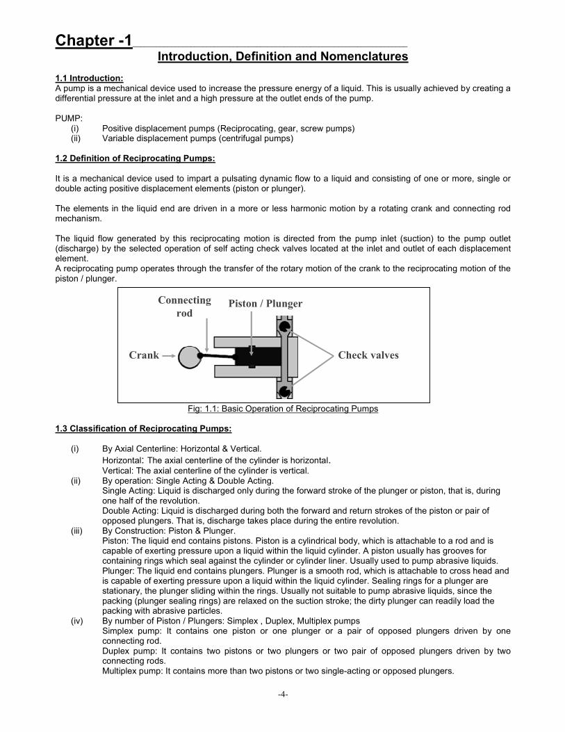
1.2 Definition of Reciprocating Pumps: It is a mechanical device used to impart a pulsating dynamic flow to a liquid and consisting of one or more, single or double acting positive displacement elements (piston or plunger). The elements in the liquid end are driven in a more or less harmonic motion by a rotating crank and connecting rod mechanism. The liquid flow generated by this reciprocating motion is directed from the pump inlet (suction) to the pump outlet (discharge) by the selected operation of self acting check valves located at the inlet and outlet of each displacement element. A reciprocating pump operates through the transfer of the rotary motion of the crank to the reciprocating motion of the piston / plunger.
Fig: 1.1: Basic Operation of Reciprocating Pumps 1.3 Classification of Reciprocating Pumps:
(i) By Axial Centerline: Horizontal & Vertical.
Horizontal: The axial centerline of the cylinder is horizontal. Vertical: The axial centerline of the cylinder is vertical.
(ii) By operation: Single Acting & Double Acting. Single Acting: Liquid is discharged only during the forward stroke of the plunger or piston, that is, during one half of the revolution. Double Acting: Liquid is discharged during both the forward and return strokes of the piston or pair of opposed plungers. That is, discharge takes place during the entire revolution.
(iii) By Construction: Piston & Plunger. Piston: The liquid end contains pistons. Piston is a cylindrical body, which is attachable to a rod and is capable of exerting pressure upon a liquid within the liquid cylinder. A piston usually has grooves for containing rings which seal against the cylinder or cylinder liner. Usually used to pump abrasive liquids. Plunger: The liquid end contains plungers. Plunger is a smooth rod, which is attachable to cross head and is capable of exerting pressure upon a liquid within the liquid cylinder. Sealing rings for a plunger are stationary, the plunger sliding within the rings. Usually not suitable to pump abrasive liquids, since the packing (plunger sealing rings) are relaxed on the suction stroke; the dirty plunger can readily load the packing with abrasive particles.
(iv) By number of Piston / Plungers: Simplex , Duplex, Multiplex pumps Simplex pump: It contains one piston or one plunger or a pair of opposed plungers driven by one connecting rod. Duplex pump: It contains two pistons or two plungers or two pair of opposed plungers driven by two connecting rods. Multiplex pump: It contains more than two pistons or two single-acting or opposed plungers.
Crank
Connecting
rod Piston / Plunger
Check valves

-5-
Fig: 1.2: Types of Reciprocating Pumps
1.4 Nomenclatures: [The texts and diagrams are guided by Hydraulic Institute Standards (HI 6.1-6.5). The Hydraulic Institute is an organization of pump manufacturers that has been in existence in the US since 1917. It has been successful in setting up Engineering Standards for Pumps of all types.] 1.4.1Description of components: The nomenclature and definitions appended below were prepared to provide a means for identifying the various pump components and also to serve as a common language for all who deal with this type of equipment. The following definitions and drawings illustrate typical construction of reciprocating power pump components but do not necessarily represent recommended designs. 1.4.1-(a) Right and left hand shaft extension of power pumps: "Right" or "left hand" designates the side of the power end from which the crankshaft or pinion shaft extends. (It does not designate in which direction the shaft rotates.) Horizontal power pumps are termed right hand or left hand as viewed when standing behind the power end with the liquid end being the most distant part. A left hand pump has the shaft extending out of the left side of the power end. A right hand pump has the shaft extending out of the right side of the power end. Vertical power pumps are termed right hand or left hand pumps as viewed when standing at and facing the suction manifold of the pump. A left hand pump has the shaft extending out of the left side of the power end. A right hand pump has the shaft extending out of the right side of the power end. 1.4.1-(b) Liquid/Fluid end: That portion of the pump which handles the liquid. It consists of a liquid cylinder, valves and other components. Liquid end parts
The following paragraphs describe major liquid end components. (i) Liquid cylinder A chamber(s) in which the motion of the plunger(s) or piston(s) is imparted to the liquid. The cylinder can be made integral with a suction and discharge manifold or can be made with separate manifolds. (ii) Cylinder liner A replaceable liner which is placed in the cylinder of a piston pump. The piston reciprocates within the liner. (iii) Manifolds A suction manifold is a chamber which accepts liquid from the suction port(s) and distributes it to the suction valves. A discharge manifold is a chamber which accepts liquid from the individual discharge valves and directs it to the discharge port(s). (iv) Valve chest cover

-6-
A cover for the valves within the cylinder. (v) Valve plate (valve deck) A plate that contains the suction or discharge valves. (vi) Piston A cylindrical body which is attachable to a rod and is capable of exerting pressure upon a liquid within the liquid cylinder. A piston usually has grooves for containing rings which seal against the cylinder or cylinder liner. A piston in a reciprocating pump is usually double-acting.
(vi) Plunger A smooth rod which is attachable to a crosshead and is capable of exerting pressure upon a liquid within the liquid cylinder. Sealing rings for a plunger are stationary, the plunger sliding within the rings. A plunger is single-acting, requiring a double-acting pump to have two plungers on each crosshead axis.
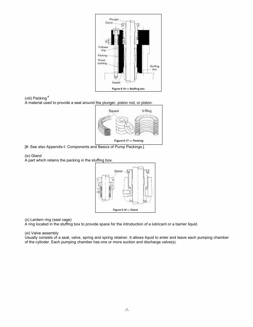
(vii) Stuffing box A cylindrical cavity through which the plunger or piston rod reciprocates and in which liquid leakage is controlled by means of packing. A follower ring and throat bushing are used to guide the plunger or rod as it reciprocates. The throat bushing and follower ring contain the packing within the stuffing box.
-7-
(viii) Packing
#
A material used to provide a seal around the plunger, piston rod, or piston.
[#: See also Appendix-I: Components and Basics of Pump Packings.]
(ix) Gland A part which retains the packing in the stuffing box.
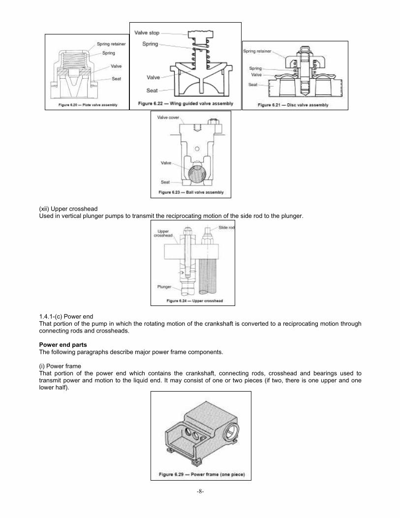
(x) Lantern ring (seal cage) A ring located in the stuffing box to provide space for the introduction of a lubricant or a barrier liquid. (xi) Valve assembly Usually consists of a seat, valve, spring and spring retainer. It allows liquid to enter and leave each pumping chamber of the cylinder. Each pumping chamber has one or more suction and discharge valve(s).
-8-
(xii) Upper crosshead Used in vertical plunger pumps to transmit the reciprocating motion of the side rod to the plunger.
1.4.1-(c) Power end That portion of the pump in which the rotating motion of the crankshaft is converted to a reciprocating motion through connecting rods and crossheads. Power end parts
The following paragraphs describe major power frame components. (i) Power frame That portion of the power end which contains the crankshaft, connecting rods, crosshead and bearings used to transmit power and motion to the liquid end. It may consist of one or two pieces (if two, there is one upper and one lower half).
-9-
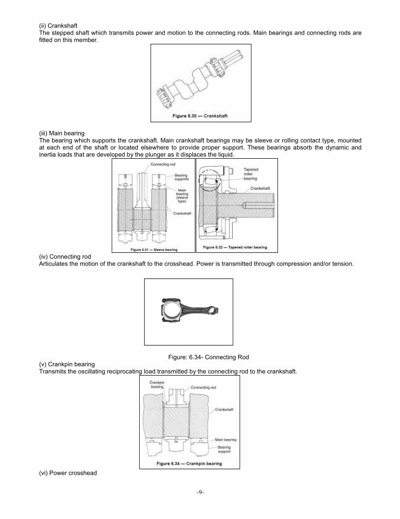
(ii) Crankshaft The stepped shaft which transmits power and motion to the connecting rods. Main bearings and connecting rods are fitted on this member.
(iii) Main bearing The bearing which supports the crankshaft. Main crankshaft bearings may be sleeve or rolling contact type, mounted at each end of the shaft or located elsewhere to provide proper support. These bearings absorb the dynamic and inertia loads that are developed by the plunger as it displaces the liquid.
(iv) Connecting rod Articulates the motion of the crankshaft to the crosshead. Power is transmitted through compression and/or tension.
Figure: 6.34- Connecting Rod (v) Crankpin bearing Transmits the oscillating reciprocating load transmitted by the connecting rod to the crankshaft.
(vi) Power crosshead

-10-
Creates a linear reciprocating motion derived from the crankpin rotary motion through the connecting rod. The reciprocating motion of the crosshead is applied to the plunger or piston via the side rods or crosshead extension.
(vii) Gudgeon/ Wrist pin Connects the connecting rod to the crosshead . (viii) Gudgeon/ Wrist pin bearing Transmits the reciprocating load of the crosshead into the connecting rod .
(ix) Crosshead extension (plunger extension) Connects the crosshead to the plunger.
(x) Frame extension Connects the liquid end to the power frame when the liquid end is not bolted directly to the frame. A horizontal extension is sometimes called a cradle.
1.5 Composite Drawings: Appended on the following pages, are a few drawings of reciprocating pump liquid (fluid) end and power ends with assembled components described above.

-11-

-12-

-13-

-14-
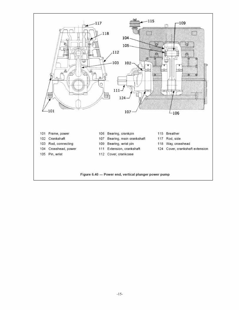
-15-

-16-

-17-
(See also Appendix-I: Material of Construction of Basic Plunger Pump Components and Basics of pump Packings
#)
--------

-18-
Chapter -2___________________________________________________________________________ Basic Definitions
Appended below are a few basic definitions guided by Indian Standard 11745 for reference of the users: 2.1 General Terminology:
2.1 .I Power pump - is a reciprocating pump driven by power from an outside source applied to the crank shaft of the pump. 2.1.2 Piston or plunger load- is the force acting on one plunger or piston during any portion of the pumping cycle. 2.1.3 Maximum allowable speed (RPM)*- is the highest speed at which the manufacturer’s design shall permit continuous operation. 2.1.4 Minimum allowable speed ( RPM ) -The lowest speed of which the manufacturer’s designs shall permit continuous operation. 2.1.5 Maximum allowable temperature -The maximum continuous temperature when handling the specified fluid at the specified pressure. 2.1.6 Maximum allowable working pressure -The maximum continuous pressure for which the manufacturer has designed the equipment, when handling the specified fluid of the specified temperature and capacity. 2.1.7 Rated discharge pressure -The discharge pressure of the pump having a rated capacity, speed, suction pressure, specific gravity and viscosity. 2.1.8 Vapour pressure - Every liquid at any temperature above its freezing point exerts a pressure due to formation of vapour at its free surface. This pressure is known as the vapour pressure of the liquid. 2.1.9 Rated capacity- is the total volume of fluid actually delivered per unit of time at the stated operating conditions, this includes both liquid and any dissolved or entrained gases. 2.2 Ratings- The following terms are used to designate (or are used in connection with) pump rating. These ratings are determined by pump design and not by conditions of specific application. 2.2.1 Pump efficiency (mechanical efficiency) It is the ratio of the pump power output to the pump power input.
ηp = Po/ Pi
where, Po = pump power output Pi = pump power input 2.2.2 Volumetric efficiency- The ratio of the pump suction capacity to pump displacement and is expressed as a percentage and calculated as follows:
ηv = Q/D
where, Q = pump suction capacity D = pump displacement (See Chapter-4: Selection of Pumping System also) 2.2.3 Net positive suction head (NPSH) - is the total suction head of liquid in metres absolute. 2.2.3.1 Available net positive suction head (NPSHa)-The total suction head, deducting, system acceleration head, available at the pump suction connection, minus the vapour head (vapour pressure -converted in head) of the liquid of pumping temperature. This is expressed in metre.

-19-
2.2.3.2 Required net positive suction head (NPSHr) - The total suction head, including pumps acceleration head, required by the pump at the pump suction connection, minus the vapour pressure of the liquid of pumping temperature. This is expressed in metre. 2.2.4 Acceleration head (ha)-The pressure changes due to changes in velocity in the piping system and may be calculated as follows:
2.2.5 Friction head-The hydraulic pressure exerted to overcome friction resistance of a piping system to liquid flow. 2.2.6 Static head -The hydraulic pressure exerted at the pump ,by the liquid at rest. 2.2.7 Flooded suction - Implies that the liquid shall flow from an atmosphere vented source to the pump without the average pressure at the intake port of the pump, dropping below atmosphere pressure with the pump operating at specified capacity. 2.2.8 Static suction lift (hss)-The hydraulic pressure below atmospheric of the intake port of the pump with the liquid at rest. It is usually expressed in millimeter of mercury vacuum. 2.2.9 Total suction head (hs) - The total hydraulic pressure above atmospheric at the intake port while the pump is in operation and is the difference between the intake static head and the intake friction head. 2.2.10 Total suction lift (hsj-The total hydraulic pressure below atmospheric of the intake port while the pump is in operation. The sum of the static suction lift plus the intake friction head or the difference between the intake friction head and the static suction head. 2.2.11 Total discharge head (hd)-The total hydraulic pressure at the discharge port while the pump is in operation and is the sum of the discharge static head and the discharge friction head. 2.2.12 Total head (h)-The difference between the total discharge head and total suction head, or the sum of the total discharge head and total suction lift head.
* Table – 1 of API Std 674 provides the standard Maximum allowable speed ratings for power pumps in continuous service.
--------
-20-
Chapter -3___________________________________________________________________________ Suction Requirements for Reciprocating Pumps
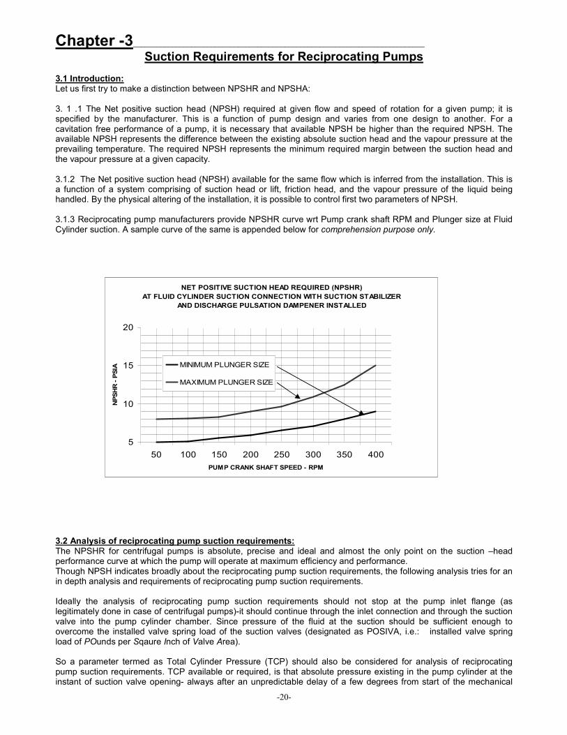
3.1 Introduction: Let us first try to make a distinction between NPSHR and NPSHA: 3. 1 .1 The Net positive suction head (NPSH) required at given flow and speed of rotation for a given pump; it is specified by the manufacturer. This is a function of pump design and varies from one design to another. For a cavitation free performance of a pump, it is necessary that available NPSH be higher than the required NPSH. The available NPSH represents the difference between the existing absolute suction head and the vapour pressure at the prevailing temperature. The required NPSH represents the minimum required margin between the suction head and the vapour pressure at a given capacity. 3.1.2 The Net positive suction head (NPSH) available for the same flow which is inferred from the installation. This is a function of a system comprising of suction head or lift, friction head, and the vapour pressure of the liquid being handled. By the physical altering of the installation, it is possible to control first two parameters of NPSH. 3.1.3 Reciprocating pump manufacturers provide NPSHR curve wrt Pump crank shaft RPM and Plunger size at Fluid Cylinder suction. A sample curve of the same is appended below for comprehension purpose only.
3.2 Analysis of reciprocating pump suction requirements: The NPSHR for centrifugal pumps is absolute, precise and ideal and almost the only point on the suction –head performance curve at which the pump will operate at maximum efficiency and performance. Though NPSH indicates broadly about the reciprocating pump suction requirements, the following analysis tries for an in depth analysis and requirements of reciprocating pump suction requirements. Ideally the analysis of reciprocating pump suction requirements should not stop at the pump inlet flange (as legitimately done in case of centrifugal pumps)-it should continue through the inlet connection and through the suction valve into the pump cylinder chamber. Since pressure of the fluid at the suction should be sufficient enough to overcome the installed valve spring load of the suction valves (designated as POSIVA, i.e.: installed valve spring load of POunds per Sqaure Inch of Valve Area). So a parameter termed as Total Cylinder Pressure (TCP) should also be considered for analysis of reciprocating pump suction requirements. TCP available or required, is that absolute pressure existing in the pump cylinder at the instant of suction valve opening- always after an unpredictable delay of a few degrees from start of the mechanical
NET POSITIVE SUCTION HEAD REQUIRED (NPSHR)
AT FLUID CYLINDER SUCTION CONNECTION WITH SUCTION STABILIZER
AND DISCHARGE PULSATION DAMPENER INSTALLED
5
10
15
20
50 100 150 200 250 300 350 400
PUMP CRANK SHAFT SPEED - RPM
NPSHR - PSIA MINIMUM PLUNGER SIZE
MAXIMUM PLUNGER SIZE
-21-
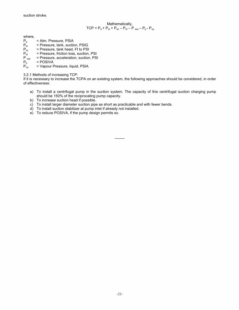
suction stroke.
Mathematically, TCP = Pa + Pst + Psz – Psf – P sac – Pp - Pvp
where, Pa = Atm. Pressure, PSIA Pst = Pressure, tank, suction, PSIG Psz = Pressure, tank head, Ft to PSI Psf = Pressure, friction loss, suction, PSI P sac = Pressure, acceleration, suction, PSI Pp = POSIVA Pvp = Vapour Pressure, liquid, PSIA 3.2.1 Methods of increasing TCP: If it is necessary to increase the TCPA on an existing system, the following approaches should be considered, in order of effectiveness:
a) To install a centrifugal pump in the suction system. The capacity of this centrifugal suction charging pump should be 150% of the reciprocating pump capacity.
b) To increase suction head if possible. c) To install larger diameter suction pipe as short as practicable and with fewer bends. d) To install suction stabilizer at pump inlet if already not installed. e) To reduce POSIVA, if the pump design permits so.
--------

-22-
Chapter -4___________________________________________________________________________ Selection of Pumping System
4.1 Introduction: The following chapters are intended to guide the users in selection of duty / service of reciprocating pumps and also to guide about the guiding statutory standards in selection of reciprocating pumping systems. 4.2 Definition of Pump Duty/ Service: Hydraulic Institute Standards (HI 6.1-6.5) define Duty/ Service of Reciprocating Pumps as below,
a) Continuous Duty: 8 to 24 hours per day, fully loaded. (In intervals of inspection recommended by the OEMs) b) Light Duty: 3 to 8 hours per day, fully loaded. c) Intermittent duty: Up to 3 hours per day, fully loaded. d) Cyclical Operation: ½ minute loaded out of every 3 minutes.
While selection of reciprocating pumps the duty condition is of utmost importance. Hence as per site requirements pumps should be selected as per the above HI standard recommendations. 4.3 Statutory Standards: The selection of reciprocating pumping system should be guided by the following standards:
a) Hydraulic Institute Standards (HI 6.1-6.5). b) American Petroleum Institute Standards- API- 674.
c) NEC: National Electrical Code.
d) NEMA: National Electrical Manufacturers’ Association.
e) IEC: International Electro technical Commission.
f) OISD – 113: Standard on classification of area for electrical installations at hydrocarbon and handling facilities.
g) DGMS latest notifications. h) Indian Standard- IS: 11745.
4.4 Some Basic Definition:
The following definitions are intended to act as a guide for calculation of necessary data wrt Reciprocating pump
selection: [The texts are guided by Hydraulic Institute Standards (HI 6.1-6.5)]
4.4.1 Stroke: One complete uni directional motion of piston or plunger. Stroke length is expressed in inches.
4.4.2 Pump Capacity (Q): The capacity of a reciprocating pump is the total volume through put per unit of time at
suction condition. It includes both liquid and any dissolved or entrained gases at the stated operating condition.
4.4.3 Pump Displacement (D): The displacement of a reciprocating pump is the volume swept by all pistons or
plungers per unit time. Deduction for piston rod volume is made on double acting piston type pumps when calculating
displacement.
For single acting pumps:
D = A s n m / 231
For double acting piston pumps with no tail – rod(s):
D = (2A-a) s n m / 231
where, A = Plunger or piston area in sq inch

-23-
a = piston rod cross sectional area (double acting pump) in sq inch
s = stroke length in inch
n = RPM of crank shaft
m = number of pistons or plungers
4.4.4 Plunger or Piston speed (v): The plunger or piston speed is the average speed pf the plunger or piston.(in feet
per minute)
v = (n X s) / 6
4.4.5 Pressures:
Discharge Pressure (pd): The liquid pressure at the center line of the pump discharge port.
Suction pressure (ps): The liquid pressure at the center line of the pump suction port.
Differential Pressure (ptd): The difference between the liquid Discharge Pressure and Suction pressure.
Net Positive Suction head required (NPSH): The amount of suction pressure, over vapour pressure, required by the
pump obtain satisfactory volumetric efficiency and prevent excessive cavitations.
4.4.6 Slip: Slip of a reciprocating pump is the loss of capacity, expressed as a fraction or percent of displacement, due
to leaks past the valves (including the back flow through the valves caused by delayed closing) and past double acting
piston. Slip does not include luid compressibility or leaks from the liquid end.
4.4.7 Power:
Pump Power input (Pi): The mechanical power delivered to the pump input shaft, at the specified operating conditions.
Input horsepower may be calculated as follows,
Pi = (Q X Ptd) / (1714 X ηp)
where, Q = Pump Capacity (GPM)
ptd = Differential Pressure (psi)
ηp = Pump (mechanical efficiency)
Pump Power Output (P0): The hydraulic power imparted to the liquid by the pump at the specified operating
conditions. Output horsepower may be calculated as follows,
P0 = Q X Ptd / 1714
Example: Pump Prime Mover Selection Let us consider a pump with rated Discharge: 40 KLpH at 60 Kg/cm
2 Pressure.
So Pump Power input (Pi) = Pi = (Q X Ptd) / (1714 X ηp)
Q= 176 gpm
Ptd= 853 psi ηp = 80% PI = 109.5 HP Considering FOS = 1.25, PI = 137 HP So the prime mover for the said pump should be selected such that, it is capable of developing minimum 137 HP in addition to compensation for PTO and other transmission system losses.

-24-
4.5 Gear Box Selection:
4.5.1: Gear box selection
The following steps are to be followed for selection / validation of gear boxes for reciprocating pumping systems:
4.5.1.1. Determination of gear unit type and size:
I. Find the transmission ratio is = n1 / n2
II. Determine nominal power rating of the gear unit P2N ≥ P2 x f1 x f2
III. Check for maximum torque, e. g. peak operating-, starting- or braking torque
Where, is = Required ratio n1 = Input speed (rpm) n2 = Output speed (rpm) P2N = Nominal power rating of gear unit (kW), see ratings (Table 1) P2 = Power rating of driven machine (kW) f1 = Factor for driven machine (table 3) f2 = Factor for prime mover (table 2) f3 = Peak torque factor (table 4)
TA = Max. torque occurring on input shaft, e.g. peak operating-, starting- or braking torque (Nm) 4.5.1.2. Determination of oil supply: 2.1 Horizontal: All parts to be lubricated are lying in the oil or are splash lubricated. 2.2 Vertical: Possible oil supply variations:
– Dip lubrication – Forced lubrication by means of flanged-on pump or motor pump
4.5.1.3. Determination of required thermal capacity, PG: Data required:
– Type – Size – Nominal ratio – Ambient temperature – Input speed (1000 / 1200 / 1500 / 1800 min-1) – Lubrication
After obtaining the above the data the thermal capacity can be validated from manufacturers’ tables keeping in consideration that,
PG >= P2 (for all cases)

-25-
Nominal power rating of gear unit Table- 1

-26-
Factor for prime mover: Table -2
Factor for Driven Machine: Table -3
Peak torque factor: Table -4
4.6 PTO Clutch Selection:
The power take-off is a device which is used between the prime mover and the driven unit. It acts as a coupling device with a disconnect function, which is necessary for the following reasons: • For the starting of the engine without load • For connecting the load to the engine, as and when required without stopping the engine. • To facilitate the running of one or both units simultaneously. There are a variety of industrial applications which involve a high start-up inertia. In these cases, Power Take-Offs are used to separate the diesel engine from the driven unit. When the engine attains full operating speed the unit is connected to the engine through the power take off.
The following data should be taken into consideration for selection of a PTO clutch unit wrt an engine driven pumping
system,

-27-

-28-

-29-
-30-
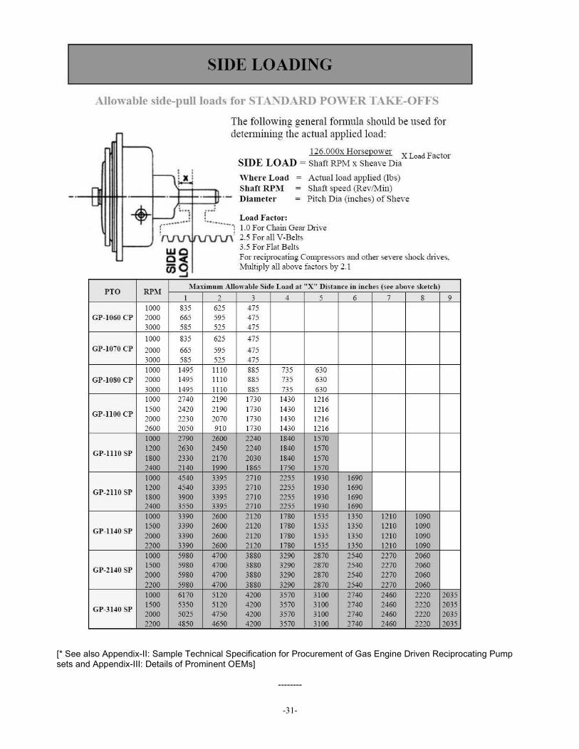
-31-
[* See also Appendix-II: Sample Technical Specification for Procurement of Gas Engine Driven Reciprocating Pump sets and Appendix-III: Details of Prominent OEMs]
--------

-32-
Chapter -5___________________________________________________________________________ Important Auxiliary Equipments in a Reciprocating Pumping System
5.1 Safety/ Pressure Relief Valve For protection of the system, the reciprocating pump must be equipped with a pressure relief device that relieves the system of all pressures which exceeds the pump discharge pressure ratings. Recommended Set pressures for Safety/ Pressure Relief Valves:
Pump Type Set pressure
Duplex Double acting Piston pressure rating + 25%
Triplex single acting Piston pressure rating + 10%
Quintuplex – Single acting Piston pressure rating + 10%
5.1.1 Types:
• Shear Relief Type: This type of pressure relief valve utilizes shear pins to relieve over pressure from pumping systems. As soon as the system pressure exceeds the rated pressure the shear pin shears and actuates the spindle to release the system from the pressure overshoot condition.
The rating of such relief valves can be set by altering the shear pins.
• Reset Relief type:
The Model RR relief valve automatically snaps to a full open position when the predetermined pressure is exceeded or can be manually opened by simply pressing the manual release button. And the position of the release button indicates at a glance whether the valve is open or closed.
The model RR is designed with a pressure setting indicator which can be adjusted to any setting within the operating range by simply turning a nut on the top of the valve. 5.1.2 Features of safety relief valve
• The valve must be a full opening type. • It must have working pressure rating equal to or greater than the maximum working pressure of pump. • The through capacity of the valve when fully open must be sufficient to relieve the full capacity of the pump
without excessive over pressure.
5.1.3 Location • The relief must be placed in the discharge line as close as possible to the pump fluid end or it may be

-33-
mounted on the pump discharge manifold. • The relief valve must be on the pump side of any discharge strainer. • Relief valve must be between pump fluid and any valve in the discharge system. • There must be no restricting device between the relieve valve and the pump fluid end.
5.1.4 Installation of discharge line relief valve
• Relief valve discharge line should not terminate in the pump suction side but should terminate in the supply tank.
• The line must be securely anchored. • The line must be of the same size or greater than the discharge connection on the safety relief valve. • If the line is of great length, this must be taken into consideration in sizing the relief valve.
5.2 Suction Stabilization
One can easily comprehend that without a sufficient supply of fluid a pump will not perform efficiently. Fluid "starvation" is caused by unbalanced hydraulics from friction, acceleration, and head. A reciprocating pump further complicates the issue by emitting high-frequency pressure waves created by the inlet valves opening and closing. More often, though, the problem is one of partial or complete cavitations. A little known phenomenon called acceleration head relates directly to the acceleration of fluid velocity on each stroke of the pump, a factor not seen in laminar flows with rotary PD pumps and centrifugal pumps. Suction Stabilization can be achieved by use of an auxiliary reservoir of low velocity liquid, at the pump inlet for the instantaneous accelerated demand of each pumping stroke . Two types of such devices are used:
• Volume Bottles • Dampener with Internal Baffles
5.2.1 Volume Bottles: The simplest form of pulsation dampener is a volume bottle, sometimes called a surge drum. A volume bottle is a pressure vessel without internal baffles and is usually mounted directly to the pump connection. A generally accepted formula for determining the size of volume bottles for application up to 600 psi, is 5 times the cylinder swept volume for discharge bottle, and 7.5 times cylinder swept volume for suction bottle. Benefits:
• Ease of Construction • Low Pressure Drop
Disadvantages: • Difficulty in accurately predicting pulsation levels
5.2.2 Dampener with Internal Baffles: A pulsation dampener with internal baffles, is much more predictable in it's performance since its design takes into account specific duty, including speed and fluid composition. Care must be taken to arrive at the optimum pulsation dampening level without creating unacceptable pressure drops. This type of dampener can typically limit pressure pulsation to within + or - 2% of absolute pressure while at the same time limiting pressure drop to 1% of absolute pressure. In a bladder type pulsation dampener, dry nitrogen is the gas of choice. It is readily available and, being oxygen free, it prolongs bladder life. 5.2.3 Comparative curves showing effect of suction stabilization is appended below for comprehension of users,
5.3 Discharge Pulsation Dampening: Even after fulfilling the requirements of the suction system, there will still exist pulsations caused by a reciprocating pump, because of its shear design. Positive displacement pumps create pulsation and hydraulic shock purely by the reciprocating nature of the pump's stroking action. A discharge pulsation dampener if installed in the delivery line of a

-34-
reciprocating pump, provides the following advantages: • Absorbs pressure variations • Reduces peak pressure • Permits slightly higher pump out put. • Increases overall system life.
Pulsation dampeners with internal baffles or bladders is suitable for Discharge Pulsation Dampening. 5.3.1 Dampener Operation#: During the discharge stroke of a pump, fluid pressure takes the line of least resistance, displacing the bladder in the dampener, thus compressing the trapped gas. As the pump begins its next cycle, fluid flow stops momentarily allowing the compressed gas to expand, forcing the bladder to push the accumulated fluid back into the discharge line filling the void created by the pump's cycle shift. Whether a piston or plunger a Pulsation Dampener placed at the pump's discharge will produce a steady fluid flow up to 99% pulsation free; protecting the entire pumping system from the damaging effects of shock.
5.4 Pressure variation in different types of reciprocating pumps:
# The pressure of the inert gas in the dampener should be atleast 40% of the Mean Pump Pressure. [*See also Appendix-IV: Basics of Reciprocating Pump Plunger Lubricators]
--------

-35-
Chapter -6___________________________________________________________________________ Installation of Reciprocating Pumps
6.1 Introduction: The following paragraphs try to broadly identify some basic guidelines wrt installation of reciprocating pumps. Actual installation may vary within the recommended guidelines as per site conditions.
Fig: 6.1: Recommended Schematic Layout of a Reciprocating Pump
-36-
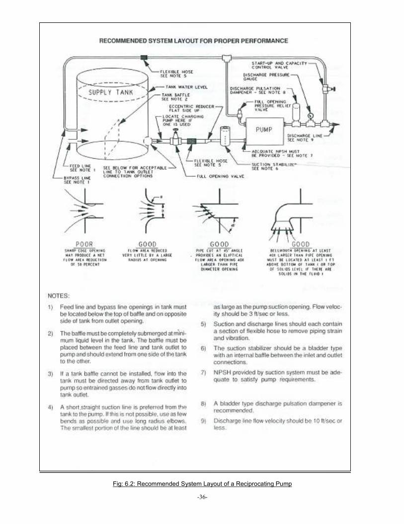
Fig: 6.2: Recommended System Layout of a Reciprocating Pump

-37-
Fig: 6.2: Reciprocating Pumping System: Good Design versus Poor Design
6.2 Inlet / Suction System: An inlet system for reciprocating pump must provide a flow of liquid at a relatively constant pressure to the pump, at pressure sufficient to meet NPSH and TCP requirements. For that purpose the following guidelines may be adhered to, 6.2.1 If a pump suction is to be connected to a manifold, the manifold or the suction pipe should have cross sectional area equal to or greater than the sum of the cross sectional areas of the inlet connections of individual pumps. 6.2.2 Inlet pipe diameter should be at least equal to or preferably greater than the pump inlet connection. 6.2.3 The suction valve should be full opening type. 6.2.4 Shortest Route from tank to pump should be selected.

-38-
6.2.5 All bend should be 45° long radius bends. 6.2.6 Supercharging: Use of centrifugal pumps to boost / charge the suction line to keep the pump from suction starvation is a successful method of correcting reciprocating pump suction problems. Charging pump used in suction line must have a minimum capacity equal to 1.5 times of the pump output. 6.2.7 Suction Stabilizer should be installed as close to the pump suction as practical. 6.3 Discharge system:
The Discharge system should provide smooth flow of pumped liquid free from pulsations ensuring extended pump and system life. The Discharge system should also be equipped with suitably rated pressure relief and bypass arrangements. 6.3.1 A bladder type discharge pulsation dampener should be installed right at the discharge point of the pump. 6.3.2 For protection of the system, the reciprocating pump must be equipped with a pressure relief device that relieves the system off all pressures which exceeds the pump discharge pressure ratings. 6.3.3 A suitably rated bypass (see 6.4 also) arrangement going back to the suction tank must installed to start the pump without load. 6.3.4 A suitably rated pressure gauge (Liquid surrounding gauge) should be installed at the pump discharge. 6.3.5 Non return (check) valve must be installed to protect the system from back pressures. 6.3.6 The discharge valve should be full opening type. (Preferably rising spindle type, thus visually indicating whether the valve is in closed or open position) 6.3.7 All bend should be 45° long radius bends. 6.3.8 All the pipings must be suitably anchored.
6.4 Importance of Liquid By pass System in Starting of Reciprocating pumps: While starting of a reciprocating pump, the liquid by pass line is of immense importance. Liquid by pass is the suitably rated arrangement from the pump discharge piping going back to the suction tank to facilitate starting of the pump without load. 6.4.1 The following considerations will help in comprehension of a liquid by pass arrangement,
• The starting torque required for a reciprocating pump is related to the mechanical inertia of the pump, couplings, gears, inertia of the prime mover and all the liquid in the pump suction line, bypass lines.
• While starting, all the liquid in the lines must be accelerated from standstill to full rated liquid velocities. • The torque needed to accelerate the entire mechanical hydraulic inertia system depends on the inertia of all
the moving parts (including liquid) and the rate of acceleration, plus total system friction. (Starting torque is directly proportional to the rate of acceleration).
• A liquid by pass line returning to the suction tank will not only facilitate release of any entrapped air/ gas in the suction system, but will reduce the torque required for starting pumping.
6.4.2 Starting a reciprocating pump without proper liquid bypass may cause the followings: • The pump will require excessive torque to start pumping at rated condition. • Reduce the life of power end bearings and other pump and drive components • May prevent complete priming of the liquid end resulting in rough operation and reduced
capacity. 6.4.2.1 In case of multiple pump applications (ie: Running of more than one pump in tandem), starting without proper
liquid bypass will result in: • Very high torque requirement, since the driver must accelerate itself , couplings, gears, pump
crankshaft, Con rods, cross heads, and plungers additionally it must also accelerate all the liquid in pump suction and discharge line.
• It must also develop the torque required to move the plungers or pistons against the line pressure already present.
6.4.2.2 In case of single pump applications , starting without proper liquid bypass will result in: • Forcing the pump to accelerate whole the liquid though the entire discharge system from
-39-
standstill. 6.5 Safety Recommendations in a reciprocating pumping system:
The important to safety shut down controls to be provided in a reciprocating pumping system are illustrated in tabular form below:
Indication/ Malfunction
Causes Result
Low suction pressure at suction manifold
Improper piping design, failure of charge pump etc.
Suction starvation, thus leading to knock in the pump.
Low discharge pressure
Worn piston/ plunger, worn packing, defective valves etc.
Failure of fluid end parts.
High discharge pressure
Restrictions in discharge piping. Making the whole system vulnerable to pressures higher than rated pressures
Low Lube oil pressure
Failure of Lube oil pump assembly, worn out pressure ring etc.
Improper lubrication of power end parts like bearings etc. thus leading to pre mature failure of rotating components like crank shaft, con rod, bearings etc.
Over speeding of prime mover
Faulty Governor pre mature failure of rotating components like crank shaft, con rod, bearings etc.
Excessive vibrations
Misalignment, loose foundation bolts etc.
Pre mature failure of rotating components like couplings, bearings etc.
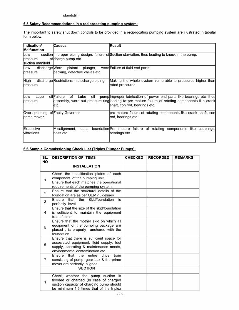
6.6 Sample Commissioning Check List (Triplex Plunger Pumps):
SL. NO
DESCRIPTION OF ITEMS CHECKED RECORDED REMARKS
INSTALLATION
1
Check the specification plates of each component of the pumping unit Ensure that each matches the operational requirements of the pumping system
2 Ensure that the structural details of the foundation are as per OEM guidelines
3 Ensure that the Skid/foundation is perfectly level
4 Ensure that the size of the skid/foundation is sufficient to maintain the equipment free of strain
5
Ensure that the mother skid on which all equipment of the pumping package are placed , is properly anchored with the foundation
6
Ensure that there is sufficient space for associated equipment, fluid supply, fuel supply, operating & maintenance needs, environmental contamination etc
7 Ensure that the entire drive train consisting of pump, gear box & the prime mover are perfectly aligned .
SUCTION
1
Check whether the pump suction is flooded or charged (In case of charged suction capacity of charging pump should be minimum 1.5 times that of the triplex
-40-
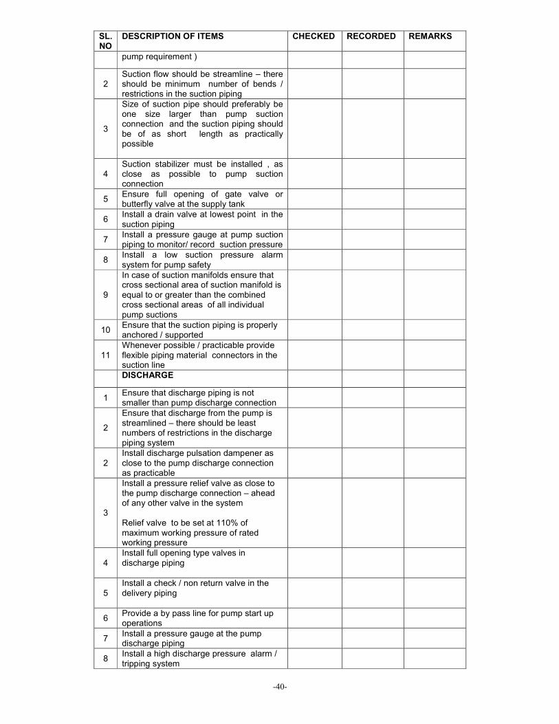
SL. NO
DESCRIPTION OF ITEMS CHECKED RECORDED REMARKS
pump requirement )
2 Suction flow should be streamline – there should be minimum number of bends / restrictions in the suction piping
3
Size of suction pipe should preferably be one size larger than pump suction connection and the suction piping should be of as short length as practically possible
4 Suction stabilizer must be installed , as close as possible to pump suction connection
5 Ensure full opening of gate valve or butterfly valve at the supply tank
6 Install a drain valve at lowest point in the suction piping
7 Install a pressure gauge at pump suction piping to monitor/ record suction pressure
8 Install a low suction pressure alarm system for pump safety
9
In case of suction manifolds ensure that cross sectional area of suction manifold is equal to or greater than the combined cross sectional areas of all individual pump suctions
10 Ensure that the suction piping is properly anchored / supported
11 Whenever possible / practicable provide flexible piping material connectors in the suction line
DISCHARGE
1 Ensure that discharge piping is not smaller than pump discharge connection
2
Ensure that discharge from the pump is streamlined – there should be least numbers of restrictions in the discharge piping system
2 Install discharge pulsation dampener as close to the pump discharge connection as practicable
3
Install a pressure relief valve as close to the pump discharge connection – ahead of any other valve in the system Relief valve to be set at 110% of maximum working pressure of rated working pressure
4 Install full opening type valves in discharge piping
5 Install a check / non return valve in the delivery piping
6 Provide a by pass line for pump start up operations
7 Install a pressure gauge at the pump discharge piping
8 Install a high discharge pressure alarm / tripping system

-41-
SL. NO
DESCRIPTION OF ITEMS CHECKED RECORDED REMARKS
PREPARATION FOR OPERATION
1 Check the pumping unit for any visual damage / defects
2 Check & align of the entire drive train
3 Check proper tension of all belts / chains,
4 Check all piping for proper anchoring / visible leaks
5 Check installed safety devices for proper operation
6 Check all foundation bolts & coupling bolts
FLUID END
1
Remove valve covers , inspect valve assemblies & service interior of fluid end Check plunger / piston rod connections and condition of gland packings
POWER END
1
Check direction of rotation of pump & ensure that it matches that of the prime mover. ( Pump is normally designed for clockwise rotation of crankshaft when viewed from right hand side. Right left determined by standing at the power end and looking towards fluid end.)
2
Check and clean the crank case of the pump for any dirt, foreign material, water, etc prior to filling with the right grade of lubricating oil . Check lubricating oil drive systems for leaks/ looseness if any
3 Ensure correct amount of lubricant in the crankcase (as per OEM guidelines )
[*See also Appendix- VII: Basics of Alignment]
--------
-42-
Chapter -7___________________________________________________________________________ Maintenance and Operation practices for
Reciprocating Pump sets
The following points are intended as a guide to be used in setting up a maintenance program. Good preventive maintenance will pay big dividends in the form of reliable service with a minimum of trouble. 7.1 Daily Maintenance: i. Check power end oil level daily by means of the dipstick in the rear cover. Do not attempt to check the oil with the
pump running. Inspect the oil for dirt or contamination and changed if necessary. An increase in oil level indicates fluid end leakage into power end. Change oil immediately and check intermediate rod wipers and surface smoothness of the rod. Check for plunger packing leakage.
ii. Lubricate plunger packing frequently. Packing life can be greatly increased by greasing every four (4) hours with a small amount of grease. Grease is not recommended at pressure above 1200psi. Use an alternate packing lubricator to drip the proper oil of the plunger for lubrication.
iii. Check lubricator for proper level and operation. iv. Check plunger packing for excessive leakage. Replace packing as required. v. Check stuffing box adjusting nuts for tightness. vi. Drain plunger leakage sump tanks if required. vii. Flush plunger chamber drain lines with kerosene on power oil pumps and fresh water on salt pumps. This may be
done weekly unless salt and paraffin accumulation is severe. viii. Make sure suction and discharge line valves are fully open. ix. Check for leakage between the fluid cylinder and frame or stuffing box to fluid cylinder packing if required. x. Check all seal for leakage. xi. Check belts or clutch for slippage. If either condition exists, correct immediately.
7.2 Monthly Maintenance:
i. Drain and refill crankcase every six (6) months or as often as required to maintain a clean, sludge-free oil of the proper viscosity.
ii. Clean crankcase air breather with a non- explosive solvent. iii. Check all studs, nuts and cap screws for tightness. Inspect gasket for leakage; tighten or replace as required. iv. Clean pump. Good housekeeping is a prerequisite to good maintenance.
7.3 Storage:
If the pump is to be idle for longer then one (1) week, it should be prepared for storage as follows:
i. Drain and clean crankcase thoroughly. Leave drain open and install 90° elbow, pointing downward, to permit air
circulation and prevent condensation build-up. ii. Coat all bearings, finished surfaces, and entire inside surface of crankcase with a rust inhibiting oil. iii. Remove plungers and packing, clean and coat with rust inhibiting oil. iv. Remove fluid cylinder valves allowing cylinder to be thoroughly cleaned and drained. v. Coat entire cylinder, valves and parts, with a rust inhibiting oil. vi. Thoroughly inspect pump and rotate crankcase once in a month. Re-coat with rust inhibiting oil where necessary.
7.4 Start-Up After Storage:
Any pump that has been in storage, either after field use or as shipped from the plant, will need a through inspection to make sure it has not been damaged in any way and that all parts are properly in place.
i. Remove all covers on both power end and fluid end; thoroughly clean and inspect all parts and finished surfaces. ii. Check all bearings to make sure they are clean and in good condition. iii. Make sure valves, plunger and packing are properly installed and in good condition. iv. Carefully tighten all bolts, nuts, studs and working connections. v. Fill power end to the proper level with clean oil of the proper viscosity. Make sure oil is poured into the crosshead
reservoir and is worked into all bearings.

-43-
vi. Fill packing lubricator and pump lines full. Check by breaking connection at stuffing box, working lubricator plunger until oil appears.
7.5 Troubleshooting:
SL. NO.
PROBLEM OBSERVED
PROBABLE CAUSE
REMEDIAL ADJUSTMENT / ACTION REQUIRED
1 Low Discharge Pressure
a)Worn or fluid cut valve assembly b)Valve propped open c) Pump cavitations d) Fluid Leakage e) Erroneous Gauge Reading f) Check if bypass valve is in open condition
a) Replace valve assembly b)Valve propped open c) As per Cavitations / Fluid knock/Hammer problem as in item 3 d)Replace Plunge/packing and/or Fluid end seals e) Recalibrate or replace gauge f) Shut the by pass valve.
2. Low Suction Pressure
a) Low Head ( NPSH) b) Insufficient Charging Pump Capacity c) Retarded Fluid Flow d) Erroneous Gauge Reading
a) Increase level of Fluid Supply b) Increase Charging Pump Speed or Size c) Remove Restrictions From Suction Line d) Recalibrate or replace gauge
3. Cavitations, Fluid Knock or Hammer
a) Improper Suction System Layout
b) Low Suction Pressure c) Suction Stabilizer and
Pulsation Dampener not used
d) Defective Stabilizer or dampener
e) High Fluid Temperature or Viscosity
f) High Fluid Vapor Pressure g) High acceleration Head h) Suction Valve Spring Too
Stiff with low NPSH i) Air/Gas in Pump Fluid j) Air Entering Suction Line k) Air Entering Charging
Pump l) Air Entering or Charge Gas
Escaping from Suction Stabilizer
m) Multiple Pumps Operating in Phase
a) Suction System Layout to be modified. b) Attend as per sl. no. 2 above c) Suction Stabilizer and Pulsation Dampener to be
Installed d) Repair and Recharge or Replace e) Reduce Pump Speed as Per Chart f) Increase NPSH g) Increase Supply Line Size/ Decrease Supply Line
Length h) More flexible Spring Used/ Remove Inner Spring
from Two Spring Valves i) Allow More Settling Time in Supply Tank/ Reduce
Pump Speed j) Repair Suction Line k) Tighten / Replace Shaft Packing / Seal l) Repair and Recharge Stabilizer
m) Each Pump Provided with a Suction Stabilizer & / or
Separate line provided to each Pump
4. Suction or Discharge Line Vibration
a) Lines not Supported Properly
b) Pump Cavitations
a) Install Supports b) Attend as per item no. 3 above
5. High Crankcase Oil Temperature
a) Improper Clearance in Main or Rod Bearings b) Improper Clearance in Crossheads or Bushings
a) Check and adjust clearances b) Check and adjust clearances
6. Excessive Valve Noise
a) Pump cavitations b) Seal on Inserted Valve Damaged or Missing c) Broken or Weak Valve Spring/s
a) Attend as per sl. no. 3 b) Replace Seal or Valve c) Replace Springs
7. Knock in Power End
a) Improper Main Bearing Clearances b) Incorrect Pump Rotation c) Loose Plunger Coupling d) Loose Extension Rod e) Loose Connecting
a) Check and Adjust Clearances b) Reverse Rotation c) Check & Tighten / Replace d) Check & Tighten / Replace e) Check & Tighten / Replace

-44-
SL. NO.
PROBLEM OBSERVED
PROBABLE CAUSE
REMEDIAL ADJUSTMENT / ACTION REQUIRED
Rod Cap f) Loose Bearing Housings/Covers g) Worn Crosshead Pin h) Worn Crosshead Pin Bushing i) Worn Crankpin Bearing j) Worn Crankshaft k) Worn Crosshead l) Worn Main Bearing m) Valve Noise Transmitted to Power End n) Cavitations noise transmitted to or causing shock loading in, Power End
f) Check & Tighten / Replace g) Replace h) Replace i) Replace j) Replace k) Replace l) Replace m) Attend as per sl. no. 6 n) Attend as per sl. no.3
8. Oil Seal Leakage a) Worn sealing Lip b) Damaged sealing lip c)O.D not Seated d) Shaft Rough at Seal Lip e)Pressure in Crankcase
a) Replace Seal b) Replace Seal c) Clean & Polish bore of Oil seal Housing d) Clean & Polish Shaft/ Replace Wear Sleeve e) Clean/Replace Air Breather
9. Short Plunger / Packing Life
a) Abrasive in pump fluid b) Friction Wear c) Longitudinal Wear or Scoring
a) Filter Pumped Product & Flushing Fluid b) Do not over tightened adjustable packing c) Check Stuffing Box Alignment Check Gland Alignment Check Plunger alignment Check Packing for Foreign Particles Replace Stuffing box Bushing Replace packing Follower Replace Lantern Ring Use Recommended Packing
10. Stuffing Box Leakage
a) Short Plunger / Packing Life b) Worn packing Rings c) Gasket Leaking at Fluid Cylinder d) Corrosion due to Wrong Stuffing Box Material For Pumped Fluid
a)As per sl. No. 9 above b) Replace Packing Rings c) Check Gasket, Stuffing Box Groove and Cylinder Sealing Surface d) Proper Stuffing Box to be Installed
11. Short Valve Life a) Abrasives in Fluid b) Large Particles in Fluid c) Valve not Seating d) Pump not Filling e) Pulsation Dampener Malfunctioning f) Corrosion
a) Filter Pump Product b) Screen Pump Product c) Broken Valve Spring – Replace Worn Valve Guide- Replace Worn valve / Seat = Replace d) Same as Sl. No. 2 – Low Suction Pressure e) Repair / Replace f) Treated Pump Fluid Use different materials for valves / seats
11. Pumped Fluid in Crankcase
a) Worn, Damaged or Corroded Extension Rod b) Stuffing Box Leakage c) Extension Rod Baffles Damaged / Missing
a) Replace Extension Rod b) As per sl. no. 10 – Stuffing Box Leakage Problem c) Install New baffles
12. Catastrophic Failure Such as Broken shafts, Bent Rods, etc.
a) Pump Overloaded b) Start-up against closed discharge valve c) Main Bearing Failure d) Plunger striking Valve or Valve Parts e) Plunger Striking Cylinder f) Low Oil level in sump g) Contaminated Oil in sump h) Cavitations Shock Loading
a) Reduce Pump Speed and /or Pressure b) Insure valve is open before starting c) Main Bearing to be Repaired / Replaced d) Check valve condition and installation procedure e) Check Plunger for Proper Length f) Check Oil Level and Add Oil As Required g) Check Oil Condition h) As per sl. no. 3 above – Cavitations. Fluid Knock or Hammer problem
13. Stud Failures a) Catastrophic Failure a) As per sl. no. 12 above-Catastrophic Failure Problem
-45-
SL. NO.
PROBLEM OBSERVED
PROBABLE CAUSE
REMEDIAL ADJUSTMENT / ACTION REQUIRED
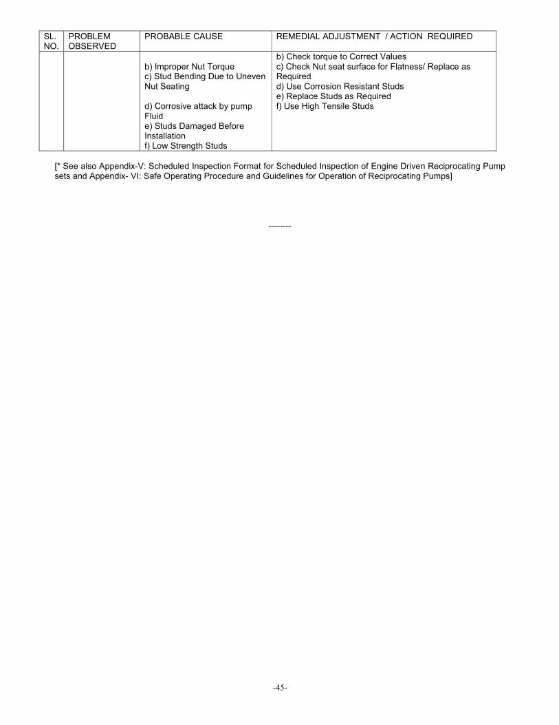
b) Improper Nut Torque c) Stud Bending Due to Uneven Nut Seating d) Corrosive attack by pump Fluid e) Studs Damaged Before Installation f) Low Strength Studs
b) Check torque to Correct Values c) Check Nut seat surface for Flatness/ Replace as Required d) Use Corrosion Resistant Studs e) Replace Studs as Required f) Use High Tensile Studs
[* See also Appendix-V: Scheduled Inspection Format for Scheduled Inspection of Engine Driven Reciprocating Pump sets and Appendix- VI: Safe Operating Procedure and Guidelines for Operation of Reciprocating Pumps]
--------
-46-
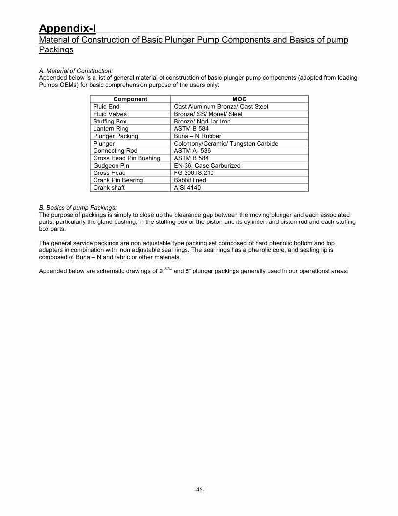
Appendix-I________________________________________________________________________ Material of Construction of Basic Plunger Pump Components and Basics of pump Packings
A. Material of Construction: Appended below is a list of general material of construction of basic plunger pump components (adopted from leading Pumps OEMs) for basic comprehension purpose of the users only:
Component MOC
Fluid End Cast Aluminum Bronze/ Cast Steel
Fluid Valves Bronze/ SS/ Monel/ Steel
Stuffing Box Bronze/ Nodular Iron
Lantern Ring ASTM B 584
Plunger Packing Buna – N Rubber
Plunger Colomony/Ceramic/ Tungsten Carbide
Connecting Rod ASTM A- 536
Cross Head Pin Bushing ASTM B 584
Gudgeon Pin EN-36, Case Carburized
Cross Head FG 300.IS:210
Crank Pin Bearing Babbit lined
Crank shaft AISI 4140
B. Basics of pump Packings: The purpose of packings is simply to close up the clearance gap between the moving plunger and each associated parts, particularly the gland bushing, in the stuffing box or the piston and its cylinder, and piston rod and each stuffing box parts. The general service packings are non adjustable type packing set composed of hard phenolic bottom and top adapters in combination with non adjustable seal rings. The seal rings has a phenolic core, and sealing lip is composed of Buna – N and fabric or other materials. Appended below are schematic drawings of 2
3/8” and 5” plunger packings generally used in our operational areas:

-47-

-48-
--------

-49-
Appendix-II____________________________________________________________________ Sample Technical Specification for Procurement of Gas Engine Driven Reciprocating Pump sets
Sample Technical Specifications for: GAS ENGINE DRIVEN CRUDE OIL DESPATCH PUMPSETS: A. PUMP: 1. Type Horizontal, single acting, triplex plunger pump as per API Standard 674 . 2. Capacity and Discharge The plunger size selected should be adequate to meet the pressure and volume requirements of 70 Kg/ Sq.cm and 60 CuM/hr respectively. 3. Pump Speed The speed limit of the offered pump shall be governed by the maximum allowable speed ratings for single acting plunger type pumps in continuous service as per API 674 standards . NOTE : ”Continuous duty” means pump having service operation on full load for a period of 8 hours to 24 hours per day as per Hydraulic Institute Standard application . 4. Fliud end features i. Aluminum Bronze / Forged Carbon Steel / Cast Nodular Iron , Valve over Valve , Mono Block Fluid End with bolt on type valve covers ii. Al Bronze / Carbon Steel / Nodular Iron stuffing boxes iii. Hard coated plungers iv. General service packing v. Suitably designed valves with tapered valve seats pressed onto mono block fluid end vi. Three feed belt driven packing lubricator, to drip feed (Make: PREMIER / MEGA) vii. Suction and Discharge on either side 5. Power end features i. One piece Cast Iron frame ii. Alloy steel / Cast Nodular Iron crankshaft iii. Heavy duty Taper Roller crankshaft bearings iv. Two piece, steel backed, precision type, Aluminum alloy / Tin & Babbit lined crank pin bearings v. Ductile / nodular iron connecting rods vi. Nodular Iron / Cast Iron cross heads vii. Bronze crosshead pin bushings viii. Alloy Steel crosshead pins ix. Stainless Steel pony / extension rods x. Flooded sump Splash Lubrication for power end xi. Sight glass gauge or oil level dipstick 6. Accessories i. Full flow, suitably sized and rated, spring loaded, Reset Relief Valve, mounted on the discharge piping. ( Make: OTECO/ BAIRD / CAMERON ) N.B: The relief valve is to be set at 110% of our maximum pressure requirement at the time of delivery. ii. Liquid filled discharge pressure gauge having a range up to 100 Kg/ Sq.cm , with built in dampening mechanism to minimize fluctuations for accurate response to pressure changes. ( Make : OTECO/ CAMERON / MARTIN DECKER ) iii. Suitably designed Suction Stabilizer and Discharge Pulsation Dampner , mounted and installed in line with the suction and discharge piping. N.B: Dampeners should be of Carbon Steel construction built to ASME pressure vessel codes and code stamped. iv. The pump suction piping should incorporate a suitably sized Gate / Ball valve while the discharge line should incorporate a suitably sized Ball valve , a Check valve and a Drain valve ( to de-pressurize the system when carrying out maintenance of the unit ) v. Complete set of fittings , interconnection piping and companion flanges with appropriate bolting , gaskets, dampener brackets, , blind flanges etc required for mounting all items mentioned above . vi. A Centrifugal Charge Pump , direct driven by a flameproof Electrical Motor , suitably sized to provide 1.5 times the input flow volume requirement of the triplex plunger pump should be provided against each pumping unit. The basic requirements of the Charge Pump system shall be as follows :

-50-
Pump : a. Horizontal Non Clogging Single Stage Centrifugal Pump b. Back Pull Out Design c. Thick Walled , Non Split Concentric Casing with Axial Suction and Tangential Discharge d. Semi Open , Single Shrouded , Curved Vane Impeller e. Strong Shaft with minimum overhang and Ceramic Coated Steel Shaft protection sleeve f. Gland Type Stuffing Box # lubrication & cooling of Gland internally by oil and grease g. Heavy duty and high efficiency design h. Heavy duty duplex set of angular contact bearing ( outboard ) and double row ball bearing ( inboard ) i. Suitably sized impeller to achieve desired head and discharge Motor : The electric motor should be 415 volts, 3 phase, 50 Hz, IP 55 explosion proof ( flame proof ) design suitable for electrical code for Group II A & II B , Zone 1 hazardous location as per IS 2148 , IS 9570 : 1980 and IS 5572 ( part 1 ) : 1978 or equivalent. The terminal box should be complete with explosion proof double compression type gland . N.B. :
• The motor should be certified by CMRI and approved by DGMS for deployment in the hazardous location mentioned.
• DGMS Logo should be embossed / fixed on the motor body 7. Duty / Service The pump should be designed for continuous duty application. Necessary credentials in this regard, in the form of product catalogues / brochures from OEM should be furnished. NOTE : “Continuous duty” means pump having service operation on full load for a period of 8 hours to 24 hours per day as per Hydraulic Institute Standard application. 8.Liquid to be handled : The pumping unit should be suitable for pumping crude oil . Recent Test reports of a typical sample is provided to assist the selection process : API Gravity at 60 Deg F : 30 PH : 7.2 Salinity ( ppm ) : 4400 CO3 : NIL HCO3 : 305 Pour Point ( Deg C ) : 27 Water Content ( % v / v ) : 21 Pumping Temp : 34 to 35 Deg C Viscosity : 13 cp @ 26 Deg C, 17 cp @ 24 Deg C, 29 cp @ 22 Deg C Sp Gravity : 0.8574 @ 35 Deg C and 0.8718 @ 15 Deg C 9. Suction condition :
Positive suction 10. Name plate and rotation arrows
A nameplate shall be securely attached at a readily visible location wherein the manufacturers name, machine serial number, maximum and minimum design limits and rating data, maximum allowable working pressure and temperatures, hydrostatic test pressure etc. should be clearly indicated. Rotation arrows indicating direction of rotation of major items should be cast in or attached. 11. Certificates and Documents to be forwarded I. The following documents should be forwarded along with the quotations: i. Product line catalogue, specifying materials of construction and constructional features of the triplex plunger pump and technical literatures of all ancillary equipment. ii. Performance chart of the plunger pump including all technical calculations such as hydraulic horse power, volumetric efficiency, mechanical efficiency, RPM, gear ratio, maximum plunger load, NPSH requirement, etc. II. The following documents shall have to be forwarded within a month of issue of LOI or placement of firm order i. A foundation diagram for the complete pump set indicating the static and dynamic loads of the package. III. The following documents must be forwarded along with the supply of equipment i. certified test results ii. certificate of hydrostatic testing iii. manufacturers certificate of authenticity

-51-
iv. certificate of test / conformance of pump and associated ancillaries like relief valves, pressure gauges, dampeners, etc. v. operation and maintenance manuals , parts lists of pump, engine , gear box and all other accessory equipment. B. SPEED REDUCTION GEAR BOX :
The speed reduction from the gas engine at its rated rpm to the desired rpm of the multistage centrifugal pump shall be effected by means of a separate external foot mounted gear box installed between the prime mover and the pump.
The Gear Box should be SHANTI/GREAVES Make parallel shaft speed reducer with a gear rated to designed HP from an engine at 1500 rated RPM to the pump at desired RPM, with a suitable Gear ratio, and a minimum 1.75 AGMA SF. The unit design includes cast iron housing, helical gear elements, anti-friction roller bearings on all shafts, and a self-contained splash lubrication system with a shaft driven lube oil pump and radiator type air/oil cooler to meet the thermal horsepower requirements.
Unit additionally includes thermostatic bypass valve and radiator type cooler. 1. Drive Coupling:
1(One) No. Falk high-speed Steel flex coupling size 1090-T10, complete with non sparking two piece shroud, to be utilized from the shaft of the engine PTO to the end of the bolt on pump gear reducer shaft. Coupling will be fitted utilizing a laser mounting system. Service factor of 2.0 2. Shaft extension: Spicer 1810 Drivelines coupled with slip yoke assemblies. This driveline set up should allow for the elimination of a center support bearing, and allow of angular deflection in the transmission line. This should also eliminate the need and task of attempting to align equipment blindly through constructed wall, and makes the center support bearing an optional item.
3. Others : 1(One) No. Driveline tubing, length = 48 Inch (1219. mm) long, 5.0 Inch Diameter. 2(Two) Nos Tube Yoke, for fit to end of PTO and input shaft of gear reducer. 1(One) No. Slip Yoke Assemblies. Listed allowable deflection is given as 30 Deg. Degree of actual deflection will be less than published. 2(Two) Nos U-Joints, 1810 Series
C. PRIME MOVER :
The prime mover should be a four stroke , water cooled gas engine rated for continuous power having a minimum net available HP of 189 HP with a limiting rpm of 1500 rpm and limiting compression ratio of 10.5 : 1 . The engine should comprise of the following sub systems : a) Cooling System The cooling system of water cooled engine should comprise of an engine mounted water pump, an industrial type heavy duty radiator/ heat exchanger suitable for operation in ambient temperature of 48 Deg C and a blower fan. (i) The engine jacket water cooling system should be a closed circuit design with provision for filling, expansion, and de-aeration. The cooling pump should be driven by the engine. Auxiliary coolant pump required for heat exchanger or separate circuit after cooling should also be engine driven. Coolant temperature should be internally regulated to disconnect external cooling system until operating temperature is achieved. (ii) Radiator, Engine Mounted: Heat rejected to the engine jacket water shall be discharged to the atmosphere through a close coupled radiator. The radiator shall be sized to cool the engine continuously while operating at full rated load and at site conditions of 48 Deg C ambient. (iv) Blower Fan: The radiator cooling fan shall be a blower type driven from the engine. Air shall be drawn from the engine side and exhausted through the radiator core with no more than 12.7 mm( 0.5 Inch ) of water external restriction in addition to core restrictions. (v) Fan and Belt guarding: The fan, fan drive, and fan belts shall be covered with punched steel mesh guarding for personnel protection. b) Air Intake System The air intake system should comprise of a heavy duty engine air cleaner mounted on the engine with a vacuum indicator and air intake manifold with dry element requiring replacement no more frequently than 500 hours or once each year. c) Electric Starting System: The engine should have an electric starting system comprising of a Maintenance Free Heavy Duty Battery pack of reputed make having a minimum capacity 180 ampere hours with a alternator mounted on the engine for a battery charging and a 24 Volt starter (preferably of LUCAS TVS/DELCO REMY make), starter relay, and automatic reset circuit breaker to protect against butt engagement. Batteries shall be maintenance free, lead acid type mounted near the alternator. Batteries should be housed in a hard rubber or polypropylene case with provision for venting. Required cables should be furnished and sized to satisfy circuit requirements. d) Battery Charger:

-52-
The battery charger is to be a solid-state device with adjustable float voltage control. It is to be a constant voltage device with current limit, and it is to include an equalize switch which will allow the battery to be overcharged for maintenance purpose. e) Ignition System : The ignition system should be a shielded ignition comprising Altronic III/V Engine driven ignition timer, Ignition Coil, High Tension and Low Tension Wiring Harness, Transformer and Spark Plugs shall incorporate gold palladium electrodes for reliability and life ( Preferably STITT/ CHAMPION make) f) Exhaust System : (i)The exhaust system should comprise of water cooled exhaust manifold, stainless steel exhaust flexible connection, residential type exhaust silencer, spark arrestor and piping connections (ii) Heavy walled piping of schedule 40 with radii of 90 Deg bend at least 1½ times the pipe diameter. Piping should be installed with appropriate insulation and shielding. (iii) Piping should be supported and braced to prevent weight or thermal growth being transferred to the engine and flexible expansion fittings provided to accommodate thermal growth. g) Fuel System : The fuel system should comprise of *governor(Preferably WOODWARD make), carburetor ( preferably IMPCO make ), main line and secondary line gas pressure regulator ( Preferably VANAZ/FISHER make ) , gas filter and related linkages. The first stage regulator is to have an inlet pressure rating of 20 psig and Outlet pressure rating of 7 Psig. * Governor, Electronic Speed Control: The engine governor shall be a Woodward Electronic Speed Control with EG Electro-Hydraulic actuator or Barber Coleman Equal .Speed drop shall be extremely adjustable from 0 ( isochronous) to 10% from no load to full rated load. Steady state frequency regulation shall be + / - 0.5 percent. Fuel inlet line to the engine shall be having stainless steel flexible connection to take care of vibration/shock if any, in the system. h) Lubricating System : The lubricating system should comprise of lubricating oil pump, lubricating oil filter with a replaceable paper element, lubricating oil cooler, lubricating oil pan and crankcase breather. (i) The lubricating oil pump shall be a positive displacement type that is integral with the engine and gear driven from the engine gear train. The system shall incorporate full flow filtration with bypass valve to continue lubrication in the event of filter clogging. (ii) The bypass valve must be integral with the engine filter base of receptacle. i) Instrument Panel : The engine mounted instrument panel shall consist of a shock-mounted formed and welded enclosure. Provide Metric marked gauges as above. The instrument panel should include the following : a) Lubricating Oil pressure gauge b) Lubricating oil temperature gauge c) Water temperature gauge d) Starting Switch e) Ignition Switch f) Mechanical/Digital tachometer and hour meter g) Circuit Breaker h) Ampere meter i) Electric service meter j) Engine Safety Controls : Engine mounted safety shut off/trip system for tripping the engine in the event of a) Low lubricating oil Pressure b) High cooling water temperature c) Engine over speed d) Over crank k) Other Features : a) flexible coupling / direct coupling b) AVM Pad. c) flywheel with housing d) lifting eyes e) coupling guard if applicable f) guards over belt drives ( blower fan, water pump drive pulley, timing

-53-
pulley) g) standard painting h) suitable hand throttle control i) mechanical hour meter j) SAE standard rotation. k) Gas shut off valve for engine fuel gas line should close automatically when the engine is stopped. N.B: Provision of guards over belt drives and couplings has become mandatory as per recommendation of OISD ( Oil Industry Safety Director) & DGMS ( Director General of Mines & Safety ) GENERAL NOTES ON ENGINE :
a) The engine shall conform to ISO : 3046 specifications and shall be rated for continuous power with an over load power rating of 110% of the continuous power corresponding to engine application for a period of 1 hr within a period of 12 hrs operation. b) The engine governing should be in accordance with Class A Governing specified in BS : 3109 : 1985 ( or latest) c) The bidder should submit the following information along with relevant performance rating Curves and engine product catalogue: i) Gross HP developed at rated RPM ii) Deduction for fan and other ancillary equipment. iii) Net HP developed at rated RPM iv) Specific fuel consumption at rated power as well as at 110%, 75%, 50% and 25% of rated load d) A suitable selected flexible coupling should be incorporated to transfer power from the engine to the alternator. A guard should be provided to cover the same to meet OISD norms e) The generating set should be suitable for operation at the following site condition : Maximum Temperature : 48 DEG C Minimum Temperature : 05 DEG C Maximum Humidity at 21 DEG C : 100 % at 35 DEG C : 95 % at 41 DEG C : 70 % Maximum Altitude above sea level : 150 mt f) Composition of Fuel Gas : The engine should be capable of developing required BHP as detailed in para 2.0 above with fuel composition given below- CONSTITUTION % VOLUME Methane 89.442 Ethane 4.267 Propane 2.083 Butane- Pentane 6 - 3 Nitrogen 94.5 Carbon-dioxide 0.434 Iso-Butane 0.641 N-Butane 0.892 Iso-Pentane 0.353 N-Pentane 0.271 Hexane 0.672 Gravity 0.655 Gross Calorific Value 1300- 1100 BTU/CFT Net Calorific Value 1200- 1045 BTU/CFT g) The fuel gas system shall consists of a minimum of following components but shall not be limited to these : a) Main line pressure regulator. b) Pressure relief safety valve. c) Gas scrubber tank. d) Gas fuel filter. e) Interconnecting gas piping from main line pressure regulator to engine. f) The gas conditioning & piping should be carried out in such a way as to prevent condensate carry over to engine .

-54-
h) The bidder must undertake and confirm from OEM’s that the equipment to be supplied are not going to become obsolete for the next 10 years and provisioning of spares can be continued. D. INSTRUMENTATION FOR CODP:
1. The CODP shall be controlled by a Programmable Logic Controller (PLC) with Panel view facility for display & alarm of critical parameters and safety shutdown.
2. The PLC shall be Rockwell Automation make SLC 5/03 processor with necessary I/O (Input/Output) modules. It shall also be provided with an Ethernet communication module for remote monitoring of the CODP parameters from control room.
3. The PLC shall be housed in an explosion proof control panel with a glass window for viewing the CODP parameters. The Control panel shall be certified to use in Zone1, Zone2, Gas group IIA & IIB (Division 1, Division 2, Gas group Class I, Group C&D) environment.
4. The Control panel shall be designed for installation in the Engine side (behind the Fire Wall) of the CODP. 5. The following minimum instruments shall be provided for CODP:
• Pump Suction Pressure Transmitter
• Pump Discharge Pressure Transmitter
• Pump Vibration Switch
• Oil level switch for Pump sump
• Oil level switch for Gear Box
• Oil Level switch for Engine sump
• Engine Oil Pressure Transmitter
• Engine Water Temperature Transmitter
• Engine Speed Transmitter
• Pump Outlet Flow Transmitter 6. All the Instruments shall be certified for use in Zone1, Zone2, Gas group IIA & IIB (Division 1, Division 2,
Gas group Class I, Group C&D) environment. 7. All the Electronic instruments placed on the Pump side should be approved by DGMS (Director General of
Mines Safety), Dhanbad. 8. The possibility of bringing the Pump suction and Pump Discharge Pressure Transmitters to the Engine
side (behind the fire wall) by using remote diaphragm seal shall be looked into by the supplier. 9. The supplier has to provide 3 (THREE) sets each of the following documentation:
• Operation and maintenance manual of each field Instrument
• Instrument list and Instrument data sheets
• Test & Calibration reports
• As built & Hook up drawings
• Wiring diagram of the control panel
• Detailed operation and maintenance manuals of the PLC system
• Ladder logic developed for the PLC 10. The supplier has to provide ONE Lap-top computer for Programming the PLC. It shall be loaded with the
relevant Allen-Bradley software like RS LOGIX, RS LINX and PANEL VIEW. 11. The Technical Specification of the Instruments for CODP is as given below: Technical specification for Instruments 1. PUMP SUCTION PRESSURE TRANSMITTER
MAKE : DRUCK or Equivalent MODEL : PTX1240 RANGE : 0 TO 200 PSI OUTPUT : 4 TO 20mA
2. PUMP DISCHARGE PRESSURE TRANSMITTER
MAKE : DRUCK or Equivalent MODEL : PTX1240 RANGE : 0 TO 3000 PSI OUTPUT : 4 TO 20mA
3. PUMP VIBRATION SWITCH
MAKE : MURPHY or Equivalent MODEL : VS2EX To detect vibration / Shock in 3 places of motion Fully adjustable Manual / Electrical reset
4. OIL LEVEL SWITCH (PUMP SUMP, GEAR BOX, ENGINE)
MAKE : MURPHY or Equivalent MODEL : EL150X Float : Brass

-55-
Contact rating : 2A, 30 VDC Max Working Pressure: 25 PSI
5. ENGINE OIL PRESSURE TRANSMITTER
MAKE : DRUCK or Equivalent MODEL : PTX1240 RANGE : 0 TO 200 PSI OUTPUT : 4 TO 20mA
6. ENGINE WATER TEMPERATURE TRANSMITTER
MAKE : MATE or Equivalent MODEL : 4100 RANGE : 0 TO 300 DEG F
7. ENGINE SPEED TRANSMITTER
MAKE : ELECTRONIC DATA DEVICES or Equivalent MODEL : FTC 4.02420 RANGE : 0 TO 2000 RPM OUTPUT : 4 TO 20mA
8. TURBINE FLOWMETER
MAKE : NU FLO or Equivalent MODEL : MC II PLUS EXP POWER SUPPLY: MAX 30 VDC OUTPUT : 4 TO 20 mA LCD DISPLAY: FLOW RATE & TOTAL FLOW
NOTE: 1. In case, the control panel is placed on engine side, which is a safe area and there is a fire wall between the pump and engine, flame proof/purged control panel is not required. 2. The instruments which are directly mounted on the pump and pipe line such as vibration switches, level switches, pressure switches, turbine flow meter, pressure transmitters etc should have certification for use in Class 1, Division 2, Group C & D gases hazardous area.
E : CONTROL PANEL:
One PLC based Nema 7R enclosure pump system control panel with the following descriptive features.
Engine driven control panel as per the following:
• Nema 7, enclosure suitable for class I, div. I, groups C/D area.
• Allen Bradley SLC-500 modular plc system
• Allen Bradley Panelview 300 micro operators interface mounted behind a 5" glass viewing window.
All normal operational functions should be available using door mounted push buttons. Set points can be adjusted using the Panel view function keys.
Digital readout with shutdown and alarm annunciation for the following: 1. Pump discharge pressure 2. Pump suction pressure 3. Engine oil pressure 4. Engine water temperature 5. Engine speed (rpm) 6. analog spares
The following discrete alarms/shutdowns should also be provided:
1. Pump crank case oil level 2. Gear reducer oil level 3. Pump vibration 4. Engine radiator jacket water level 1/2 5. Engine low oil level 6. Emergency shutdown push button
24 VDC control power supply shall be provided for the following devices: 1. Pump discharge pressure transducer 2. Pump suction pressure transducer 3. Engine oil pressure transducer 4. Engine water temperature transducer

-56-
5. Engine rpm transducer N.B.: A fuel gas solenoid valve should additionally be incorporated in the fuel gas line of the engine to cut off the fuel supply and protect the engine in the event of an engine over speed situation.
F. DRIVE ARRANGEMENT : The drive arrangement will involve flow of prime mover power through a flywheel mounted clutch PTO to the input shaft of an external foot mounted gearbox and finally to the crankshaft of the triplex pump. An extension shaft supported by pedestal bearings should be incorporated between the output shaft of the clutch PTO and the input shaft of the external foot mounted gear box to facilitate construction of a fire brick wall for adherence of safety norms associated with deployment of such equipment within hazardous areas . The length of the extension shaft as well as it#s diameter and material should be suitably designed to match the power torque requirements of the transmission. Suitably selected Flexible Disc / Grid Member Couplings should be incorporated to transfer power from the prime mover to the triplex pump through the transmission , as illustrated in the schematic diagram.
G. PUMP PACKAGE UNITIZATION:
The pump set is to be supplied with all components and accessories fitted and mounted on an oilfield type three runner portable master skid. The floor of the skid should be covered with anti skid steel plates. While unitizing the pump set, easy approach to various components should be kept in mind, to facilitate operational and maintenance requirements. The skid should be fabricated out of properly sizes beams to withstand loading / unloading and transfer in oil field trucks. The skid shall be sized to contain the entire pump and engine unit and should include the following components: a) Drip pan for cradle/fluid area of pump and packing area complete with threaded drain b) Dip lip for cradle / fluid area of pump and packing area c) Grouting holes d) Radiator bumper guard e) Exhaust tubing and supports f) Gas volume tank g) Horizontal adjustment screws for minor adjustment h) Charge pump bypass system and valving i) Two grouting bosses on skid j) Interconnection piping spool pieces on suction and discharge with ancillary components k) Non sparking Aluminum safety guards.
N.B.: a) The unitization process shall include supply and fitting of miscellaneous electrical instrumentation
including: i) Engine oil level switch ii) Pump oil level switch iii) Vibration switch mounted on pump and engine iv) Gas volume Regulator v) Termination of all skid mounted end devices to the control panel

-57-
b) Paint / finish specifications shall consist of wire brushing structural pieces and piping, solvent cleaning of components, one coat of red oxide alkyd primer 2.0 to 2.5 mils dry film thickness. The top coat shall be one coat of gloss sakyd national blue enamel 1.0 to 2.0 mils dry film thickness.
c) ASME Coded 30 gallon Gas volume Tank complete with pressure gauges, inlet & outlet ball valves, drain
valve and pressure regulator (50 to 70 psi inlet/20 psi outlet). Fuel line plumbed to engine gas fuel inlet 1 X 6 ½” W/S 201 2” regulator.
H. INSPECTION AND TESTING : The pump set shall be inspected by OIL’s deputed engineer at manufacturers / assemblers works / factory prior to dispatch. However, such inspection will not relieve the supplier of his responsibility to ensure that the equipment supplied conforms to the correct specifications and is free from manufacturing and all other defects. The supplier shall carry out full load performance test on the pump set , at duty conditions , in the presence of OIL’s deputed representative . N.B. : Charges for carrying out the above tests at the manufacturer’s facility should be included in the purview of the offer. I. COMMISSIONING : The pump sets shall have to be commissioned at site by competent personnel deputed by the bidder for the same. OIL shall provide necessary local transportation , within its operational area, for the commissioning personnel, to and from site. J. WARRANTY : The warranty period for the engine, pump set and all ancillary equipment should be a minimum of 18 months from the date of dispatch / shipment or 12 months from the date of commissioning. K. SPARE PARTS AND SPECIAL TOOLS : a. Bidders have to provide the price , along with the part numbers , of the following spares that we envisage shall be required for maintenance of the pump set for two years . The prices of these spares shall be considered during commercial evaluation of the offer. TRIPLEX PLUNGER PUMP : i. SUCTION VALVE ASSEMBLY : 3 NOS PER PUMP ii. DELIVERY VALVE ASSEMBLY : 3 NOS PER PUMP iii. VALVE COVER GASKET : 12 NOS PER PUMP iv. VALVE SEAT ( SUCTION ) : 3 NOS PER PUMP v. VALVE SEAT ( DELIVERY) : 3 NOS PER PUMP vi. ROD WIPER : 6 SETS PER PUMP vii. PLUNGER : 3 NOS PER PUMP viii. PLUNGER PACKING : 6 SETS PER PUMP ( EACH SET ADEQUATE TO CATER FOR 3 PLUNGERS) ix. CRANK PIN BEARING : 3 SETS PER PUMP GAS ENGINE : i. SPARK PLUG : I SET PER ENGINE ii. IGNITION TRANSFORMER : 1 SET PER ENGINE iii. LUB OIL FILTER ELEMENT : 6 NOS PER ENGINE iv. SET OF VEE BELTS : 2 SETS PER ENGINE v. AIR FILTER ELEMENT : 4 NOS PER ENGINE vi. SET OF GASKETS : 1 SET PER ENGINE b. Bidders shall have to provide the unit price , along with the part numbers , of the following insurance spares . The cost of these spares shall however not be considered during commercial evaluation of the offer. TRIPLEX PLUNGER PUMP :
i. FLUID END ii. STUFFING BOX ASSEMBLY iii. GLAND NUT iv. EXTENSION ROD v. CRANKSHAFT vi. CROSS HEAD vii. CONNECTING ROD ASSEMBLY GAS ENGINE : i. CYLINDER HEAD INCLUDING HEAD GASKET ii. CYLINDER LINER iii. PISTON ASSEMBLY INCLUDING PISTON RINGS
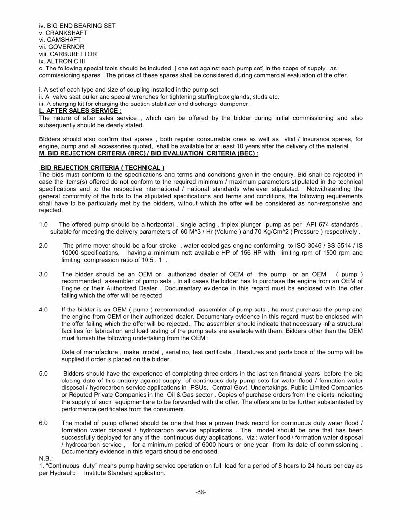
-58-
iv. BIG END BEARING SET v. CRANKSHAFT vi. CAMSHAFT vii. GOVERNOR viii. CARBURETTOR ix. ALTRONIC III c. The following special tools should be included [ one set against each pump set] in the scope of supply , as commissioning spares . The prices of these spares shall be considered during commercial evaluation of the offer. i. A set of each type and size of coupling installed in the pump set ii. A valve seat puller and special wrenches for tightening stuffing box glands, studs etc. iii. A charging kit for charging the suction stabilizer and discharge dampener. L. AFTER SALES SERVICE : The nature of after sales service , which can be offered by the bidder during initial commissioning and also subsequently should be clearly stated. Bidders should also confirm that spares , both regular consumable ones as well as vital / insurance spares, for engine, pump and all accessories quoted, shall be available for at least 10 years after the delivery of the material. M. BID REJECTION CRITERIA (BRC) / BID EVALUATION CRITERIA (BEC) : BID REJECTION CRITERIA ( TECHNICAL ) The bids must conform to the specifications and terms and conditions given in the enquiry. Bid shall be rejected in case the items(s) offered do not conform to the required minimum / maximum parameters stipulated in the technical specifications and to the respective international / national standards wherever stipulated. Notwithstanding the general conformity of the bids to the stipulated specifications and terms and conditions, the following requirements shall have to be particularly met by the bidders, without which the offer will be considered as non-responsive and rejected. 1.0 The offered pump should be a horizontal , single acting , triplex plunger pump as per API 674 standards ,
suitable for meeting the delivery parameters of 60 M^3 / Hr (Volume ) and 70 Kg/Cm^2 ( Pressure ) respectively . 2.0 The prime mover should be a four stroke , water cooled gas engine conforming to ISO 3046 / BS 5514 / IS
10000 specifications, having a minimum nett available HP of 156 HP with limiting rpm of 1500 rpm and limiting compression ratio of 10.5 : 1 .
3.0 The bidder should be an OEM or authorized dealer of OEM of the pump or an OEM ( pump )
recommended assembler of pump sets . In all cases the bidder has to purchase the engine from an OEM of Engine or their Authorized Dealer . Documentary evidence in this regard must be enclosed with the offer failing which the offer will be rejected
4.0 If the bidder is an OEM ( pump ) recommended assembler of pump sets , he must purchase the pump and
the engine from OEM or their authorized dealer. Documentary evidence in this regard must be enclosed with the offer failing which the offer will be rejected.. The assembler should indicate that necessary infra structural facilities for fabrication and load testing of the pump sets are available with them. Bidders other than the OEM must furnish the following undertaking from the OEM :
Date of manufacture , make, model , serial no, test certificate , literatures and parts book of the pump will be supplied if order is placed on the bidder.
5.0 Bidders should have the experience of completing three orders in the last ten financial years before the bid
closing date of this enquiry against supply of continuous duty pump sets for water flood / formation water disposal / hydrocarbon service applications in PSUs, Central Govt. Undertakings, Public Limited Companies or Reputed Private Companies in the Oil & Gas sector . Copies of purchase orders from the clients indicating the supply of such equipment are to be forwarded with the offer. The offers are to be further substantiated by performance certificates from the consumers.
6.0 The model of pump offered should be one that has a proven track record for continuous duty water flood /
formation water disposal / hydrocarbon service applications . The model should be one that has been successfully deployed for any of the continuous duty applications, viz : water flood / formation water disposal / hydrocarbon service , for a minimum period of 6000 hours or one year from its date of commissioning . Documentary evidence in this regard should be enclosed.
N.B.: 1. “Continuous duty” means pump having service operation on full load for a period of 8 hours to 24 hours per day as per Hydraulic Institute Standard application.

-59-
2. Hydrocarbon Service Application of continuous duty plunger pumps in the context of our NIT refers to applications where such pumps are deployed for duties such as crude oil transfer, condensate injection , polymer injection , glycol injection etc in the E & P Sector and also continuous duty handling of petroleum and petrochemical products in the Refining & Distribution Sector of the Oil & Gas Industry. N. TECHNICAL CHECK LIST
1. Whether quoted as OEM of Pump and whether documentary evidences submitted ?
YES/NO
2. Whether quoted as authorised dealer of Pump and whether documentary evidences submitted ?
YES/NO
3. Whether quoted as OEM recommended assembler of Pump sets and whether documentary evidences submitted ?
YES/NO
4. Whether the offered Pump is a horizontal, triplex plunger Pump as per API 674 standard ?
YES/NO
5. Whether the Pump is designed for continuous service duty ? YES/NO
6. Whether the offered engine conforms to ISO3046 / BS 5514 / IS 10000 specifications ?
YES/NO
7. Whether the Minimum Net HP of the engine is as per NIT requirement ? YES/NO
8. Whether the engine is rated for continuous power ? YES/NO
9. Whether the engine is water cooled ? YES/NO
10. Whether Instrumentation for CODP & Technical Specification for Instruments is as per NIT requirement ?
YES/NO
11. Whether Electronic Instruments placed on the pump side is approved by DGMS ?
YES/NO
12. Whether the speed reduction gear box is external foot-mounted ? YES/NO
13. Whether the floor of the three runner skid shall be covered by checkered plates ?
YES/NO
14. Whether Flexible disc / grid member couplings have been incorporated in the transmission ?
YES/NO
15. Whether guards shall be provided over couplings and belt drives ? YES/NO
16. Whether the two years spares for the packages indicated have been quoted ? YES/NO
17. Whether special tools and commissioning spares have been included in the scope of supply ?
YES/NO
18. Whether spares shall be available for 10 years after supply of equipment? YES/NO
19. Whether separately highlighted any deviation from the technical specifications ? YES/NO
20. Whether the Pre-despatch inspection of the Pump packages shall include Full Load Performance test of the Pump Sets ?
YES/NO
Order Ref --------------------------------------------------------- Dated------------------------------- OIL’s Tender No.----------------------------------------------- Signed------------------------------- For & behalf of ------------------------------------------------- Designation------------------------ O. DATA SHEET DATA SHEET ( ENGINE )
MAKE
MODEL
NUMBER OF CYLINDERS
ASPIRATION
COMPRESSION RATIO
SIZE (BORE X STROKE )
DISPLACEMENT
RATED SPEED
DUTY
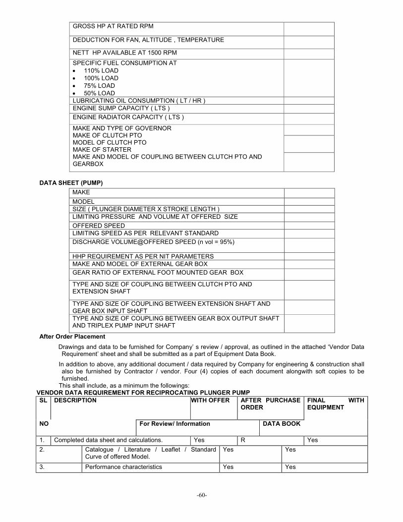
-60-
GROSS HP AT RATED RPM
DEDUCTION FOR FAN, ALTITUDE , TEMPERATURE
NETT HP AVAILABLE AT 1500 RPM
SPECIFIC FUEL CONSUMPTION AT
• 110% LOAD
• 100% LOAD
• 75% LOAD
• 50% LOAD
LUBRICATING OIL CONSUMPTION ( LT / HR )
ENGINE SUMP CAPACITY ( LTS )
ENGINE RADIATOR CAPACITY ( LTS )
MAKE AND TYPE OF GOVERNOR MAKE OF CLUTCH PTO MODEL OF CLUTCH PTO MAKE OF STARTER MAKE AND MODEL OF COUPLING BETWEEN CLUTCH PTO AND GEARBOX
DATA SHEET (PUMP)
MAKE
MODEL
SIZE ( PLUNGER DIAMETER X STROKE LENGTH )
LIMITING PRESSURE AND VOLUME AT OFFERED SIZE
OFFERED SPEED
LIMITING SPEED AS PER RELEVANT STANDARD
DISCHARGE VOLUME@OFFERED SPEED (n vol = 95%)
HHP REQUIREMENT AS PER NIT PARAMETERS
MAKE AND MODEL OF EXTERNAL GEAR BOX
GEAR RATIO OF EXTERNAL FOOT MOUNTED GEAR BOX
TYPE AND SIZE OF COUPLING BETWEEN CLUTCH PTO AND EXTENSION SHAFT
TYPE AND SIZE OF COUPLING BETWEEN EXTENSION SHAFT AND GEAR BOX INPUT SHAFT
TYPE AND SIZE OF COUPLING BETWEEN GEAR BOX OUTPUT SHAFT AND TRIPLEX PUMP INPUT SHAFT
After Order Placement
Drawings and data to be furnished for Company’ s review / approval, as outlined in the attached ‘Vendor Data Requirement’ sheet and shall be submitted as a part of Equipment Data Book.
In addition to above, any additional document / data required by Company for engineering & construction shall also be furnished by Contractor / vendor. Four (4) copies of each document alongwith soft copies to be furnished.
This shall include, as a minimum the followings: VENDOR DATA REQUIREMENT FOR RECIPROCATING PLUNGER PUMP
SL DESCRIPTION WITH OFFER AFTER PURCHASE ORDER
FINAL WITH EQUIPMENT
NO For Review/ Information DATA BOOK
1. Completed data sheet and calculations. Yes R Yes
2. Catalogue / Literature / Leaflet / Standard Curve of offered Model.
Yes Yes
3. Performance characteristics Yes Yes

-61-
4. GA drawing for pump, driver & accessories including dimensional outline.
Yes R Yes
5. Auxiliary system schematic diagram – cooling and lube oil ( as applicable )
Yes R Yes
6. Cross-sectional drawing with parts lists and material of construction.
Yes I Yes
7. Mechanical seal cross-sectional drawing. Yes I Yes
8. Mechanical seal flushing diagram including all accessories ( as applicable )
R Yes
9. Schematic & wiring diagram for electrical control and instrumentation.
R Yes
10. Coupling data & drawing. I Yes
11. Foundation Plan - Anchor bolt details. I Yes
12. Data for external forces & moments. I Yes
13. Torsional vibration and critical speed calculation.
I Yes
14. Driver requirement data. I Yes
15. Torque speed characteristics I Yes
16. Part list & Material of Construction. I Yes
17. Completed lube schedule I Yes
18. Proposed test procedure and erection details R Yes
19. Material Test Certificates. R* Yes
20. Performance Test Records including curves and data.
R* Yes
21. Installation, Operating & Maintenance manual. I Yes
22. Mechanical clearance diagram I Yes
23. Mechanical Catalogue containing all the final drawings.
I Yes
24. List of spare parts I Yes
25. List of tools I Yes
26. List of deviations from spec. Yes
27. Experience Details Yes
28. Maintenance schedule ( 2 sets ) – laminated
Yes
29. Vendor / Manufacturer Guarantee / Warranty
Yes
LEGEND: I - INFORMATION, R- REVIEW, * at the time of inspection.
All drawings, calculations and data sheets will require review and approval by Company and will require the issue of “as-built” documents by Contractor.
All drawings shall have the Purchaser equipment number and purchase order number.
Vendor shall provide a complete document package for unit components and specific for protection of the equipment if taken out of service for finite periods.
Shop details shall be completed with all dimensions, thickness and details of construction including all nozzle locations and orientations. All material thickness shall be shown. All welds shall be detailed for fully described by notes or weld symbols and annotated to the relevant weld procedure specification.
Review of the drawings by Company does not relieve Contractor of his responsibility for the correctness of the design to suit the stated conditions.
--------

-62-
Appendix-III _____________________________________________________________________ Details of Prominent OEMs
Equipment Manufacturer Contact Details of OEM Contact Details of Authorized Regional Agent
National Oilwell
www.natoil.com 7909 Parkwood Circle Drive Houston, Texas 77036-6565 Office: 713 346 7340 Fax: 713 346 7369
Indian Petroleum Services Pvt Ptd, 510, Tolstoy Marg, New Delhi-110001 [email protected]
Gardner Denver
Gardner Denver Compressor and Pump Division, 1800 Gardner Expressway, Quincy, Illinois 62301 Customer Service Department Telephone: (800) 682-9868 FAX: (217) 224-7814
Larsen & Toubro Limited, IED, North Block, 1st floor Powai(W), Gate No 1 Saki Vihar road Powai (W), Mumbai -400072 India PHONE: 011-91-222-858-1401 FAX: 91 222-8581927
Pump
BPCL Bharat Pumps and Compressors Ltd, Naini , Allahabad- 211010, India
Cummins Cummins India Ltd, 35 A/1/2, Erandwana, Pune-411 038
Saurabh Auto Pvt Ltd., Solapar, Paltan Bazar , Guwahati- 781 008 India
Prime Mover (Engine)
Caterpillar TIL Limited 1, Taratolla Road, Kolkata- 700 024
Ghatge Patil Ghatge Patil Industires Ltd., Uchgaon, Kolhapur-416 005, India Ph: 91-231-2608000 Fax no:91-231-2608080 Email: [email protected]
Clutch PTO
Twin Disc TWIN DISC, INCORPORATED - INDIA EL HEIGHTS, 1st Floor3 CMM Street Nungambakkam, Chennai , 600 034 IndiaPhone:91-44-28213099
Gear Box Greaves http://www.powertransmission.com http://www.premiumtransmission.com/ Unit I, Mumbai Pune Highway Chinchwad, Pune - 411 019 Maharashtra, India Phone: 0091 20 27472385/ 27488886 Fax: 0091 20 27450287/ 27476601 E-mail: [email protected] Contact: Rajan N Area Sales Executive Power Transmission Group Kolkata: Thapar House, 25
Global Udyog,40, Strand Road, 4th floor, R.No:21C Kolkata-700 001(WB), India Call: 91-33-2210 3910, fax: 91-33-2242 3059. Email: [email protected]
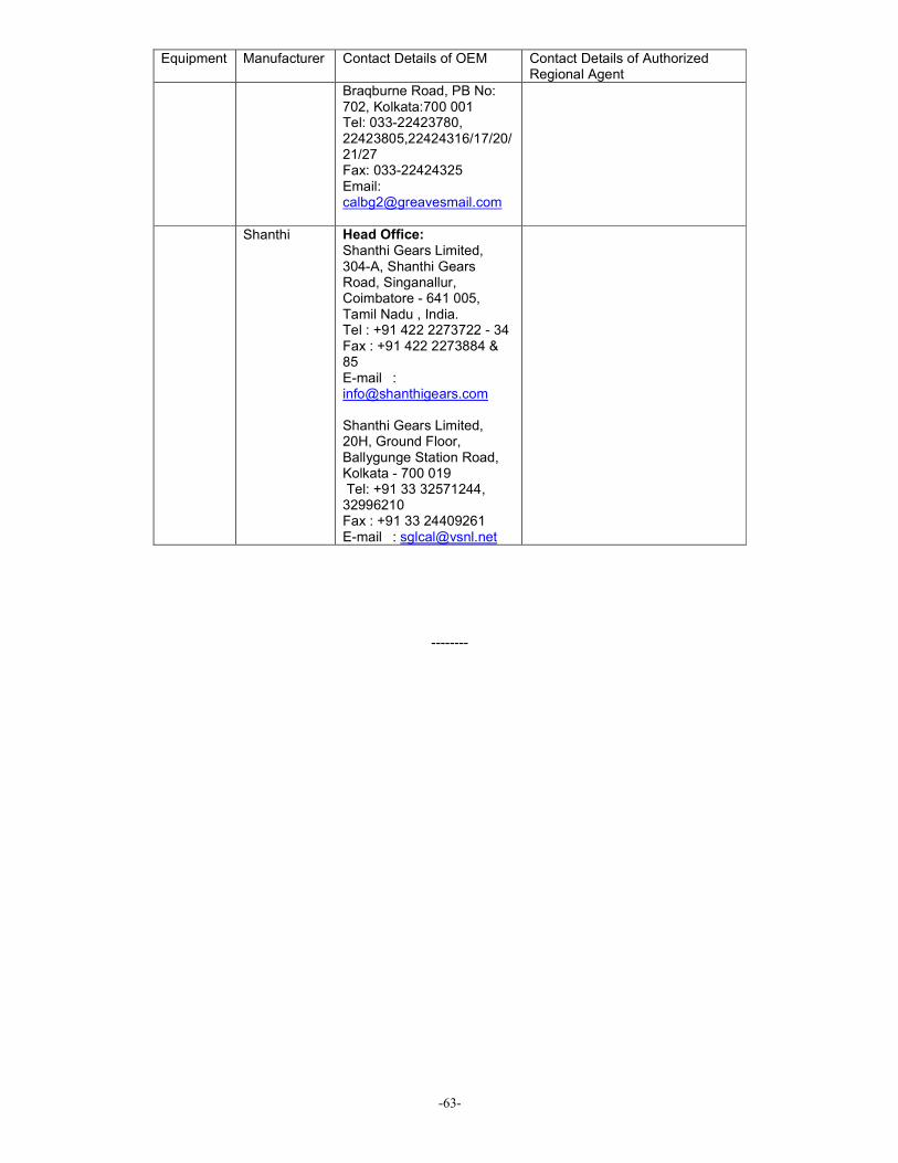
-63-
Equipment Manufacturer Contact Details of OEM Contact Details of Authorized Regional Agent
Braqburne Road, PB No: 702, Kolkata:700 001 Tel: 033-22423780, 22423805,22424316/17/20/21/27 Fax: 033-22424325 Email: [email protected]
Shanthi Head Office: Shanthi Gears Limited, 304-A, Shanthi Gears Road, Singanallur, Coimbatore - 641 005, Tamil Nadu , India. Tel : +91 422 2273722 - 34 Fax : +91 422 2273884 & 85 E-mail : [email protected] Shanthi Gears Limited, 20H, Ground Floor, Ballygunge Station Road, Kolkata - 700 019 Tel: +91 33 32571244, 32996210 Fax : +91 33 24409261 E-mail : [email protected]
--------

-64-
Appendix-IV _______________________________________________________________________ Basics of Reciprocating Pump Plunger Lubricators Description:
Lubricators will accurately deliver a predetermined quantity of oil normally under pressure, at regular intervals to moving parts on all types of industrial machinery. The lubricator consists of a reservoir, drive mechanism, and oil pumps. They are furnished in electric motor drive or shaft driven from the machinery to be lubricated. Shaft driven units can be direct drive, pulley/sheave, or oscillating drive motion. Lubricator Features/Specifications: • Force Feed Lubricators • Heavy Duty Steel Reservoirs • All Gear Rotary Drives • Electric Motor Drives • Ratchet Drives • Bottom Rotary Drives • Suitable for Use with Petroleum and Synthetic Lubricants • Automatically Oil Level Controllers • Low Level Switches • Electric Heat & Thermostat Assemblies • Shaft Rotation Alarms • Partitions in Reservoir for Two or More Different Lubricants • Check Valves available in Carbon Steel and Stainless Steel Pump Features/Specifications of Prominent Manufacturers:
• 3/16” Pumps to 7,500 PSI (.010 in3 per stroke max) • 1/4” Pumps to 8,000 PSI (.018 in3 per stroke max) • 3/8” Pumps to 3,500 PSI (.041 in3 per stroke max) • Box Suction Pumps (Vacuum Feed) • Pressurized Suction Pumps with Sight Feed • Pressurized Suction Pumps with Blind Sight Feed • One Piece Steel Pump Body • Modular Cast Iron Cylinder Assembly • Pyrex Sight Glass with Protective Housing • Suitable for Petroleum and Synthetic Lubricants • Hardened Steel Rocker Arm • Hardened Steel Roller Rocker Arm for High Pressure Applications • Weatherproof Construction • Furnished as original equipment by engine, pump and compressor manufacturers Operating Instructions: 1. Box Suction Pumps (Vacuum Feed) Type: • Fill reservoir with oil. • Loosen union nut on pump outlet • Remove the vent screw and fill the sight glass with oil. Replace vent screw and prime by manually pumping flushing unit until air free oil is observed from the drip tube, and oil level drops in the sight glass • Tighten union nut • Maintain oil level in sight glass below the drip tube so drops can be observed

-65-
Flow Rate Adjustment • Loosen locknut on flushing unit • Turn flushing unit counter-clockwise to increase flow • Turn flushing unit clockwise to decrease flow • Tighten locknut when desired flow rate is achieved Sight Glass • In a vacuum type sight feed, it is not uncommon for oil level in the sight glass to drop during operation. Absence of a level indicates air is being taken in with the oil and some oils, due to viscosity conditions, will release air faster than others. When the quantity of air becomes excessive, it can eventually air lock the pump. For this reason it is recommended an oil level in the sight glass be maintained. When level drops, remove the vent screw and fill sight glass to top; replace vent screw and operate flushing unit manually, observing that oil in the sight glass is free from air. If air is not expelled, it may be necessary to loosen union nut (on pump outlet) and expel air at this point. It is desirable to maintain level below the drip tube so drops can be seen during operation. Due to viscosity conditions, some oils release air faster than others. For this reason, it is difficult to indicate how long the sight glass level can be maintained before a diminishing oil level occurs. Overfilling of Sight Glass • In a vacuum type sightfeed, it is not uncommon to see a reverse action whereas sight glass fills with oil and the drops can not be observed. Overfilling is caused by oil absorbing air in the sight glass and normally does not affect the operation of the pump. Remove the vent screw from sight glass and allow level to drop below drip tube. Tighten vent screw and check to see that air free oil from drip tube can be observed in the sight glass. If overfilling continues, it may be caused by plunger wear and oil slippage is being drawn back to sight glass. If this is the problem, the feed setting in drops per stroke will then automatically be reduced by the amount of slippage. Reservoir Oil Level (Loss of Prime) • If reservoir runs low on oil (at a point below the suction inlet of the pump) it may be necessary to prime individual pumps after filling, using procedure listed above.
2. Pressurized Suction Pumps (Blind Sightfeed) • Install pump in lubricator reservoir. • Loosen union nut on pump outlet and fill pump with oil and prime by manually pumping flushing unit until air free oil is observed around union nut. It may be necessary to install a manual hand priming gun in the inlet of the pump to expel the air from pump. After this is accomplished tighten union nut. Flow Rate
• Loosen lock nut on flushing unit. • Turn the flushing unit counter clockwise to increase flow. • Turn flushing unit clockwise to decrease flow. • Tighten lock nut when desired flow rate is achieved. 3. Pressurized Suction Pumps w/ Sight Glass
• Install pump in lubricator reservoir. • Loosen union nut on pump outlet • Remove the vent screw and fill the sight glass with oil. Replace vent screw and prime by manually pumping flushing unit until air free oil is observed from the drip tube, and oil level drops in the sight glass • Tighten union nut • Maintain oil level in sight glass below the drip tube so drops can be observed Flow Rate
• Loosen lock nut on flushing unit. • Turn flushing unit counter clockwise to increase flow. • Turn flushing unit clockwise to decrease flow. • Tighten lock nut when desired flow rate is achieved.
--------
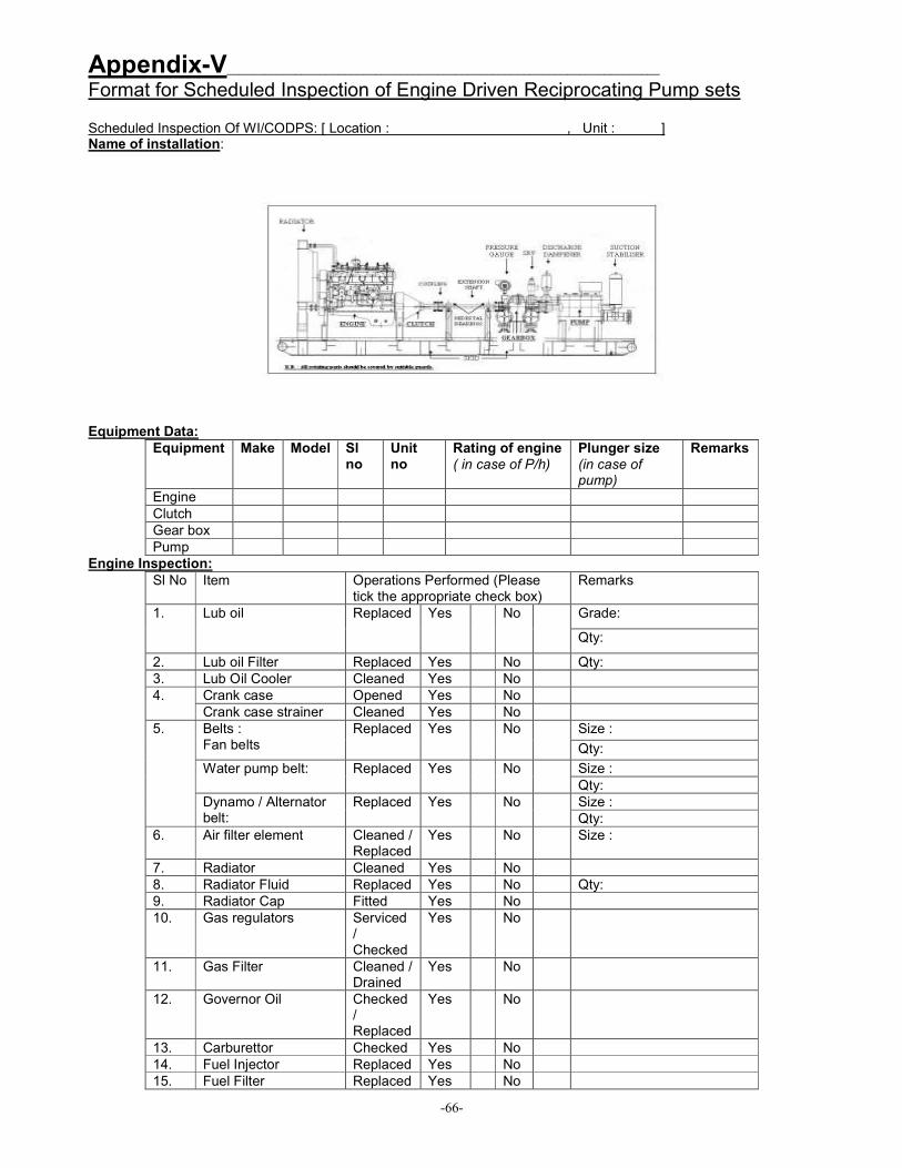
-66-
Appendix-V______________________________________________________________________
Format for Scheduled Inspection of Engine Driven Reciprocating Pump sets Scheduled Inspection Of WI/CODPS: [ Location : , Unit : ] Name of installation: Equipment Data:
Equipment Make Model Sl no
Unit no
Rating of engine
( in case of P/h)
Plunger size
(in case of pump)
Remarks
Engine
Clutch
Gear box
Pump
Engine Inspection:
Sl No Item Operations Performed (Please tick the appropriate check box)
Remarks
Grade: 1. Lub oil
Replaced Yes No
Qty:
2. Lub oil Filter Replaced Yes No Qty:
3. Lub Oil Cooler Cleaned Yes No
Crank case Opened Yes No 4.
Crank case strainer Cleaned Yes No
Size : Belts : Fan belts
Replaced Yes No
Qty:
Size : Water pump belt: Replaced Yes No
Qty:
Size :
5.
Dynamo / Alternator belt:
Replaced Yes No
Qty:
6. Air filter element Cleaned / Replaced
Yes No Size :
7. Radiator Cleaned Yes No
8. Radiator Fluid Replaced Yes No Qty:
9. Radiator Cap Fitted Yes No
10. Gas regulators Serviced / Checked
Yes No
11. Gas Filter Cleaned / Drained
Yes No
12. Governor Oil Checked / Replaced
Yes No
13. Carburettor Checked Yes No
14. Fuel Injector Replaced Yes No
15. Fuel Filter Replaced Yes No
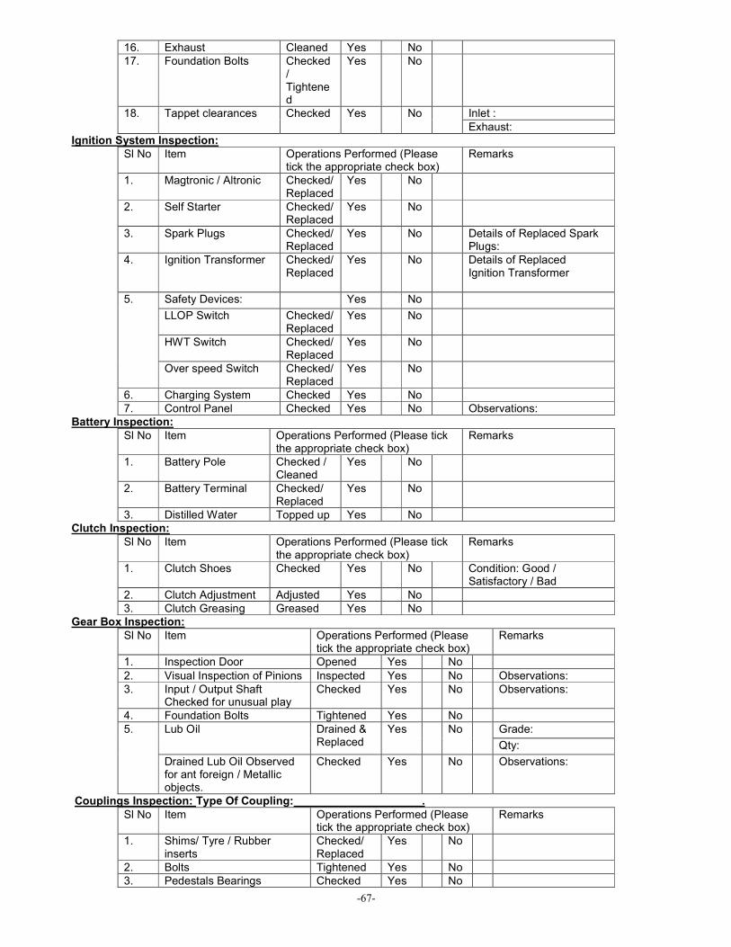
-67-
16. Exhaust Cleaned Yes No
17. Foundation Bolts Checked / Tightened
Yes No
Inlet : 18. Tappet clearances Checked Yes No
Exhaust:
Ignition System Inspection:
Sl No Item Operations Performed (Please tick the appropriate check box)
Remarks
1. Magtronic / Altronic Checked/ Replaced
Yes No
2. Self Starter Checked/ Replaced
Yes No
3. Spark Plugs Checked/ Replaced
Yes No Details of Replaced Spark Plugs:
4. Ignition Transformer Checked/ Replaced
Yes No Details of Replaced Ignition Transformer
Safety Devices: Yes No
LLOP Switch Checked/ Replaced
Yes No
HWT Switch Checked/ Replaced
Yes No
5.
Over speed Switch Checked/ Replaced
Yes No
6. Charging System Checked Yes No
7. Control Panel Checked Yes No Observations:
Battery Inspection:
Sl No Item Operations Performed (Please tick the appropriate check box)
Remarks
1. Battery Pole Checked / Cleaned
Yes No
2. Battery Terminal Checked/ Replaced
Yes No
3. Distilled Water Topped up Yes No
Clutch Inspection:
Sl No Item Operations Performed (Please tick the appropriate check box)
Remarks
1. Clutch Shoes Checked Yes No Condition: Good / Satisfactory / Bad
2. Clutch Adjustment Adjusted Yes No
3. Clutch Greasing Greased Yes No
Gear Box Inspection:
Sl No Item Operations Performed (Please tick the appropriate check box)
Remarks
1. Inspection Door Opened Yes No
2. Visual Inspection of Pinions Inspected Yes No Observations:
3. Input / Output Shaft Checked for unusual play
Checked Yes No Observations:
4. Foundation Bolts Tightened Yes No
Grade: Lub Oil Drained & Replaced
Yes No
Qty:
5.
Drained Lub Oil Observed for ant foreign / Metallic objects.
Checked Yes No Observations:
Couplings Inspection: Type Of Coupling: .
Sl No Item Operations Performed (Please tick the appropriate check box)
Remarks
1. Shims/ Tyre / Rubber inserts
Checked/ Replaced
Yes No
2. Bolts Tightened Yes No
3. Pedestals Bearings Checked Yes No
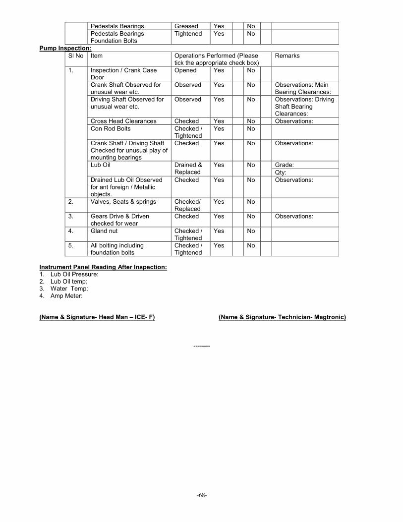
-68-
Pedestals Bearings Greased Yes No
Pedestals Bearings Foundation Bolts
Tightened Yes No
Pump Inspection:
Sl No Item Operations Performed (Please tick the appropriate check box)
Remarks
Inspection / Crank Case Door
Opened Yes No
Crank Shaft Observed for unusual wear etc.
Observed Yes No Observations: Main Bearing Clearances:
Driving Shaft Observed for unusual wear etc.
Observed Yes No Observations: Driving Shaft Bearing Clearances:
Cross Head Clearances Checked Yes No Observations:
Con Rod Bolts Checked / Tightened
Yes No
Crank Shaft / Driving Shaft Checked for unusual play of mounting bearings
Checked Yes No Observations:
Grade: Lub Oil Drained & Replaced
Yes No
Qty:
1.
Drained Lub Oil Observed for ant foreign / Metallic objects.
Checked Yes No Observations:
2. Valves, Seats & springs Checked/ Replaced
Yes No
3. Gears Drive & Driven checked for wear
Checked Yes No Observations:
4. Gland nut Checked / Tightened
Yes No
5. All bolting including foundation bolts
Checked / Tightened
Yes No
Instrument Panel Reading After Inspection: 1. Lub Oil Pressure: 2. Lub Oil temp: 3. Water Temp: 4. Amp Meter: (Name & Signature- Head Man – ICE- F) (Name & Signature- Technician- Magtronic)
--------
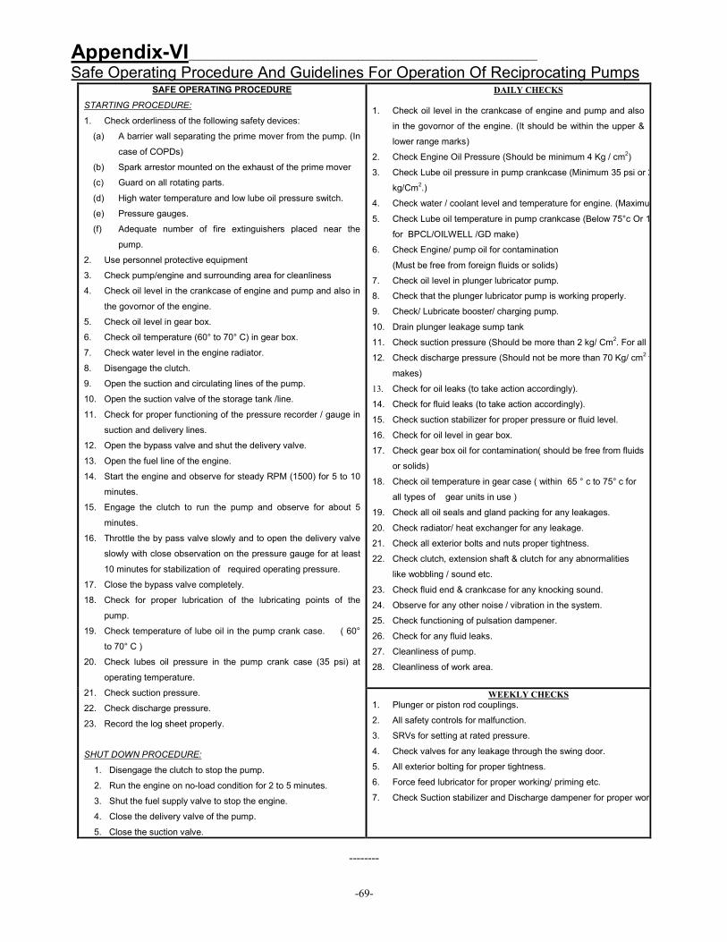
-69-
Appendix-VI______________________________________________________________________ Safe Operating Procedure And Guidelines For Operation Of Reciprocating Pumps
--------
DAILY CHECKS
1. Check oil level in the crankcase of engine and pump and also
in the govornor of the engine. (It should be within the upper &
lower range marks)
2. Check Engine Oil Pressure (Should be minimum 4 Kg / cm2)
3. Check Lube oil pressure in pump crankcase (Minimum 35 psi or 2.5
kg/Cm2.)
4. Check water / coolant level and temperature for engine. (Maximum 90
5. Check Lube oil temperature in pump crankcase (Below 75°c Or 167° F
for BPCL/OILWELL /GD make)
6. Check Engine/ pump oil for contamination
(Must be free from foreign fluids or solids)
7. Check oil level in plunger lubricator pump.
8. Check that the plunger lubricator pump is working properly.
9. Check/ Lubricate booster/ charging pump.
10. Drain plunger leakage sump tank
11. Check suction pressure (Should be more than 2 kg/ Cm2. For all make)
12. Check discharge pressure (Should not be more than 70 Kg/ cm2 for all
makes)
13. Check for oil leaks (to take action accordingly).
14. Check for fluid leaks (to take action accordingly).
15. Check suction stabilizer for proper pressure or fluid level.
16. Check for oil level in gear box.
17. Check gear box oil for contamination( should be free from fluids
or solids)
18. Check oil temperature in gear case ( within 65 ° c to 75° c for
all types of gear units in use )
19. Check all oil seals and gland packing for any leakages.
20. Check radiator/ heat exchanger for any leakage.
21. Check all exterior bolts and nuts proper tightness.
22. Check clutch, extension shaft & clutch for any abnormalities
like wobbling / sound etc.
23. Check fluid end & crankcase for any knocking sound.
24. Observe for any other noise / vibration in the system.
25. Check functioning of pulsation dampener.
26. Check for any fluid leaks.
27. Cleanliness of pump.
28. Cleanliness of work area.
SAFE OPERATING PROCEDURE
STARTING PROCEDURE:
1. Check orderliness of the following safety devices:
(a) A barrier wall separating the prime mover from the pump. (In
case of COPDs)
(b) Spark arrestor mounted on the exhaust of the prime mover
(c) Guard on all rotating parts.
(d) High water temperature and low lube oil pressure switch.
(e) Pressure gauges.
(f) Adequate number of fire extinguishers placed near the
pump.
2. Use personnel protective equipment
3. Check pump/engine and surrounding area for cleanliness
4. Check oil level in the crankcase of engine and pump and also in
the govornor of the engine.
5. Check oil level in gear box.
6. Check oil temperature (60° to 70° C) in gear box.
7. Check water level in the engine radiator.
8. Disengage the clutch.
9. Open the suction and circulating lines of the pump.
10. Open the suction valve of the storage tank /line.
11. Check for proper functioning of the pressure recorder / gauge in
suction and delivery lines.
12. Open the bypass valve and shut the delivery valve.
13. Open the fuel line of the engine.
14. Start the engine and observe for steady RPM (1500) for 5 to 10
minutes.
15. Engage the clutch to run the pump and observe for about 5
minutes.
16. Throttle the by pass valve slowly and to open the delivery valve
slowly with close observation on the pressure gauge for at least
10 minutes for stabilization of required operating pressure.
17. Close the bypass valve completely.
18. Check for proper lubrication of the lubricating points of the
pump.
19. Check temperature of lube oil in the pump crank case. ( 60°
to 70° C )
20. Check lubes oil pressure in the pump crank case (35 psi) at
operating temperature.
21. Check suction pressure.
22. Check discharge pressure.
23. Record the log sheet properly.
SHUT DOWN PROCEDURE:
1. Disengage the clutch to stop the pump.
2. Run the engine on no-load condition for 2 to 5 minutes.
3. Shut the fuel supply valve to stop the engine.
4. Close the delivery valve of the pump.
5. Close the suction valve.
WEEKLY CHECKS
1. Plunger or piston rod couplings.
2. All safety controls for malfunction.
3. SRVs for setting at rated pressure.
4. Check valves for any leakage through the swing door.
5. All exterior bolting for proper tightness.
6. Force feed lubricator for proper working/ priming etc.
7. Check Suction stabilizer and Discharge dampener for proper working.

-70-
Appendix- VII________________________________________________________________ Basics of Alignment What is alignment: Once all the recommendations are met for installation of a reciprocating pump, the unit ready to be coupled with the prime mover (Engine or Motor).Even after fulfilling all the criteria, we may not get the desired results like smooth operation, efficiency and better life if one vital point is overlooked: “ALIGNMENT” I.e.: The output shaft of the prime mover and the input shaft of the pump (if a gear box is in between then all the IP & OP shafts) is in a common center line. Types of Misalignment: Angular misalignment occurs when the prime mover is set at an angle to the driven equipment. The angle or mismatch can be to the left or the right, or above or below. If the centerlines of the prime mover and the driven equipment shafts were to be extended, they would cross each other, rather than superimpose or run along a common centerline. Angular misalignment can cause severe damage to the driven equipment and the prime mover. Parallel misalignment occurs when the two shaft centerlines are parallel, but not in the same line. They are offset horizontally or vertically (or both), displaced to the left or right, or positioned at different elevations. Combination misalignment occurs when the motor shaft suffers from angular misalignment in addition to parallel misalignment.
Methods for checking and correcting alignment:
� Straight Edge Method (for initial rough alignment only) � Dial Indicator Method � Laser Alignment Method.
Accurately aligned machinery will achieve the following results:
� Reduce excessive axial and radial forces on the bearings to insure longer bearing life and rotor stability under dynamic operating conditions
� Minimize the amount of shaft bending from the point of power transmission in the coupling to the coupling-end-bearing
� Minimize the amount of wear in the coupling components � Reduce mechanical seal failure � Maintain proper internal rotor clearances � Lower vibration levels in machine casings, bearing housings, and rotors
--------

-71-
Appendix- VIII __________________________________________________________________ Basic Maintenance Schedule for Gear Boxes
--------

-72-
Bibliography_______________________________________________________________________
1. The Reciprocating Pump: Theory, Design & Use: John E Miller.
2. Hydraulic Institute’s web portal.
3. Guidelines from O&M Manuals of GD, BPCL, National Oilwell and Cummins.
4. Indian Standard- IS: 11745.
5. Water Well and Pump Engineering: A M Michael & S D Khepkar.
--------


![oilweb.oilindia.in Date é¢~xNR6f Hû£ QW û o8 QëÝlú¤{ Ða» õ ] @YÀrÚgt](https://img.dokumen.tips/doc/110x75/5aff7bf77f8b9a444f904adc/-date-xnr6f-h-qw-o8-ql-a-yrgt.jpg)