Embed Size (px)
Citation preview

STRUCTURE GEOTECHNICAL REPORT
STEARNS ROAD BRIDGE OVER FOX RIVER
KANE COUNTY, ILLINOIS
IDOT STRUCTURE NUMBER 045-3166
KANE COUNTY PROJECT P-91-051-07
For:
Baker Engineering, Inc.
801 W. Adams Street
Chicago, IL 60607
(312) 707-8770
Submitted By:
Wang Engineering, Inc.
1145 North Main Street
Lombard, IL 60148
(630) 953-9928
March 10, 2008
WEI Ref. No. 707-11-01

Structure Geotechnical ReportResponsibility Checklist
Structure Number: 045-3166 (prop.) None (exist.) Contract Number: Date: 3/10/2008 Route: New Stearns Road Section: 98-00214-02BR County: Kane TSL plans by: Baker Engineering, Inc. 801 W Adams Street, Chicago, IL 60607 Structure Geotechnical Report and Checklist by: Wang Engineering, Inc., 1145 N. Main St; Lombard, Illinois 60148
IDOT Structure Geotechnical Report Approval Responsibility : Qualified District Geotechnical Personnel BBS Central Geotechnical Unit
Geotechnical Data, Subsurface Exploration and Testing Yes No N/A All pertinent existing boring data, pile driving data, site inspection information included in the report? ........Are the preliminary substructure locations, foundation needs, and project scope discussions between Geotechnical Engineer and Structure Planner included in the report? ..........................................................All ground and surface water elevations shown on all soil borings and discussed in the report?..................Has all existing and new exploration and test data been presented on a subsurface data profile? ..............Is the exploration and testing in accordance with the IDOT Geotechnical Manual policy?............................Are the number, locations, depths, sampling, testing, and subsurface data adequate for design?...............Geotechnical EvaluationsHave structure or embankment settlement amounts and times been discussed in report? ..........................Does the report provide recommendations/treatments to address settlement concerns?.............................Has the critical factor of safety against slope instability been identified and discussed in the report? ..........Does the report provide recommendations/treatments to address stability concerns? .................................Is the seismic design data (PGA, amplification, category, etc.) noted in the report?.....................................Have the vertical and horizontal limits of any liquefiable layers been identified and discussed? ..................Has seismic stability been discussed and have any slope deformation estimates been provided? ..............Has the report discussed the proximity of ISGS mapped mines or known subsidence events? ...................Has scour been discussed, any Hydraulics Report depths reported & soil type reductions made?..............Do the Factors of Safety meet AASHTO and IDOT policy requirements?.....................................................Geotechnical Analyses and Design RecommendationsWhen spread footings are recommended, has a bearing capacity and footing elevation been provided for each substructure or footing region?.........................................................................................................Has footing sliding capacity been discussed?................................................................................................When piles are recommended, does the report include a table indicating estimated pile lengths vs. a range of feasible required bearings and design capacities for each pile type recommended? .....................Have any downdrag, scour, and liquefaction reductions in pile capacity been addressed?..........................Will piles have sufficient embedment to achieve fixity and lateral capacity? .................................................Have the diameters & elevations of any pile pre-coring been specified (when recommended)? ..................Has the need for test piles been discussed and the locations specified (when recommended)?..................Has the need for metal shoes been discussed and specified (when recommended)?..................................When drilled shafts are recommended, have side friction and/or end-bearing values been provided? ........Has the feasibility of using belled shafts been discussed when terminating above rock, or have estimated top of rock elevations been provided when extending into rock?..................................................Have shaft fixity, lateral capacity, and min. embedment been discussed?....................................................When retaining walls are required, has feasibility and relative costs for various wall types been discussed?......................................................................................................................................................Have lateral earth pressures and backfill drainage recommendations been discussed? ..............................Has ground modification been discussed as a way to use a less expensive foundation or address feasibility concerns? .......................................................................................................................................Have any deviations from IDOT Geotechnical Manual or Bridge Manual policy been recommended? ........Construction ConsiderationsHas the need for cofferdams, seal coat, or underwater structure excavation protection been discussed?...Has stability of temporary construction slopes vs. the need for temporary walls been discussed?...............Has the feasibility of cantilevered sheeting vs. a temporary soil retention system been discussed? ............Has the feasibility of using a geotextile wall vs. a temp. MSE for any temp fill retention been noted?..........“In order to aid in determining the level of departmental review, please attach additional documentation or reference specific portions of the SGR to clarify any checklist responses that reflect deviation from IDOT policy/practice.”
BBS-2602 (4/05) ISO BBSF-710-003

Geotechnical • Construction • Environmental Quality Engineering Services Since 1982
TABLE OF CONTENTS
1.0 INTRODUCTION ...................................................................................................................... 12.0 PROJECT DESCRIPTION....................................................................................................... 13.0 EXISTING AND PROPOSED STRCUTURES ...................................................................... 14.0 PURPOSE AND SCOPE............................................................................................................ 35.0 GEOLOGIC SETTING ............................................................................................................. 35.1 BEDROCK GEOLOGY .............................................................................................................................................. 35.2 SURFICIAL GEOLOGY ............................................................................................................................................. 45.3 MINING ACTIVITY.................................................................................................................................................. 55.4 SEISMIC ACTIVITY ................................................................................................................................................. 5
6.0 METHODS OF INVESTIGATION.......................................................................................... 56.1 SUBSURFACE INVESTIGATION ................................................................................................................................ 5
6.1.1. Existing Subsurface Data ................................................................................................................................. 56.1.2 Borings by WEI................................................................................................................................................. 56.1.3 Pressuremeter Testing ...................................................................................................................................... 7
6.2 LABORATORY TESTING.......................................................................................................................................... 7
7.0 SITE AND SUBSURFACE CONDITIONS............................................................................. 87.1 SITE CONDITIONS................................................................................................................................................... 87.2 SUBSURFACE CONDITIONS ..................................................................................................................................... 97.3 GROUNDWATER LEVELS ...................................................................................................................................... 107.4 SEISMIC CONSIDERATIONS................................................................................................................................... 10
7.4.1 Seismic Data................................................................................................................................................... 107.4.2 Liquefaction Potential .................................................................................................................................... 11
8.0 ANALYSIS AND RECOMMENDATIONS .......................................................................... 118.1 FOUNDATION RECOMMENDATIONS...................................................................................................................... 118.2 DOWNDRAG LOADS .............................................................................................................................................. 138.3 LATERAL DESIGN PRESSURES ............................................................................................................................... 148.4 RESISTANCE TO LATERAL LOADS.......................................................................................................................... 148.5 SCOUR POTENTIAL................................................................................................................................................ 148.6 FOUNDATION SETTLEMENT................................................................................................................................... 158.7 EMBANKMENT SLOPE STABILITY .......................................................................................................................... 158.8 EMBANKMENT SETTLEMENT................................................................................................................................. 15
9.0 CONSTRUCTION CONSIDERATIONS ............................................................................... 179.1 EXCAVATION........................................................................................................................................................ 179.2 DEWATERING ....................................................................................................................................................... 179.3 FILLING AND BACKFILLING ................................................................................................................................... 179.4 COFFERDAM ......................................................................................................................................................... 189.5 DRILLED SHAFTS .................................................................................................................................................. 189.6 CONSTRUCTION MONITORING............................................................................................................................... 189.7 EMBANKMENT CONSTRUCTION............................................................................................................................. 18
Geotechnical • Construction • Environmental Quality Engineering Services Since 1982
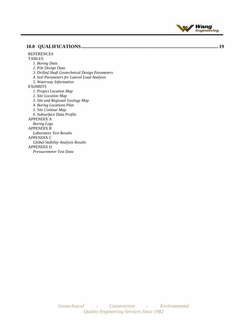
10.0 QUALIFICATIONS................................................................................................................. 19REFERENCESTABLES
1. Boring Data2. Pile Design Data3. Drilled Shaft Geotechnical Design Parameters4. Soil Parameters for Lateral Load Analysis5. Waterway Information
EXHIBITS1. Project Location Map2. Site Location Map3. Site and Regional Geology Map4. Boring Locations Plan5. Site Contour Map6. Subsurface Data Profile
APPENDIX ABoring Logs
APPENDIX BLaboratory Test Results
APPENDIX CGlobal Stability Analysis Results
APPENDIX DPressuremeter Test Data

1145 North Main Street Lombard, Illinois 60148
Phone (630) 953-9928 www.wangeng.com
Geotechnical • Construction • Environmental Quality Engineering Services Since 1982
STRUCTURE GEOTECHNICAL REPORT NEW STEARNS ROAD BRIDGE OVER FOX RIVER
IDOT STRUCTURE NUMBER 045-3166 KANE COUNTY PROJECT NO. P-91-051-07
FORBAKER ENGINEERING, INC.
1.0 INTRODUCTION
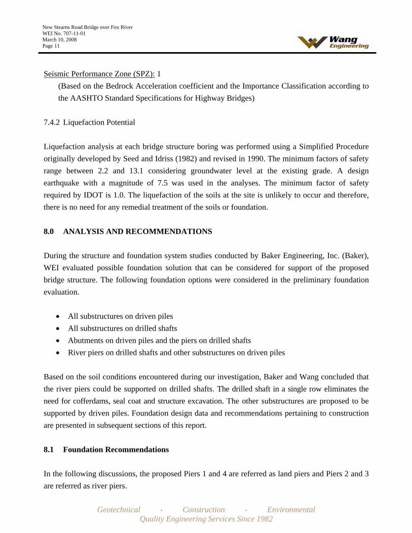
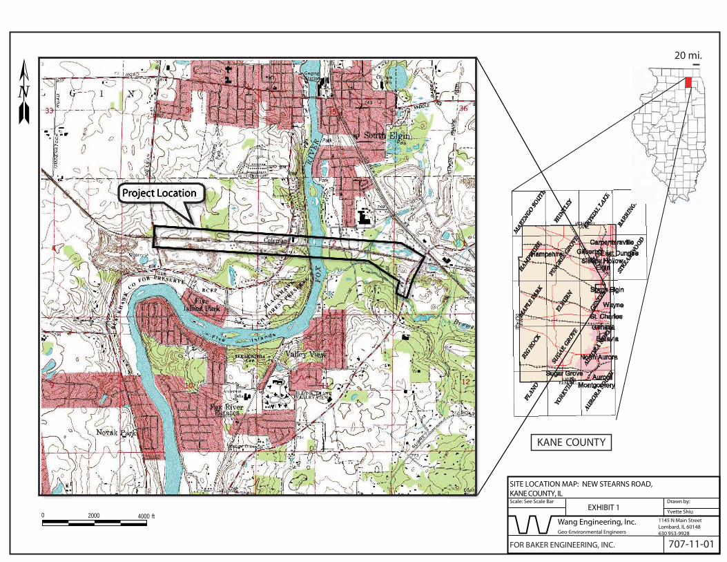
This report presents the results of subsurface investigation, laboratory testing, and geotechnical evaluation for the proposed New Stearns Road Bridge over Fox River. The project site is located in Kane County, Illinois. The Project and Site Location Maps are presented as Exhibits 1 and 2.
2.0 PROJECT DESCRIPTION
The Stearns Road Corridor will include a new Fox River Bridge and a 4.6 mile new road alignment that extends from approximately the Kane/DuPage County line to Randall Road. The Contract 4 scope of work includes construction of the new Stearns Road from east of McLean Boulevard to Illinois Route 25 including new structure over Fox River.
The proposed typical cross section consists of two 12 foot lanes in each direction separated by an 8 to 32 foot median. Signalized intersection improvements will be provided at Randall Road/McDonald Road (the western terminus), McLean Boulevard, Illinois Route 25, Gilbert Street, and Dunham Road. The proposed roadway continues east of the intersection to join the four lane section of Stearns Road completed by DuPage County.
3.0 EXISTING AND PROPOSED STRCUTURES
This is a new bridge. There are no river crossings within the 5.5 miles from the Illinois Route 64 Bridge in the City of St. Charles to the State Street Bridge in the Village of South Elgin. The nearest existing crossing of the Fox River to the project is a railroad bridge. The proposed Stearns Road bridge crossing is located approximately 240 feet south of the Canadian National Illinois Central Railroad (CNICRR) Bridge. No information was available for this bridge structure foundation.

New Stearns Road Bridge over Fox River WEI No. 707-11-01 March 10, 2008 Page 2
Geotechnical • Construction • Environmental Quality Engineering Services Since 1982
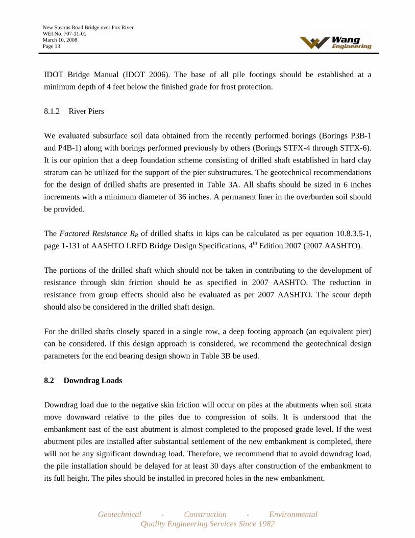
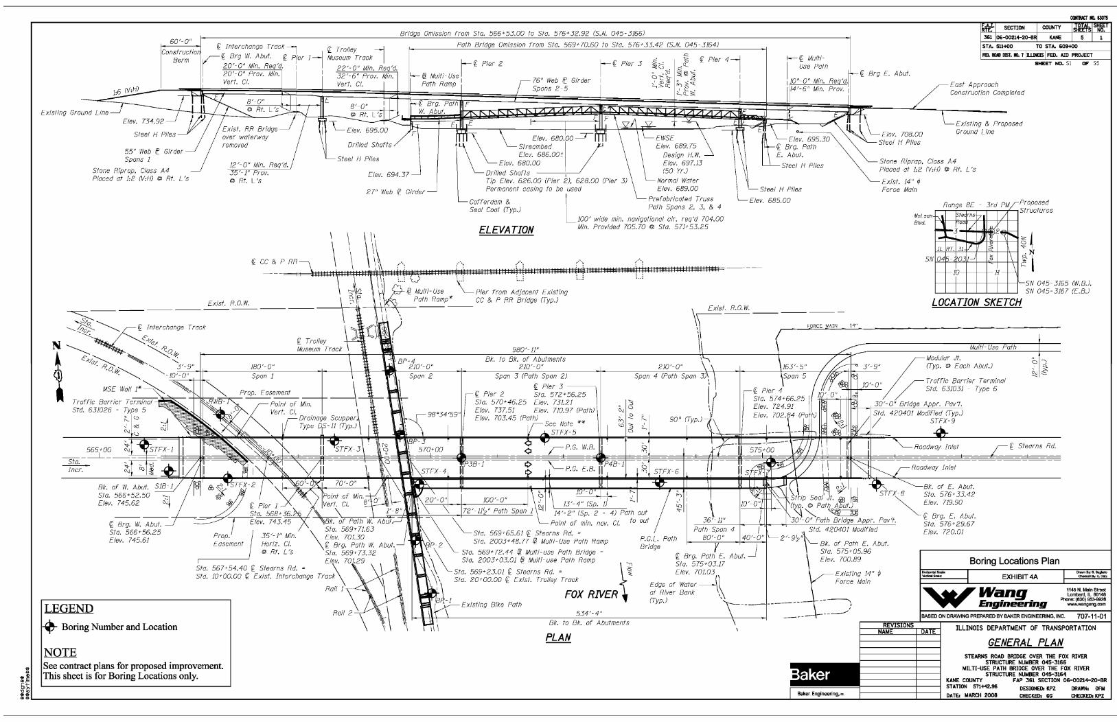
The proposed bridge structures will be a 5-span steel plate girder structure with cast-in-place concrete deck. The bridge will carry four 12-foot lanes in each direction with a 2-foot outside and inside shoulder as well as a 4-foot median. The structure will be 63’-2” wide out-to-out and 980’-11” long back-to-back abutments. The structure will require three spans to cross the Fox River. The span lengths measured along the Proposed Grade Line (PGL) are 180’ for span 1, 210’ for spans 2 and 4, and 163’-5” for span 5. Two piers will be located in the river. Both the abutments and piers 1, 3, and 4 are expansion type and pier 2 will be fixed. The abutments will be stubtype abutments. The substructure locations are shown in Exhibit 4, Boring Location Plan.
The preliminary estimated substructure LRFD factored loads have been provided by Baker Engineering, Inc. (Baker) at the sub-structures. They are as follow:
West Abutment Vertical Load 2500 k
Pier 1 Vertical Load 7200 k Moment 5700 k-ft
Piers 2 Vertical Load 7500 k Moment 7500 k-ft
Piers 3 Vertical Load 7500 k Moment 7200 k-ft
Pier 4 Vertical Load 7000 k Moment 4650
East Abutment Vertical Load 2500 k
A Mixed-use path ramp structure is proposed along the Fox River and under the proposed river bridge on the east side of the Fox River. A new retaining wall is proposed to be located parallel to the Interchange railroad track at northeast of the west abutment of the river bri8dge. A separate Structure Geotechnical Report will be prepared for these two structures.

New Stearns Road Bridge over Fox River WEI No. 707-11-01 March 10, 2008 Page 3
Geotechnical • Construction • Environmental Quality Engineering Services Since 1982
4.0 PURPOSE AND SCOPE
The purpose of our geotechnical work was to investigate and evaluate the subsurface soil and groundwater conditions within this project area that would form a basis for foundation and earthwork design recommendations. Specifically, the scope of the work was as follows:
To investigate by means of supplemental exploratory borings, the subsurface soils and ground water level conditions at the site to depths that will be influenced by the proposed construction;To evaluate the physical properties of the soils underlying the site that will influence foundation design and construction; To perform analyses and provide recommendations and data for the design and installation of foundations, including the suitable foundation type or types, bearing capacity, the elevation or elevations at which the foundations should be established, and the estimated foundation settlement; To provide recommendations relative to construction operations and special design precaution that may be required; and To provide a report summarizing the results of our studies, conclusions, and recommendations.
5.0 GEOLOGIC SETTING
The project is located in the eastern part of Kane County. On the USGS “Geneva” quadrangle map, the project spans mainly sections 2 and 3 of Tier 40 N Range 8 E. The proposed bridge over the Fox River is located in the center of Section 2 as shown in Exhibit 2.
The following review of published geologic data, with emphasis on factors that might influence the design and construction of the proposed engineering works, intends to place the project area within a geological framework and to confirm the dependability and consistency of our investigation results. Exhibit 3 illustrates the Site and Regional Geology.
5.1 Bedrock Geology
The uppermost bedrock unit in Kane County consists of Silurian-age dolostones that rest on top of Ordovician-age shale and dolostone of the Maquoketa Group. The bedrock strata dip gently toward southeast (Curry et al., 1999; Dey et al., 2007).

New Stearns Road Bridge over Fox River WEI No. 707-11-01 March 10, 2008 Page 4
Geotechnical • Construction • Environmental Quality Engineering Services Since 1982
The bedrock crops out along the Fox River just south of the McLean Boulevard and IL-31 intersection. At the project site, the proglacial St. Charles Bedrock Valley shapes the bedrock topography: the valley is oriented NNE to SSW and has a relief of about 100 feet. The McLean Boulevard and IL 31 intersection is located above the western bank of the bedrock valley, whereas the proposed bridge over the Fox River lies above the valley’s axis where the top of bedrock elevation measures 575 to 550 feet. The valley fill includes up to 100 feet of glacial outwash and till (Dey et al., 2007; Grimley and Curry, 2002).
5.2 Surficial Geology
Glacial and postglacial deposits overlie the bedrock surface. Near the project area, the glacial deposits include diamictons of the Yorkville Member of the Lemont Formation and sand and gravel of the Henry Formation (Hansel and Johnson, 1996). Postglacial deposits are made up of sand and silt alluvium deposited by the Fox River (Cahokia Formation) and peat and muck accumulated in marshy depressions (Grayslake Peat).
The Yorkville Member consists of low moisture content, high blow counts, low compressibility silty to silty clay loam diamicton (Bauer et al., 1991). It occurs at the east end of the project area and its thickness may range between 0 and 50 feet. The Yorkville Member rests over and it is overlain by medium dense to dense sand and gravel of the Henry Formation, which makes up most of the subgrade in the project area and may be as thick as 75 feet. Older diamictons may underline both the Yorkville Member and the Henry Formation (Grimley and Curry, 2002).
Less than 20-foot thick Cahokia alluvium (sand, silt, and clay) occurs in the project area, mostly east of the Fox River. A prominent deposit of peat, muck, organic silt and clay associated with the Grayslake Peat occur within a fen area just west of McLean Boulevard (Grimley and Curry, 2002).
Our and previous subsurface investigations result fit into the local geologic context. The investigation revealed the lithological profile includes mostly outwash sand and gravel and clayey to silty diamictons. None of the borings drilled near the proposed bridge location reached the top of the bedrock.

New Stearns Road Bridge over Fox River WEI No. 707-11-01 March 10, 2008 Page 5
Geotechnical • Construction • Environmental Quality Engineering Services Since 1982
5.3 Mining Activity
Areas of disturbed ground with spoil piles or removed earth in gravel pits, dolostone quarries, and landfills are present within or near the project area. Fox River Quarry (crushed stone) is located at the west end of the project. Another area with disturbed ground, probably associated with the Elgin-Wayne Landfill, is located at the east end of the project area. There were no past coal mining activities at the proposed structure location. The Kane County is not identified as coal producing area by Illinois State Geological Survey (ISGS, 2000).
5.4 Seismic Activity
The 2002 US Geological Survey National Seismic Hazard Map (USGS, 2002) indicates for the Kane County area a peak ground acceleration of 2% of gravity, with a 10% probability of exceedance in 50 years. No active, major faults are present near the project area (Kolata, 2005).
6.0 METHODS OF INVESTIGATION
6.1 Subsurface Investigation
6.1.1. Existing Subsurface Data
During the Phase I, Testing Services Corporation (TSC) performed a total of 9 structure borings (STFX-1 to STFX-9) between stations 565+50 to 578+00 and spaced 150 feet interval. Three of these borings (STFX-4 to STFX-6) were located in the Fox River. The termination depths of these borings were between 70 to 100 feet below ground surface (bgs). Borings locations are shown in Exhibit 4. Boring logs are included in Appendix A.
6.1.2 Borings by WEI
The subsurface exploration performed by WEI for the Fox River Bridge consisted of two structure borings (P3B-1 and P4B-1) at the proposed piers 2 and 3 locations in the Fox River and one structure boring (S1B-1) at the west abutment location. Borings were drilled during the period of November 29 and December 13, 2007. The borings in the Fox River, the bridge west abutment, and Pier 1 were located and marked with metal posts by Christopher B. Burke Engineering Ltd. (CBBE). Boring S1B-1 was located in the field by WEI by measuring off the proposed distances

New Stearns Road Bridge over Fox River WEI No. 707-11-01 March 10, 2008 Page 6
Geotechnical • Construction • Environmental Quality Engineering Services Since 1982
from the marked Pier 1 and bridge west abutment locations. Boring S1B-1 was surveyed by CBBE after the drilling completion. As-drilled borings locations for the river borings were determined by measuring the offset from the surveyed boring locations. A Boring Locations Plan is included as Exhibit 4. The survey information (ground surface elevation, coordinates, stations and offset) provided by CBBE is included in the attached boring logs (Appendix A).
An all terrain vehicle (ATV) mounted drilling rig, equipped with hollow stem augers, was used to advance and maintain an open borehole. Because the water in the Fox River was shallow enough, the ATV rig was also used to drill the river borings. To minimize wandering off the borehole while drilling the river borings, a platform on wheels with a guide hole for the augers was used and placed perpendicular to the river current by the ATV drill rig. A second ATV with a cage was used to contain and transport the pressuremeter equipment, to transport the trailer containing the drilling equipment, and to obtain the results from the in field unconfined compressive strengths and pressure meter tests. Soil sampling was performed according to AASHTO T 206-87, "Penetration Test and Split Barrel Sampling of Soils."
The soil at Boring S1B-1 was sampled at 2.5-foot intervals to a depth of 30 feet and at 5-foot intervals below 30 feet to termination depths. The soil at borings P3B-1 and P4B-1 was sampled at 2.5-foot intervals to a depth of 30 feet and at 5-foot intervals below 30 feet until cohesive material was encountered. Once cohesive material was encountered, drilling continued using a mud rotary system, soil was sampled at 5-foot intervals, and each cohesive sample was immediately followed with a pressuremeter test. Borings were drilled few feet deeper than required in order to obtain necessary information for an adequate engineering analysis. Borings were drilled to depths ranging from 74 to 92 feet bgs.
A WEI field engineer monitored the drilling activities and maintained field boring logs. The field logs included results of Standard Penetration Test (SPT) recorded as blows per 6 inches of penetration. Theses values are shown on the boring logs as SPT values. The N value is the sum of the last two SPT numbers (blows per final 12 inches). The unconfined compressive strengths of cohesive soil samples were obtained in the field using Rimac Spring Tester on the split spoon samples. The soils were described and classified according to IDH classification system.
All soil samples collected in the field were placed in sealed glass jars and transported to WEI Geotechnical Laboratory in Lombard, Illinois for further laboratory testing and examination. The

New Stearns Road Bridge over Fox River WEI No. 707-11-01 March 10, 2008 Page 7
Geotechnical • Construction • Environmental Quality Engineering Services Since 1982
field logs were finalized by an experienced geologist after verifying the field visual classifications and laboratory test results.
The soil samples will be retained in our laboratory for 60 days following the final report submittal. The samples will be discarded unless a specific written request is received as to their disposition.
Groundwater observations were made during and at the end of drilling operations. Due to safety considerations, the land borehole was backfilled with bentonite chips mixed with soil cuttings immediately upon completion. The boreholes in the river were backfilled with the mud from the mud rotary drilling system and with granular cave-in material from the borehole’s upper most layers.
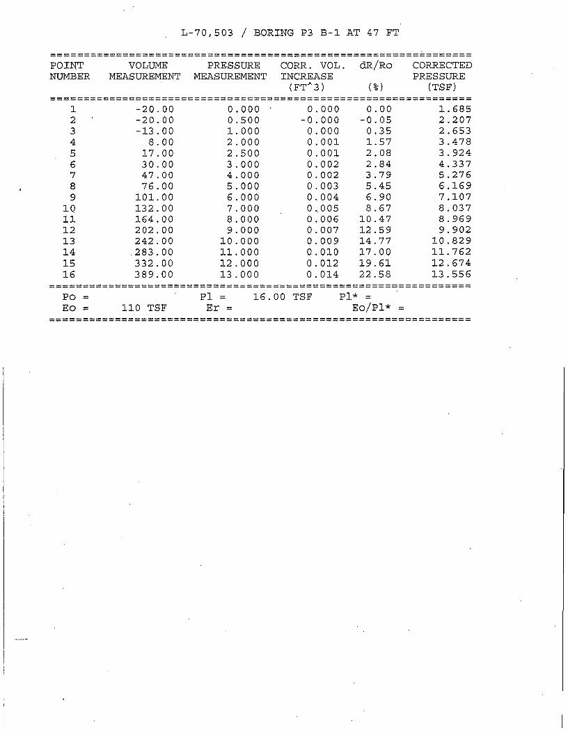
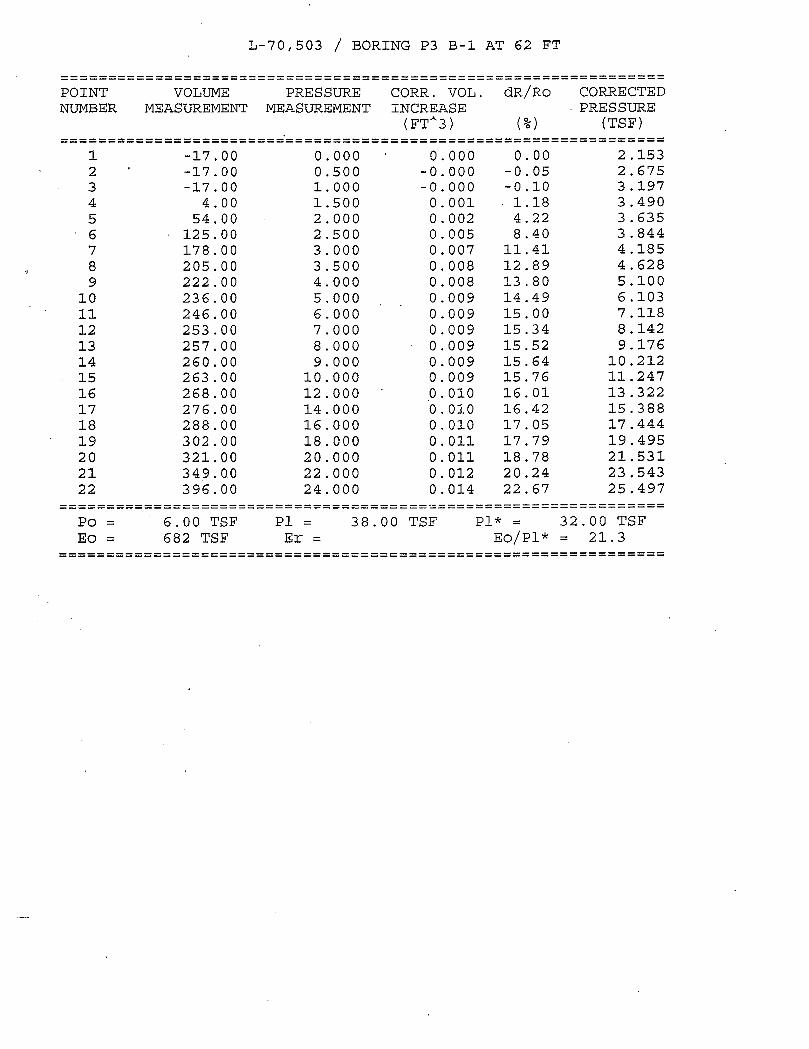
6.1.3 Pressuremeter Testing
A Menard Pressuremeter, Model G-AM II manufactured by RocTest Ltd. was used to measure the in-situ strength and stress-strain soil properties. Pressuremeter testing was conducted in Borings P3B-1 and P4B-1 from depths of 43 feet to 68 feet bgs at intervals of 5 feet. The pressuremeter tests were performed during the period of November 29 through December 6, 2007. . Split spoon samples were obtained before performing in-situ pressuremeter testing for laboratory testing and to determine the interval at which the pressuremeter testing should be performed. Upon obtaining a split spoon sample of cohesive material, the borehole was redrilled at that same sample interval using a mud rotary drill bit to widen the borehole walls to a calculated diameter that is slightly larger than the pressuremeter probe. On the cohesive split spoon soil samples, unconfined compressive strengths were obtained in the field using a Rimac Spring Tester. These values were used as a guideline when calculating the pressure to be applied at each pressuremeter test interval. The results of pressuremeter tests are included in Appendix D.
6.2 Laboratory Testing
Laboratory testing program included moisture content (AASHTO T 265) on all the soil samples. Atterberg Limits tests (AASHTO T 89 & T 90) and particle-size analyses (AASHTO T 88) were performed on selected soil samples. The field visual descriptions of the samples were reviewed in the laboratory. The laboratory test results are presented on the boring logs (Appendix A) and included in Appendix B.
New Stearns Road Bridge over Fox River WEI No. 707-11-01 March 10, 2008 Page 8
Geotechnical • Construction • Environmental Quality Engineering Services Since 1982
7.0 SITE AND SUBSURFACE CONDITIONS
7.1 Site Conditions
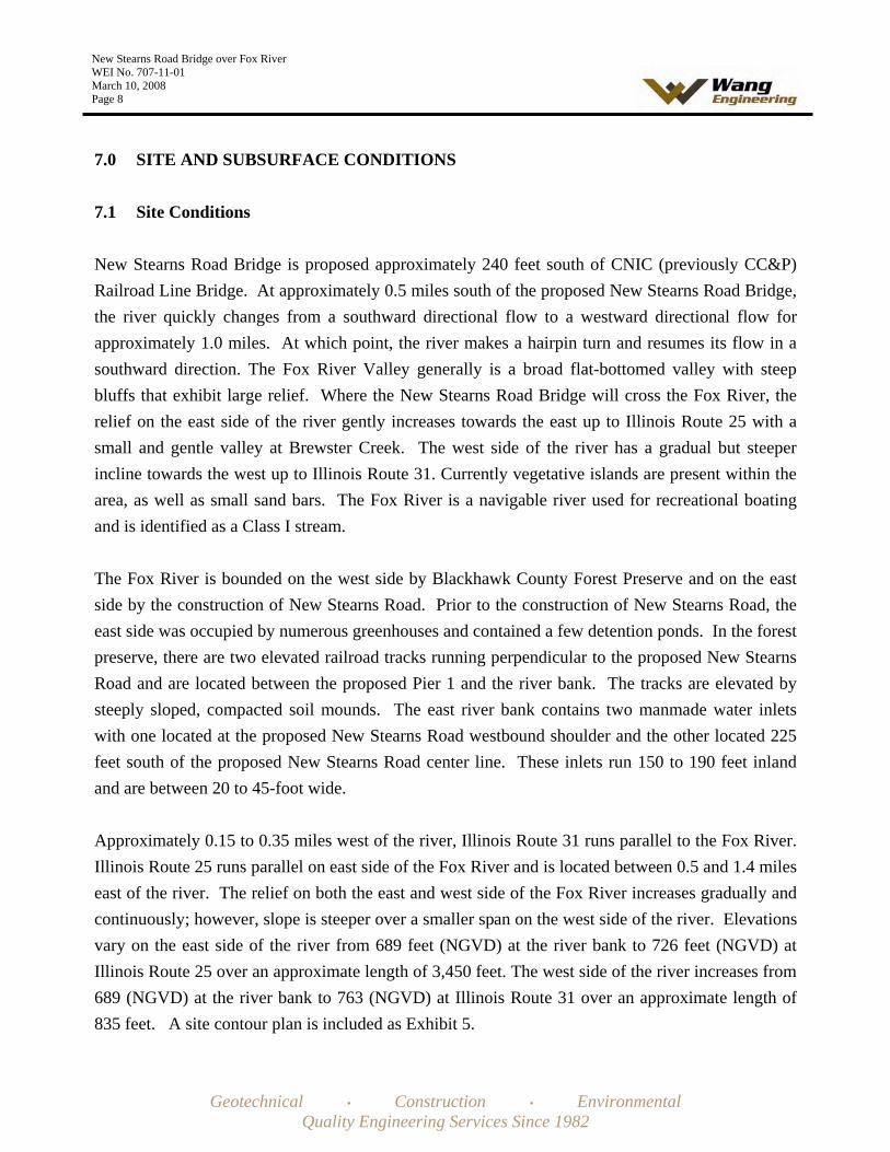
New Stearns Road Bridge is proposed approximately 240 feet south of CNIC (previously CC&P) Railroad Line Bridge. At approximately 0.5 miles south of the proposed New Stearns Road Bridge, the river quickly changes from a southward directional flow to a westward directional flow for approximately 1.0 miles. At which point, the river makes a hairpin turn and resumes its flow in a southward direction. The Fox River Valley generally is a broad flat-bottomed valley with steep bluffs that exhibit large relief. Where the New Stearns Road Bridge will cross the Fox River, the relief on the east side of the river gently increases towards the east up to Illinois Route 25 with a small and gentle valley at Brewster Creek. The west side of the river has a gradual but steeper incline towards the west up to Illinois Route 31. Currently vegetative islands are present within the area, as well as small sand bars. The Fox River is a navigable river used for recreational boating and is identified as a Class I stream.
The Fox River is bounded on the west side by Blackhawk County Forest Preserve and on the east side by the construction of New Stearns Road. Prior to the construction of New Stearns Road, the east side was occupied by numerous greenhouses and contained a few detention ponds. In the forest preserve, there are two elevated railroad tracks running perpendicular to the proposed New Stearns Road and are located between the proposed Pier 1 and the river bank. The tracks are elevated by steeply sloped, compacted soil mounds. The east river bank contains two manmade water inlets with one located at the proposed New Stearns Road westbound shoulder and the other located 225 feet south of the proposed New Stearns Road center line. These inlets run 150 to 190 feet inland and are between 20 to 45-foot wide.
Approximately 0.15 to 0.35 miles west of the river, Illinois Route 31 runs parallel to the Fox River. Illinois Route 25 runs parallel on east side of the Fox River and is located between 0.5 and 1.4 miles east of the river. The relief on both the east and west side of the Fox River increases gradually and continuously; however, slope is steeper over a smaller span on the west side of the river. Elevations vary on the east side of the river from 689 feet (NGVD) at the river bank to 726 feet (NGVD) at Illinois Route 25 over an approximate length of 3,450 feet. The west side of the river increases from 689 (NGVD) at the river bank to 763 (NGVD) at Illinois Route 31 over an approximate length of 835 feet. A site contour plan is included as Exhibit 5.

New Stearns Road Bridge over Fox River WEI No. 707-11-01 March 10, 2008 Page 9
Geotechnical • Construction • Environmental Quality Engineering Services Since 1982
7.2 Subsurface Conditions
Detailed descriptions of the subsurface conditions encountered in the borings are presented on the attached boring logs (Appendix A) and Subsurface Data Profile (Exhibit 6). Please note that the strata contact lines shown on logs and profiles represent approximate boundaries between soil types. The actual transition between soil types in the field may be different in horizontal and vertical directions.
The subsurface investigation uncovered a vertical sequence of soil units laterally traceable throughout Borings STFX-1 through STFX-9, P3B-1 through P4B-1, and S1B-1. From top to bottom, the sequence consists of three lithological units: (1) brown and gray sand to sandy gravel; (2) brown and gray clay to clay loam; and (3) brown and gray sand to sandy gravel. Due to the higher ground elevations at STFX-1 to STFX-3, STFX-9 and S1B-1, these borings were terminated in the second lithological unit; therefore, the third unit was not able to be verified at these locations. The following presents in further detail the soil profile and groundwater conditions, as revealed through drilling at the bridge abutments and piers.
The top unit consists of alternating layers of medium dense to very dense, brown and gray, gravelly sand and fine to coarse sand. The thickness ranges from 23 to 42 feet in Borings STFX-5 to STFX-9, P3B-1 and P4B-1. The thickness of the layer increases in range from 47 to 76 feet in STFX-1 to STFX-4 and S1B-1. Within the sand and gravel, there are lenses and layers of cohesive material ranging from 1 to 12.5 feet thick and are comprised of stiff to hard clay, silty clay, sandy clay and clay loam. Additionally, there are lenses of medium dense to dense silt ranging from 1 to 2.5 feet thick in borings STFX-1, STFX-6, STFX-7, and STFX-9.
Underlying the sand and gravel unit is a unit of very stiff to very hard, brown and gray clay to clay loam. This unit contains lenses of medium dense to very dense, fine to medium sand ranging from 1 to 5 feet thick at borings P3B-1, STFX-5 and STFX-7. At STFX-8, there is a 5 foot thick layer of dense silt.
The thickness of the third unit has minimum thicknesses of 3 to 25 feet and has an undetermined maximum thickness. The soil encountered in this unit is dense to very dense, brown and gray, fine sand to gravelly sand, gravel, silt and occasional cobbles. There is a 1 to 2-foot thick lens of very stiff to hard, clay to silty clay encountered at borings STFX-4, P3B-1, and P4B-1. The summary of the boring data is shown in Table 1.

New Stearns Road Bridge over Fox River WEI No. 707-11-01 March 10, 2008 Page 10
Geotechnical • Construction • Environmental Quality Engineering Services Since 1982
Bedrock was not encountered in any of the borings. The bedrock is estimated to be at a depth of 120 feet below the river bed and the borings were only extended to a maximum depth of 92 feet bgs. This would place the bedrock immediately below the silt that was encountered in STFX-4. Details on the type of bedrock expected to be encountered in this area is presented in Section 5.1 Bedrock Geology of this report.
7.3 Groundwater Levels
Water levels in the river borings (STFX-4 to STFX-6, P3B-1, and P4B-1) could not be recorded since they were drilled in the river. While drilling P3B-1 and P4B-1, the height of the surface river water was measured in reference to the river bed elevation and was approximately 1.5 feet above the ground surface at an estimated elevation of 688.5 (NGVD). Due to the erosion and deposition of material in the river and seasonal changes, we expect the Fox River water surface elevation will fluctuate.
While drilling, water levels were recorded in borings that were drilled outside the river. Water levels at various times after drilling completion were also observed in some of the borings. Water level observations are shown on the boring logs. In general, groundwater was encountered at elevations ranging between 685.5 and 689.2 feet while drilling. At the completion of drilling, groundwater levels were found at elevations ranging from 686.5 to 701.1 feet. We expect that the groundwater levels will fluctuate seasonally and with Fox River surface water level.
7.4 Seismic Considerations
7.4.1 Seismic Data
The following seismic data is recommended for the design which should be shown on the bridge plans.
Soil Profile Type: I (According to AASHTO Standard Specifications for Highway Bridges)
Bedrock Acceleration Coefficient (A): 0.038g(According to the AASHTO Seismic Acceleration Coefficient Map)
The Site Coefficient (S): 1.0(Based on Soil Profile Type I)
New Stearns Road Bridge over Fox River WEI No. 707-11-01 March 10, 2008 Page 11
Geotechnical • Construction • Environmental Quality Engineering Services Since 1982
Seismic Performance Zone (SPZ): 1 (Based on the Bedrock Acceleration coefficient and the Importance Classification according to the AASHTO Standard Specifications for Highway Bridges)
7.4.2 Liquefaction Potential
Liquefaction analysis at each bridge structure boring was performed using a Simplified Procedure originally developed by Seed and Idriss (1982) and revised in 1990. The minimum factors of safety range between 2.2 and 13.1 considering groundwater level at the existing grade. A design earthquake with a magnitude of 7.5 was used in the analyses. The minimum factor of safety required by IDOT is 1.0. The liquefaction of the soils at the site is unlikely to occur and therefore, there is no need for any remedial treatment of the soils or foundation.
8.0 ANALYSIS AND RECOMMENDATIONS
During the structure and foundation system studies conducted by Baker Engineering, Inc. (Baker), WEI evaluated possible foundation solution that can be considered for support of the proposed bridge structure. The following foundation options were considered in the preliminary foundation evaluation.
All substructures on driven piles All substructures on drilled shafts Abutments on driven piles and the piers on drilled shafts River piers on drilled shafts and other substructures on driven piles
Based on the soil conditions encountered during our investigation, Baker and Wang concluded that the river piers could be supported on drilled shafts. The drilled shaft in a single row eliminates the need for cofferdams, seal coat and structure excavation. The other substructures are proposed to be supported by driven piles. Foundation design data and recommendations pertaining to construction are presented in subsequent sections of this report.
8.1 Foundation Recommendations
In the following discussions, the proposed Piers 1 and 4 are referred as land piers and Piers 2 and 3 are referred as river piers.

New Stearns Road Bridge over Fox River WEI No. 707-11-01 March 10, 2008 Page 12
Geotechnical • Construction • Environmental Quality Engineering Services Since 1982
8.1.1 Abutments and Land Piers
The metal shell cast-in-place (MSCIP) pile driving through very dense/hard soils will be difficult and could damage the pile toe and cause deformation at the pile head. Therefore, we do not recommend MSCIP concrete piles for the abutments and land piers.
The top of the dolomitic limestone bedrock is estimated at approximate Elevation 570. The pile length from the bottom of the pile cap to top of the limestone bedrock would be 140 to 165 feet for the abutments and 115 to 135 feet for the piers. Based on the soil information from the borings, it appears that the driving of H-piles to top of bedrock, through very dense/very hard soils, will be very difficult and the refusal will be obtained before reaching top of the bedrock. Therefore, we do not recommend utilizing end bearing H-piles. The required driven capacity for steel H-piles installed as friction piles could be achieved with shorter lengths.
Several H-piles options for the foundations could be considered. Driven H-pile foundations could be designed for various capacities. The pile capacity will be developed in skin friction between the pile surface and the soils above the tip with some end bearing capacity at the tip.
The estimated pile lengths at each substructure location for various H-pile sizes and capacities are shown in Tables 2A through 2D. The most economical pile sizes should be selected. The sections of the pile through the precored holes in the newly placed embankment were not considered in providing vertical pile load carrying capacity. Precoring is recommended to avoid downdrag load on the piles and is discussed in the subsequent section of the report. The maximum structural design capacity of the steel pile and the spacing should be as per IDOT Bridge Manual (IDOT 2006). Hard pile driving during installation might be experienced in very dense sand and gravel deposits containing potentially cobbles. Therefore, we recommend that the piles be installed with metal shoes. It is our opinion that HP 12x53 or HP 14x73 piles be considered for the abutments and HP 12x74 or HP 14x89 for the piers. One test pile should be identified on the plans at each substructure which should be installed prior to production pile installation. There is no need for a full scale load test.
The soil immediately below the pile cap should not be considered as carrying any vertical load. The estimated lengths shown in the tables do not include any embedment into the pile cap footing. The estimated length to be shown on the bridge plans should include embedment in to the pile cap as per
New Stearns Road Bridge over Fox River WEI No. 707-11-01 March 10, 2008 Page 13
Geotechnical • Construction • Environmental Quality Engineering Services Since 1982
IDOT Bridge Manual (IDOT 2006). The base of all pile footings should be established at a minimum depth of 4 feet below the finished grade for frost protection.
8.1.2 River Piers
We evaluated subsurface soil data obtained from the recently performed borings (Borings P3B-1 and P4B-1) along with borings performed previously by others (Borings STFX-4 through STFX-6). It is our opinion that a deep foundation scheme consisting of drilled shaft established in hard clay stratum can be utilized for the support of the pier substructures. The geotechnical recommendations for the design of drilled shafts are presented in Table 3A. All shafts should be sized in 6 inches increments with a minimum diameter of 36 inches. A permanent liner in the overburden soil should be provided.
The Factored Resistance RR of drilled shafts in kips can be calculated as per equation 10.8.3.5-1, page 1-131 of AASHTO LRFD Bridge Design Specifications, 4th Edition 2007 (2007 AASHTO).
The portions of the drilled shaft which should not be taken in contributing to the development of resistance through skin friction should be as specified in 2007 AASHTO. The reduction in resistance from group effects should also be evaluated as per 2007 AASHTO. The scour depth should also be considered in the drilled shaft design.
For the drilled shafts closely spaced in a single row, a deep footing approach (an equivalent pier) can be considered. If this design approach is considered, we recommend the geotechnical design parameters for the end bearing design shown in Table 3B be used.
8.2 Downdrag Loads
Downdrag load due to the negative skin friction will occur on piles at the abutments when soil strata move downward relative to the piles due to compression of soils. It is understood that the embankment east of the east abutment is almost completed to the proposed grade level. If the west abutment piles are installed after substantial settlement of the new embankment is completed, there will not be any significant downdrag load. Therefore, we recommend that to avoid downdrag load, the pile installation should be delayed for at least 30 days after construction of the embankment to its full height. The piles should be installed in precored holes in the new embankment.

New Stearns Road Bridge over Fox River WEI No. 707-11-01 March 10, 2008 Page 14
Geotechnical • Construction • Environmental Quality Engineering Services Since 1982
8.3 Lateral Design Pressures
For the design of abutments and wing walls, we recommend a linearly increasing lateral pressure at 40 and 72 pounds per square foot (psf) per foot of depth below finished grade for embankment slope of horizontal and 1V:2H respectively considering drainable backfill. Additional lateral load from traffic should include a surcharge of 2 feet of soil considering unit weight of 125 pounds per cubic foot. The backfill and the drainage behind the abutments should be in accordance with IDOT Bridge Manual (IDOT 2006).
8.4 Resistance to Lateral Loads
Batter piles can be considered to resist the lateral loads. For such pile caps, the horizontal component of the axial lad on battered piles can be taken at full value. The use of battered shaft is not recommended due to their difficulty of construction and high cost. The required lateral capacity can be obtained by increasing the number of shafts or the shaft diameter. No allowance should be made for the frictional resistance of the cap concrete on soil. Lateral resistance from the soils from the river bed to the design scour depth, as per IDOT Bridge Design Manual (IDOT 2006), should be ignored. The lateral load capacity analysis of the piles/drilled shafts can be performed using computer program such as COMP 624P and L-pile. The estimated soil parameters that may be used for the analysis of stresses and deflection under lateral loads are presented in the attached Table 4. The geotechnical resistance factor of 1.0 should be used. The group action should be considered in calculating total lateral load resistance of the substructures. The river piers foundation should be designed to resist debris loads occurring during the flood event and ice load in addition to the loads applied from the structure.
8.5 Scour Potential
The existing scour data is not available since there is no existing structure for the Fox River crossing at this location. The scour analysis was performed by CBBE. The flood elevations and the design scour elevations are shown in Tables 5 and 6 respectively. The grain size values of D50 and D90 determined from the Grain Size Analysis test on some selected boring samples are shown in Table 7. The scour depth to be used in the drilled shaft foundation design is shown in Table 6. The drilled shafts should be designed so that the shaft penetration after the design scour event satisfies the required axial and lateral resistance. The soil lost due to scour should not be considered in contributing the overburden stress in the soil below the scour zone.

New Stearns Road Bridge over Fox River WEI No. 707-11-01 March 10, 2008 Page 15
Geotechnical • Construction • Environmental Quality Engineering Services Since 1982
8.6 Foundation Settlement
The driven H-pile foundations designed and constructed as recommended will undergo negligible settlement (less than 0.5 inch).
We performed settlement analyses considering pressuremeter modulus for a single drilled shaft. The settlement considering applied pressure of 32 kips per square foot is estimated to be on the order of 0.50 inch and 0.70 inch for a 4-foot and 7-foot diameter straight drilled shaft respectively. There would be an additional settlement due to elastic compression of the concrete shaft. For an equivalent footing size of 6’x70’ established at Elevations 626 and 628 feet. We estimated settlement on the order of 0.6 inch.
8.7 Embankment Slope Stability
Slope stability analyses were performed for the embankment end and side slopes at the west end of the bridge. The computer program, SLIDE Version 5.0, was used to calculate the factors of safety against global stability. The Simplified Bishop Method was used for slope stability analyses. The soil parameters for the proposed embankment fill were selected considering either granular soil or cohesive soil material will be used and are shown in Exhibits in Appendix C. Details of stability analysis with the critical failure surface and results are also shown in the Appendix C Exhibits.
The minimum factor of safety required by IDOT is 1.5 for static loading condition. Our stability analyses indicate the minimum factor of safety to be 1.57 for the end slope, 1.56 for the side slopes and 1.51 for the slope at the proposed MSE wall. Therefore, the minimum IDOT factors of safety will be achieved with the bridge cone and approach embankments constructed to the design grades of 1V:2H or flatter. The end slopes of 1V:2H are expected to be stable with additional resistance provided by the piles.
8.8 Embankment Settlement
The roadway approach embankments immediately behind the abutments will require approximately 40 and 25 feet of new fill above the existing grade at the west and east abutment respectively. The approach embankments will have 1:2 end slopes and 1:2 or flatter side slopes. It is understood that the embankment east of the east abutment is almost completed to the proposed grade level. Therefore, we performed settlement analysis for the west approach embankment only.

New Stearns Road Bridge over Fox River WEI No. 707-11-01 March 10, 2008 Page 16
Geotechnical • Construction • Environmental Quality Engineering Services Since 1982
We considered that the roadway approach embankment near the west abutment will rise up to a height of 40 feet (Elevation 746 feet) above the existing grade and the width of the embankment at the top will be 120 feet. The approach west embankment will have 1V:2H end and side slopes. The placement of fill for the west embankment will result in settlements of the underlying natural soils. The elastic (immediate) settlement of the granular soils and consolidation (long-term) settlement of the cohesive soil layers are expected to occur. Most of the elastic settlement is expected to be occurring at the same rate as the construction of the embankment progresses.
For the settlement analysis we considered the general soil profile from the soil borings. We performed several stress and settlement analyses considering embankment widths and side slopes within the ranges described above.
A preliminary settlement analysis was performed using a computer interactive program FoSSA Version 2.0 (Foundation Stress and Settlement Analysis) for assessing stresses and settlements under embankment. Soil parameters required for elastic settlement evaluation and for consolidation settlement analysis were estimated from the borings and other published data.
We estimate potential elastic and consolidation settlements will be on the order of 4 inches and 2.4 inches, respectively for an embankment height of 40 feet. Assuming embankment height to be 30 feet below the bottom of the abutment footing, we estimate potential elastic and consolidation settlements on the order of 3 inches and 1.5 inches respectively. We estimate that it will take approximately 12 and 8 days to achieve 50% of the total settlement and 30 and 25 days to achieve 90% of the total consolidation settlement for an embankment height of 40 and 30 feet respectively.
Thus, we estimate that by the time the proposed embankment is built to the bottom of abutment footing, the soil would undergo about 3.0 inches of maximum elastic settlement in the areas of the proposed abutment. Therefore, if the rest of the embankment (from bottom of the abutment footing to the full design height) is constructed after the pile installation, the remaining elastic settlement could be up to 1.0 inch. We recommend that the embankment be constructed to full design height and deep foundation of the west abutment be installed at least 30 days after construction of the embankment to its full design height.
Settlement within new embankment fill would also occur. For granular soil embankment, the majority of the settlement is expected to be completed by the end of construction. For cohesive soil

New Stearns Road Bridge over Fox River WEI No. 707-11-01 March 10, 2008 Page 17
Geotechnical • Construction • Environmental Quality Engineering Services Since 1982
embankment, a significant portion of total settlement within the embankment can also be expected to occur by the end of construction; however complete consolidation may take some time. The total settlement within the new embankment of 40 feet in height and constructed of cohesive and granular fill material could be as much as 4.5 inches and 2.5 inches respectively. As discussed earlier in the report, the piles should be installed in precored holes though the new embankment fill to avoid the downdrag load.
9.0 CONSTRUCTION CONSIDERATIONS
9.1 Excavation
Due to the existing soil conditions and close proximity to the river it might not be possible to slope the excavation sidewalls for the pier footing construction near the river. If that’s the case, bracing with groundwater level control might be required. Temporary excavations required for other pile footings should have a slope of 1V:2H or flatter, as required to provide a stable side slopes. Foundation excavations should be performed in accordance with local, state, and federal regulations.
9.2 Dewatering
Seepage water that does accumulate in open excavations at abutment and land pier substructure locations can be removed using the sump pump method.
9.3 Filling and Backfilling
Structural fill used to attain the final design subgrade elevations should be IDOT gradation CA-6 or equivalent. This fill material should be free of organic matter and debris. Fill should be placed in lifts not exceeding 8 inches loose thickness and compacted to minimum 95 percent maximum dry density, as determined in accordance with AASTHO T-99, Standard Proctor Method.
Any backfill should be pre-approved by the site engineer. The fill should be free of organic materials and debris. We recommend using a porous granular material, such as IDOT gradation FA-1/FA-2 or the equivalent, to backfill the proposed abutments. All backfill material should be compacted in lifts no greater than 8 inches loose thickness. Each layer should be compacted to minimum 95 percent maximum dry density, as determined by AASTHO T-99, Standard Proctor Method.

New Stearns Road Bridge over Fox River WEI No. 707-11-01 March 10, 2008 Page 18
Geotechnical • Construction • Environmental Quality Engineering Services Since 1982
9.4 Cofferdam
Cofferdam and seal coat will not be necessary for construction of the river piers supported on the drilled shafts in a single row.
9.5 Drilled Shafts
We recommend that a permanent casing with teeth at the bottom be installed in order to provide a good seal at top of the clay layer. The excavation below the casing in the clay should be performed with a dry method. After drilled shaft is completed to the required elevation, the base should be cleaned and inspected, the reinforcing cage placed, and the concrete can be discharged at the base using a tremie pipe or concrete pump. The drilled shafts should be constructed in accordance with Section 516 Drilled Shafts of the IDOT 2007 Standard Specifications for Road and Bridge Construction (IDOT 2007).
9.6 Construction Monitoring
There is no need for a special construction monitoring for the foundations except normally required by the IDOT Standard Specifications, Special Provisions and Contract Plans.
9.7 Embankment Construction
Bridge abutment fill should be constructed as early as possible in the project construction period in order to allow the embankments to adjust or settle under its own weight as much as possible prior to piles installation for the abutments. As recommended in earlier section of this report, piles installation should be delayed for at least 30 days after completion of the embankments to their full design heights. The embankment construction should be performed in accordance with Section 205 of the IDOT Standard Specifications for Road and Bridge Construction (IDOT 2007).

New Stearns Road Bridge over Fox River WEI No. 707-11-01 March 10, 2008 Page 19
Geotechnical • Construction • Environmental Quality Engineering Services Since 1982
10.0 QUALIFICATIONS
The analysis and recommendations submitted in this report are based upon the data obtained from the 3 soil borings drilled by WEI and 8 borings drilled by others. WEI does not assume any responsibilityfor the data presented on the boring logs prepared by others. In addition, this report does not reflect any variations that may occur between the borings or elsewhere on the site, variations whose nature and extent may not become evident until the course of construction. In the event that any changes in the design and/or location of the bridge or substructures are planned, we should be timely informed so that changes can be reviewed, modified, and approved in writing by the geotechnical engineer.
It has been a pleasure to assist Baker Engineering, Inc. and Kane County on this project. Please call if there are any questions, or if we can be of further service.
Respectfully Submitted,
WANG ENGINEERING, INC.
Jerry W.H. Wang, Ph.D., P.E. Principal
Mohammed (Mike) Kothawala, P.E. Sr. Project Manager/Sr. Geotechnical Engineer

New Stearns Road Bridge over Fox River WEI No. 707-11-01 March 10, 2008 Page 20
Geotechnical • Construction • Environmental Quality Engineering Services Since 1982
REFERENCES
AASHTO 2007. LRFD Bridge Design Specifications. American Association of State Highway and Transportation Officials, Inc., Washington, D.C.
Bauer, R.A., Curry, B.B., Graese, A.M., Vaiden, R.C., Su, W.J. and Hasek, M.J., 1991, Geotechnical Properties of Selected Pleistocene, Silurian, and Ordovician Deposits of Northeastern Illinois. Illinois State Geological Survey, 69 pp.
Bowles, J. E., 1968, Foundation Analysis and Design, McGraw-Hill Book Company.
CC&P/Stearns Road Corridor Design Report, May 2006, Kane County and Illinois Department of Transportation
Christopher B. Burke Engineering, Ltd., March 2004, Hydraulic Report, Stearns Road Bridge over Fox River
Coduto, Donald P., 2001, Foundation Design, Prentice-Hall, Inc.
Curry, B.B., Grimley, D.A. and Stravers, J.A., 1999, Quaternary Geology, Geomorphology, and Climatic History of Kane County, Illinois, 40 pp.
Dey, W.S., A.M., Davis and B.B. Curry, 2007, Bedrock Geology, Kane County, Illinois: In: ISGS,Illinois County Geologic Map, ICGM Kane-BG, 1:100,000. Illinois State Geological Survey,
FHWA, August 1999, Drilled Shafts: Construction Procedures and Design Methods, Publication No. FHWA-IF99-025
FHWA, 1997, Geotechnical Engineering Circular No.3, Design Guidance: Geotechnical Earthquake Engineering for Highways
Graese, A.M., R.A. Bauer, B.B. Curry, R.C. Vaiden, W.G. Dixon, Jr., and J.P. Kempton,1988, Geological-geotechnical studies for siting the Superconducting Super Collider in Illinois:Regional Summary: Illinois State Geological Survey, Environmental Geology Notes 123, 100 p.
Grimley, D.A., B.B., Curry, 2002, Surficial Geology Map of the Geneva 7.5-minute Quadrangle, Kane County, Illinois. In: ISGS, Illinois Geological Quadrangle Map IGQ Geneva-SG, 1:24,000.Illinois State Geological Survey

New Stearns Road Bridge over Fox River WEI No. 707-11-01 March 10, 2008 Page 21
Geotechnical • Construction • Environmental Quality Engineering Services Since 1982
Hansel, A.K. and Johnson, W.H., 1996, Wedron and Mason Groups: Lithostratigraphic Reclassification of the Wisconsin Episode, Lake Michigan Lobe Area: Illinois State Geological Survey, Champaign, 116 p.
IDOT 1999. Geotechnical Manual. Illinois Department of Transportation.
IDOT 2007. Standard Specifications for Road and Bridge Construction. Illinois Department of Transportation.
IDOT 2004. Drainage Manual. Illinois Department of Transportation.
ISGS May 2000. Directory of Coal Mines in Illinois, ISGS.
Kulhawy, F.H. December 1997. Drilled Shaft Foundations in Soil and Rock, University of Wisconsin, Milwaukee.
Kolata, D.R., 2005, Bedrock Geology of Illinois. In: ISGS Map 14, 1:500, 000. Illinois State Geological Survey.
USGS, 2002, National & Regional Seismic Hazard Maps, 2008. United States Geological Survey, http://earthquake.usgs.gov/research/hazmaps/.
William, H.B., 1971, Summary of the Geology of the Chicago Area: ISGS Circular C460. Illinois State Geological Survey, Urbana, 77 p.

Geotechnical • Construction • Environmental Quality Engineering Services Since 1982
TABLES

New Stearns Road over Fox River Kane County Division of Transportation
IDOT SN: 045-3166
Baker Engineering, Inc. Project No. 113005 Wang Engineering Project No. 707-11-01
Table 1 Boring Data
Proposed Sub-Structure
Substructure Location, Station
Applicable Boring(s)
Boring Location (Station / Offset)
Ground Surface Elevation at Boring Location at Time of
Drilling-Feet
Top of Clay Layer
Depth-feet, (Elevation)
Top of Hard Clay,
Depth-feet (Elevation)
Bottom of Hard Clay Depth-feet (Elevation)
Boring termination Depth-feet (Elevation)
STFX-1 565+68 / 20.0 LT 724.07 72 (652) 72 (652) 80 (644) 80 (644)
West Abutment 566+54.38
S1B-1
STFX-2
566+18 / 18.0 LT
566+94 / 31.0 RT
715.83
706.06
77 (639)
77 (629)
77 (639)
77 (629)
80 (636)
80 (626)
80 (636)
80 (626)
Pier 1 568+36.25 STFX-3 568+53 / 26.0 LT 701.51 62 (639) 72 (629) 80 (621) 80 (621)
STFX-4 569+83 / 40.0 RT 687.05 47 (640) 67 (620) 72 (615) 100 (587)
Pier 2 570+46.25 P3B-1 570+39 / 7.0 RT 686.84 39 (648) 58 (628) 72 (614) 92 (595)
STFX-5 571+65 / 30.0 LT 686.30 23 (663) 57 (629) 67 (619) 70 (616)
Pier 3 572+56.25 P4B-1 572+50 / 5.0 RT 687.01 42 (645)` 56 (631) 67 (620) 74 (613)
STFX-6 573+45 / 37.0 LT 686.30 31 (655) 57 (629) 67 (619) 75 (6110
Pier 4 574+66.25 STFX-7 575+13 / 7.0 RT 691.10 32 (659) 32 (659) 74 (617) 75 (616)
East Abutment 576+31.54 STFX-8 576+72 / 40.0 RT 693.14 28 (665) 58 (635) 87 (606) 100 (593)

New Stearns Road over Fox River Kane County Division of Transportation
IDOT SN: 045-3166
Baker Engineering, Inc. Project No. 113005 Wang Engineering, Inc. Project No. 707-11-01
Table 2A Pile Design Data for HP 12x53
Estimated pile length below pile cap, ft Sub-Structure
ID
ReferenceBoringNumber
Bottom of Footing
Elevation
Precoring
To
Elevation
Pile Capacity Calculated
From Elevation NRB: 270
kips NRB: 300
kips NRB: 330
kips NRB: 360
kips NRB: 390
kips
West Abutment
S1B-1 734.92 714.0 714.0 75 77 78 80 82
Pier 1 STFX-3 698.0 Not Required
698.0 37 40 42 44 46
Pier 4 STFX-7 685.0 Not Required
685.0 14 15 16 18 26
EastAbutment
STFX-8 708.0 693.0 693.0 32 33 34 36 46
1. The estimated length does not include any embedment into the footing. For estimated length to be shown on the plans, add embedment in accordance with IDOT Bridge Manual.
2. NRB = Nominal Required Bearing, FRA = Factored Resistance Available, FRA=0.5 times NRB 3. Maximum NRB for HP 12x53 is 419 kips

New Stearns Road over Fox River Kane County Division of Transportation
IDOT SN: 045-3166
Baker Engineering, Inc. Project No. 113005 Wang Engineering, Inc. Project No. 707-11-01
Table 2B (REVISED)
Pile Design Data for HP 12x74
Estimated pile length below pile
cap, ft
Sub-Structure
ID
Reference Boring Number
Bottom of Footing
Elevation
Precoring
To
Elevation
Pile Capacity Calculated
From Elevation
NRB: 360 kips
West Abutment
S1B-1 734.9 714.0 714.0 82
Pier 1 STFX-3 695.0 Not Required
695.0 44
Pier 4 STFX-7 685.0 Not Required
685.0 19
East Abutment
STFX-8 708.0 693.0 693.0 40
1. The estimated length does not include any embedment into the footing. For estimated length to be shown on the plans, add embedment in
accordance with IDOT Bridge Manual. 2. NRB = Nominal Required Bearing, FRA = Factored Resistance Available, FRA=0.5 times NRB 3. Maximum NRB for HP 12x74 is 589 kips
18June2008

New Stearns Road over Fox River Kane County Division of Transportation
IDOT SN: 045-3166
Baker Engineering, Inc. Project No. 113005 Wang Engineering, Inc. Project No. 707-11-01
Table 2C Pile Design Data for HP 14x73
Estimated pile length below pile cap, ft Sub-Structure
ID
ReferenceBoringNumber
Bottom of
FootingElevation
Precoring
To
Elevation
PileCapacity
CalculatedFrom
ElevationNRB: 300
kips NRB: 330
kips NRB: 360
kips NRB: 390
kips NRB: 420
kips NRB: 450
kips NRB: 480
kips
West Abutment
S1B-1 734.92 714.0 714.0 75 76 77 78 79 80 82
Pier 1 STFX-3 698.0 Not Required
698.0 36 38 40 42 44 46 47
Pier 4 STFX-7 685.0 Not Required
685.0 13 14 15 16 17 24 30
EastAbutment
STFX-8 708.0 693.0 693.0 31 32 33 34 36 42 49
1. The estimated length does not include any embedment into the footing. For estimated length to be shown on the plans, add embedment in accordance with IDOT Bridge Manual.
2. NRB = Nominal Required Bearing, FRA = Factored Resistance Available, FRA=0.5 times NRB 3. Maximum NRB for HP 14x73 is 578 kips

New Stearns Road over Fox River Kane County Division of Transportation
IDOT SN: 045-3166
Baker Engineering, Inc. Project No. 113005 Wang Engineering, Inc. Project No. 707-11-01
Table 2D Pile Design Data for HP 14x89
Estimated pile length below pile cap, ft Sub-Structure
ID
ReferenceBoringNumber
Bottom of
FootingElevation
Precoring
To
Elevation
PileCapacity
CalculatedFrom
ElevationNRB: 330
kips NRB: 360
kips NRB: 390
kips NRB: 420
kips NRB: 450
kips NRB: 480
kips NRB: 510
kips
West Abutment
S1B-1 734.92 714.0 714.0 76 77 78 79 80 82 86
Pier 1 STFX-3 698.0 Not Required
698.0 38 40 42 44 46 47 48
Pier 4 STFX-7 685.0 Not Required
685.0 14 15 16 17 23 29 34
EastAbutment
STFX-8 708.0 693.0 693.0 32 33 34 36 40 48 53
1. The estimated length does not include any embedment into the footing. For estimated length to be shown on the plans, add embedment in accordance with IDOT Bridge Manual.
2. NRB = Nominal Required Bearing, FRA = Factored Resistance Available, FRA=0.5 times NRB 3. Maximum NRB for HP 14x89 is 705 kips

New Stearns Road over Fox River Kane County Division of Transportation
IDOT SN: 045-3166
Baker Engineering, Inc. Project No. 113005 Wang Engineering, Inc. Project No. 707-11-01
Table 3A Drilled Shaft Geotechnical Design Parameters
Geotechnical Design Parameters Pier 3 Pier 4
Applicable Soil Boring P3B-1 P4B-1
Existing River Bed Elevation at Boring
686.84 687.01
Drilled Shaft Base Elevation 626 628
Unit Tip Resistance qp, ksf 80 80
Resistance factor for tip resistance, qp
0.40 0.40
Unit Side Resistance qs, ksf(See Note-1)
Elevation Range Value 680.5 to 680 0.03 680 to 674 0.57 674 to 668 1.03 668 to 664 0.92 664 to 658 0.77 658 to 652 1.45 652 to 646 0.78 646 to 643 2.38 643 to 629 1.90
Elevation Range Value 680.5 to 676 0.20 676 to 670 0.56 670 to 666 0.90 666 to 661 1.13 661 to 643 0.96 643 to 630 1.76
Resistance factor for shaft side resistance, qs
0.45 0.45
Bottom of Permanent Casing Elevation 646 Elevation 643
Note-1: It is assumed that the 100-year event scour depth at each pier is 6.5 feet (Elevation 680.5).

New Stearns Road over Fox River Kane County Division of Transportation
IDOT SN: 045-3166
Baker Engineering, Inc. Project No. 113005 Wang Engineering, Inc. Project No. 707-11-01
Table 3B Drilled Shaft Geotechnical Design Parameters
Geotechnical Design Parameters Pier 3 Pier 4
Applicable Soil Boring P3B-1 P4B-1
Existing River Bed Elevation at Boring
686.84 687.01
Drilled Shaft Base Elevation 626 628
Unit Tip Resistance qp, ksf 65 65
Resistance factor for tip resistance, qp
0.40 0.40
Bottom of Permanent Casing Elevation 646 Elevation 643

New Stearns Road over Fox River Kane County Division of Transportation
IDOT SN: 045-3166
Baker Engineering, Inc. Project No. 113005 Wang Engineering, Inc. Project No. 707-11-01
Table 4 Recommended Soil Parameters for Lateral Load Analysis
Parameter / Subsurface Material Loose Granular
Soils
Medium Dense Granular Soils
Dense Granular
Soils
Very Dense Granular
Soils
Stiff Clays Very Stiff Clays
Hard Clays
SPT Value(N, blows per foot) for Granular Soils OR Unconfined Compressive Strength (Qu, tsf) for Clays
Less than 10 10 to 30 31 to 50 Over 50 1.0 to 2.0 2.0 to 4.0 Over 4.0
Above Water Level
Total Unit Weight, pci (gamma) 0.067 0.068 0.075 0.078 0.069 0.072 0.075
Angle of Internal Friction, degree (phi) 30 34 38 42 -- -- --
Cohesion, psi (c) (Undrained Shear Strength of soil)
--- -- -- -- 10 20 30
Modulus of Subgrade Reaction, pci (k) 25 90 220 270 400 1030 1710
Strain at 50% stress, Percent (e50) --- -- -- -- 0.79 0.50 0.4
Below Water Level
Submerged Unit Weight, pci (gamma) 0.029 0.032 0.039 0.042 0.033 0.036 0.039
Angle of Internal Friction (phi) 30 34 38 42 -- -- --
Cohesion, psi (c) (Undrained Shear Strength of soil)
--- -- -- -- 10 20 30
Modulus of Subgrade Reaction, pci (k) 20 60 120 150 400 1030 1710
Strain at 50% stress, Percent (e50) --- -- -- -- 0.79 0.50 0.4
Boring logs show SPT Values number for three consecutive 6 inch penetration. N value is the total of second and the third numbers.

New Stearns Road over Fox River Kane County Division of Transportation
IDOT SN: 045-3166
Baker Engineering, Inc. Project No. 113005 Wang Engineering, Inc. Project No. 707-11-01
TABLE-5 Waterway Information *
Flood Frequency (year) Headwater Elevation (ft)
(Proposed)
10 695.64
50 (Design) 697.22
100 (Base) 698.08
500 (Max. Calc.) 699.99
* Per Hydraulic Report & Baker Engineering
TABLE 6 Foundation Design Scour Data
Sub-structure Boring Number
Design Scour Elevation*
Design Scour Elevation For Foundation Design
Pier 2 P3B-1 680.50 680.50
Pier 3 P4B-1 681.00 681.00
* Per Hydraulic Report & Baker Engineering

Structure Geotechnical Report New Stearns Road over Fox River
Kane County Division of Transportation IDOT SN: 045-3166
Wang Engineering Inc. Project No. 707-11-01 Baker Engineering, Inc. Project No. 113005
TABLE 7 Soil Parameters from Grain Size Analysis Tests
Sub-Structure Boring No.
(Existing River Bed Elevation)
Sample Depth Range, Feet
Below Grade
Grain Size D50 mm
Grain Size D90 mm
Pier-2 P3B-1 (686.8) 1.0-5.0 8.0 32.0
8.5-10.0 0.012 0.053
16.0-17.5 2.2 15.0
56.0-57.5 0.022 1.0
71.0-72.5 0.06 3.4
Pier-3 P4B-1 (687.0) 3.5-5.0 5.0 22.0
9.0-10.5 1.5 28.0
14.0-15.5 0.8 9.0
21.5-23.0 0.8 21.0
33.5-35.0 0.16 0.4
43.5-45.0 0.013 0.45
58.5-60.0 0.02 0.4

Geotechnical • Construction • Environmental Quality Engineering Services Since 1982
EXHIBITS
Wang Engineering, Inc.Geo-Environmental Engineers
1145 N Main StreetLombard, IL 60148630 953-9928
Scale: See Scale Bar Drawn by:EXHIBIT 1
Yvette Shiu
707-11-01FOR BAKER ENGINEERING, INC.
N
2000 ft
SITE LOCATION MAP: NEW STEARNS ROAD,KANE COUNTY, IL
KANE COUNTY
20 mi .
0 4000

Wang Engineering, INC.Geo-Environmental Engineers
1145 N Main StreetLombard, IL 60148630 953-9928
Scale: See Scale Bar Drawn by:EXHIBIT 2
Wei H. Wang
707-11-01FOR BAKER ENGINEERING, INC.
N
500 FT
SITE LOCATION MAP: NEW STEARNS ROAD OVER FOX RIVER, KANE COUNTY, IL
0 250 FT
PROPOSED BRIDGE LOCATION

Postglacial Deposits
Wedron Group Formations in Illinois
Wadsworth Formation
Lemont Formation
Tiskilwa Formation
Modified after Hansel and Johnson (1996)
After Grimley and Curry (2002)
Bedrock exposures or near surface exposures
20 mi
Cahokia Fm. (c)and Grayslake Peat (gp)
R
Bedrock
cc gp
Wedron GroupYorkville Member: Lemont Formation
2 mi
h
Mason Group
Henry Formation D
Disturbed Ground (spoil piles, gravel pits, quarries and landfills)
N
EXHIBIT 3
1145 N. Main StreetLombard, IL 60148
www.wangeng.com
DRAWN BY:
CHECKED BY:
FOR BAKER ENGINEERING, INC. 707-11-01
SITE AND REGIONAL GEOLOGY: NEW STEARNS ROAD, SOUTH ELGIN,KANE COUNTY, IL.
SCALE: SEE SCALE BARY. SHIU

Site Contour Map; New Stearns Road Over Fox River (West Side);Site Contour Map; New Stearns Road Over Fox River (West Side);Kane County, IDOT Structure No. 045-3166Kane County, IDOT Structure No. 045-3166
200 ft100 ft0 ft
Fox riverFox
river
Fox riverFox
river
50 ft
Proposed Fox River Bridge
See Scale Bar 5A5A Jean Kasnick
707-11-01For Baker Engineering, Inc.
River F
low
River F
low
N
Scale: Drawn By:

Site Contour Map; New Stearns Road Over Fox River (East Side);Site Contour Map; New Stearns Road Over Fox River (East Side);Kane County, IDOT Structure No. 045-3166Kane County, IDOT Structure No. 045-3166
200 ft100 ft0 ft
Fox riverFox
river
Fox riverFox
river
50 ft
Proposed Fox River Bridge
See Scale Bar 5B5B Jean Kasnick
707-11-01For Baker Engineering, Inc.
River F
low
N
River F
low

6

Geotechnical • Construction • Environmental Quality Engineering Services Since 1982
APPENDIX A

2.71B
2.00P
1.23B
1.39B
3.50P
1.31B
1.50P
NP
0.74B
0.50P
NP
NP
4.76B
NP
NP
NP
3 252827
91415
101110
91421
71091213
567
1
2550/4"
454
1166
111213
356
8412
12
4
5
6
7
8
9A
9B
256
11
447
13
14
15
16
778
13227
10
12
22
23
16
8
14
14
811
10
10
12
13
679.8
673.8
668.2
11
9
5
661.3
664.8
2
Stiff to very stiff, gray CLAYLOAM to SANDY CLAY
658.1
652.1
647.8
Loose to medium dense, brownand gray SANDY GRAVEL toGRAVELLY SAND
--Water Level = 1.5ft AboveRiver Bed--
Stiff to very stiff, brown to grayCLAY with occassional sandand silt interbeds
Stiff to very stiff, gray, gravellySANDY CLAY LOAM
Medium dense, brown and gray,fine to coarse SAND
663.5
Medium stiff, gray CLAY LOAM
Very dense, brown and gray,GRAVELLY SAND to SANDYGRAVEL
Medium dense, brown, coarseSAND with gravel
Very stiff to hard, gray gravellyCLAY LOAM
[email protected]'-44.0'
[email protected]'-48.0'
Medium dense to dense, grayGRAVELLY SAND
Logger
3.85B
(ft)
GENERAL NOTES12-06-2007
WA
NG
EN
GIN
C 7
0711
01.G
PJ
WA
NG
EN
G.G
DT
2/1
2/08
BORING LOG P3B-1
D,F & C NAJ. Kasnick
Page 1 of 2
Qu
Moi
stur
e
WEI Job No.: 707-11-01
Wang Engineering, INC.
ft
WATER LEVEL DATA
Sam
ple
Type
recovery
Client
New Stearns Road
Sam
ple
Type
recovery
Datum: NGVD
NA
Dep
th
At Completion of Drilling
0.00 ft
Dep
th
Lombard, IL 60148
Time After Drilling
Moi
stur
e
(tsf)
(ft)
TSC
Con
tent
(%)
Drilling Contractor
E. Datz
Qu
(ft)
East: 994925.75 ft
0.00 ftWhile Drilling
Station: 570+39
Pro
file
Ele
vatio
n(ft
)
Con
tent
(%)
Depth to Water
Environmental Engineers
Sam
ple
No.
Sam
ple
No.
Consulting Geotechnical and
1145 Main Street
(tsf)
Location
Baker Engineering, Inc.
Drilling Method
Driller
Begin Drilling
Pro
file
North: 1934477.50 ft
CME 55 ATV
(blw
/6 in
)
Checked by
Project
5
10
15
20
25
Pro
file
Fax: 630 953-9938
(blw
/6 in
)
Offset: 7.0 RTTelephone: 630 953-9928
Drill Rig
12-04-2007
Ele
vatio
n
SP
T V
alue
s
SP
T V
alue
s
The stratification lines represent the approximate boundarybetween soil types; the actual transition may be gradual.
SOIL AND ROCKDESCRIPTION
30
35
40
45
50
Complete Drilling
SOIL AND ROCKDESCRIPTION
Elgin, Illinois
Elevation: 686.84 ft
3.25"ID HSA; Mud Rotary at 41ft
Ele
vatio
n

NP
Depth to Water
131722
8912
101118
26
25
24
23
22
21
20
19
182342
17
312847
5.90B
NP
NP
NP
> 10.25S
NP
4.43B
3.20B
3.20B
18
Checked by
LocationTelephone: 630 953-9928
Offset: 7.0 RT
(blw
/6 in
)
Fax: 630 953-9938
Pro
file
55
60
65
70
75
284442
Boring terminated at 92.00 ft
5490/6"
120/6"
202835
203641
17
[email protected]'-53.0'
594.8
595.4
600.5
601.8
614.5
619.6
620.7
15
15
10
10
9
[email protected]'-63.0'12
12
13
9
Hard, gray gravelly CLAY
Very dense, gray SANDY LOAM
Hard, gray gravelly CLAY [email protected]'-68.0'
Very dense, brown and graySANDY GRAVEL
--Boulder at 79.5' - 80.5'--
Very dense, brown GRAVELwith sand
Very dense, brown, fine SAND--Spoon refusal at 92.0'--
--Boulder at 59.0' - 60.5'--
--Boulders at 73.5' - 76.25'--
Drilling Contractor
East: 994925.75 ft
(ft)
(ft)
Sam
ple
Type
Qu
E. Datz
WA
NG
EN
GIN
C 7
0711
01.G
PJ
WA
NG
EN
G.G
DT
2/1
2/08
D,F & C NAJ. KasnickNA
Page 2 of 2
Qu
Moi
stur
e
ft
At Completion of Drilling 0.00 ft
Environmental Engineers
Station: 570+39
12-06-2007
Client
Con
tent
(%)
TSC
(ft)
(tsf)
Moi
stur
e
While Drilling
Pro
file
Ele
vatio
n
Time After Drilling
Dep
th
0.00 ft
Dep
th
Lombard, IL 60148 Project
Elevation: 686.84 ftE
leva
tion
SOIL AND ROCKDESCRIPTION
Elgin, Illinois
CME 55 ATVComplete Drilling
SOIL AND ROCKDESCRIPTION
Drill Rig
The stratification lines represent the approximate boundarybetween soil types; the actual transition may be gradual.
SP
T V
alue
s
Ele
vatio
n
3.25"ID HSA; Mud Rotary at 41ft
Baker Engineering, Inc.
Sam
ple
No.
Sam
ple
No.
Consulting Geotechnical and
1145 Main Street
(blw
/6 in
)
Con
tent
(%)
12-04-2007
Drilling Method
Driller
Begin Drilling
Pro
file
North: 1934477.50 ft
(tsf)
BORING LOG P3B-1
SP
T V
alue
s
80
85
90
95
100
WEI Job No.: 707-11-01Datum: NGVD
recovery
New Stearns Road
GENERAL NOTES
recovery
WATER LEVEL DATA
Sam
ple
Type
Wang Engineering, INC.
Logger
(ft)
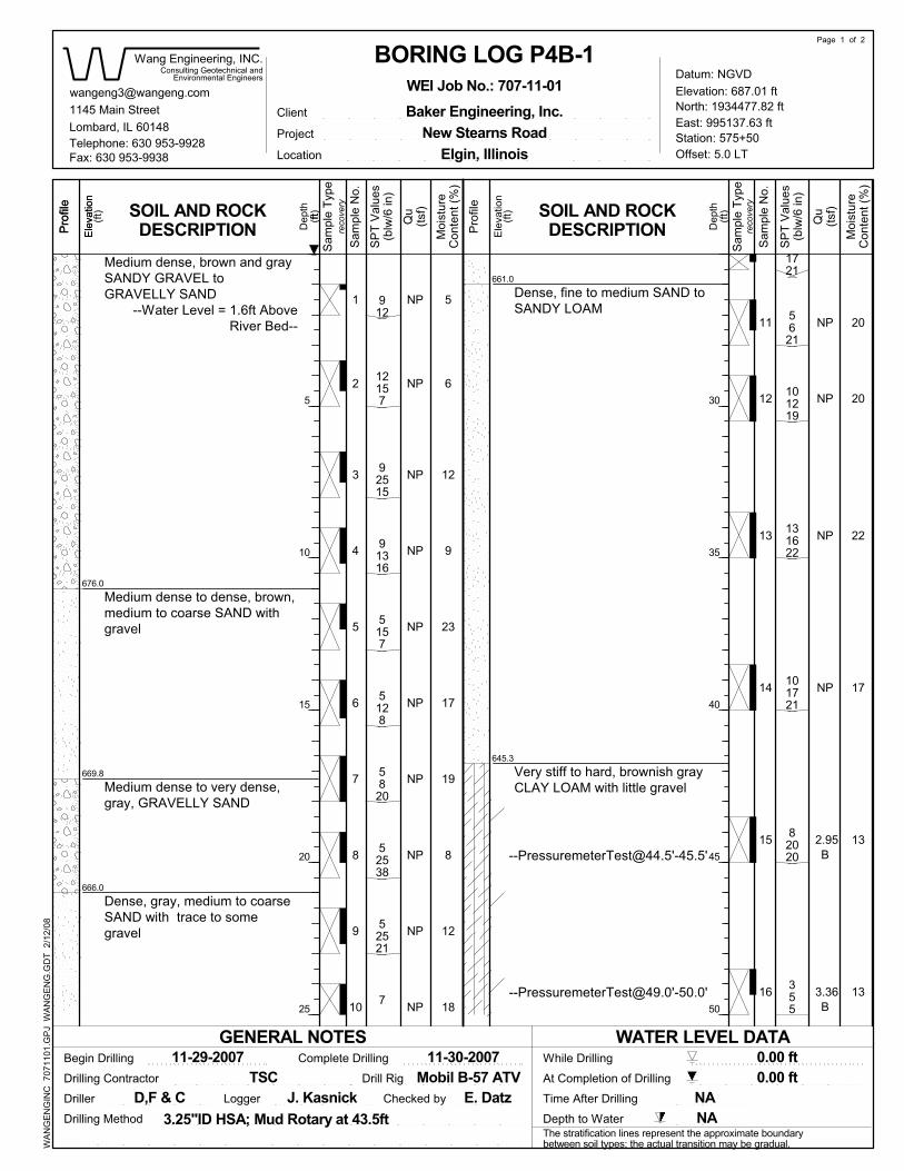
4NP
NP
2.95B
3.36B
1
NP
3
NP
5
6
7
8
9
2
NP
NPNP
13NP
NP
NP
NP
NP
NP
NP
101721
82020
355
11 5621
5157
14
15
16
912
12157
131622
91316
101219
5128
5820
52538
52521
7
1721
92515
20
12
9
23
17
19
8
669.8
18
20
22
17
13
13
12
6
5
666.0
676.0
12
[email protected]'-45.5'
661.0
645.3
Medium dense, brown and graySANDY GRAVEL toGRAVELLY SAND
--Water Level = 1.6ft AboveRiver Bed--
Medium dense to dense, brown,medium to coarse SAND withgravel
Medium dense to very dense,gray, GRAVELLY SAND
Dense, gray, medium to coarseSAND with trace to somegravel
Very stiff to hard, brownish grayCLAY LOAM with little gravel
[email protected]'-50.0'
Dense, fine to medium SAND toSANDY LOAM
At Completion of Drilling
10
Sam
ple
Type
Page 1 of 2
Qu
NA0.00 ft
NAE. Datz
Moi
stur
e
ftS
ampl
e Ty
pe
(ft)
J. Kasnick
(ft)
WEI Job No.: 707-11-01
BORING LOG P4B-1
LoggerD,F & C
WA
NG
EN
GIN
C 7
0711
01.G
PJ
WA
NG
EN
G.G
DT
2/1
2/08
(ft)
Qu
Lombard, IL 60148
Dep
th
Moi
stur
e
Dep
th
0.00 ftTSC
Con
tent
(%)
11-30-2007
Client
(tsf)
Pro
file
(ft)
East: 995137.63 ft
Drilling Contractor
While DrillingGENERAL NOTES
Ele
vatio
n
Time After Drilling
Station: 575+50
Begin Drilling
SOIL AND ROCKDESCRIPTION (ts
f)
Con
tent
(%)
Baker Engineering, Inc.
Drilling Method
1145 Main Street
Driller
Consulting Geotechnical andP
rofil
e
North: 1934477.82 ft
Mobil B-57 ATV
(blw
/6 in
)
Project
Elevation: 687.01 ft
(blw
/6 in
)5
10
15
20
25
Fax: 630 953-9938
Ele
vatio
n
Offset: 5.0 LTTelephone: 630 953-9928
Location
Checked by
Depth to Water
Environmental Engineers
Sam
ple
No.
Sam
ple
No.
Pro
file
The stratification lines represent the approximate boundarybetween soil types; the actual transition may be gradual.
WATER LEVEL DATA
Wang Engineering, INC.
3.25"ID HSA; Mud Rotary at 43.5ft
11-29-2007
Ele
vatio
n
SP
T V
alue
s
recovery
SP
T V
alue
s
Drill Rig
recovery SOIL AND ROCK
DESCRIPTION
Complete Drilling
Elgin, IllinoisNew Stearns Road
Datum: NGVD
30
35
40
45
50

Checked by
LocationTelephone: 630 953-9928
Offset: 5.0 LT
(blw
/6 in
)
Fax: 630 953-9938
Pro
file
Environmental Engineers
Sam
ple
No.
55
60
65
70
75
100/6"
Boring terminated at 74.00 ft
Project
(blw
/6 in
)
Mobil B-57 ATV
North: 1934477.82 ft
Pro
file
Begin Drilling
Driller
Depth to Water
71424
Baker Engineering, Inc.
Con
tent
(%)
(tsf)
1145 Main Street
Consulting Geotechnical and
Sam
ple
No.
WA
NG
EN
GIN
C 7
0711
01.G
PJ
WA
NG
EN
G.G
DT
2/1
2/08
8
Very dense, gray GRAVELLYSAND
Hard, gray CLAY LOAM
Dense, brown and gray, mediumto coarse SAND
[email protected]'-65.0'
[email protected]'-60.0'
[email protected]'-55.0'
613.0
615.0
182024
620.3
12
11
11
13
616.8
2.62B
477
21
20
19
18
17
NP
> 4.50P
10.09B
102433
9.10S
Elevation: 687.01 ft
Dep
th
0.00 ft
Time After Drilling
Ele
vatio
n
Qu
Pro
file
Station: 575+50
While Drilling
Drilling Contractor
East: 995137.63 ft
(ft)
(ft)
Drilling Method
ft
Sam
ple
Type
ClientLombard, IL 60148
Con
tent
(%)
TSC
(ft)
(tsf)
Moi
stur
e
Dep
th
11-30-2007
Ele
vatio
recovery
New Stearns Road
recovery
WATER LEVEL DATA
Wang Engineering, INC.
11-29-2007
Datum: NGVD
SP
T V
alue
s
SP
T V
alue
s
The stratification lines represent the approximate boundarybetween soil types; the actual transition may be gradual.
Drill Rig
SOIL AND ROCKDESCRIPTION
Complete Drilling
Elgin, Illinois
3.25"ID HSA; Mud Rotary at 43.5ft
SOIL AND ROCKDESCRIPTIONE
leva
tion
E. DatzNA
0.00 ftAt Completion of Drilling
Moi
stur
e
Qu
Page 2 of 2
J. KasnickD,F & C Logger
BORING LOG P4B-1WEI Job No.: 707-11-01
(ft)
Sam
ple
Type
GENERAL NOTES
NA

4 0.82B
0.33B
NP
NP
1 NP
3
1.64B
5
6
7
8
9
10
2
NP
NPB
NP
NP
NP
NP
1.39B
2.95B
3.94B
NP
101213
152228
797
4611
14
15
16
71312
6610
355
468
345
6911
5712
5810
71113
5711
567
12
368
10
3
5
3
13
13
2
21
32
13
12
10
13
7
714.7
17
4
690.9
714.3
Soft to medium stiff, brownCLAY LOAM
13
683.6
673.3
14-inch thick black SILTYLOAM
--TOPSOIL--Hard, brown SANDY CLAYMedium dense, brownGRAVELLY SAND to SANDYGRAVEL
Medium dense, brown to gray,fine SAND, little gravel
Medium dense to dense, grayGRAVELLY SAND
699.6
Stiff to very stiff, gray CLAY,with gravel
11
Page 1 of 2
Sam
ple
Type
Qu
Moi
stur
e
At Completion of Drilling N/A
NAE. Datz
[email protected] WEI Job No.: 707-11-01
Sam
ple
Type
(ft)
GENERAL NOTES
J. Kasnick
12-13-2007
NA
BORING LOG S1B-1
ft
LoggerF & C
(ft)
WA
NG
EN
GIN
C 7
0711
01.G
PJ
WA
NG
EN
G.G
DT
2/1
2/08
Qu
Lombard, IL 60148
Dep
th
26.66 ft
(tsf)
(ft)
TSC
Con
tent
(%)
Client
Moi
stur
e
(ft)
East: 994504.83 ft
Drilling Contractor
While Drilling
Dep
th
Station: 566+18
Pro
file
Ele
vatio
n
Time After Drilling
Depth to Water
Elevation: 715.83 ft
Consulting Geotechnical and
Sam
ple
No.
Sam
ple
No.
SOIL AND ROCKDESCRIPTION
3.25"ID HSA
Project
Elgin, Illinois
Checked by
Complete Drilling
Environmental Engineers
Driller
(tsf)
Con
tent
(%)
Baker Engineering, Inc.
Drilling Method
1145 Main Street
Begin Drilling
Pro
file
North: 1934488.61 ft
CME-55 ATV
(blw
/6 in
)
Drill Rig
New Stearns Road
WATER LEVEL DATA
Location
5
10
15
20
25
recoverySOIL AND ROCK
DESCRIPTIONrecovery
Datum: NGVD
30
35
40
45
50
(blw
/6 in
)
Ele
vatio
n
Telephone: 630 953-9928
The stratification lines represent the approximate boundarybetween soil types; the actual transition may be gradual.
SP
T V
alue
s
Offset: 18.0 RT
SP
T V
alue
s
Ele
vatio
n
12-13-2007
Fax: 630 953-9938
Pro
file
Wang Engineering, INC.
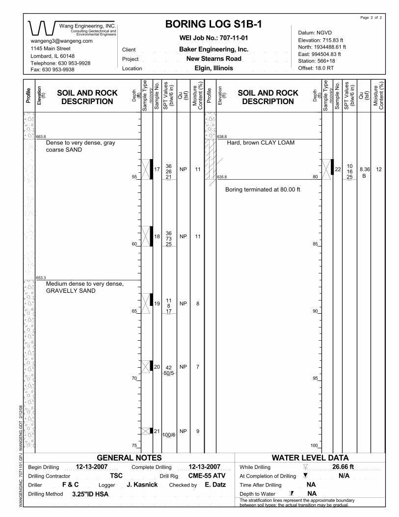
LocationTelephone: 630 953-9928
Offset: 18.0 RT
(blw
/6 in
)
Fax: 630 953-9938
Pro
file
11817
55
60
65
70
75
Environmental Engineers
101625
100/6
Project
(blw
/6 in
)
CME-55 ATV
North: 1934488.61 ft
Pro
file
Begin Drilling
Driller Checked by
Drilling Method Depth to Water
Con
tent
(%)
Boring terminated at 80.00 ft
1145 Main Street
Consulting Geotechnical and
Sam
ple
No.
Sam
ple
No.
367325
9
Hard, brown CLAY LOAM
Medium dense to very dense,GRAVELLY SAND
Dense to very dense, graycoarse SAND
635.8
638.8
653.3
4250/5
12
7
8
11
11
663.8
NP362621
22
21
20
19
18
17 8.36B
NP
NP
NP
Baker Engineering, Inc.
NP
Ele
vatio
n
Lombard, IL 60148
Dep
th
26.66 ft
(tsf)
(ft)
Elevation: 715.83 ft
Moi
stur
e
Pro
file
Station: 566+18
While Drilling
Drilling Contractor
East: 994504.83 ft
(ft)
80
85
90
95
100
WA
NG
EN
GIN
C 7
0711
01.G
PJ
WA
NG
EN
G.G
DT
2/1
2/08
ft
Sam
ple
Type
Dep
th
12-13-2007
Client
Con
tent
(%)
TSC
(ft)
(tsf)
Time After Drilling
The stratification lines represent the approximate boundarybetween soil types; the actual transition may be gradual.
3.25"ID HSA
Datum: NGVD
SP
T V
alue
s
Complete Drilling
Elgin, Illinois
SP
T V
alue
s
SOIL AND ROCKDESCRIPTION
12-13-2007
recovery
New Stearns Road
recovery
WATER LEVEL DATA
Wang Engineering, INC.
Ele
vatio
n
F & C
Qu
E. DatzNA
N/AAt Completion of Drilling
Moi
stur
e
Qu
Page 2 of 2
(ft)
NADrill Rig
Logger
Ele
vatio
n
BORING LOG S1B-1WEI Job No.: 707-11-01
SOIL AND ROCKDESCRIPTION
GENERAL NOTES
Sam
ple
Type
J. Kasnick


Geotechnical • Construction • Environmental Quality Engineering Services Since 1982
APPENDIX B

0
10
20
30
40
50
60
0 20 40 60 80 100
P3B-1
P3B-1
P3B-1
P3B-1
P4B-1
P4B-1
P4B-1
P4B-1
P4B-1
P4B-1
P4B-1
S1B-1
S1B-1
S1B-1
S1B-1
S1B-1
S1B-1
LL PL PI
ATTERBERG LIMITS' RESULTS
8.5
16.0
56.0
71.0
3.5
9.0
14.0
21.5
33.5
43.5
58.5
6.0
13.5
21.0
33.5
48.5
58.5
Specimen Identification
Fines Classification
CL-ML
PLASTICITY
INDEX
LIQUID LIMIT
ML
CL
MH
CH
95
25
67
65
6
6
11
8
30
70
72
7
4
83
55
12
7
28
22
24
20
NP
NP
NP
NP
NP
23
26
NP
NP
30
17
NP
NP
16
13
12
11
NP
NP
NP
NP
NP
12
11
NP
NP
15
12
NP
NP
12
9
12
9
NP
NP
NP
NP
NP
11
15
NP
NP
15
5
NP
NP
LEAN CLAY(CL)
CLAYEY SAND with GRAVEL(SC)
SANDY LEAN CLAY(CL)
SANDY LEAN CLAY(CL)
POORLY GRADED GRAVEL with SILT and SAND(GP-GM)
POORLY GRADED SAND with SILT and GRAVEL(SP-SM)
WELL-GRADED SAND with SILT and GRAVEL(SW-SM)
POORLY GRADED SAND with SILT and GRAVEL(SP-SM)
SILTY SAND(SM)
SANDY LEAN CLAY(CL)
LEAN CLAY with SAND(CL)
POORLY GRADED SAND with SILT(SP-SM)
WELL-GRADED GRAVEL with SAND(GW)
LEAN CLAY with SAND(CL)
SANDY SILTY CLAY(CL-ML)
WELL-GRADED SAND with SILT and GRAVEL(SW-SM)
POORLY GRADED SAND with SILT(SP-SM)
Wang Engineering
Telephone:Fax:
Project: New Stearns Road over Fox River
Location: Sec. 2 and 3, T 40 N, R 8 E of Geneva Quadrangle
Number: 707-11-01
WE
I_A
TTE
RB
ER
G_L
IMIT
S 7
0711
01.G
PJ
US
_LA
B.G
DT
10/
23/0
8

0
5
10
15
20
25
30
35
40
45
50
55
60
65
70
75
80
85
90
95
100
0.0010.010.1110100
810 14
Specimen Identification
Specimen Identification
8.516.056.071.03.5
16 20 30 40 501.5
D30 D10
41 3/4
8.516.056.071.03.5
Cu
PI Cc
GRAIN SIZE DISTRIBUTION
1/23/8 3
%Gravel %Sand %Silt %Clay
P3B-1P3B-1P3B-1P3B-1P4B-1
100 1403 2
COBBLES
4
P3B-1P3B-1P3B-1P3B-1P4B-1
LL PL
1116.35
42.66
SANDSILT AND CLAY
6.40
0.59
60
fine
HYDROMETERU.S. SIEVE OPENING IN INCHES U.S. SIEVE NUMBERS
129129
NP
16131211NP
28222420NP
6.4
5.324.024.920.5
0.0163.8650.0480.07
7.966
PE
RC
EN
T FI
NE
R B
Y W
EIG
HT
6
GRAIN SIZE IN MILLIMETERS
21919
12.538.1
0.0030.2930.0040.0120.936
0.003
0.187
200
D100 D60
6
coarseGRAVEL
Silty Clay LoamGravelly Loam
Clay LoamGravelly Silty Loam
Gravelly Loam
0.051.68.515.160.8
69.916.943.149.2
24.87.523.515.2
IDH Classification
Wang Engineering
Telephone:Fax:
Project: New Stearns Road over Fox River
Location: Sec. 2 and 3, T 40 N, R 8 E of Geneva Quadrangle
Number: 707-11-01
WE
I_G
RA
IN_S
IZE
_ID
H 7
0711
01.G
PJ
US
_LA
B.G
DT
10/
23/0
8

0
5
10
15
20
25
30
35
40
45
50
55
60
65
70
75
80
85
90
95
100
0.0010.010.1110100
810 14
Specimen Identification
Specimen Identification
9.014.021.533.543.5
16 20 30 40 501.5
D30 D10
41 3/4
9.014.021.533.543.5
Cu
PI Cc
GRAIN SIZE DISTRIBUTION
1/23/8 3
%Gravel %Sand %Silt %Clay
P4B-1P4B-1P4B-1P4B-1P4B-1
100 1403 2
COBBLES
4
P4B-1P4B-1P4B-1P4B-1P4B-1
LL PL15.7523.0118.41
SANDSILT AND CLAY
0.581.160.48
60
fine
HYDROMETERU.S. SIEVE OPENING IN INCHES U.S. SIEVE NUMBERS
NPNPNPNP11
NPNPNPNP12
NPNPNPNP23
6.011.37.829.8
24.5
2.8751.4
1.8660.1890.042
PE
RC
EN
T FI
NE
R B
Y W
EIG
HT
6
GRAIN SIZE IN MILLIMETERS
38.119
38.1219
0.550.3140.3010.0750.003
0.183
0.101
200
D100 D60
6
coarseGRAVEL
Gravelly LoamGravelly LoamGravelly Loam
LoamClay Loam
44.933.039.00.05.9 43.7 25.9
IDH Classification
Wang Engineering
Telephone:Fax:
Project: New Stearns Road over Fox River
Location: Sec. 2 and 3, T 40 N, R 8 E of Geneva Quadrangle
Number: 707-11-01
WE
I_G
RA
IN_S
IZE
_ID
H 7
0711
01.G
PJ
US
_LA
B.G
DT
10/
23/0
8

0
5
10
15
20
25
30
35
40
45
50
55
60
65
70
75
80
85
90
95
100
0.0010.010.1110100
810 14
Specimen Identification
Specimen Identification
58.56.0
13.521.033.5
16 20 30 40 501.5
D30 D10
41 3/4
58.56.0
13.521.033.5
Cu
PI Cc
GRAIN SIZE DISTRIBUTION
1/23/8 3
%Gravel %Sand %Silt %Clay
P4B-1S1B-1S1B-1S1B-1S1B-1
100 1403 2
COBBLES
4
P4B-1S1B-1S1B-1S1B-1S1B-1
LL PL
6.4921.83
SANDSILT AND CLAY
0.801.07
60
fine
HYDROMETERU.S. SIEVE OPENING IN INCHES U.S. SIEVE NUMBERS
15NPNP155
11NPNP1512
26NPNP3017
6.83.9
24.0
14.640.2
0.0381.0888.15
0.0070.099
PE
RC
EN
T FI
NE
R B
Y W
EIG
HT
6
GRAIN SIZE IN MILLIMETERS
12.525
38.19.512.7
0.0030.3821.808
0.01
0.1670.373
200
D100 D60
6
coarseGRAVEL
Clay LoamGravelly LoamGravelly Loam
LoamLoam
4.522.468.72.64.8
45.4 26.0
IDH Classification
Wang Engineering
Telephone:Fax:
Project: New Stearns Road over Fox River
Location: Sec. 2 and 3, T 40 N, R 8 E of Geneva Quadrangle
Number: 707-11-01
WE
I_G
RA
IN_S
IZE
_ID
H 7
0711
01.G
PJ
US
_LA
B.G
DT
10/
23/0
8

0
5
10
15
20
25
30
35
40
45
50
55
60
65
70
75
80
85
90
95
100
0.0010.010.1110100
810 14
Specimen Identification
Specimen Identification
48.558.5
16 20 30 40 501.5
D30 D10
41 3/4
48.558.5
Cu
PI Cc
GRAIN SIZE DISTRIBUTION
1/23/8 3
%Gravel %Sand %Silt %Clay
S1B-1S1B-1
100 1403 2
COBBLES
4
S1B-1S1B-1
LL PL48.915.15
SANDSILT AND CLAY
2.101.53
60
fine
HYDROMETERU.S. SIEVE OPENING IN INCHES U.S. SIEVE NUMBERS
NPNP
NPNP
NPNP
12.07.0
2.1660.965
PE
RC
EN
T FI
NE
R B
Y W
EIG
HT
6
GRAIN SIZE IN MILLIMETERS
38.19.5
0.4490.526 0.187
200
D100 D60
6
coarseGRAVEL
Gravelly LoamLoam
41.14.0
IDH Classification
Wang Engineering
Telephone:Fax:
Project: New Stearns Road over Fox River
Location: Sec. 2 and 3, T 40 N, R 8 E of Geneva Quadrangle
Number: 707-11-01
WE
I_G
RA
IN_S
IZE
_ID
H 7
0711
01.G
PJ
US
_LA
B.G
DT
10/
23/0
8

Geotechnical • Construction • Environmental Quality Engineering Services Since 1982
APPENDIX C


Geotechnical • Construction • Environmental Quality Engineering Services Since 1982
APPENDIX D