Embed Size (px)
Citation preview

Barlow Solar Energy Centre Project Description Report
FINAL REPORT
Prepared for: Barlow Energy Centre Limited Partnership 53 Jarvis Street, Suite 300 Toronto, Ontario M5C 2H2
Prepared by: Stantec Consulting Ltd. 300W-675 Cochrane Drive Markham, Ontario L3R 0B8
File No. 160950879 June 12, 2017

Sign-off Sheet
This document entitled Barlow Solar Energy Centre Project Description Report was prepared by Stantec Consulting Ltd. (“Stantec”) for the account of Barlow Energy Centre Limited Partnership (the “Client”). In connection with the Client’s application for a Renewable Energy Approval, this document may be reviewed and used by the following entities in the normal course of their review and approval process: (a) the Ministry of the Environment and Climate Change; (b) the Ministry of Natural Resources and Forestry; (c) the Ministry of Tourism, Culture and Sport; and (d) the Environmental Review Tribunal. Except as set forth in (a) through (d) above, any reliance on this document by any third party is strictly prohibited. The material in it reflects Stantec’s professional judgment in light of the scope, schedule and other limitations stated in the document and in the contract between Stantec and the Client. The opinions in the document are based on conditions and information existing at the time the document was published and do not take into account any subsequent changes. In preparing the document, Stantec did not verify information supplied to it by others, unless otherwise stated therein. Any use which a third party makes of this document is the responsibility of such third party. Such third party agrees that Stantec shall not be responsible for costs or damages of any kind, if any, suffered by it or any other third party as a result of decisions made or actions taken based on this document.
Prepared by: Mark Iamarino, MCIP, RPP, Environmental Planner
Reviewed by:
(signature) Tanya Turk, M.Sc., P.Ag. Project Manager
Approved by
(signature) Rob Nadolny, B.Sc. Hons. Principal – Power & Energy

BARLOW SOLAR ENERGY CENTRE PROJECT DESCRIPTION REPORT
Table of Contents
ABBREVIATIONS ............................................................................................................................ I
1.0 INTRODUCTION ............................................................................................................. 1.1 1.1 REPORT REQUIREMENTS ................................................................................................... 1.1
2.0 CONTACTS .................................................................................................................... 2.1
3.0 AUTHORIZATIONS POTENTIALLY REQUIRED ................................................................. 3.1 3.1 PROVINCIAL AUTHORIZATIONS ....................................................................................... 3.1 3.2 MUNICIPAL ......................................................................................................................... 3.2 3.3 FEDERAL INVOLVEMENT ................................................................................................... 3.3
4.0 PROJECT INFORMATION ............................................................................................... 4.1 4.1 PROJECT LOCATION ........................................................................................................ 4.1 4.2 ENERGY SOURCES ............................................................................................................ 4.1 4.3 PROJECT COMPONENTS ................................................................................................. 4.1
4.3.1 Solar Panels and Racking ............................................................................. 4.1 4.3.2 Access Roads ................................................................................................. 4.2 4.3.3 Inverters and Inverter Step-Up Transformers .............................................. 4.2 4.3.4 Substation ........................................................................................................ 4.2 4.3.5 Collector System and Connection Line ..................................................... 4.3 4.3.6 Buildings and Structures ................................................................................ 4.3 4.3.7 Perimeter Fencing .......................................................................................... 4.3 4.3.8 Construction Staging & Temporary Storage Areas .................................. 4.3
4.4 RENEWABLE ENERGY GENERATION FACILITY CLASS ................................................... 4.4 4.5 PROJECT ACTIVITIES .......................................................................................................... 4.4 4.6 NAMEPLATE CAPACITY .................................................................................................... 4.5 4.7 LEGAL DESCRIPTION & OWNERSHIP OF LAND ............................................................. 4.5 4.8 PROJECT SCHEDULE ......................................................................................................... 4.5
5.0 DESCRIPTION OF POTENTIAL ENVIRONMENTAL EFFECTS ............................................ 5.1 5.1 METHODOLOGY ............................................................................................................... 5.1 5.2 OVERVIEW OF KEY RESULTS ............................................................................................. 5.2
5.2.1 General Design and Siting Considerations ................................................ 5.2 5.2.2 Key Net Environmental Effects of the Project ........................................... 5.2
6.0 REFERENCES................................................................................................................... 6.1
BARLOW SOLAR ENERGY CENTRE PROJECT DESCRIPTION REPORT
LIST OF TABLES Table 1.1: Project Description Report Requirements (as per O. Reg. 359/09 –
Table 1) ..................................................................................................................... 1.2 Table 3.1: Key Provincial Permits and Authorizations .......................................................... 3.1 Table 3.2: Key Municipal Permits and Authorizations .......................................................... 3.2 Table 3.3: Key Federal Permits and Authorizations .............................................................. 3.3 Table 4.1: Key Project Activities .............................................................................................. 4.4 Table 4.2: Project Schedule Overview ................................................................................... 4.5
LIST OF APPENDICES
APPENDIX A: FIGURES Figure 1: Project Location and Project Layout Figure 2: Site Plan: Conceptual Project Component Layout Figure 3: Socio-Economic Features Figure 4: Natural Features and Water Bodies
APPENDIX B: SUMMARY OF POTENTIAL ENVIRONMENTAL EFFECTS, PERFORMANCE OBJECTIVES, MITIGATION MEASURES, AND CONTINGENCY MEASURES (CONSTRUCTION & OPERATION)
Table B.1: Summary of the Potential Environmental Effects, Performance Objectives, Mitigation Measures, and Contingency Measures for the Construction Stage of the Project
Table B.2: Summary of the Potential Environmental Effects, Performance Objectives, Mitigation Measures, and Contingency Measures for the Operational Stage of the Project.

BARLOW SOLAR ENERGY CENTRE PROJECT DESCRIPTION REPORT
cn \\cd1215-f01\work_group\01609\active\160950879\planning\report\project_description report\rpt_160950879_barlow_pdr_20170612_fin.docx i
Abbreviations
AC alternating current
ANSI Area of Natural and Scientific Interest
COD Commercial Operation Date
DC direct current
DFO Fisheries and Oceans Canada
EIS Environmental Impact Study
Hydro One Hydro One Networks Inc.
km kilometre(s)
kV kilovolt(s)
LRP Large Renewable Procurement
m metre(s)
MBCA Migratory Birds Convention Act
mm millimetre(s)
MNR Ministry of Natural Resources (now Ministry of Natural Resources and Forestry)
MNRF Ministry of Natural Resources and Forestry (formerly Ministry of Natural Resources)
MOE Ministry of the Environment (now Ministry of the Environment and Climate Change)
MOECC Ministry of the Environment and Climate Change (formerly Ministry of Environment)
MTCS Ministry of Tourism, Culture and Sport
MWac megawatt alternating current
O. Reg. Ontario Regulation

BARLOW SOLAR ENERGY CENTRE PROJECT DESCRIPTION REPORT
ii cn \\cd1215-f01\work_group\01609\active\160950879\planning\report\project_description report\rpt_160950879_barlow_pdr_20170612_fin.docx
OEB Ontario Energy Board
PDR Project Description Report
PSW Provincially Significant Wetland
PV photovoltaic
REA Renewable Energy Approval
REA Checklist REA Checklist: Consideration of Potential for Heritage Resources
RRCA Raisin Region Conservation Authority
SARA Species at Risk Act
SCADA supervisory control and data acquisition
Stantec Stantec Consulting Ltd.
SWH Significant Wildlife Habitat
the Project Barlow Solar Energy Centre
the Proponent Barlow Energy Centre Limited Partnership
W watt(s)

BARLOW SOLAR ENERGY CENTRE PROJECT DESCRIPTION REPORT
Introduction June 12, 2017
cn \\cd1215-f01\work_group\01609\active\160950879\planning\report\project_description report\rpt_160950879_barlow_pdr_20170612_fin.docx 1.1
1.0 INTRODUCTION
Barlow Energy Centre Limited Partnership (the Proponent), is proposing the development of a 10 megawatt alternating current (MWac) solar energy generating facility, known as the Barlow Solar Energy Centre (the Project) approximately 10 kilometres (km) west of the city of Cornwall in the Township of South Stormont, United Counties of Stormont, Dundas and Glengarry, Ontario. The Point of Common Coupling will be located adjacent to the Project Location, in the City of Cornwall, Ontario. A map showing the location of the Project is provided in Figure 1, Appendix A. The Project will require a Renewable Energy Approval (REA) as per Ontario Regulation 359/09 (O. Reg. 359/09) - under Part V.0.1 of the Environmental Protection Act (MOECC 2009, amended 2016).
The Proponent is proposing to develop, construct and operate the Project on 38 hectares (ha; 94 acres) of land in response to the Government of Ontario’s Large Renewable Procurement (LRP) initiative to promote the development of renewable electricity in the province.
The Proponent has retained Stantec to prepare a REA application, as required under O. Reg. 359/09. The proposed solar PV distribution grid connected system would be considered a Class 3 Solar Facility under O. Reg. 359/09, s. 4.
1.1 REPORT REQUIREMENTS
This Project Description Report (PDR) is one component of the REA application for the Project, and is prepared in accordance with O. Reg. 359/09, the Ministry of Natural Resources (MNR 2009) Approval and Permitting Requirements Document for Renewable Energy Projects, and the Ministry of the Environment (MOE) Technical Guide to Renewable Energy Approvals (2017). Table 1.1 summarizes the requirements of this report as specified under O. Reg. 359/09.

BARLOW SOLAR ENERGY CENTRE PROJECT DESCRIPTION REPORT
Introduction June 12, 2017
1.2 cn \\cd1215-f01\work_group\01609\active\160950879\planning\report\project_description report\rpt_160950879_barlow_pdr_20170612_fin.docx
Table 1.1: Project Description Report Requirements (as per O. Reg. 359/09 – Table 1)
Content Location within Report
Any energy sources to be used to generate electricity at the renewable energy generation facility. Section 4.2
The facilities, equipment or technology that would be used to convert the renewable energy source or any other energy source to electricity. Section 4.3
The class of the renewable energy generation facility. Section 4.4
The activities that will be engaged in as part of the renewable energy project. Section 4.5
The name plate capacity of the renewable energy generation facility. Section 4.6
The ownership of the land on which the Project Location is to be situated. Section 4.7
Any negative environmental effects that may result from engaging in the project. Section 5.0 Appendix B
An unbound, well marked, legible and reproducible map that is an appropriate size to fit on a 215 millimetre (mm) by 280 mm page, showing the Project Location and the land within 300 m of the Project Location.
Appendix A

BARLOW SOLAR ENERGY CENTRE PROJECT DESCRIPTION REPORT
Contacts June 12, 2017
cn \\cd1215-f01\work_group\01609\active\160950879\planning\report\project_description report\rpt_160950879_barlow_pdr_20170612_fin.docx 2.1
2.0 CONTACTS
Contact information for the Proponent is as follows;
Name: Kevin Campbell Title: Senior Developer Company: Barlow Energy Centre Limited Partnership Address: 53 Jarvis Street, Ste. 300, Toronto, ON M5C 2H2 Phone #: 416-216-5053 Email: [email protected] Project Website: http://www.edf-en.ca/project/barlow-solar-energy-centre
The lead consultant for preparation of the REA Application is Stantec. Stantec provides professional consulting services in planning, engineering, architecture, interior design, landscape architecture, surveying, environmental sciences, project management, and project economics for infrastructure and facilities projects. The consultant’s office and Project contact is:
Name: Tanya Turk Title: Project Manager Company: Stantec Consulting Ltd. Address: 300-675 Cochrane Drive
Markham, ON, L3R 0B8 Phone #: 905-415-6416 Email: [email protected]

BARLOW SOLAR ENERGY CENTRE PROJECT DESCRIPTION REPORT
Authorizations Potentially Required June 12, 2017
cn \\cd1215-f01\work_group\01609\active\160950879\planning\report\project_description report\rpt_160950879_barlow_pdr_20170612_fin.docx 3.1
3.0 AUTHORIZATIONS POTENTIALLY REQUIRED
The potential provincial and municipal permits, approvals, and agreements (collectively referred to as the Authorizations) which may be required for this Project are discussed below. As the Project studies progress, this information will be updated as required.
3.1 PROVINCIAL AUTHORIZATIONS
The Project must receive a REA from the MOECC. The REA application includes confirmation from the MNRF and the Ministry of Tourism, Culture and Sport (MTCS) that these ministries are satisfied with specific reports included in the application. In addition, at the provincial level there are multiple authorizations that may be required to facilitate the development of the Project. Their ultimate applicability will be determined during the REA process and based upon the Project’s detailed design. Table 3.1 lists key permits and authorizations that may be required in addition to the REA.
Table3. 3.1: Key Provincial Permits and Authorizations
Administering Agency Key Permit / Authorization Rationale
Ministry of Transportation Change of Access and Heavy/Oversize Load Transportation Permit
To maintain compliance with provincial highway traffic and road safety regulations for transport of project components to the site.
MNRF Approvals under the Endangered Species Act, 2007 (ESA)
Based on work completed during the REA process, and consultation with the MNRF, application for a permit is not required.
Approval under the Fish and Wildlife Conservation Act, 1997
In-water work to install the temporary and permanent culverts along Cornwall Centre Road will require work area isolation and a fish removal. Therefore, it will be necessary to apply for a License to Collect Fish for Scientific Purposes (post-REA), which is issued under the Fish and Wildlife Conservation Act.
Raisin Region Conservation Authority (RRCA)
Development, Interference with Wetlands, and Alterations to Shorelines and Watercourses Permit
Consultation by the Proponent with the RRCA will continue, to determine if the watercourses historically mapped within the Project Location will require permitting for work within a floodplain.
Electrical Safety Authority Electrical Safety Code Certification
Electrical systems and connections will require inspection/Authorization.
Ministry of Labour Notice of Project Notify the Ministry of Labour before construction begins.

BARLOW SOLAR ENERGY CENTRE PROJECT DESCRIPTION REPORT
Authorizations Potentially Required June 12, 2017
3.2 cn \\cd1215-f01\work_group\01609\active\160950879\planning\report\project_description report\rpt_160950879_barlow_pdr_20170612_fin.docx
Table3. 3.1: Key Provincial Permits and Authorizations
Administering Agency Key Permit / Authorization Rationale
Ontario Energy Board (OEB)
Generator license A license will be needed from the OEB in order to generate electricity.
Hydro One Networks Inc. (Hydro One)
Connection Impact Assessment (CIA)
Technical documentation submitted for review and comment by Hydro One to maintain technical compliance with the Distributed Generation Technical Interconnection Requirements. Upgrades and changes to the utility system will be identified by Hydro One as part of this submission.
Connection Cost Agreement Recovery of costs to Hydro One of changes to allow connection based on findings from the Connection Impact Assessment.
Confirmation of Verification Evidence Report (COVER)
Document to ensure that Project is designed with the required protections as identified in the CIA, and verified to function as designed.
Distribution Connection Agreement (DCA)
Legal agreement that outlines the project characteristics and operating procedures that are to be maintained and adhered to while Project is connected to Hydro One distribution system.
3.2 MUNICIPAL
The Proponent has consulted with the Township of South Stormont and the City of Cornwall, and identified key permits and authorizations that may be required to proceed with the Project. These are listed in Table 3.2.
Table 3.2: Key Municipal Permits and Authorizations
Key Permit / Authorization Rationale
Building Permit May be required for compliance with building codes.
Entrance Permit Required if an entrance from a municipal road is to be constructed.
Road Use Agreement May be required for use of roads to construct/operate the facility and for works in municipal road allowances.

BARLOW SOLAR ENERGY CENTRE PROJECT DESCRIPTION REPORT
Authorizations Potentially Required June 12, 2017
cn \\cd1215-f01\work_group\01609\active\160950879\planning\report\project_description report\rpt_160950879_barlow_pdr_20170612_fin.docx 3.3
3.3 FEDERAL INVOLVEMENT
A Federal Environmental Assessment report is not expected to be required for the Project, as the Project is not listed in the Regulations Designating Physical Activities under the Canadian Environmental Assessment Act. Table 3.3 lists key federal permits and authorizations that may be required to facilitate construction of the Project. These requirements will be determined once conceptual plans are complete and additional data has been collected. Table 3.3: Key Federal Permits and Authorizations
Administering Agency Key Permit / Authorization Rationale
Environment Canada Clearing of vegetation under the Migratory Bird Convention Act (MBCA) (1994)
No permit is necessary; however, precautions need to be made so that no breeding birds or their nests are harmed or destroyed during the bird nesting season. Nest sweeps will be required at a maximum of 7 days prior to vegetation removal during the bird nesting season (April 1 to August 31), as per the MBCA.
Fisheries and Oceans Canada (DFO)
Review and authorization under Section 35 of the Fisheries Act (1985)
Works associated with the Project will require assessment to determine if a Fisheries Act review is required. A Self-Assessment should be completed for all work near water, to document potential impacts and mitigation measures with respect to water bodies within 120 m of the Project Location. The impact assessment should be submitted to DFO for review, as the installation of culverts (temporary or permanent) is an activity that does not meet the exclusion criteria on DFO’s website. It is anticipated that potential impacts associated with other Project activities presented in the Water Assessment and Water Body Report can be mitigated.
Permitting under Section 32 of the Species at Risk Act (SARA) (2002)
As there are no federally listed aquatic species at risk in the Project Location, a SARA permit for aquatic species at risk is not required.

BARLOW SOLAR ENERGY CENTRE PROJECT DESCRIPTION REPORT
Project Information June 12, 2017
cn \\cd1215-f01\work_group\01609\active\160950879\planning\report\project_description report\rpt_160950879_barlow_pdr_20170612_fin.docx 4.1
4.0 PROJECT INFORMATION
The following section outlines the location, energy sources and components pertaining to the proposed Project, as well as details on the Project schedule, activities, nameplate capacity and land ownership.
4.1 PROJECT LOCATION
The Project is located in the Township of South Stormont within the United Counties of Stormont, Dundas and Glengarry and the site access, part of the Connection Line, and Point of Common Coupling (i.e., point at which Hydro One will connect to the Project) are located in the City of Cornwall. A Trans Northern Pipeline Inc. pipeline and Hydro One transmission line bisect the Project. The Point of Common Coupling will be located within the Project Location, within the road allowance of Cornwall Centre Road in the City of Cornwall. Maps showing the Project Location are provided in Appendix A. A 300 m buffer surrounding the Project Location has been applied to Figures 1-4 in Appendix A, as outlined in O. Reg. 359/09 and the MOECC’s “Technical Guide to Renewable Energy Approvals” (2017). This buffer has been applied for visual purposes only, and does not create any new obligations or change the land use for associated neighboring lands outside the Project Location.
The term “Project Location” is defined by O. Reg. 359/09 as:
“a part of land and all or part of any building or structure in, on or over which a person is engaging in or proposes to engage in the project and any air space in which a person is engaging in or proposes to engage in the project” (MOECC 2009, amended 2016).
The current Project Location generally consists of the parcel boundary on which the solar facility will be located and the land associated with the connection line and Point of Common Coupling. The Project Location has been refined to optimize the Project and minimize environmental effects, as determined following field studies and Project layout design.
4.2 ENERGY SOURCES
The proposed Project is a solar facility that would utilize sunlight as a source of energy.
4.3 PROJECT COMPONENTS
4.3.1 Solar Panels and Racking
The Project will include the installation of approximately 30,000 to 50,000 solar panels. The exact make and model of the solar panels will be determined at a later date, but are anticipated to

BARLOW SOLAR ENERGY CENTRE PROJECT DESCRIPTION REPORT
Project Information June 12, 2017
4.2 cn \\cd1215-f01\work_group\01609\active\160950879\planning\report\project_description report\rpt_160950879_barlow_pdr_20170612_fin.docx
have a rated power of 300-420 W per panel and measure approximately 2 m long by 1 m wide. Each solar panel will be mounted on a galvanized steel and/or aluminum rack system that is positioned approximately 0.5 to 1.5 m above finished grade either at an angle between 20 and 40 degrees (fixed tilt) or with a +/- 60-degree range of motion (single axis tracking). Fixed tilt panels would be installed in rows facing south and the tracking system would be tracking east/west on a north/south axis.
4.3.2 Access Roads
Existing provincial and county roads will be used to transport project-related components, equipment and personnel to the Project Location. An existing entrance from Cornwall Centre Road is anticipated to be used for permanent access to the site and may be modified as required. A second access point may be required to facilitate construction. Gravel access roads will be constructed within the site to provide access to the facility for the duration of the Project. Section 4.3.7 provides further details on perimeter fencing.
4.3.3 Inverters and Inverter Step-Up Transformers
Four inverter step-up transformers and inverters will be located within the Project Location. The inverters will convert the direct current (DC) electricity to alternating current (AC) electricity while the inverter step-up transformers will step-up the AC voltage. In the event that no main power transformer is utilized at the substation, the inverter step-up transformers will raise the voltage to 44 kV. If the final design includes a main power transformer at the substation, the inverter step-up transformers will raise the voltage to either 27.6 kV or 34.5 kV. The electricity is then delivered to the local distribution grid level through the substation.
The specifications of the inverters and inverter step-up transformers will be determined by the Proponent during the preliminary design phase. In accordance with the specifications, the manufacturer of the inverters and inverter step-up transformers, will be selected by the Proponent or the general contractor after the preliminary design phase.
4.3.4 Substation
As identified above, a main power transformer may be required and it will be determined during the detailed design phase. The Project will require a 44kV substation comprised of circuit breakers, disconnect switches, surge arresters, station service transformer for auxiliary services, revenue metering equipment, and control building. A main power transformer may be included in the final design, in which case the substation will raise the voltage from 27.6kV or 34.5 kV to 44 kV. All of this equipment will be built in a fenced in area except the control building that may be located inside the fenced area of the substation, or may be located outside of the fenced area of the substation (but within the perimeter fence, see Section 4.3.7) to provide office space for maintenance personnel. All of this equipment is likely to be prefabricated and transported to site. The specific make of the associated electrical equipment, including the main power

BARLOW SOLAR ENERGY CENTRE PROJECT DESCRIPTION REPORT
Project Information June 12, 2017
cn \\cd1215-f01\work_group\01609\active\160950879\planning\report\project_description report\rpt_160950879_barlow_pdr_20170612_fin.docx 4.3
transformer (if applicable) will be selected by the general contractor during the detailed design phase and based on the Proponent specifications. The equipment in the substation will also provide a supervisory control and data acquisition (SCADA) system for protection, control and monitoring of the substation and the facility.
4.3.5 Collector System and Connection Line
The 1,500 volt (or below) DC electricity generated from the solar panels will be collected at combiner boxes and transported via underground or above ground cables to the inverters where it will be converted to AC electricity.
The 27.6 kV / 34.5 kV / 44 kV AC electricity from all inverter step-step up transformers will be collected via underground or above ground cables to a single substation.
Data cabling for the SCADA will also be installed in the same trenches.
A 44 kV AC connection line, approximately 57 m long, is required from the substation to the Point of Common Coupling where Hydro One will connect the Project to the 44 kV existing distribution line about 700 m to the east near the intersection of Cornwall Centre Road and Power Dam Drive in the city of Cornwall.
4.3.6 Buildings and Structures
An operations and maintenance building is not currently planned for the site. An operations and maintenance storage area will be comprised of one or two 40 foot storage containers installed adjacent to the substation and will include a locking door. The storage containers will be used to store equipment and spare parts used for planned maintenance activities.
Details on a small control building to be installed as part of the substation component are outlined in Section 4.3.4.
4.3.7 Perimeter Fencing
The facility will be surrounded with a chain link fence topped with barbed wire to prevent unauthorized access. A gate will be installed at the main entrance from Cornwall Centre Road to provide access for maintenance personnel and emergency vehicle access. A secondary access will be located west of the primary entrance for access during construction only. Perimeter fencing would be located at or within the Project Location boundary.
4.3.8 Construction Staging & Temporary Storage Areas
Construction staging areas will be used for storage of Project materials and equipment on site during construction. The construction staging areas would support construction trailers, portable toilets, waste disposal containers and pick-up areas, parking areas, equipment storage and

BARLOW SOLAR ENERGY CENTRE PROJECT DESCRIPTION REPORT
Project Information June 12, 2017
4.4 cn \\cd1215-f01\work_group\01609\active\160950879\planning\report\project_description report\rpt_160950879_barlow_pdr_20170612_fin.docx
maintenance area, truck unloading and loading area, and laydown area for materials and equipment. The construction staging area is anticipated to be located in the southwest portion of the Project Location, and may include some property owned by Infrastructure Ontario, adjacent to the Hydro One transmission corridor. Materials would be delivered directly to the Project Location for their installation, to the extent possible.
4.4 RENEWABLE ENERGY GENERATION FACILITY CLASS
The proposed solar PV distribution grid connected system would be considered a Class 3 Solar Facility under O. Reg.359/09, Section 4. This classification consists of solar facilities with nameplate capacities exceeding 10 kW that are in any location other than mounted on the roof or wall of a building.
4.5 PROJECT ACTIVITIES
A general overview of the activities during construction, operation, and decommissioning phases of the Project are provided in Table 4.1.
Table 4.1: Key Project Activities
Project Phase Activities
Construction Site grading
Access road preparation
Installation of foundations and racking
Panel installation
Installation of inverter step-up transformers, inverters, main power transformer (if applicable) and substation equipment
Installation of collector cables and connection line
Reclamation of temporary work areas
Site landscaping
Operation Preventative maintenance
Unplanned maintenance
Meter calibrations
Site/ground maintenance
Decommissioning Disconnect the connection line from the distribution grid
Removal of solar panel infrastructure
Removal of inverter step-up transformers, inverters, main power transformer (if applicable) and substation equipment
Removal of fencing, roads and site grading (dependent upon new proposed use)

BARLOW SOLAR ENERGY CENTRE PROJECT DESCRIPTION REPORT
Project Information June 12, 2017
cn \\cd1215-f01\work_group\01609\active\160950879\planning\report\project_description report\rpt_160950879_barlow_pdr_20170612_fin.docx 4.5
Table 4.1: Key Project Activities
Project Phase Activities
Excavation and removal of collector lines and foundations (up to 1 m depth below original grade) depending upon agreement with landowner
Re-establishment of tile drainage system for agricultural purposes provided that land is intended to return to agricultural production
4.6 NAMEPLATE CAPACITY
The total nameplate capacity of the solar facility is 10 MWac.
4.7 LEGAL DESCRIPTION & OWNERSHIP OF LAND
The Project would be located on part of Lots 20-21, Concession 4 in the Township of South Stormont, within the United Counties of Stormont, Dundas and Glengarry. The Project would be located on privately-owned land, leased by the Proponent for a period of 20 or more years.
4.8 PROJECT SCHEDULE
A preliminary schedule is provided in Table 4.2 and provides an overview of the key activity dates associated with the Project.
Table 4.2: Project Schedule Overview
Milestone Approximate Date
Initiate Public REA Process Spring 2016
REA technical studies Ongoing through to fall 2016
Public Meeting #1 October 2016
Draft REA Reports to Public January 2017
Final Public Meeting April 2017
Submission of REA application to the MOECC June 2017
REA Approval December 2017
Start of Construction February 2018
Commercial Operation Date (COD) December 2018
Repowering/Decommissioning 2038 (20 or more years after the COD)

BARLOW SOLAR ENERGY CENTRE PROJECT DESCRIPTION REPORT
Description of Potential Environmental Effects June 12, 2017
cn \\cd1215-f01\work_group\01609\active\160950879\planning\report\project_description report\rpt_160950879_barlow_pdr_20170612_fin.docx 5.1
5.0 DESCRIPTION OF POTENTIAL ENVIRONMENTAL EFFECTS
5.1 METHODOLOGY
The potential negative environmental effects occurring during construction, operating, and decommissioning a renewable energy facility are well understood and can be typically mitigated through well-known and accepted techniques and practices.
In order to identify potential negative environmental effects that may result from construction, operation and decommissioning of the Project, the following was applied:
• Collected information on the existing environment using available background information, consultation with stakeholders, and site investigations.
• Reviewed proposed Project activities to predict the potential interactions between the Project and environment.
• Identified potential interactions that could cause an adverse effect on the environment.
• Developed measures to avoid, mitigate, and monitor potential adverse effects.
The REA process focuses on project-specific issues and potential negative effects as per O. Reg. 359/09. Based upon a screening of the existing environment, experience gained during Project planning, and the requirements of the REA process, the following environmental features have been assessed as part of the REA application process:
• Heritage Resources
• Archaeological Resources
• Natural Heritage
• Water Bodies
• Air, Odour, Dust
• Noise
• Land Use
• Municipal Infrastructure
• Waste Management
• Public Health and Safety
The potential effects to these environmental features have been identified in the Construction Plan Report and the Design and Operations Report and mitigation measures developed as required. Detailed analysis of potential effects to some environmental features has been conducted, and is provided in the Stage 1-2 Archaeological Assessment Report, Acoustic Assessment Report, Natural Heritage Assessment & Environmental Impact Study, and Water

BARLOW SOLAR ENERGY CENTRE PROJECT DESCRIPTION REPORT
Description of Potential Environmental Effects June 12, 2017
5.2 cn \\cd1215-f01\work_group\01609\active\160950879\planning\report\project_description report\rpt_160950879_barlow_pdr_20170612_fin.docx
Assessment & Water Body Report. A summary of the potential environmental effects as a result of Project activities is provided in Appendix B. An overview of key results is provided below.
5.2 OVERVIEW OF KEY RESULTS
5.2.1 General Design and Siting Considerations
The key mitigation strategy used to address potential environmental effects from construction and operation of the facility was avoidance of significant natural and socio-economic features to the extent possible during siting of the Project.
The original Project Location encompassed the entirety of the lands leased by the Proponent and was assessed during technical studies conducted for the Natural Heritage, Water, Acoustic and Archaeological Assessments. Where necessary, the site was modified based on the findings of the technical studies, as outlined below.
The Project Location is predominantly zoned as Flood Plain (FP), but a portion in the north is zoned as Rural (RU). The Proponent is currently in consultation with the Township of South Stormont and the RRCA to determine the necessary permitting requirements and guidelines required for the Project.
Trees will be planted in early 2019 along Cornwall Centre Road on the outside of the Project Location boundary and perimeter fencing. The vegetation barrier is proposed to eventually partially mitigate the visual impact of the facility. Upon construction completion, the secondary access road will be naturalized and planted with trees along the Project Location boundary (Figure 2, Appendix A).
Site investigations completed as part of the Water Assessment & Water Body Report identified water bodies (as defined in O. Reg. 359/09) adjacent to the Project Location boundary. As a result, solar panels, inverters and transformers have been set back a minimum of 30 m from water bodies. Further details on the locations of the water bodies (as defined in O. Reg. 359/09) are located within the Water Assessment & Water Body Report.
5.2.2 Key Net Environmental Effects of the Project
Construction
Based on a review of existing information on archaeological resources in the area, and based on the completion of the MTCS REA Checklist and Stage 1 - 2 Archaeological Assessment, no known areas of heritage or archaeological resources exist within the Project area. Potential effects are limited to the finding of previously undiscovered artifacts or human remains, therefore, net effects are not anticipated.
BARLOW SOLAR ENERGY CENTRE PROJECT DESCRIPTION REPORT
Description of Potential Environmental Effects June 12, 2017
cn \\cd1215-f01\work_group\01609\active\160950879\planning\report\project_description report\rpt_160950879_barlow_pdr_20170612_fin.docx 5.3
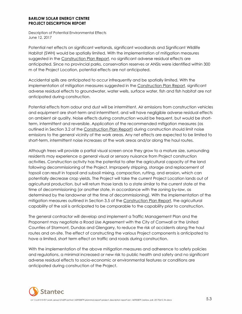
Potential net effects on significant wetlands, significant woodlands and Significant Wildlife Habitat (SWH) would be spatially limited. With the implementation of mitigation measures suggested in the Construction Plan Report, no significant adverse residual effects are anticipated. Since no provincial parks, conservation reserves or ANSIs were identified within 300 m of the Project Location, potential effects are not anticipated.
Accidental spills are anticipated to occur infrequently and be spatially limited. With the implementation of mitigation measures suggested in the Construction Plan Report, significant adverse residual effects to groundwater, water wells, surface water, fish and fish habitat are not anticipated during construction.
Potential effects from odour and dust will be intermittent. Air emissions from construction vehicles and equipment are short-term and intermittent, and will have negligible adverse residual effects on ambient air quality. Noise effects during construction would be frequent, but would be short-term, intermittent and reversible. Application of the recommended mitigation measures (as outlined in Section 3.2 of the Construction Plan Report) during construction should limit noise emissions to the general vicinity of the work areas. Any net effects are expected to be limited to short-term, intermittent noise increases at the work areas and/or along the haul routes.
Although trees will provide a partial visual screen once they grow to a mature size, surrounding residents may experience a general visual or sensory nuisance from Project construction activities. Construction activity has the potential to alter the agricultural capacity of the land following decommissioning of the Project. Improperly stripping, storage and replacement of topsoil can result in topsoil and subsoil mixing, compaction, rutting, and erosion, which can potentially decrease crop yields. The Project will take the current Project Location lands out of agricultural production, but will return those lands to a state similar to the current state at the time of decommissioning (or another state, in accordance with the zoning by-law, as determined by the landowner at the time of decommissioning). With the implementation of the mitigation measures outlined in Section 3.5 of the Construction Plan Report, the agricultural capability of the soil is anticipated to be comparable to the capability prior to construction.
The general contractor will develop and implement a Traffic Management Plan and the Proponent may negotiate a Road Use Agreement with the City of Cornwall or the United Counties of Stormont, Dundas and Glengarry, to reduce the risk of accidents along the haul routes and on-site. The effect of constructing the various Project components is anticipated to have a limited, short term effect on traffic and roads during construction.
With the implementation of the above mitigation measures and adherence to safety policies and regulations, a minimal increased or new risk to public health and safety and no significant adverse residual effects to socio-economic or environmental features or conditions are anticipated during construction of the Project.

BARLOW SOLAR ENERGY CENTRE PROJECT DESCRIPTION REPORT
Description of Potential Environmental Effects June 12, 2017
5.4 cn \\cd1215-f01\work_group\01609\active\160950879\planning\report\project_description report\rpt_160950879_barlow_pdr_20170612_fin.docx
Additional information regarding potential effects during the construction phase is provided in the Construction Plan Report.
Operation
Through completion of the MTCS REA Checklist, no built resources were identified within the Project Location and no cultural heritage landscapes or protected properties were identified in, or adjacent to, the Project Location. No significant adverse net effects on archaeological or cultural heritage resources are anticipated during operation of the Project.
During operation there may be occasional maintenance activities required, but this will occur outside of all wetland, woodland and Generalized Candidate SWH boundaries. Potential for impacts such as dust, spills are considered low from maintenance activities. Maintenance activities are expected to occur occasionally and will be short term in duration and spatially limited. With the implementation of suggested mitigation measures, no significant adverse residual effects on significant wetlands, woodlands and Generalized Candidate SWH are anticipated.
Negative environmental effects to water wells are not anticipated during operation of the Project. Water taking activities are not anticipated during operation of the Project. Water is not anticipated to be required for solar panel washing as rain water and snow should be sufficient for the cleaning of panels. If required, water for cleaning the panels will be trucked in from an off-site source. With the implementation of mitigation measures suggested in the Design & Operations Report, significant adverse residual effects to surface water, fish and fish habitat are not anticipated during operation.
Some materials, such as fuel, lubricating oils and other fluids associated with the operation phase of the Project have the potential for discharge to the natural environment through accidental spills and thus potentially infiltrate groundwater supplies. Such spills are unlikely to occur and if they do, they are anticipated to occur infrequently and be spatially limited. With the implementation of mitigation measures outlined in the Design & Operations Report, no significant adverse residual effects on groundwater or private wells are anticipated.
During the operational phase of the Project, no substantive emissions of air contaminants are expected. Minor localized air emissions would occur from the periodic use of equipment for general repairs, maintenance of panels and from personnel vehicles travelling to and from the Project Location. The Project has no facilities or equipment that will discharge contaminants or pollutants to the air (e.g., exhaust gases from emergency backup diesel generators) during operation of the Project. Sources of localized emissions during operation are considered negligible under O. Reg. 419/05. The application of the recommended mitigation measures during operations should limit air emissions to the work areas and limit the magnitude of combustion emissions (e.g., from operations and maintenance vehicles). As a result, any adverse net effects to air quality from air emissions during operation of the Project are anticipated to be short-term in duration and highly localized.

BARLOW SOLAR ENERGY CENTRE PROJECT DESCRIPTION REPORT
Description of Potential Environmental Effects June 12, 2017
cn \\cd1215-f01\work_group\01609\active\160950879\planning\report\project_description report\rpt_160950879_barlow_pdr_20170612_fin.docx 5.5
Based on the results of the Acoustic Assessment, the noise levels during the Project’s predictable worst case scenario is expected to meet the MOECC criteria at applicable Points of Reception. Further details are outlined in the Acoustic Assessment Report.
Visual nuisance to the community may occur due to the presence of the facility during the operational phase of the Project. Project infrastructure is removable and, as a result, the visual impact is considered temporary and reversible.
Operation activities have the potential to alter the agricultural capacity of the land following decommissioning of the Project. Compaction of topsoil and erosion of surface soil may occur during operation and can potentially decrease crop yields. The agricultural productivity of the Project Location will be lost during construction and operation of the Project, however, the effects to the agricultural soils are expected to be temporary and spatially limited. The Project will take the current Project Location lands out of agricultural production, but will return those lands to a state similar to the current state at the time of decommissioning (or another state, in accordance with the zoning by-law, as determined by the landowner at the time of decommissioning).
With the implementation of the mitigation measures provided in the Design & Operations Report and adherence to safety policies and regulations, no significant risks to public health and safety or adverse residual effects to socio-economic or environmental features or conditions are anticipated during operation of the Project.
Additional information regarding potential effects during the operations phase is provided in the Design & Operations Report.

BARLOW SOLAR ENERGY CENTRE PROJECT DESCRIPTION REPORT
References June 12, 2017
cn \\cd1215-f01\work_group\01609\active\160950879\planning\report\project_description report\rpt_160950879_barlow_pdr_20170612_fin.docx 6.1
6.0 REFERENCES
Canadian Environmental Assessment Act (CEAA). 2012 (S.C. 2012, c. 19, s. 52).
Canadian Ministry of the Environment. 2012. Regulations Designating Physical Activities (SOR/2012-147) made under the Canadian Environmental Assessment Act, Last amended: May 2016. Available online: http://laws-lois.justice.gc.ca/eng/regulations/SOR-2012-147/. Accessed: September, 2016.
Endangered Species Act. 2007 (S.O. 2007, c. 6).
Fish and Wildlife Conservation Act. 1997 (S.O. 1997, c. 41).
Fisheries Act (R.S.C., 1985, c. F-14).
Migratory Birds Convention Act. 1994 (S.C. 1994, c. 22).
Ministry of Natural Resources (MNR). 2009. Approval and Permitting Requirements Document for Renewable Energy Projects. Available online: https://www.ontario.ca/ document/renewable-energy-project-approval-and-permit-requirements. Accessed: September, 2016.
Ontario Ministry of the Environment and Climate Change (MOECC). 2017. Technical Guide to Renewable Energy Approvals. Available online: https://www.ontario.ca/document/technical-guide-renewable-energy-approvals-0. Accessed: June, 2017.
Ontario Ministry of the Environment and Climate Change (MOE). 2009. Ontario Regulation 359/09 Renewable Energy Approvals Under Part V.0.1 of the Act under the Environmental Protection Act. Last amended: May 2016. Available online: https://www.ontario.ca/laws/regulation/090359. Accessed: September, 2016.
Species at Risk Act (S.C. 2002, c. 29).

BARLOW SOLAR ENERGY CENTRE PROJECT DESCRIPTION REPORT
APPENDIX A: FIGURES

Project Location
Client/Project
Figure No.
Title
Cardinal
Casselman
ChestervilleFinch
Iroquois
Lancaster
Maxville
Morrisburg
Winchester
Alexandria Coteau-du-LacGrande-Île
Saint-Zotique
HuntingdonCornwall Québec
Ontario
New York
!
!
!!
!!
!!
!!
!!
!!
!!
!!
!!
!!
!!
!!
!!
!!
!!
!!
!!
!!
!!
!!
!!
!
!
!
!
!
!
!
!
!
!
!
!
!
!
!
!
!
!
!
!
!
!
!
!
!
!
!
!
!
!
!
!
!
!
!
!
!
!
!
!
!
!
!
!
!
!!
!!
!!
!!
!!
!!
!!
!!
!!
!!
!!
!!
!!
!!
!!
!!
!!
!!
!!
!!
!!
!
!
!
!
!
!
!
!
!
!
!
!
!
!
!
!
!
!
!
!
!
!
!
!
!
!
!
!
!
!
!
!
!
!
!
!
!
!
!
!
!
!
!
!
!
!
!
!
!
!
!
!
!
!
!
!
!
!
!
!
!
!
!
!
!
!
!
!
!
!
!
!
!
!
! ! ! ! ! ! ! ! ! ! ! ! ! ! ! ! ! ! ! ! ! ! ! ! ! ! ! ! ! ! ! ! ! ! ! ! ! ! ! ! ! ! ! ! ! ! ! ! ! ! ! ! !! !
! ! ! ! ! ! ! ! ! !
!
!
!
!
!
!
!
!!
!!
!!
!!
!!
!!
!!
!!
!!
!!
!!
!!
!!
!!
!!
!!
!!
!!
!!
!!
!!
!!
!
!
!
!
!
!
!
!
!
!
!
!
!
!
!
!
!
!
!
!
!
!
!
!
!
!
!
!
!
!
!
!
!
!
!
!
!
!
!
!
!
!
!
!
! !
!
!
!
!
!
!
!
!
!
!
!
!
!
!
!
!
!
!
!
!
!
!
!
!
!
!
!
!
!
!
!!
!!
!!
!
!!
!
!
!
!
!
!
!
!
!
!
!
!
!
!
!
!
!
!
!
!
!
!
!
!
!
!
!
!
!
!
!
!
!
!
!
!
!
!
!
!
!
!
!
!
!
!
!
!
!
!
!
!
!
!
!
!
!
!
!
!
!
!
!
!
!
!
!
!
!
!
!
!
!
!
!
!
!
!
!
!
!
!
!
!
!
!
!
!
!
!
!
!
!
!
!
!
!
!
!
!
!
!
!
!
!
!
!
!
!
!
!
!
!
!
!
!
!
!
!
!
!
!
!
!
!
!
!
!
!
!
!
!
!
!
!
!
!
!
!
!
!
!
!
!
!
!
!
!
!
!
!
!
!
!
!
!!
!!
!
!
!
!
!
!
!
!
!
!
!
!
!
!
!
!
!
!
!
!
!
!
!
!
!
!
!
!
!
!
!
!
!
!
!
!
!
!
!
!
!
!
!
!
!
!
!
!
!
!
!
!
!
!
!
!
!
!
!
!
!
!
!
!
!
!
!
!
!
!
!
!
!
!
!
!
!
!
!
!
!
!
!
!
!
!
!
!
!
!
!
!
!
!
!
!
!
!
!
!
!
!
!
!
!
!
!
!
!
!
!
!
!
!
!
!
!
!
!
!
!
!
!
!
!
!
!
!
!
!
!
!
!
!
!
!
!
!
!
!
!
!
!
!
!
!
!
!
!
!
!
!
!
!
!
!
!
!
!
!
!
!
!
!
!
!
!
!
!
!
!
!
!
!
!
!
!
!
!
!
!
!
!
!
!
!
!
!
!
!
!
Barlow
Road
Power Dam Drive
Atchison Road
Richmond Drive
Cornwall Centre Road
Canadian National
6020
9008
1
602090059
602090078
602090077
602090061602190073
602190072
602190071
602200101
602200151
602200054
602200099
602200135
602200136
602200104
602190076602190075
602200103
602200137
602200102
602200138602200139
602200128
602200126
6021
0000
1
602200071
6021
9007
4
602190070
602190063
602200131602200129
602200133
602200134
602200061
602190131
602200065
602200062
602190065
602200063
602200066
602200056
602200064
602200057
602190067
602200058
602190077
602200100
602200059
602190066
602200060
602190069
602190064
602200055
602190068
602200140
602200141
602200144
6022
0005
3
601390310
602190078
601390239601390319
602200164
602090
060
602200154
602200112
602200111
602200109
602200115
602200143
602200142
602200145
602200146
602200165602090052
602200107
513500
513500
514000
514000
514500
514500
515000
515000
515500
515500
4987
500
4987
500
4988
000
4988
000
4988
500
4988
500
4989
000
4989
000
1
Notes
0 200 400metres
W:\a
ctive
\609
5087
9\dr
awing
\MXD
\APC
\Rep
ortFi
gure
s\PD
R\16
0950
879_
PDR_
Fig01
_Site
Loca
tion.m
xd
Rev
ised:
2017
-05-26
By: d
harve
y
($$¯
1:7,741 (At original document size of 11x17)
160950879 REVF
Disclaimer: Stantec assumes no responsibility for data supplied in electronic format. The recipient accepts full responsibility for verifying the accuracy and completeness of the data. The recipient releases Stantec, its officers, employees, consultants and agents, from any and all claims arising in any way from the content or provision of the data.
Prepared by AW on 2017-05-26Technical Review by RN on 2017-01-02
Independent Review by RN on 2017-01-02
Project Location
1. Coordinate System: NAD 1983 UTM Zone 18N2. Base features and aerial imagery produced under license with the Ontario Ministryof Natural Resources and Forestry © Queen's Printer for Ontario, 2016.3. Imagery Source: DRAPE 2014
BARLOW ENERGY CENTRE LIMITED PARTNERSHIPBARLOW SOLAR ENERGY CENTRE
United Counties ofStormont, Dundas andGlengarry
LegendProject Location300 m from Project Location
Existing / Natural FeaturesMajor RoadMinor Road
! ! Hydro One Transmission LinePipelineRailwayProperty Boundary and PIN
The Oak Ridges Moraine Conservation Plan Area, theNiagara Escarpment and the Lake Simcoewatershed are not within 300 m of the ProjectLocation.
No protected properties, heritage resources orarchaeological resources were identified within 300m of the Project Location.

Project Location
Client/Project
Figure No.
Title
Cornwall Québec
Ontario
New York
Cardinal
Casselman
ChestervilleFinch
Iroquois
Lancaster
Maxville
Morrisburg
Winchester
Alexandria Coteau-du-LacGrande-Île
Saint-Zotique
Huntingdon
!
!
!!
!!
!!
!!
!!
!!
!!
!!
!!
!!
!!
!!
!!
!!
!!
!!
!!
!!
!!
!!
!!
!!
!
!
!
!
!
!
!
!
!
!
!
!
!
!
!
!
!
!
!
!
!
!
!
!
!
!
!
!
!
!
!
!
!
!
!
!
!
!
!
!
!
!
!
!
! !
!
!!
!!
!!
!!
!!
!!
!!
!!
!!
!!
!!
!!
!!
!!
!!
!!
!!
!!
!!
!!
!!
!!
!
!
!
!
!
!
!
!
!
!
!
!
!
!
!
!
!
!
!
!
!
!
!
!
!
!
!
!
!
!
!
!
!
!
!
!
!
!
!
!
!
!
!
!
!
!
!
!!
!!
!!
!!
!!
!!
!!
!!
!!
!!
!!
!!
!!
!!
!!
!!
!
!
!
!
!
!
!
!
!
!
!
!
!
!
!
!
!
!
!
!
!
!
!
!
!
!
!
!
!
!
!
!
!
!
!
!
!
!
!
!
!
!
!
!
!
!
!
!
!
!
!
!
!
!
!
!
!
!
!
!
!
!
!
!
!
!
!
!
!
!
!
!
!
!
!
!
!
!
! ! ! ! ! ! ! ! ! ! ! ! ! ! ! ! ! ! ! ! ! ! ! ! ! ! ! ! ! ! ! ! ! ! ! ! ! ! ! ! ! ! ! ! ! ! ! ! ! ! ! ! !! !
! !! ! ! ! ! ! ! ! ! !
!
!
!
!
!
!
!
!!
!!
!!
!!
!!
!!
!!
!!
!!
!!
!!
!!
!!
!!
!!
!!
!!
!!
!!
!!
!!
!!
!!
!
!
!
!
!
!
!
!
!
!
!
!
!
!
!
!
!
!
!
!
!
!
!
!
!
!
!
!
!
!
!
!
!
!
!
!
!
!
!
!
!
!
!
!
!
!
TU
TU
TU
TU
TU
TU
TU
TU
TU
TU
TU
TU
!
!
!!
!!
!!
!!
!!
!!
!!
!!
!!
!!
!!
!!
!!
!!
!!
!!
!!
!!
!!
!!
!!
!!
!
!
!
!
!
!
!
!
!
!
!
!
!
!
!
!
!
!
!
!
!
!
!
!
!
!
!
!
!
!
!
!
!
!
!
!
!
!
!
!
!
!
!
!
!
!
!!
!
!
!
!
!
!
!
!
!
!
!
!
!
!
!
!
!
!
!
!
!
!
!
!
!
!
!
!
!
!
!
!!
!!
!
!!
!!
!
!
!
!
!
!
!
!
!
!
!
!
!
!
!
!
!
!
!
!
!
!
!
!
!
!
!
!
!
!
!
!
!
!
!
!
!
!
!
!
!
!
!
!
!
!
!
!
!
!
!
!
!
!
!
!
!
!
!
!
!
!
!
!
!
!
!
!
!
!
!
!
!
!
!
!
!
!
!
!
!
!
!
!
!
!
!
!
!
!
!
!
!
!
!
!
!
!
!
!
!
!
!
!
!
!
!
!
!
!
!
!
!
!
!
!
!
!
!
!
!
!
!
!
!
!
!
!
!
!
!
!
!
!
!
!
!
!
!
!
!
!
!
!
!
!
!
!
!
!
!
!
!
!
!
!
!
!
!
!
!!
!!
!!
!!
!!
!!
!!
!!
!!
!!
!!
!!
!!
!!
!!
!!
!!
!!
!!
!!
!!
!!
!!
!!
!!
!!
!!
!!
!!
!!
!!
!!
!!
!!
!!
!!
!
!
!
!
!
!
!
!
!
!
!
!
!
!
!
!
!
!
!
!
!
!
!
!
!
!
!
!
!
!
!
!
!
!
!
!
!
!
!
!
!
!
!
!
!
!!
!!
!!
!
!
!
!
!
!
!
!
!
!
!
!
!
!
!
!
!
!
!
!
!
!
!
!
!
!
!
!
!
!
!
!
!
!
!
!
!
!
!
!
!
!
!
!
!
!
!
!
!
!
!
!
!
!
!
!
!
!
!
!
!
!
!
!
!
!
!
!
!
!
!
!
!
!
!
!
!
!
!
!
!
!
!
!
!
!
!
!
!
!
!
!
!
!
!
!
!
!
!
!
!
!
!
!
!
!
!
!
!
!
!
!
!
!
!
!
!
!
!
!
!
!
!
!
!
!
!
!
!
!
!
!
!
!
!
!
!
!
!
!
!
!
!
!
!
!
!
!
!
!
!
!
!
!
!
!
!
!
!
!
!
!
!
!
!
!
!
!
!
!
!
!
!
!
!
!
!
!
!
!
!
!
!
!
!
!
!
!
!
!
!
!
!
!
!
!
!
!
!!
!!
!!
!!
!!
!!
!!
!!
!!
!!
!!
!!
!!!!!!!!!!!!!!!!!!!!!!!!!!!!!!!!
!
!
!
!
!
!
!
!
!
!
!
!
!
!
!
!
!
!
!
!
!
!
!
!
!
!
!
!
!
!
!
!
!
!
!
!
!
!
!
!
!
!
!
!
!!
!!
!
!
!
!
!
!
!
!
!
!
!
!
!
!
!
!
!
!!
!!
!!
!
!
!
!
!
!
!
!
!
!.
!.
!.")
Barlow Road
Power Dam Drive
Cornwall Centre Road
Canadian National
LOT 1
7CO
N 4
CORN
WALL
LOT 24 CON
4 CORNWALL
LOT 19 CON
4 CORNWALL
LOT 18CON 4
CORNWALL
LOT 20CON 4
CORNWALL
LOT 23 CON
4 CORNWALL
LOT 1
8 CON
3 COR
NWAL
L
CORNWALL
LOT 22 CON
3 CORNWALL
LOT 22 CON
4 CORNWALL
LOT 21 CON
3 CORNWALL
LOT 20CON 3
CORNWALL
LOT 21 CON
4 CORNWALL
LOT 19CON 3
CORNWALL
602100021
6021
0002
4
602100015
602090057
602090056
602090055
602090054
602090081
602090059
602090058
602090078
602090077602090061
602190073
602190072
602190071
602200101
602200151
6022
0005
4
602200099
602200135602200136
602190076602190075
602200137 602200138602200139
602200126
602100001
602190074
602190070
602190063
602200131602200129
602200133
602200134
602200061
602190131602200065
602200062
602190065
602200063
602200066
602200064
6022
0005
7
602190067
602200058
602190077
602200100
602200059
602190066
602200060
602190069
602190064
602190068
602200140
602200141
602200144
602190078
6022
0016
4 602090060
602090053
6020
9008
2
602200154
602200112
602200111
602200109
602200115
602200143
602200142
602200145
602200146
602200165
602090052
602200107
514000
514000
514500
514500
515000
515000
515500
515500
4987
500
4987
500
4988
000
4988
000
4988
500
4988
500
4989
000
4989
000
2
Notes
0 200 400metres
W:\a
ctive
\609
5087
9\dr
awing
\MXD
\APC
\Rep
ortFi
gure
s\PD
R\16
0950
879_
PDR_
Fig02
_Site
PlanP
rojec
tCom
pone
ntLa
yout
.mxd
R
evise
d: 20
17-05
-26 By
: dha
rvey
($$¯
1:7,500 (At original document size of 11x17)
160950879 REVF
Disclaimer: Stantec assumes no responsibility for data supplied in electronic format. The recipient accepts full responsibility for verifying the accuracy and completeness of the data. The recipient releases Stantec, its officers, employees, consultants and agents, from any and all claims arising in any way from the content or provision of the data.
Prepared by AW on 2017-05-26Technical Review by RN on 2017-01-02
Independent Review by RN on 2017-01-02
Site Plan: Conceptual ProjectComponent Layout
1. Coordinate System: NAD 1983 UTM Zone 18N2. Base features and aerial imagery produced under license with the Ontario Ministryof Natural Resources and Forestry © Queen's Printer for Ontario, 2016.3. Imagery Source: DRAPE 20144. Waterbody and watercourse mapping within 120 m of the Project Location hasbeen updated based on field studies completed as part of the REA process under O.Reg. 359/09. See the Water Assessment and Water Body Report for details.
BARLOW ENERGY CENTRE LIMITED PARTNERSHIPBARLOW SOLAR ENERGY CENTRE
United Counties ofStormont, Dundas andGlengarry
LegendZone of Investigation(120 m from ProjectLocation)
Proposed ProjectComponents
")Point of CommonCoupling
!. Culvert (proposed)Connection LineInverter Step-upTransformer andInverterPermanent AccessTemporary AccessDuring Construction300 m from ProjectLocationTemporaryConstructionLaydown andParking AreaBuildable AreaOperations &MaintenanceStorage AreaProject Location
Solar Panel AreaSubstationTree Planting Area
Existing / NaturalFeatures
Major RoadMinor Road
!. Culvert (existing)! !
Distribution Line(Hydro One)
! !Hydro OneTransmission Line
TU Other TransmissionLinePipelineRailwayWatercourseProperty Boundaryand PINWaterbody

Project Location
Client/Project
Figure No.
Title
Cornwall Québec
Ontario
New York
Cardinal
Casselman
ChestervilleFinch
Iroquois
Lancaster
Maxville
Morrisburg
Winchester
Alexandria Coteau-du-LacGrande-Île
Saint-Zotique
Huntingdon
!
!
!!
!!
!!
!!
!!
!!
!!
!!
!!
!!
!!
!!
!!
!!
!!
!!
!!
!!
!!
!!
!!
!!
!
!
!
!
!
!
!
!
!
!
!
!
!
!
!
!
!
!
!
!
!
!
!
!
!
!
!
!
!
!
!
!
!
!
!
!
!
!
!
!
!
!
!
!
! !
!
!!
!!
!!
!!
!!
!!
!!
!!
!!
!!
!!
!!
!!
!!
!!
!!
!!
!!
!!
!!
!!
!!
!
!
!
!
!
!
!
!
!
!
!
!
!
!
!
!
!
!
!
!
!
!
!
!
!
!
!
!
!
!
!
!
!
!
!
!
!
!
!
!
!
!
!
!
!
!
!
!!
!!
!!
!!
!!
!!
!!
!!
!!
!!
!!
!!
!!
!!
!!
!!
!
!
!
!
!
!
!
!
!
!
!
!
!
!
!
!
!
!
!
!
!
!
!
!
!
!
!
!
!
!
!
!
!
!
!
!
!
!
!
!
!
!
!
!
!
!
!
!
!
!
!
!
!
!
!
!
!
!
!
!
!
!
!
!
!
!
!
!
!
!
!
!
!
!
!
!
!
!
! ! ! ! ! ! ! ! ! ! ! ! ! ! ! ! ! ! ! ! ! ! ! ! ! ! ! ! ! ! ! ! ! ! ! ! ! ! ! ! ! ! ! ! ! ! ! ! ! ! ! ! !! !
! !! ! ! ! ! ! ! ! ! !
!
!
!
!
!
!
!
!!
!!
!!
!!
!!
!!
!!
!!
!!
!!
!!
!!
!!
!!
!!
!!
!!
!!
!!
!!
!!
!!
!!
!
!
!
!
!
!
!
!
!
!
!
!
!
!
!
!
!
!
!
!
!
!
!
!
!
!
!
!
!
!
!
!
!
!
!
!
!
!
!
!
!
!
!
!
!
!
TU
TU
TU
TU
TU
TU
TU
TU
TU
TU
TU
TU
!
!
!!
!!
!!
!!
!!
!!
!!
!!
!!
!!
!!
!!
!!
!!
!!
!!
!!
!!
!!
!!
!!
!!
!
!
!
!
!
!
!
!
!
!
!
!
!
!
!
!
!
!
!
!
!
!
!
!
!
!
!
!
!
!
!
!
!
!
!
!
!
!
!
!
!
!
!
!
!
!
!!
!
!
!
!
!
!
!
!
!
!
!
!
!
!
!
!
!
!
!
!
!
!
!
!
!
!
!
!
!
!
!
!!
!!
!
!!
!!
!
!
!
!
!
!
!
!
!
!
!
!
!
!
!
!
!
!
!
!
!
!
!
!
!
!
!
!
!
!
!
!
!
!
!
!
!
!
!
!
!
!
!
!
!
!
!
!
!
!
!
!
!
!
!
!
!
!
!
!
!
!
!
!
!
!
!
!
!
!
!
!
!
!
!
!
!
!
!
!
!
!
!
!
!
!
!
!
!
!
!
!
!
!
!
!
!
!
!
!
!
!
!
!
!
!
!
!
!
!
!
!
!
!
!
!
!
!
!
!
!
!
!
!
!
!
!
!
!
!
!
!
!
!
!
!
!
!
!
!
!
!
!
!
!
!
!
!
!
!
!
!
!
!
!
!
!
!
!
!
!!
!!
!!
!!
!!
!!
!!
!!
!!
!!
!!
!!
!!
!!
!!
!!
!!
!!
!!
!!
!!
!!
!!
!!
!!
!!
!!
!!
!!
!!
!!
!!
!!
!!
!!
!!
!
!
!
!
!
!
!
!
!
!
!
!
!
!
!
!
!
!
!
!
!
!
!
!
!
!
!
!
!
!
!
!
!
!
!
!
!
!
!
!
!
!
!
!
!
!!
!!
!!
!
!
!
!
!
!
!
!
!
!
!
!
!
!
!
!
!
!
!
!
!
!
!
!
!
!
!
!
!
!
!
!
!
!
!
!
!
!
!
!
!
!
!
!
!
!
!
!
!
!
!
!
!
!
!
!
!
!
!
!
!
!
!
!
!
!
!
!
!
!
!
!
!
!
!
!
!
!
!
!
!
!
!
!
!
!
!
!
!
!
!
!
!
!
!
!
!
!
!
!
!
!
!
!
!
!
!
!
!
!
!
!
!
!
!
!
!
!
!
!
!
!
!
!
!
!
!
!
!
!
!
!
!
!
!
!
!
!
!
!
!
!
!
!
!
!
!
!
!
!
!
!
!
!
!
!
!
!
!
!
!
!
!
!
!
!
!
!
!
!
!
!
!
!
!
!
!
!
!
!
!
!
!
!
!
!
!
!
!
!
!
!
!
!
!
!
!
!
!!
!!
!!
!!
!!
!!
!!
!!
!!
!!
!!
!!
!!!!!!!!!!!!!!!!!!!!!!!!!!!!!!!!
!
!
!
!
!
!
!
!
!
!
!
!
!
!
!
!
!
!
!
!
!
!
!
!
!
!
!
!
!
!
!
!
!
!
!
!
!
!
!
!
!
!
!
!
!!
!!
!
"¹
"¹
"¹
"¹
"¹
"¹
"¹
"¹"¹
"¹
"¹
"¹
"¹
"¹
"¹
"¹
"¹
"¹
"¹"¹"¹
"¹
"¹
"¹
"¹
"¹"¹
"¹"¹
"¹
"¹
"¹"¹
"¹"¹
"¹"¹"¹
"¹ "¹
"¹
Barlow Road
Power Dam Drive
Cornwall Centre Road
Canadian National
5801057
5801058
5801101
5801102
5801103
5801104
5801108
58011215801122
5801151
5800105
5802271
5800254
5800259
5800354
5803775
580350058035015803503
5802539
5802823
5803601
58035505803551
58042075804415
5803418
58040785804294
58042955804296
58042985804672
5800355 7115605
7120510
81
80787775
747372
82
76
6483 79 69
6867
66
75
74
66 65 64
76
73
706968
727167
72
69
6867
65
63
66
64
797372
7574
68676665
69 64
68 63
67
62
67
6564
63
62
65
64
76
7574
73
6665
63
63
62
66
65
7069
68
69
66
66
63
63
61
6968
6866
68 67
66
65
65
64
65 63
65
6463
64
63
63
62
64
6262 61
6261
7170
71
70
68
67
66 65
6664
64
63
64
63
63
62
62
61
71
7063
69
68
67
64
62
77
73
71
72
70
68
69
67
6666
65
64
64
63
75 75
72
70
69
69
69
68
69
69
68
68
68
6867
67
67
66
66
66
64
65
65
65
64
65
64
64
64
64
64
63
64
64
64
64
63
63
63
6363
62
63
6363
63
63
63 63
63
63
62
63
62
63 63
62
62
6262
62
62
62
62
62
61
61
60
75
67
66
65
65
64
64
64
64
63
63
63
63
63
63
63
63
63
63
63
63
63
63
63
63
63
63
63
63
63
62
62
514000
514000
514500
514500
515000
515000
515500
515500
4987
500
4987
500
4988
000
4988
000
4988
500
4988
500
4989
000
4989
000
3
Notes
0 200 400metres
W:\a
ctive
\609
5087
9\dr
awing
\MXD
\APC
\Rep
ortFi
gure
s\PD
R\16
0950
879_
PDR_
Fig03
_Soc
io-Ec
onom
ic_Fe
ature
s.mxd
R
evise
d: 20
17-05
-26 By
: dha
rvey
($$¯
1:7,500 (At original document size of 11x17)
160950879 REVF
Disclaimer: Stantec assumes no responsibility for data supplied in electronic format. The recipient accepts full responsibility for verifying the accuracy and completeness of the data. The recipient releases Stantec, its officers, employees, consultants and agents, from any and all claims arising in any way from the content or provision of the data.
Prepared by AW on 2017-05-26Technical Review by RN on 2017-01-02
Independent Review by RN on 2017-01-02
Socio-Economic Features
1. Coordinate System: NAD 1983 UTM Zone 18N2. Base features and aerial imagery produced under license with the Ontario Ministryof Natural Resources and Forestry © Queen's Printer for Ontario, 2016; Ontario Ministryof Environment and Climate Change © Queen's Printer for Ontario, 2016.3. Imagery Source: DRAPE 2014.4. MOECC Water well locations are approximate and have been positioned basedon published UTM coordinates © Queen's Printer for Ontario, 2016.5. Waterbody and watercourse mapping within 120 m of the Project Location hasbeen updated based on field studies completed as part of the REA process under O.Reg. 359/09. See the Water Assessment and Water Body Report for details.
BARLOW ENERGY CENTRE LIMITED PARTNERSHIPBARLOW SOLAR ENERGY CENTRE
United Counties ofStormont, Dundas andGlengarry
Legend300 m from ProjectLocationProject Location
Existing / Natural Features
"¹Water WellLocationContour (10 mInterval)Contour (5 mInterval)Contour (1 mInterval)Major RoadMinor Road
! !Hydro OneTransmission Line
TU Other TransmissionLinePipelineRailwayWatercourseProperty BoundaryWaterbody
The Project Location is currently used foragricultural operations. Surrounding lands areprimarily forested and/or scrub. The ProjectLocation is within lands designated Rural (as perthe United Counties of Stormont, Dundas andGlengarry Official Plan).

Project Location
Client/Project
Figure No.
Title
CornwallQuébec
Ontario
New York
Barlow Road
Power Dam Drive
Cornwall Centre Road
Canadian National
81
80787775
747372
82
76
6483 79 69
6867
66
75
74
66 65 64
76
73
706968
727167
7271
69
6867
65
63
66
64
797372
7574
68676665
68 63
67
62
67
6564
63
62
76
7574
73
6665
63
63
62
66
65
7069
68
69
66
66
63
63
61 6462
6968
6866
68 67
66
65
65
64
65 63
65
6463
64
63
63
62
64
6262 61
6261
7170
71
70
68
67
66 65
6664
64
63
64
63
64
63
63
62
62
61
71
7063
62
69
69
68
65
67
64
77
73
71
72
70
68
69
67
6666
65
64
64
63
75 75
72
70
69
69
69
68
69
69
67
68
68
68
6867
67
67
66
66
66
64
64
65
65
65
64
65
64
64
64
64
64
63
64
64
64
64
63
63
63
6363
63
62
63
6363
63
63
63 63
63
63
62
63
62
6363
62
62
6262
62
62
62
62
61
61
60
75
67
66
65
65
64
64
64
64
63
63
63
63
63
63
63
63
63
63
63
63
63
63
63
63
63
63
63
63
63
63
62
62
514000
514000
514500
514500
515000
515000
515500
515500
4987
500
4987
500
4988
000
4988
000
4988
500
4988
500
4989
000
4989
000
4
Notes
0 200 400metres
W:\a
ctive
\609
5087
9\dr
awing
\MXD
\APC
\Rep
ortFi
gure
s\PD
R\16
0950
879_
PDR_
Fig04
_Nat
uralFe
ature
s_Wat
erBo
dies.m
xd
Rev
ised:
2017
-06-12
By: a
white
($$¯
1:7,500 (At original document size of 11x17)
160950879 REVG
Disclaimer: Stantec assumes no responsibility for data supplied in electronic format. The recipient accepts full responsibility for verifying the accuracy and completeness of the data. The recipient releases Stantec, its officers, employees, consultants and agents, from any and all claims arising in any way from the content or provision of the data.
Prepared by AW on 2017-06-12Technical Review by RN on 2017-01-02
Independent Review by RN on 2017-01-02
Natural Features and Water Bodies
1. Coordinate System: NAD 1983 UTM Zone 18N2. Base features and aerial imagery produced under license with the Ontario Ministryof Natural Resources and Forestry © Queen's Printer for Ontario, 2016.3. Imagery Source: DRAPE 2014.4. Waterbody and watercourse mapping within 120 m of the Project Location hasbeen updated based on field studies completed as part of the REA process under O.Reg. 359/09. See the Water Assessment and Water Body Report for details.
BARLOW ENERGY CENTRE LIMITED PARTNERSHIPBARLOW SOLAR ENERGY CENTRE
United Counties ofStormont, Dundas andGlengarry
LegendGeneralizedCandidate SignificantWildlife HabitatSignificant WetlandSignificant WoodlandZone of Investigation(120 m)CandidateAmphibianMovement Corridor
Proposed Project Components
")Point of CommonCoupling
!. CulvertConnection LineInverter Step-upTransformer andInverterPermanent AccessTemporary AccessDuring Construction300 m Buffer of ProjectLocationBuildable AreaOperations &Maintenance StorageAreaProject Location
TemporaryConstruction Laydownand Parking Area
Solar Panel AreaSubstationTree Planting Area
Existing / Natural FeaturesContour (10 mInterval)Contour (5 m Interval)Contour (1 m Interval)
!. Culvert (existing)Major RoadMinor Road
! !Distribution Line(Hydro One)
! !Hydro OneTransmission Line
TU Other TransmissionLinePipelineRailwayWatercourseWaterbody
Project Location is not located within 300 m of the Oak RidgesMoraine Conservation Plan Area, Niagara Escarpment Plan Area,Greenbelt Plan Area (Protected Countryside), or Lake SimcoeWatershed.No protected properties, heritage resources, or archaeologicalresources were identified within 300 m of the Project Location.

BARLOW SOLAR ENERGY CENTRE PROJECT DESCRIPTION REPORT
APPENDIX B: SUMMARY OF POTENTIAL
ENVIRONMENTAL EFFECTS, PERFORMANCE OBJECTIVES, MITIGATION
MEASURES, AND CONTINGENCY MEASURES (CONSTRUCTION &
OPERATION)

cn m:\01609\active\160950879\planning\report\project_description report\appb_sum-of-potential-env-effects_20170602_fin.docx 1 of 20
Table B.1: Summary of the Potential Environmental Effects, Performance Objectives, Mitigation Measures, and Contingency Measures for the Construction Stage of the Project
Section Potential Environmental Effects Performance Objective Mitigation Measures Net Effects Monitoring and Contingency Measures
Section 3.1 Cultural Heritage and Archaeological Resources
• None. No cultural heritage landscapes, protected properties or archeological resources were identified.
• No impacts to cultural heritage landscapes, protected properties and archeological resources
• None Required. • Significant adverse residual effects on heritage landscapes, protected properties and archeological resources are not anticipated.
• In the event of an archaeological find during construction activities, artifacts and other archaeological deposits would be identified, documented and preserved.
• In the event that any artifacts, soil features, or other cultural features of note are discovered during groundwork for the Project the following procedures shall be adhered to: − Work in the area of the site or artifacts shall halt
immediately and the general contractor notified of the discovery
− The area of the site, along with a buffer zone of 5 m (as available) shall be cordoned off using a barrier or stakes and flagging tape
− The regional archaeologist from the MTCS shall be contacted to determine the appropriate course of action
− If human remains are discovered during Project activities: o All work shall cease in the immediate area of the
discovery and the environmental inspector notified immediately
o Remains shall be covered as soon as possible o If human remains are discovered in the bucket of
heavy equipment, the bucket shall not be emptied and any remains in the bucket covered over as soon as possible
o Local police and/or coroner shall be contacted immediately.
− If any human remains are identified as being of strictly archaeological interest, and not a crime scene, the MTCS or Stantec archaeological staff should be contacted to determine the appropriate course of action. Until appropriate authorities give the go-ahead, no further work shall take place near any discovery of human remains.
Section 3.2.1 Significant Wetlands
• No components of the Project Location are located within the significant wetland boundaries as identified and confirmed through site investigations. As the Project Location and all construction activities are sited outside significant wetland boundaries, there will be no direct loss of significant wetland habitat or function as a result of the Project.
• Construction activities during the installation of the project are anticipated to have a low magnitude of effect as construction will be a single frequency event, be short term in duration.
• No impacts to wetland features.
• No spills.
• Avoidance is the main strategy used to minimize impacts to wetland habitat within 50 m of the Project Location.
• No development will be permitted within the significant wetland boundaries.
• The edge of the work zone will be flagged or staked in the field prior to construction to assist with the demarcation of the construction area so that construction activities avoid these sensitive areas and erosion and sediment controls can be accurately installed.
• Silt barriers will be erected along the edge of the construction area where wetland boundaries are located within 30 m of construction areas.
• Environmental inspectors will monitor construction vehicles and personnel so they remain within the construction envelope, thereby limiting the disturbance of natural vegetation.
• All refueling activities will occur more than 30 m from all wetlands. In the event of an accidental
• With the implementation of mitigation measures, no significant adverse residual effects on wetlands are anticipated.
• Erosion and sediment control measures will be monitored on a regular basis (weekly) and maintained throughout construction. Issues with erosion and sediment controls will be rectified immediately.
• In the event of contamination due to an accident spill, monitoring of the spill area should occur as outlined in the Emergency Response and Communications Plan.
• The post-construction monitoring program will be reassessed by the MNRF and the Proponent at the end of each monitoring year.
• Contingency measures may include an adaptive management approach that allows mitigation measures to be implemented in the event that unanticipated potentially significant adverse environmental effects are observed, as assessed through a review of annual monitoring reports.

cn m:\01609\active\160950879\planning\report\project_description report\appb_sum-of-potential-env-effects_20170602_fin.docx 2 of 20
Table B.1: Summary of the Potential Environmental Effects, Performance Objectives, Mitigation Measures, and Contingency Measures for the Construction Stage of the Project
Section Potential Environmental Effects Performance Objective Mitigation Measures Net Effects Monitoring and Contingency Measures spill, the Ministry of Environment and Climate Change (MOECC) Spills Action Centre will be contacted and emergency spill procedures implemented immediately.
• Fuel storage and activities with the potential for contamination will occur in properly protected and sealed areas greater than 30 m from a wetland.
Section 3.2.2 Significant Woodlands
• No project components are located within significant woodlands. As the Project Location and all construction and operational activities are sited outside of significant woodland boundaries, there will be no direct loss of significant woodland habitat or function to these features as a result of the Project.
• No impacts to woodland features.
• No development will occur within the significant woodland boundary.
• The edge of the work zone will be flagged or staked in the field prior to construction to assist with the demarcation of the construction area.
• Silt barriers (e.g., fencing) will be erected along the edge of the construction area where woodland boundaries are located within 30 m of construction areas.
• Environmental inspectors will monitor construction vehicles and personnel so they remain within the construction envelope.
• All refueling activities will occur more than 30 m from the woodlands. In the event of an accidental spill, the MOECC Spills Action Centre will be contacted and emergency spill procedures will be implemented immediately.
• Maintenance activities, vehicle refueling or washing, as well as the storage of chemical and construction equipment will be located more than 30 m from significant woodlands.
• Accidental damage to trees, or unexpected vegetation removal, may require re-planting of similar, native species. If re-planting is required, MNRF will be consulted on the appropriate action(s) to be taken.
• Storage of fuel and activities with the potential to cause contamination will occur in properly protected and sealed areas outside the woodland boundaries.
• With the implementation of mitigation measures, no significant adverse residual effects on significant woodlands are anticipated.
• Contingency measures may include an adaptive management approach that allows mitigation measures to be implemented in the event that unanticipated potentially significant adverse environmental effects are observed, as assessed through a review of annual monitoring reports.
Section 3.2.3 Wildlife and Wildlife Habitat
• No candidate SWH features were identified at the Project Location.
• Generalized Candidate SWH is located outside the Project Location but within the ZOI within 15 m from solar panel areas and 5 m from the Project Location.
• A candidate amphibian movement corridor occurs in the ZOI, outside of the Project Location.
• No impacts to wildlife habitat.
• The following mitigation measures will be applied for Generalized Candidate SWH: − Mitigation measures for the significant
wetland and woodland features will be applied as outlined above, as Generalized Candidate SWH is contained within these features.
− To the extent possible, construction activities within 30 m of Generalized Candidate SWH will occur during daylight hours to avoid excessive noise and/or light disturbances.
• If habitat use surveys confirm the significance of the candidate SWH for amphibian breeding (wetlands) for bullfrog, the following mitigation measures will be applied:
• Potential net effects on Generalized Candidate SWH and the candidate amphibian movement corridor would be spatially limited. With the implementation of mitigation measures, no significant adverse residual effects on Generalized Candidate SWH or the candidate amphibian movement corridor are anticipated.
• See monitoring and contingency measures provided for Significant Wetlands and Significant Woodlands.
• Should SAR be identified during wildlife and wildlife habitat field surveys, permitting and construction monitoring may need to be undertaken. The exact nature of monitoring will be determined in consultation with the MNRF and will depend on the species present.

cn m:\01609\active\160950879\planning\report\project_description report\appb_sum-of-potential-env-effects_20170602_fin.docx 3 of 20
Table B.1: Summary of the Potential Environmental Effects, Performance Objectives, Mitigation Measures, and Contingency Measures for the Construction Stage of the Project
Section Potential Environmental Effects Performance Objective Mitigation Measures Net Effects Monitoring and Contingency Measures − For any construction activities that are
required in July and August within 30 m of the communities that contain the amphibian movement corridor, silt barriers will be erected along the edge of the work zone to prevent bullfrog access. These barriers will be monitored daily in July and August and properly maintained.
− For any construction activities that are required in July and August, no construction activities will be conducted from dusk to dawn within 30 m of the communities that contain the amphibian movement corridor.
− Inspectors will ensure construction vehicles and personnel stay within the construction envelope, thereby limiting the disturbance of natural vegetation.
− All refuelling will occur more than 30 m away from the identified amphibian movement corridor. In the event of an accidental spill, the MOECC Spills Action Centre will be contacted and emergency spill procedures implemented immediately.
− Any fuel storage and activities with the potential for contamination will occur in properly protected and sealed areas.
• If habitat use studies reveal that the candidate wildlife habitat is not being used by bullfrogs, these mitigation measures will not be required.
Section 3.2.4 Areas of Natural and Scientific Interest
• None. No ANSIs were identified within 300 m of the Project Location.
• No impacts to ANSIs.
• None required. • No significant adverse residual effects on ANSIs are anticipated.
• None required.
Section 3.2.5 Provincial Parks and Conservation Reserves
• None. No provincial parks or conservation reserves were identified within 300 m of the Project Location.
• No impacts to Provincial Parks and Conservation Reserves.
• None required. • No significant adverse residual effects on provincial parks or conservation reserves are anticipated.
• None required.
Section 3.3.1 Groundwater
• Negative environmental effects to water wells are not anticipated during construction.
• Some materials, such as fuel, lubricating oils and other fluids associated with the construction phase of the Project have the potential for discharge to the natural environment through accidental spills and thus potentially infiltrate groundwater supplies.
• No spills. • No impacts to
ground water.
• Groundwater investigations and/or monitoring requirements will be confirmed during the REA process.
• If dewatering activities of more than 50,000 litres per day but less than 400,000 litres per day are required, the Proponent will register the water taking activities on the MOECC Environmental Activity and Sector Registry.
• With the implementation of mitigation measures, no significant adverse residual effects on groundwater or private wells are anticipated.
• If dewatering is required, the discharge location(s) should be monitored to avoid erosion, sedimentation or flooding. If any issues are observed, dewatering should cease until proper controls are implemented.
Section 3.3.2 Surface Water, Fish and Fish Habitat
• Potential impacts to water bodies located within 120 m of the Project Location may include:
• No erosion, sedimentation of water bodies.
• Standard mitigation measures used for works in and around water are summarized below. Details of the mitigation measures should be determined through consultations with the local
• With the implementation of mitigation measures, no significant adverse residual effects on surface
• Drainage ditches, culverts and general flow patterns will be monitored during construction to maintain proper site drainage.

cn m:\01609\active\160950879\planning\report\project_description report\appb_sum-of-potential-env-effects_20170602_fin.docx 4 of 20
Table B.1: Summary of the Potential Environmental Effects, Performance Objectives, Mitigation Measures, and Contingency Measures for the Construction Stage of the Project
Section Potential Environmental Effects Performance Objective Mitigation Measures Net Effects Monitoring and Contingency Measures − short-term increase in turbidity
from runoff and soil erosion during construction
− loss of shade − reduced bank stability − reduction in inputs of organic
matter, nutrients and other material originating from the terrestrial environment water quality and habitat disturbance effects to aquatic habitat
− water quality and habitat effects due to entry of deleterious substances into surface water
• Potential impacts related to the installation and maintenance of culvert crossings in addition to the general impacts listed above may include: − disturbance to aquatic biota
and habitat during installation − permanent enclosure of portions
of a water body − loss of bed material within the
length of the culvert − changes to riparian vegetation
within road allowance − changes to fish passage
• Short-term construction related impacts of overhead electrical lines on water bodies may include loss of riparian vegetation which can result in increased turbidity during construction. Loss of vegetation can also affect fish habitat by removing sources of shade, cover and food production.
• Potential impacts to water bodies and fish and fish habitat related to the installation of underground electrical lines are as follows: − erosion and sedimentation from
site disturbance and dewatering − collapse of the punch or bore
hole under the stream − disturbing riparian vegetation
can reduce shoreline cover, shade and food production areas
− machinery fording the stream can disturb bottom and bank substrates, disrupt sensitive fish life stages and introduce deleterious substances i.e.
• No impacts to fish or fish habitat (riparian or in-water vegetation, stream bed or bank).
• No spills.
municipality, RRCA, and DFO (if required) and are also dependent on project details such as technical requirements, construction methods and schedule. Permits may be required from the RRCA under O. Reg. 175/06 for work within a FP.
• General mitigation measures for construction activities near water bodies in the ZOI include: − Complete in-water work within MNRF timing
windows to protect local fish populations during their spawning and egg incubation periods. As part of background data collection for the Project, the Kemptville District MNRF indicated that no in-water work can occur between March 15th and July 15th (work is permitted from July 16th to March 14th) (MNRF 2016d).
− Operate and store materials and equipment used for the purpose of site preparation and Project construction in a manner that reduces the risk of the entry of deleterious substances (e.g., petroleum products, silt, etc.) into surface waters: o store and stabilize stockpiled materials
away from the water o refuel and maintain construction
equipment at least 100 m from water bodies
o report spills to the MOECC Spills Action Centre
o any part of equipment entering the water shall be free of fluid leaks and externally cleaned/degreased to prevent any deleterious substance from entering the water
o only clean material, free of fine particulate matter shall be placed in the water.
o for the duration of the work, keep on-site and readily accessible, all material and equipment needed to contain and clean-up releases of sediment-laden water and other deleterious substances.
− Implement erosion and sediment control measures prior to construction and maintain measures during the construction phase to reduce the risk of the entry of sediment into the water: o silt fencing and/or barriers shall be used
along all construction areas adjacent to water bodies
o no equipment shall be permitted to enter any water bodies beyond the silt fencing during construction
water, fish and fish habitat are anticipated.
• Monitoring during the following spring run-off the year after construction (first year of operations), to review the effectiveness of the site stabilization and re-vegetation, to check bank and slope stability, and to check if surface drainage has been maintained.
• Follow-up will occur in the event of an accidental spill. Remedial actions may be developed and implemented if adverse effects are observed. Contaminated soils would be removed and replaced as appropriate.
• The entrance culverts should be monitored to check that they are functioning properly. Further restoration activities and subsequent monitoring should be conducted as necessary.
• Even with properly installed erosion and sedimentation control measures, extreme runoff events could result in the collapse of silt fencing, overflow or bypass of barriers, and other problems which could lead to sedimentation of watercourses. If sedimentation of a watercourse occurs, immediate action should be taken under the direction of on-site inspection team to install temporary measures that will contain the erosion as quickly and effectively as practical.
• Permanent erosion and sedimentation control be reinstalled on erosion susceptible surfaces when site conditions permit.

cn m:\01609\active\160950879\planning\report\project_description report\appb_sum-of-potential-env-effects_20170602_fin.docx 5 of 20
Table B.1: Summary of the Potential Environmental Effects, Performance Objectives, Mitigation Measures, and Contingency Measures for the Construction Stage of the Project
Section Potential Environmental Effects Performance Objective Mitigation Measures Net Effects Monitoring and Contingency Measures equipment is not properly maintained.
• Some materials, such as fuel, lubricating oils and other fluids associated with the construction phase of the Project have the potential for discharge to the natural environment through accidental spills and thus potentially enter surface water features.
o all sediment and erosion control measures shall be inspected at least weekly and during and immediately following rainfall events to see that they are functioning properly and are maintained and/or upgraded as required
o topsoil stockpiles shall be sufficiently distant from water bodies to preclude sediment inputs due to erosion of stored soil materials
o all disturbed areas of the construction site shall be stabilized and re-vegetated as soon as conditions allow
o sediment and erosion control measures should be left in place until the construction site has been stabilized with vegetation.
− Develop a response plan to be implemented in the event of a sediment release or spill of a deleterious substance.
New Culvert Crossings • Culverts should be sized according to hydrologic
requirements that will be determined during the detailed design / permit application stage. Other technical requirements may influence culvert size and materials.
• Where fish that are part of or support a commercial, recreational or aboriginal fishery are present, culverts must be installed such that fish passage is maintained. Where a water body indirectly contributes to reaches downstream that support fish that are part of, or support a commercial, recreational or aboriginal fishery, the culvert must continue to convey flow to downstream areas.
• Culverts shall be designed and installed to reduce the risk of: − restriction of flows through the culvert
resulting in upstream pooling − erosion at the culvert inlets and outlets − barriers to fish passage to upstream
environments • Under flowing water conditions, water must be
pumped or flumed around the work area to install a culvert. In-water timing windows are applicable when water is present. The following measures are applicable to isolation of in-water work: − Coffer dams (e.g., aqua-dams, sand bags,
concrete blocks, steel or wood wall, clean rip-rap, sheet pile or other appropriate designs) can be used to isolate the in-water work area from flowing water.

cn m:\01609\active\160950879\planning\report\project_description report\appb_sum-of-potential-env-effects_20170602_fin.docx 6 of 20
Table B.1: Summary of the Potential Environmental Effects, Performance Objectives, Mitigation Measures, and Contingency Measures for the Construction Stage of the Project
Section Potential Environmental Effects Performance Objective Mitigation Measures Net Effects Monitoring and Contingency Measures − If rip rap or pea gravel bags are used for
coffer dams, clean, washed material should be used to build the berm. The berm face should consist of clean, washed granular material that is adequately sized (i.e., moderate sized rip rap - no sand or gravel) to hold the berm in place during construction.
− Coffer dams should be designed to accommodate expected high flows of the water body during the construction period.
− Before starting construction, fish should be rescued from behind the coffer dam and returned to an area outside of the isolated area.
− Accumulated sediment should be removed (ensuring that the original bed of the water body is not excavated) from behind the coffer dam before its removal.
− The original channel bottom gradient and substrate should be restored after coffer dam removal.
− Coffer dams should be removed in a downstream to upstream sequence to allow gradual re-introduction of water to the dewatered area and prevent excessive suspension of silt or other bed material.
− Pump intakes should be sized and adequately screened to prevent debris blockage and fish mortality (refer to the DFO Freshwater Intake End-of-Pipe Fish Screen Guidelines).
− The pumping system should be sized to accommodate expected high flows of the water body during the construction period. Back-up pumps should be kept on site in case of pump failure.
− The pump should be discharged to a grassed area to allow water to re-enter the water body only after it has been filtered through vegetation to prevent silt deposition. If no suitable areas exist, a filter bag should be placed on the outlet to filter the water prior to re-entry into the water body.
− Work should not be completed during flood stage flows or during times when heavy precipitation is occurring or is expected.
Electrical Lines • Although construction of overhead electrical
lines (if required) would not require in-water works, it is the riparian habitat that is most sensitive to disturbance from overhead line construction. There is often riparian vegetation

cn m:\01609\active\160950879\planning\report\project_description report\appb_sum-of-potential-env-effects_20170602_fin.docx 7 of 20
Table B.1: Summary of the Potential Environmental Effects, Performance Objectives, Mitigation Measures, and Contingency Measures for the Construction Stage of the Project
Section Potential Environmental Effects Performance Objective Mitigation Measures Net Effects Monitoring and Contingency Measures adjacent to water bodies, which contributes to fish habitat by providing shade, cover, and spawning and food production areas.
• The following mitigation measures apply to installation of overhead electrical lines: − Prior to constructing and/or placing any
temporary or permanent structures (e.g., islands, poles, crib works, etc.) below the ordinary high water mark, consultation should occur with the DFO to confirm if additional mitigation measures or review may be required, in order to protect fish habitat.
− Prior to constructing and/or placing any temporary or permanent structure (e.g., islands, poles, crib works, etc.) within a regulated area (e.g., FP), the works should be reviewed by the RRCA. Additional mitigation measures for the protection of water quality may be included in RRCA permits or approvals (if required).
− install overhead lines under frozen (or dry) conditions where possible.
− implement standard erosion and sediment controls listed above.
• There are several options with respect to construction methods of a buried electrical line at a water body crossing, in order to protect fish and fish habitat: 1) punch or bore, 2) high pressure directional drilling, 3) dry open cut crossing and 4) isolated open cut crossing. Mitigation measures for these methods vary slightly and are provided below.
Punch and Bore • In addition to the general mitigation measures
provided above, the following additional measures are recommended: − A punch or bore crossing can be
conducted at any time of the year provided there is not a high risk of failure and it does not require in-water activities such as machinery fording.
− Design the punch or bore path for an appropriate depth below the water body to reduce the risk of exposure due to natural scouring of the stream bed.
− The removal of select plants may be necessary to access the construction site and to excavate the bell holes. This removal shall be reduced to the extent possible and kept within the utility right-of-way.
− Excavate bell holes beyond the high water mark, far enough away from any water body to allow containment of sediment or

cn m:\01609\active\160950879\planning\report\project_description report\appb_sum-of-potential-env-effects_20170602_fin.docx 8 of 20
Table B.1: Summary of the Potential Environmental Effects, Performance Objectives, Mitigation Measures, and Contingency Measures for the Construction Stage of the Project
Section Potential Environmental Effects Performance Objective Mitigation Measures Net Effects Monitoring and Contingency Measures deleterious substances above the high water mark: o When dewatering bell holes, remove
suspended solids by diverting water into a vegetated area or settling basin, and reduce the risk of entry of sediment and other deleterious substances into the water body.
o Stabilize waste materials removed from the work site (including bell holes) to prevent them from entering the water body. This could include covering spoil piles with biodegradable mats or tarps or planting them with grass or shrubs.
o After suitably backfilling and packing the bell holes, vegetate disturbed areas.
o If the excavation bell holes cannot be located as indicated above, consultation should occur with the RRCA and DFO to confirm if additional mitigation measures may be required.
− Monitor the water body to observe signs of malfunction during all phases of work.
High Pressure Directional Drill • In addition to the general mitigation measures
provided above, the following additional measures are recommended: − Use existing trails, roads or cut lines wherever
possible, as access routes to avoid disturbance to the riparian vegetation.
− Design the drill path to an appropriate depth below the water body to minimize the risk of inadvertent release and to a depth to prevent the line from becoming exposed due to natural scouring of the stream bed. The drill entry and exit points are far enough from the banks of the water body to have minimal impact on these areas.
− The removal of select plants may be necessary to access the construction site. This removal should be kept to a minimum and within the road or utility right-of-way.
− Construct a dugout/settling basin at the drilling exit site to contain drilling mud to reduce the risk of sediment and other deleterious substances from entering the water body. If this cannot be achieved, use silt fences or other effective sediment and erosion control measures to prevent drilling mud from entering the water body. Inspect these measures regularly during the course of construction and make all necessary repairs if any damage occurs.

cn m:\01609\active\160950879\planning\report\project_description report\appb_sum-of-potential-env-effects_20170602_fin.docx 9 of 20
Table B.1: Summary of the Potential Environmental Effects, Performance Objectives, Mitigation Measures, and Contingency Measures for the Construction Stage of the Project
Section Potential Environmental Effects Performance Objective Mitigation Measures Net Effects Monitoring and Contingency Measures − Dispose of excess drilling mud, cuttings and
other waste materials at an adequately sized disposal facility located away from the water to prevent it from entering the water body.
− Monitor the water body to observe signs of surface migration (inadvertent release) of drilling mud during all phases of construction.
− Prepare an Emergency Inadvertent Release Response and Contingency Plan.
Dry Open Cut • In addition to the general mitigation measures
provided above, the following additional measures to employ for dry open cut crossings (dry water body) include: − crossings should be undertaken on days
when precipitation is not expected − the tracked excavator should be working in
the dry when excavating a trench − topsoil stockpiles should be reasonably
distant from water bodies to preclude sediment inputs due to erosion of stored soil materials
− water bodies should be backfilled with substrate material that is consistent with the existing substrate size and texture and should remain in/under the crossing
− the water body bed and bank areas should be rehabilitated to pre-excavation condition
− materials such as sand bags, straw bales, geotextile filters, and/or pumps should be readily available on-site so that the crossing can be completed in the dry in case of unexpected stream flow
Isolated Open Cut (Dam and Pump Crossings) • Where a dry open cut crossing is not possible, in-
water work should be completed via an isolated open cut crossing by de-watering the work area and diverting and/or pumping flows around cofferdams placed at the limits of the work area.
• In addition to the general mitigation measures and the mitigation measures related to construction of a new culvert, the following measures are recommended during construction of an isolate open cut crossing of a water body: − crossings should be undertaken on days
when precipitation is not expected − topsoil stockpiles should be reasonably
distant from water bodies to preclude

cn m:\01609\active\160950879\planning\report\project_description report\appb_sum-of-potential-env-effects_20170602_fin.docx 10 of 20
Table B.1: Summary of the Potential Environmental Effects, Performance Objectives, Mitigation Measures, and Contingency Measures for the Construction Stage of the Project
Section Potential Environmental Effects Performance Objective Mitigation Measures Net Effects Monitoring and Contingency Measures sediment inputs due to erosion of stored soil materials
− water bodies should be backfilled with substrate material that is consistent with the existing substrate size and texture and should remain in/under the crossing
− the water body bed and bank areas should be rehabilitated to pre-excavation condition
− materials such as sand bags, straw bales, geotextile filters, and backup pumps should be readily available on-site in case of an unexpected increase stream flow.
Section 3.4.1 Air Emission, Odour & Dust
• During construction, minor localized air emissions will occur from operating heavy equipment.
• The engine exhaust from these vehicles, especially from those operating on diesel fuel, represent a source of particulate and other emissions (e.g., SO2, NOX, VOCs , PAHs, and CO2) from the construction site.
• Traffic delays result in increased emissions from vehicles traveling slowly through construction zones.
• The delivery of materials to construction sites can also generate significant amounts of emissions, especially for sites that are relatively far from material manufacturers.
• Construction related traffic and various construction activities (e.g., earth moving, grading, and exposed areas) have the potential to create short-term nuisance odour and dust effects in the general vicinity of the Project Location.
• Minimize duration and magnitude of air emissions odour, and dust.
• The contractor should implement site practices during construction that are in line with the Environment Canada document ‘Best Practices for the Reduction of Air Emissions from Construction and Demolition Activities’ (Cheminfo Services Inc., 2005), which may include: − maintaining equipment in compliance with
regulatory requirements; − protecting stockpiles of friable material with
a barrier or windscreen in the event of dry conditions and dust;
− dust suppression of source areas; and − covering loads of friable materials during
transport. − the general contractor will avoid idling of
vehicles and equipment when not necessary for construction activities
− equipment and vehicles will be turned off when not in use unless required for construction activities and/or effective operation
• Watering for dust control must not result in the formation of puddles, rutting by equipment or vehicles, the tracking of mud onto roads or the siltation of watercourses.
• In terms of emissions from combustion engines, all construction equipment will meet the emissions requirements of the MOECC and/or Ministry of Transportation (MTO). This will assist in minimizing the Project’s short-term contributions of greenhouse gases, odour, and other airborne pollutants.
• Effects from odour and dust and will be intermittent.
• Air emission are permanent, but will have negligible adverse residual effects on ambient air quality.
• With the implementation of the above mitigation measures, no significant adverse residual effects on air emissions, odour and dust are anticipated.
• All vehicles identified through the monitoring program that fail to meet the minimum emission and noise standards will be repaired immediately or replaced as soon as practicable.
• The Proponent should review Project complaints on a regular basis and respond accordingly in a timely manner, in accordance with the Complaint Response Protocol.
• Maintenance records of Project vehicles will be retained and made available for periodic review by the general contractor.
Section 3.4.2 Environmental Noise
• Noise will be generated by the operation of heavy equipment and vehicles on-site and from increased vehicular traffic on Cornwall Centre Road.
• Surrounding residents and businesses may experience a noise nuisance associated with construction activity.
• Sound level of construction equipment to meet MOECC guidelines
• All engines associated with construction equipment will be equipped with mufflers and/or silencers in accordance with regulatory requirements of the Occupational Health and Safety Act.
• Noise levels arising from equipment will also be compliant with sound levels established by the MOECC.
• Noise effects would be frequent, but would be short-term, intermittent and reversible.
• Application of the recommended mitigation measures during construction should limit
• The Proponent should review Project complaints on a regular basis and respond accordingly in a timely manner, in accordance with the Complaint Response Protocol.

cn m:\01609\active\160950879\planning\report\project_description report\appb_sum-of-potential-env-effects_20170602_fin.docx 11 of 20
Table B.1: Summary of the Potential Environmental Effects, Performance Objectives, Mitigation Measures, and Contingency Measures for the Construction Stage of the Project
Section Potential Environmental Effects Performance Objective Mitigation Measures Net Effects Monitoring and Contingency Measures Construction noise may also disturb surrounding wildlife.
• On-site construction activities would be limited to the hours between 7:00 AM and 7:00 PM on Sundays and Statutory Holidays in accordance with City of Cornwall Noise By-law 079-1996, unless otherwise permitted by the City of Cornwall. Through consultation with the Township, the Proponent will determine if timing restrictions should be applied during the construction phase of the Project.
•
noise emissions to the general vicinity of the Project Location.
• With the implementation of the above mitigation measures, no significant adverse residual effects from noise are anticipated.
Section 3.5 Land Use and Socio-Economic Resources
• High wind, heavy rainfall, absence of vegetation and/or ground disturbance may result in surface soil erosion.
• Taking the current Project Location lands out of agricultural production, but will return those lands to a state similar to the current state at the time of decommissioning (or another state, in accordance with the zoning by-law, as determined by the landowner at the time of decommissioning).
• Construction activity has the potential to alter the agricultural capacity of the land following decommissioning of the Project.
• Improperly stripping, storage and replacement of topsoil can result in topsoil and subsoil mixing, compaction, rutting, and erosion, which can potentially decrease crop yields.
• Impacts to mineral, aggregate or petroleum resources, local hiking or cycling routes, fishing or conservation areas, or parks are not anticipated.
• Minimize nuisance to surrounding landowners.
• Preserve quality of agricultural lands.
• Consultation has been initiated, and will continue, with surrounding landowners to identify methods of minimizing disturbance to their property.
• Where work is to occur within the RRCA regulated areas, consultation with RRCA will occur and the Proponent will apply for permits under O. Reg. 175/06 as required.
• Erosion and sediment control structures should be installed on erosion susceptible surfaces.
• To the extent feasible, construction activities should occur during drier times of the year.
• Where stripping is undertaken, topsoil and subsoil should be stripped and stockpiled separately to avoid mixing. Topsoil depth should be confirmed prior to stripping so that the proper depth of topsoil is removed and replaced.
• Although some disturbance to adjacent land uses is unavoidable during construction, effects are anticipated to be short-term in duration, temporary, and would be minimized through the implementation of good site practices, transportation planning, and communication with surrounding landowners.
• The agricultural productivity of the Project Location will be lost during construction and operation of the Project, however, the effects to the agricultural soils are expected to be temporary and spatially limited. The agricultural capability of the soil after proper decommissioning of the project is anticipated to be comparable to that prior to construction.
• Construction noise effects on game species are anticipated to be temporary and intermittent.
• With the implementation of the above mitigation measures, no significant adverse residual effects on land use or socio-economic resources are anticipated.
• The Proponent’s on-site monitoring team should monitor the general contractors’ implementation of the Traffic Management Plan, to verify that property access to residences has been maintained and that traffic is not being unnecessarily interrupted.
• The Proponent should review Project complaints on a regular basis and respond accordingly in a timely manner, in accordance with the Complaint Response Protocol.
• The Proponent should monitor compliance with the Emergency Response and Communications Plan.
• Erosion and sediment control structures should be monitored to maintain their effectiveness during construction and site clean-up and restoration.
• Topsoil stripping and replacement should be monitored by a Soil Inspector to avoid mixing of topsoil and subsoil.
• Exposed soils should be monitored for surface soil erosion and sedimentation of watercourses. If evidence of erosion or sedimentation is observed, proper controls should be implemented.
• During construction activities, weather should be monitored to identify the potential onset of high winds or heavy rain.
• Lands affected by heavy rainfall events should be monitored for wet soil conditions, to avoid the potential for topsoil and subsoil mixing. Construction activities should be temporarily halted on lands where excessively wet soil conditions are encountered. The Proponent’s on-site inspection team should determine when construction activities may be resumed.

cn m:\01609\active\160950879\planning\report\project_description report\appb_sum-of-potential-env-effects_20170602_fin.docx 12 of 20
Table B.1: Summary of the Potential Environmental Effects, Performance Objectives, Mitigation Measures, and Contingency Measures for the Construction Stage of the Project
Section Potential Environmental Effects Performance Objective Mitigation Measures Net Effects Monitoring and Contingency Measures
Section 3.6.1 Municipal Infrastructure
• There will be an increase in traffic on municipal roads during construction due to the commuting workforce, the transport of Project components, construction machinery, equipment and supplies, and to remove excess materials and waste from the Project Location.
• The general contractor will develop and implement a Traffic Management Plan and the Proponent may negotiate a Road Use Agreement with the United Counties of Stormont, Dundas and Glengarry and the City of Cornwall to reduce the risk of accidents along the haul route.
• Minimize disturbance to municipal infrastructure.
• The general contractor will implement a Traffic Management Plan to identify and address specific traffic planning issues including the management of traffic and the delivery of materials. The Traffic Management Plan should include strategies governing movement of materials and personnel to, from, and within the Project Location; management of connection points between the Project Location and public roads; transport of solar panels and large loads; and dust and vehicle emission controls.
• The effect of constructing the various Project components is anticipated to have a limited, short term effect on traffic and roads during construction.
• A minor temporary increase in local traffic is anticipated, however, with the implementation of the above mitigation measures, no significant adverse residual effects on municipal infrastructure are anticipated.
• The Proponent’s on-site monitoring team should monitor the general contractors’ implementation of the Traffic Management Plan to see that property access to residences has been maintained and that traffic is not being unnecessarily interrupted.
Section 3.6.2 Other Utilities and Infrastructure
• If utilities are not properly located and marked prior to construction, there is potential to strike or interfere with a buried or overhead utility which could result in damage to the infrastructure and injury to personnel.
• Unsafe operation of vehicles and equipment near the railway may result in damage to equipment or the rail facility, or injury or death. More frequent railway crossings inherently increase risk.
• No interference with utilities and other infrastructure.
• Consultation has been initiated, and will continue, with Hydro One to discuss interconnection to the 44 kV overhead distribution line which is anticipated to be constructed in 2018 within the road allowance of Cornwall Centre Road.
• The general contractor will be responsible for locating and marking existing pipelines and utilities on lands which may be affected by the Project.
• Machine operators will be informed where electrical lines are present overhead or buried pipelines are present below the ground. Lines that may interfere with the operation of equipment will be aptly identified by the general contractor.
• Consultation should occur with Canadian National Railway staff to advise them about the project and increased traffic and operation of large vehicles near the railway.
• Vehicle and equipment operators will obey all traffic controls.
• The general contractor will implement a Traffic Management Plan to identify and address specific railway crossing safety.
• With the implementation of the above mitigation measures, no significant adverse residual effects on utilities or infrastructure are anticipated.
• None required.
Section 3.7 Waste Material Disposal & Spills
• Improper disposal of waste material generated during construction may result in contamination to soil, and/or surface water resources on and off Project lands.
• Litter generated during construction may also become a nuisance to nearby residences, if not appropriately contained and allowed to blow off the construction site.
• No contamination as a result of improper disposal of waste.
• No spills.
• Waste materials will be stored on-site by the general contractor in appropriate containment facilities during the construction phase of the Project. Designated containment areas and the type of containment will be confirmed by the general contractor prior to construction. Small waste bins will be provided on-site during construction. Upon completion of construction activities, waste materials remaining on-site will be collected and properly disposed at an appropriate MOECC-approved off-site facility. Materials kept on-site during construction that
• Accidental spills are anticipated to occur infrequently and be spatially limited.
• With the implementation of the above mitigation measures, no significant adverse residual effects from waste material disposal or accidental spills are anticipated.
• Records of waste generation and hauling should be maintained, as appropriate. Where a third party’s activities are identified as non-compliant or insufficient, the general contractor would seek out an alternative recycling or disposal solution.
• The Proponent’s on-site inspection team should inspect that the general contractor is following the spill response protocols outlined in this CPR and the Emergency Response and Communications Plan.
• In the event that previously unknown materials or contaminated soils are uncovered or suspected of being uncovered, construction in the find location should cease

cn m:\01609\active\160950879\planning\report\project_description report\appb_sum-of-potential-env-effects_20170602_fin.docx 13 of 20
Table B.1: Summary of the Potential Environmental Effects, Performance Objectives, Mitigation Measures, and Contingency Measures for the Construction Stage of the Project
Section Potential Environmental Effects Performance Objective Mitigation Measures Net Effects Monitoring and Contingency Measures • Accidental spills of fuels or lubricants
could result in contamination of soil and or groundwater if not properly contained.
may result in an accidental spills or release to the environment are limited to fuel and lubricating oils. Fuel will be stored on site in a double wall tank surrounded with bollards and emergency response equipment at the stations (fire extinguishers, spill kits, etc.).
• In the event of a fuel or lubricant spill on-site, the following procedures will be implemented: − Primary action at the spill location
o Notify the construction supervisor. o Contain the spill by building earth dikes. o As per s.13 of the Environmental
Protection Act, all spills that could potentially have an adverse environmental effect, are outside the normal course of events, or are in excess of the prescribed regulatory levels should be reported to the MOECC’s Spills Action Centre.
− Secondary action o For a small quantity spill, absorbent pads
will be carried in the driven equipment and machinery used on-site and would be applied. All absorbent pads will be disposed of in plastic bags and placed into a container marked for proper disposal.
o For a larger quantity spill, a hazardous waste removal contractor will be mobilized to the site to remove contaminated material with a vacuum truck.
o If any hazardous material reaches a waterway or ditch containing water, absorbent booms will be deployed to contain and spill.
− Final cleanup o All contaminated soil or other
contaminated materials would be removed and placed into plastic bags or other approved containers and disposed of off-site by an approved hazardous waste contractor.
o Backfilling and grading will be performed to restore the spill area, as required.
• Waste materials brought to the site that will be removed include equipment packaging, scraps, fuels and other lubricants and would require reuse, recycling, and/or disposal at an appropriate MOECC-approved off-site facility.
• Sanitary waste generated during the construction phase would be collected via portable toilets and wash stations supplied by a
immediately. In such an instance, the Proponent should retain expert advice on assessing and developing a plan for soil sampling, handling, disposal and remediation.

cn m:\01609\active\160950879\planning\report\project_description report\appb_sum-of-potential-env-effects_20170602_fin.docx 14 of 20
Table B.1: Summary of the Potential Environmental Effects, Performance Objectives, Mitigation Measures, and Contingency Measures for the Construction Stage of the Project
Section Potential Environmental Effects Performance Objective Mitigation Measures Net Effects Monitoring and Contingency Measures licensed third party who would be retained prior to the start of major construction activities.
Section 3.8 Public Health and Safety
• Potential safety concerns exist at locations where residents and vehicles may come in proximity to construction activities, particularly near Cornwall Centre Road.
• Traffic safety is a concern during installation of the overhead connection line from the substation to the PCC.
• Zero project related injuries.
• Consultation with surrounding residents will occur in advance of construction commencement.
• Contact information for a designated Proponent representative will be available prior to and during construction to address questions and concerns.
• Access to residences and businesses should be maintained at all times.
• Safety fence should be installed at the edge of the construction area where public safety considerations are required.
• The CEMP will include a Health and Safety Plan, Emergency Response and Communications Plan, Training Plan, and Complaint Response Protocol.
• With the implementation of the above mitigation measures and adherence to safety policies and regulations, there is minimal increased or new risk to public health and safety from construction of the Project.
• The Proponent should review Project complaints on a regular basis and respond accordingly in a timely manner, in accordance with the Complaint Response Protocol.

cn m:\01609\active\160950879\planning\report\project_description report\appb_sum-of-potential-env-effects_20170602_fin.docx 15 of 20
Table B.2: Summary of the potential negative effects, performance objectives, mitigation strategies, monitoring plan and contingency measures for the operational stage of the Project.
Feature Potential Environmental Effects Performance Objectives Mitigation Measures Net Effects Monitoring and Contingency Measures
Section 5.1 Cultural Heritage and Archaeological Resources
• None. No cultural heritage landscapes, protected properties or archeological resources were identified.
• No impacts to cultural heritage landscapes, protected properties and archeological resources
• None Required. • None. • None Required.
Section 5.2.1 Significant Wetlands
• No direct effects on significant wetlands are anticipated during operation of the Project.
• Potential for dust and spills is considered low.
• No impacts to significant wetland features.
• Avoidance was the main strategy used to minimize effects to significant wetlands within 50 m of the Project Location.
• With the implementation of suggested mitigation measures, no significant adverse residual effects on significant wetlands are anticipated.
• None required.
Section 5.2.2 Significant Woodlands
• No direct effects on significant woodlands are anticipated during operation of the Project.
• No impacts to significant woodland features.
• Avoidance was the main strategy used to minimize effects to significant woodlands within 50 m of the Project Location.
• The Proponent will implement a vegetation management plan to monitor and maintain vegetation.
• Accidental spills are anticipated to occur infrequently and be spatially limited.
• With the implementation of suggested mitigation measures, no significant adverse residual effects on significant wetlands are anticipated.
• None required.
Section 5.2.3 Wildlife and Wildlife Habitat
• No direct effects on Generalized Candidate SWH are anticipated during operation of the Project.
• For the candidate amphibian movement corridor, avoidance or disturbance effects (i.e. reduced use of the amphibian movement corridor) due to operation of the facility is not predicted.
• Minimize impacts to wildlife habitat.
• Mitigation measures for the significant wetland and woodland features will be applied as outlined above, as Generalized Candidate SWH is contained within these features.
• Mitigation measures for environmental noise are listed in Section 5.4.2.
• A perimeter fence will be installed around the facility which will ensure there is no infringement into adjacent habitats during operation of the facility.
• With the implementation of suggested mitigation measures, no significant adverse residual effects on significant wildlife or wildlife habitat are anticipated.
• None required.
Section 5.2.4 Areas of Natural and Scientific Interest (ANSIs)
• None. No ANSIs were identified within 300 m of the Project Location.
• No impacts to ANSIs. • None required. • No significant adverse residual effects on ANSIs are anticipated.
• None required.
Section 5.2.5 Provincial Parks and Conservation Areas
• None. No provincial parks or conservation reserves were identified within 300 m of the Project Location.
• No impacts to Provincial Parks and Conservation Reserves.
• None required. • No significant adverse residual effects on provincial parks or conservation reserves are anticipated.
• None required.
Section 5.3.1 Groundwater
• Under the Clean Water Act (2006) operation of the facility does not pose a threat to the groundwater drinking supply.
• Negative environmental effects to water wells are not anticipated during operation of the Project.
• No impacts to Groundwater. • Groundwater investigations and/or monitoring requirements will be verified during the REA process.
• Spill response and clean up should be conducted in a timely fashion to prevent contamination from reaching the groundwater table.
• If adverse effects have occurred due to operation activities, remedial actions should be implemented in consultation with the appropriate agencies. This may include actions such as temporary provision of potable water supply to relevant users.
• With the implementation of suggested mitigation measures, no significant adverse residual effects on significant wetlands are anticipated.
• None required.

cn m:\01609\active\160950879\planning\report\project_description report\appb_sum-of-potential-env-effects_20170602_fin.docx 16 of 20
Table B.2: Summary of the potential negative effects, performance objectives, mitigation strategies, monitoring plan and contingency measures for the operational stage of the Project.
Feature Potential Environmental Effects Performance Objectives Mitigation Measures Net Effects Monitoring and Contingency Measures
Section 5.3.2 Surface Water, Fish and Fish Habitat
• No direct effects to water bodies are anticipated during operation of the Project.
• No impacts to surface water, fish and fish habitat.
• General mitigation measures for operation activities near a water body within 50 m of the Project Location include:
o refuel and maintain equipment at least 100 m from water bodies
o report spills to the MOECC Spills Action Centre
− For the duration of the work, keep on-site and readily accessible, material and equipment needed to contain and clean-up releases of sediment-laden water and other deleterious substances.
• With the implementation of the suggested mitigation measures, no significant adverse residual effects on surface water, fish and fish habitat are anticipated.
• Drainage ditches, culverts and general flow patterns will be monitoring during operation to maintain proper site drainage.
Section 5.4.1 Air Emissions
• Minor localized air emissions from periodic use of equipment for general repairs, maintenance of panels and from personnel vehicles.
• Minimize duration and magnitude of emissions
• Use of multi-passenger vehicles where practical.
• Avoid idling. • Maintain equipment and vehicles
in good working order with functioning mufflers and emission control systems as available.
• Equipment and vehicles should meet emissions requirements of the MOECC and/or Ministry of Transportation.
• Any adverse net effects are anticipated to be short-term in duration and highly localized.
• Adherence to Complaint Response Protocol.
Section 5.4.2 Environmental Noise
• The Project is predicted to comply with performance limits at PORs which are situated within 1 km of the Project without the need for noise control measures.
• Predicted sound levels at non-participating receptors meet MOECC Guidelines.
• Comply with MOECC environmental noise guidelines.
• In the event the project does not operate in accordance with the terms and conditions of the REA, non-compliant components may be shut down until the problem is resolved.
• Regular maintenance program to fix damaged components.
• Regular maintenance of Project components during operation should limit noise emissions and mitigate potential effects related to noise from damaged components.
• The noise assessment has concluded that the environmental noise effects from the operation of the Project would be in compliance with the applicable MOECC environmental noise guidelines.
• No significant adverse residual effects from environmental noise are anticipated.
•
• Noise monitoring (if required), would be conducted in accordance with the REA for the Project.
• Routine maintenance and monitoring would also help minimize the likelihood of malfunctioning equipment resulting in excessive noise emissions.
Section 5.5 Land Use and Socio-Economic Resources
• According to the Township of South Stormont Comprehensive Zoning By-law 2011-100, there are development restrictions in FP zones.
• Visual nuisance to the community may occur due to the presence of the facility during the operational phase of the Project.
• The Project will take the current Project Location lands out of
• Minimize nuisance to surrounding landowners.
• Preserve quality of agricultural lands.
• The proponent is currently in consultation with the Township and RRCA to determine land use impacts and permitting requirements regarding development in the FP zone.
• Trees will be planted along Cornwall Centre Road to act as a vegetation barrier which will partially reduce the visual impact of the facility.
• Project infrastructure is removable and, as a result, the visual impact is considered temporary and reversible.
• The agricultural productivity of the Project Location will be lost during construction and operation of the Project, however, the effects to the agricultural soils are expected to be temporary and spatially limited (i.e., during the life of the project only).
• The Proponent will implement a vegetation management plan to monitor and maintain the vegetation barrier.
• The Proponent should review Project complaints on a regular basis and respond accordingly in a timely manner, in accordance with the Complaint Response Protocol.
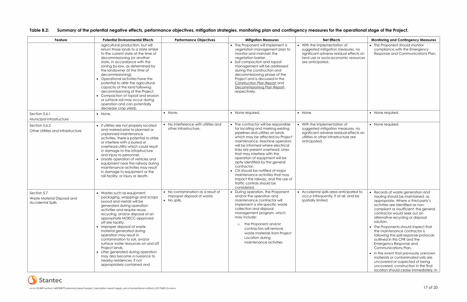
cn m:\01609\active\160950879\planning\report\project_description report\appb_sum-of-potential-env-effects_20170602_fin.docx 17 of 20
Table B.2: Summary of the potential negative effects, performance objectives, mitigation strategies, monitoring plan and contingency measures for the operational stage of the Project.
Feature Potential Environmental Effects Performance Objectives Mitigation Measures Net Effects Monitoring and Contingency Measures agricultural production, but will return those lands to a state similar to the current state at the time of decommissioning (or another state, in accordance with the zoning by-law, as determined by the landowner at the time of decommissioning).
• Operational activities have the potential to alter the agricultural capacity of the land following decommissioning of the Project.
• Compaction of topsoil and erosion or surface soil may occur during operation and can potentially decrease crop yields.
• The Proponent will implement a vegetation management plan to monitor and maintain the vegetation barrier.
• Soil compaction and topsoil management will be addressed during the construction and decommissioning phase of the Project and is discussed in the Construction Plan Report and Decommissioning Plan Report, respectively.
• With the implementation of suggested mitigation measures, no significant adverse residual effects on land use or socio-economic resources are anticipated.
• The Proponent should monitor compliance with the Emergency Response and Communications Plan.
Section 5.6.1 Municipal Infrastructure
• None. • None. • None required. • None. • None required.
Section 5.6.2 Other Utilities and Infrastructure
• If utilities are not properly located and marked prior to planned or unplanned maintenance activities, there is potential to strike or interfere with a buried or overhead utility which could result in damage to the infrastructure and injury to personnel.
• Unsafe operation of vehicles and equipment near the railway during maintenance activities may result in damage to equipment or the rail facility, or injury or death.
• No interference with utilities and other infrastructure.
• The contractor will be responsible for locating and marking existing pipelines and utilities on lands which may be affected by Project maintenance. Machine operators will be informed where electrical lines are present overhead. Lines that may interfere with the operation of equipment will be aptly identified by the general contractor.
• CN should be notified of major maintenance activities that may impact the railway, and the use of traffic controls should be considered.
• With the implementation of suggested mitigation measures, no significant adverse residual effects on utilities or other infrastructure are anticipated.
• None required.
Section 5.7 Waste Material Disposal and Accidental Spills
• Wastes such as equipment packaging, wrappings and scraps (wood and metal) will be generated during operation activities and require reuse, recycling, and/or disposal at an appropriate MOECC-approved off-site facility.
• Improper disposal of waste material generated during operation may result in contamination to soil, and/or surface water resources on and off Project lands.
• Litter generated during operation may also become a nuisance to nearby residences, if not appropriately contained and
• No contamination as a result of improper disposal of waste.
• No spills.
• During operation, the Proponent and/or the operation and maintenance contractor will implement a site-specific waste collection and disposal management program, which may include:
o the Proponent and/or contractors will remove waste materials from Project Location during maintenance activities
• Accidental spills area anticipated to occur infrequently, if at all, and be spatially limited.
• Records of waste generation and hauling should be maintained, as appropriate. Where a third party’s activities are identified as non-compliant or insufficient, the general contractor would seek out an alternative recycling or disposal solution.
• The Proponents should inspect that the maintenance contractor is following the spill response protocols outlined in this CPR and the Emergency Response and Communications Plan.
• In the event that previously unknown materials or contaminated soils are uncovered or suspected of being uncovered, construction in the find location should cease immediately. In

cn m:\01609\active\160950879\planning\report\project_description report\appb_sum-of-potential-env-effects_20170602_fin.docx 18 of 20
Table B.2: Summary of the potential negative effects, performance objectives, mitigation strategies, monitoring plan and contingency measures for the operational stage of the Project.
Feature Potential Environmental Effects Performance Objectives Mitigation Measures Net Effects Monitoring and Contingency Measures allowed to blow off the construction site.
o labelling and proper storage of liquid wastes (e.g. used oil and solvents) in a secure area that would contain materials in the event of a spill
o as appropriate, spill kits (e.g. containing absorbent cloths and disposal containers) will be provided on-site during maintenance activities and at the control building
o dumping or burying wastes within the Project sites would be prohibited
o non-hazardous waste will be disposed at a registered waste disposal site(s)
o if waste is generated that is not solid non-hazardous waste, a Generator Registration Number is required from the MOECC and the generator would have obligations regarding manifesting of waste. Compliance with Schedule 4 of O. Reg. 347 is mandatory when determining waste category
o implementation of an on-going waste management program consisting of reduction, reuse, and recycling of materials.
• Equipment maintenance and refueling, and other potentially contaminating activities, will occur in designated areas. Large quantities of fuel, lubricating oils, and other fluids associated with maintenance activities will not be stored at the site. The storage of minor quantities of fuels and lubricants on-site do not represent a significant potential adverse effect on the groundwater in the event of accidental spills.
such an instance, the Proponent should retain expert advice on assessing and developing a plan for soil sampling, handling, disposal and remediation.

cn m:\01609\active\160950879\planning\report\project_description report\appb_sum-of-potential-env-effects_20170602_fin.docx 19 of 20
Table B.2: Summary of the potential negative effects, performance objectives, mitigation strategies, monitoring plan and contingency measures for the operational stage of the Project.
Feature Potential Environmental Effects Performance Objectives Mitigation Measures Net Effects Monitoring and Contingency Measures Standard containment facilities and emergency response materials would be maintained on-site as required.
• In the unlikely event of an accidental spill, the response procedures noted in Section 3.7 of the Construction Plan Report will be implemented. Follow-up monitoring /inspections would be implemented in the event of an accidental spill/leak, as appropriate. Remedial actions may be required in the event that follow-up monitoring indicates adverse effects to natural features.
Section 5.8 Public Health and Safety
• Potential risk of fire associated with an accident or malfunction.
• Possible failure of overhead line poles.
• Zero project related injuries. • The primary method of minimizing potential public health and safety risks will be by installing perimeter fencing to restrict site access and prevent trespassing and vandalism (see Section 3.3.2).
• The Proponent will reduce accidents and malfunctions by providing proper training and education of staff operating the control system and maintaining the panels.
• Solar panels and associated electrical equipment will be installed and maintained in accordance with applicable safety standards.
• The primary preventative measure taken to avoid pole failure during operation is at the design stage. Overhead lines will be designed and constructed in accordance with applicable regulatory guidelines.
• Should maintenance activities be required within a municipal road allowance, access to residential properties should be maintained.
• Safety fences should be installed at the edge of the maintenance areas where public safety considerations are required. Traffic controllers and appropriate signage should be utilized as necessary.
• The Proponent will maintain communication with the municipality and provide them
• None. • The Proponent should review Project complaints on a regular basis and respond accordingly in a timely manner, in accordance with the Complaint Response Protocol.

cn m:\01609\active\160950879\planning\report\project_description report\appb_sum-of-potential-env-effects_20170602_fin.docx 20 of 20
Table B.2: Summary of the potential negative effects, performance objectives, mitigation strategies, monitoring plan and contingency measures for the operational stage of the Project.
Feature Potential Environmental Effects Performance Objectives Mitigation Measures Net Effects Monitoring and Contingency Measures with an emergency response plan for the Project.
• Specialized equipment beyond what is typically required to respond to electrical fires is not required for fires involving solar panels. The Emergency Response and Communications Plan is provided in Section 7.0.