Embed Size (px)
Citation preview

CENGRS GEOTECHNICA PVT. LTD. C I V I L & G E O T E C H N I C A L E N G I N E E R S
CORPORATE OFFICE: A-100, SECTOR-63, NOIDA (U.P.)- 201309, INDIA Tel: +91(120) 420 6771, Fax : +91(120)420 6775, E-mail: [email protected]
REGD. OFFICE: B-3/87 SAFDARJUNG ENCLAVE, NEW DELHI- 110029, INDIA
Visit us at : www.cengrs.com
FINAL REPORT ON:
GEOTECHNICAL INVESTIGATION FOR ENVIRONMENTAL REGULATORY TRAINING
INSTITUTE AT NIMLI VILLAGE, TIJARA ALWAR, RAJASTHAN
Submitted to:
M/s. Nilayam Housing Pvt. Ltd. 4, Windmill Place Aya Nagar Village New Delhi-110047

212073-B i
CENGRS GEOTECHNICA PVT. LTD. Job No. Sheet No.
FINAL REPORT ON:
GEOTECHNICAL INVESTIGATION FOR ENVIRONMENTAL REGULATORY TRAINING
INSTITUTE AT NIMLI VILLAGE, TIJARA ALWAR, RAJASTHAN
Submitted to:
M/s. Nilayam Housing Pvt. Ltd. 4, Windmill Place Aya Nagar Village New Delhi-110047

212073-B ii
CENGRS GEOTECHNICA PVT. LTD. Job No. Sheet No.
TABLE OF CONTENTS
Sheet No.
1.0 INTRODUCTION.......................................................................................... 1 1.1 Project Description ............................................................................ 1 1.2 Purposes of Study............................................................................. 1 1.3 Details of Test Locations................................................................... 1
2.0 FIELD INVESTIGATIONS ........................................................................... 2 2.1 Soil Borings........................................................................................ 2 2.2 Groundwater ...................................................................................... 3
3.0 LABORATORY TESTS............................................................................... 3 4.0 GENERAL SITE CONDITIONS .................................................................. 4
4.1 Site Details......................................................................................... 4 4.2 Site Stratigraphy................................................................................ 5 4.3 Groundwater ...................................................................................... 7
5.0 FOUNDATION ANALYSIS AND RECOMMENDATIONS ........................ 7 5.1 General .............................................................................................. 7 5.2 Liquefaction Potential........................................................................ 7 5.3 Foundation Type and Depth ............................................................. 8 5.4 Open Foundations............................................................................. 9 5.5 Definition of Gross and Net Bearing Pressure ............................... 12 5.6 Basement Design ............................................................................ 13
6.0 FOUNDATION CONSTRUCTION CONSIDERATIONS.......................... 13 6.1 Excavations ..................................................................................... 13 6.2 Fill Placement and Compaction...................................................... 13 6.3 Foundation Level Preparation......................................................... 14 6.4 Chemical Attack............................................................................... 14 6.5 Variability in Subsurface Conditions............................................... 15
7.0 SUMMARY OF PRINCIPAL FINDINGS AND RECOMMENDATIONS.. 15 8.0 CLOSURE.................................................................................................. 16

212073-B iii
CENGRS GEOTECHNICA PVT. LTD. Job No. Sheet No.
TABLES Table No.
Soil Profiles 1 to 10 Chemical Test Results 11
Engineering Description of Soils 12 Uncertainty in Laboratory Measurements 13
ILLUSTRATIONS Fig. No.
Plan of Field Investigation 1 Summary of Borehole Profile 2a & 2b
Standard Penetration Test Results (Field & Corrected) 3a to 3d Grain Size Analysis 4 to 13 Shear Test Results 14 to 31
Typical Calculations: Sheet Nos. 1 to 12 --------------------------------------------------------

212073-A 1
CENGRS GEOTECHNICA PVT. LTD. Job No. Sheet No.
1.0 INTRODUCTION
1.1 Project Description
M/s. Centre for Science & Environment is planning to develop Environmental Regulatory Training Institute at Nimli, Alwar, Rajasthan spread over an area of 10.3 Acres. Some 3-4 storeyed buildings without basement alongwith Dining Block, Administrative Block and Teaching Block with one basement and other structures for various facilities shall be constructed on site.
A layout plan showing the locations of our field investigations is
presented on Fig. No.1
1.2 Purposes of Study
The overall purposes of this study are to investigate the stratigraphy at the site and to develop geotechnical recommendations for foundation design and construction. To accomplish these purposes, the study was conducted in the following phases: (a) drilling ten boreholes to 15.0 m depth or refusal, whichever is
earlier in order to determine site stratigraphy and to collect disturbed and undisturbed soil samples for laboratory testing;
(b) testing selected soil samples in the laboratory to determine
pertinent index and engineering properties of the soils; and 1.3 Details of Test Locations
The details of borehole numbers and locations, ground elevations, co ordinates and borehole termination depths are presented below:
Borehole Termination Borehole No./ Locations
Ground Elevation,
RL, m
Coordi-nates, m Depth, m RL, m
BH-1 (Near nallah and Workers
village) 289.5 3880711.0 N
690018.5 E 15.45 274.1
BH-2 (Support Staff Residences) 289.1 3880733.0
N690078.0 E 15.45 273.7

212073-A 2
CENGRS GEOTECHNICA PVT. LTD. Job No. Sheet No.
Borehole Termination Borehole No./ Locations
Ground Elevation,
RL, m
Coordi-nates, m Depth, m RL, m
BH-3
(Hostel Block) 291.8 3880744.5N
690043.5 E 15.45 276.3
BH-4
(Kitchen and Dining Hall) 301.3 3880739.0 N
690043.5 E 3.10 298.2
BH 5 (Administrative Block) 301.4 3880717.0 N
690241.5 E 15.45 285.9
BH 6 (Teaching Block) 302.5 3880677.0 N 690245.5 E 15.45 287.0
BH 7 (Staff Residence) 302.5 3880651.0 N 690187.0 E 15.45 287.0
BH-8
(Directors Residence) 296.2 3880632.5 N
690119.0 E 15.45. 280.7
BH-9
(Open Area) 295.9 3880632.5 N
690018.5 E 15.45. 280.4
BH-10 (Open Area) 294.3 3880688.5 N 690130.5 E 15.45. 278.8
* Levels read off from contour drawing given to us
2.0 FIELD INVESTIGATIONS 2.1 Soil Borings The borings were progressed using a shell and auger to the specified depth or refusal, whichever is encountered earlier. The diameter of the borehole was 150 mm. Where caving of the borehole occurred, casing was used to keep the borehole stable. The work was in general accordance with IS:1892-1979.
Standard Penetration Tests (SPT) were conducted in the
boreholes at 1.5 m intervals by connecting a split spoon sampler to ‘A’ rods and driving it by 45 cm using a 63.5 kg hammer falling freely from a height of 75 cm. The tests were conducted in accordance with IS:2131-1981.

212073-A 3
CENGRS GEOTECHNICA PVT. LTD. Job No. Sheet No.
The number of blows for each 15 cm of penetration of the split
spoon sampler was recorded. The blows required to penetrate the initial 15 cm of the split spoon for seating the sampler is ignored due to the possible presence of loose materials or cuttings from the drilling operation. The cumulative number of blows required to penetrate the balance 30 cm of the 45 cm sampling interval is termed the SPT value or the ‘N’ value.
The ‘N’ values are presented on the soil profile for each borehole. Refusal to further boring penetration was considered when the ‘N’ values exceed 100 or when practical refusal to further penetration by shell and auger was encountered.
Disturbed samples were collected from the split spoon after conducting SPT. The samples were preserved in transparent polythene bags. Undisturbed samples were collected at 3.0 m interval by attaching 100 mm diameter thin walled ‘Shelby’ tubes and driving the sampler using a 63.5 kg hammer in accordance with IS:2132-1986. The tubes were sealed with wax at both ends. All samples were transported to our NABL accredited laboratory at Delhi for further examination and testing. 2.2 Groundwater Groundwater level was measured in the boreholes 24 hours after drilling and sampling was completed. The measured water levels are recorded on the individual soil profiles.
3.0 LABORATORY TESTS
The laboratory testing has been carried out in our NABL accredited laboratory. The quality procedures in our laboratory conform to ISO/IEC-17025-2005. The laboratory testing programme was aimed to verify the field classifications and developing parameters for engineering analysis. All testing was performed in accordance with the current applicable IS specifications. The following tests were conducted on selected soil samples recovered from the boreholes:
212073-A 4
CENGRS GEOTECHNICA PVT. LTD. Job No. Sheet No.
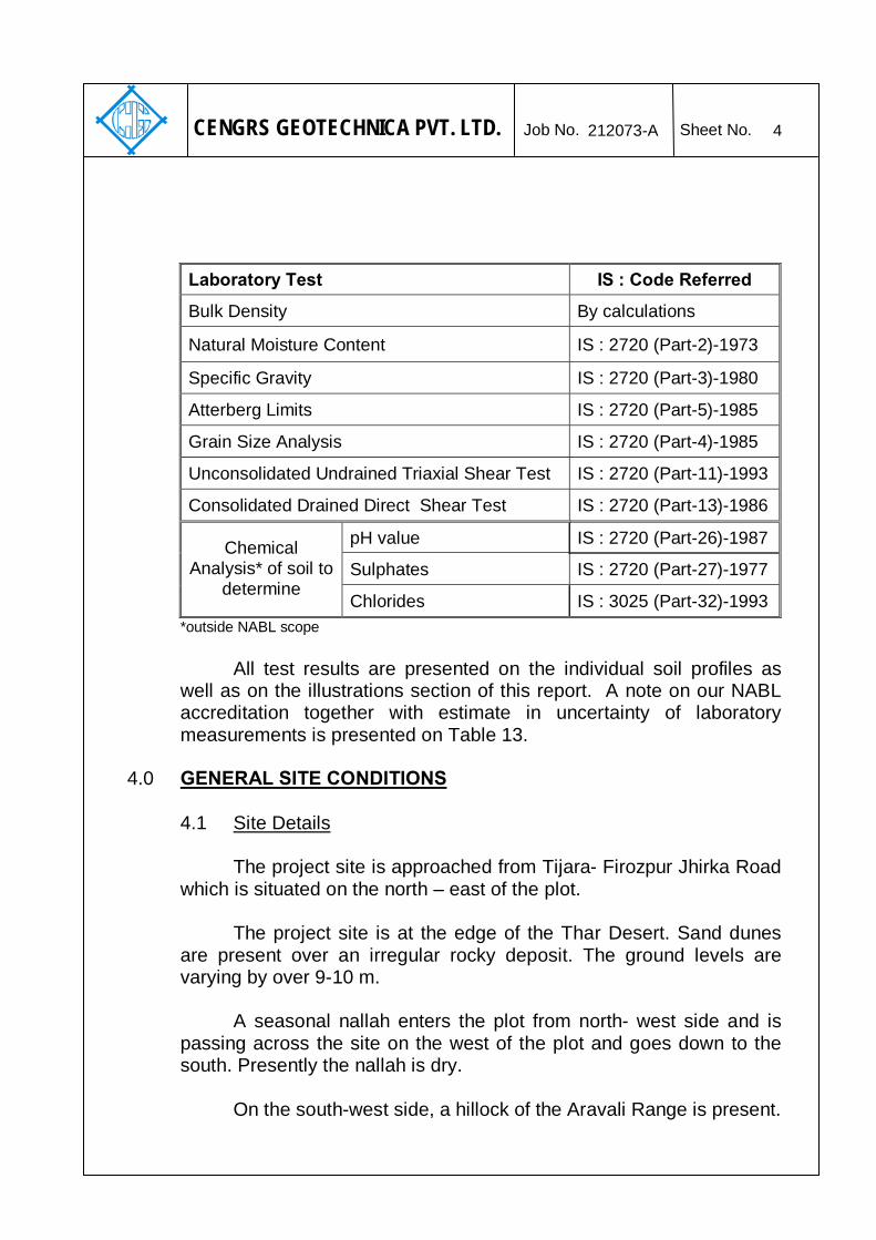
Laboratory Test IS : Code Referred
Bulk Density By calculations
Natural Moisture Content IS : 2720 (Part-2)-1973
Specific Gravity IS : 2720 (Part-3)-1980
Atterberg Limits IS : 2720 (Part-5)-1985
Grain Size Analysis IS : 2720 (Part-4)-1985
Unconsolidated Undrained Triaxial Shear Test IS : 2720 (Part-11)-1993
Consolidated Drained Direct Shear Test IS : 2720 (Part-13)-1986
pH value IS : 2720 (Part-26)-1987
Sulphates IS : 2720 (Part-27)-1977 Chemical
Analysis* of soil to determine
Chlorides IS : 3025 (Part-32)-1993 *outside NABL scope All test results are presented on the individual soil profiles as well as on the illustrations section of this report. A note on our NABL accreditation together with estimate in uncertainty of laboratory measurements is presented on Table 13.
4.0 GENERAL SITE CONDITIONS
4.1 Site Details
The project site is approached from Tijara- Firozpur Jhirka Road which is situated on the north – east of the plot.
The project site is at the edge of the Thar Desert. Sand dunes
are present over an irregular rocky deposit. The ground levels are varying by over 9-10 m.
A seasonal nallah enters the plot from north- west side and is
passing across the site on the west of the plot and goes down to the south. Presently the nallah is dry.
On the south-west side, a hillock of the Aravali Range is present.

212073-A 5
CENGRS GEOTECHNICA PVT. LTD. Job No. Sheet No.
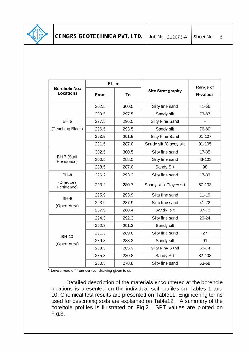
4.2 Site Stratigraphy
The soils at the site are aeolean in nature and consist of silty fine sand from ground surface to about 9-14.0 m depth underlain by sandy silt / clayey silt to the final explored depth of 15.45 m At BH 4 silty fine sand is met underlain by rock.
The site stratigraphy encountered at each borehole location is
summarized below with borehole Nos., locations, surface elevations, range of SPT ‘N’-values and co-ordinates.
RL, m
Borehole No./ Locations From To
Site Stratigraphy Range of
N-values
289.5 284.5 Silty fine sand 28-78
284.5 283.5 Sandy Silt -
283.5 278.5 Silty fine sand 42-65
BH-1
(Near nallah and Workers village)
278.5 274.1 Sandy silt 43-61
289.1 284.1 Silty fine sand 15-26
284.1 278.1 Silty fine sand 33-51 BH-2
(Support Staff Residences) 278.1 273.7 Sandy silt 36-56
291.8 286.8 Silty fine sand 11-18
286.8 285.8 Sandy Silt -
285.8 282.8 Silty fine sand 9-17
BH-3
(Hostel Block)
282.8 276.3 Sandy Silt/Clayey Silt 54-79
301.3 299.3 Silty fine sand 12-24
299.3 298.3 Gravel mixed with sand -
BH-4
(Kitchen and Dining Hall)
298.3 298.2 Rock (Quartzite) Ref/10 cm
301.4 299.4 Silty fine sand 13-29
299.4 298.4 Sandy silt -
298.4 296.9 Silty fine sand 63
BH 5 (Administrative
Block)
296.9 285.9 Sandy silt /Clayey silt 72-96
* Levels read off from contour drawing given to us
212073-A 6
CENGRS GEOTECHNICA PVT. LTD. Job No. Sheet No.
RL, m Borehole No./
Locations From To Site Stratigraphy
Range of
N-values
302.5 300.5 Silty fine sand 41-56
300.5 297.5 Sandy silt 73-87
297.5 296.5 Silty Fine Sand -
296.5 293.5 Sandy silt 76-80
293.5 291.5 Silty Fine Sand 91-107
BH 6
(Teaching Block)
291.5 287.0 Sandy silt /Clayey silt 91-105
302.5 300.5 Silty fine sand 17-35
300.5 288.5 Silty fine sand 43-103 BH 7 (Staff Residence)
288.5 287.0 Sandy Silt 98
296.2 293.2 Silty fine sand 17-33 BH-8
(Directors Residence) 293.2 280.7 Sandy silt / Clayey silt 57-103
295.9 293.9 Siltu fine sand 11-19
293.9 287.9 Siltu fine sand 41-72 BH-9
(Open Area) 287.9 280.4 Sandy silt 37-73
294.3 292.3 Silty fine sand 20-24
292.3 291.3 Sandy silt -
291.3 289.8 Silty fine sand 27
289.8 288.3 Sandy silt 91
288.3 285.3 Silty Fine Sand 60-74
285.3 280.8 Sandy Silt 82-108
BH-10
(Open Area)
280.3 278.8 Silty fine sand 53-68
* Levels read off from contour drawing given to us Detailed description of the materials encountered at the borehole
locations is presented on the individual soil profiles on Tables 1 and 10. Chemical test results are presented on Table11. Engineering terms used for describing soils are explained on Table12. A summary of the borehole profiles is illustrated on Fig.2. SPT values are plotted on Fig.3.

212073-A 7
CENGRS GEOTECHNICA PVT. LTD. Job No. Sheet No.
4.3 Groundwater
Based on our measurements in the completed boreholes,
groundwater was not met to the final explored depth of 15.0 m during the period of our field investigation (May-June, 2012). The HFL of the Nallah should be ascertained to the highest water level for design.
5.0 FOUNDATION ANALYSIS AND RECOMMENDATIONS
5.1 General A suitable foundation for any structure should have an adequate factor of safety against exceeding the bearing capacity of the supporting soils. Also the vertical movements due to compression of the soils should be within tolerable limits for the structure. We consider that foundation designed in accordance with the recommendations given herein will satisfy these criteria.
5.2 Liquefaction Potential
As per IS:1893-2002, liquefaction during earthquakes is likely in
fine sand (SP) below water table for SPT values less than 15 to 5 m depth and less than 25 below 10 m depth
. Dune sand is encountered all over the project site. The soils at
the site consist of silty fine sand from ground surface to the final explored depth of 12.45 m. Groundwater was not met to the final explored depth of 12.0 m during our field investigation (May-June, 2012)
On review of all the soil parameters like in-situ density, dry
density, SPT values, soil gradations, groundwater conditions etc., we are of the opinion that liquefaction is not likely to occur at this site during earthquakes.
According to Fig.1 of IS: 1893 (Part-1)-2002 showing seismic
zones, the site falls under Zone-IV. The design for seismic forces should be done considering the design parameters for Zone-IV.

212073-A 8
CENGRS GEOTECHNICA PVT. LTD. Job No. Sheet No.
5.3 Foundation Type and Depth
We recommend that open foundations may be used to support the structural loads of the buildings bearing at 1.0-4.0 m depth below the final finished level surrounding the respective building. These are tabulated as under:
Borehole No and Location
Range of Existing Ground Level within the Building
Line, RL, m** Final Finished Level, RL, m
BH1(Near Nallah and Workers Village) 288.6-290.4 289.5*
BH 2 (Support Staff Residence) 288.5-293.4 289.5
BH 3 (Hostel Block) 288.5-293.4 291.5
BH 4 (Kitchen and Dining Hall) 299.0-301.7 302.5
BH 5 (Administrative Block) 300.7-302.5 303.4
BH 6 (Teaching Block) 300.9-303.8 304.0
BH 7 (Staff Residences) 300.4-303.2 302.5
BH 8 (Director General’s Residence) 294.2-298.1 297.7
BH 9 (Open Area) 289.0-296.6 295.9*
BH 10 (Open Area) 292.5-296.6 294.3* * Existing Ground Level at the Borehole Location. ** As read off from Contour Map
An interconnecting plinth beam should be provided to restrict
differential settlement and to give rigidity to the structure.
212073-A 9
CENGRS GEOTECHNICA PVT. LTD. Job No. Sheet No.
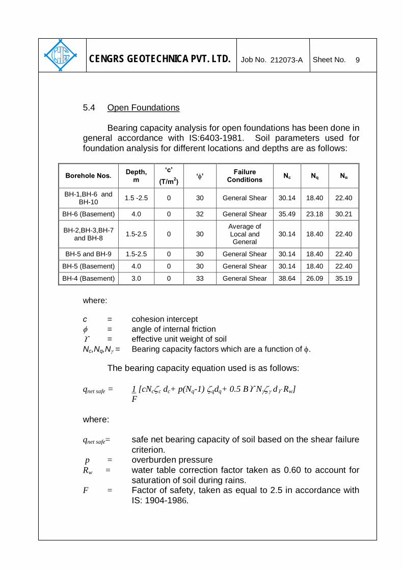
5.4 Open Foundations
Bearing capacity analysis for open foundations has been done in
general accordance with IS:6403-1981. Soil parameters used for foundation analysis for different locations and depths are as follows:
Borehole Nos. Depth, m
‘c’
(T/m2) ‘φ’ Failure Conditions Nc Nq Nα
BH-1,BH-6 and BH-10 1.5 -2.5 0 30 General Shear 30.14 18.40 22.40
BH-6 (Basement) 4.0 0 32 General Shear 35.49 23.18 30.21
BH-2,BH-3,BH-7 and BH-8 1.5-2.5 0 30
Average of Local and General
30.14 18.40 22.40
BH-5 and BH-9 1.5-2.5 0 30 General Shear 30.14 18.40 22.40
BH-5 (Basement) 4.0 0 30 General Shear 30.14 18.40 22.40
BH-4 (Basement) 3.0 0 33 General Shear 38.64 26.09 35.19
where: c = cohesion intercept φ = angle of internal friction ϒ = effective unit weight of soil
Nc,Nq,Nγ = Bearing capacity factors which are a function of φ. The bearing capacity equation used is as follows:
qnet safe = 1 [cNcζc dc+ p(Nq-1) ζqdq+ 0.5 Bϒ Nγζγ dϒ Rw]
F where:
qnet safe= safe net bearing capacity of soil based on the shear failure
criterion. p = overburden pressure Rw = water table correction factor taken as 0.60 to account for
saturation of soil during rains. F = Factor of safety, taken as equal to 2.5 in accordance with IS: 1904-1986.

212073-A 10
CENGRS GEOTECHNICA PVT. LTD. Job No. Sheet No.
ζc,ζq,ζγ= Shape factors. For Strip footings, ζc = ζq = ζγ = 1 For Square footing, ζc = 1.3, ζq = 1.2, ζγ = 0.6 dc ,dq, dγ = Depth factors
For φ ≤ 10, dc = 1 + 0.2 tan (45 + φ / 2) D / B, dq = dγ = 1 For φ > 10, dq = dγ = 1 + 0.1 tan (45 + φ / 2) D / B
For the soil conditions encountered at this site, an average of local and general shear failure conditions has been used for analysis for BH-2, BH-3, BH-7 and BH-8 locations. For other locations general shear condition has been used.
Appropriate values have been substituted into the bearing capacity equation given above to compute the safe net bearing capacity. The values have been checked to determine the settlement of the foundation under the safe bearing pressure. The allowable bearing pressure has been taken as the lower of the two values computed from the bearing capacity shear failure criterion as well as that computed from the tolerable settlement criterion.
Settlement analysis has been performed based on the SPT
values in accordance with Clause 9.1.4 of IS 8009 (Part 1) - 1976 Fig.9. As per IS 1904-1986, the tolerable total settlement is taken as 50 mm.
We recommend the following value of net allowable bearing
pressure for open foundations at 1.5-4.0 m depths below the final finished level of the respective building.
Recommended Net Allowable Bearing,
Pressure, T/m2
Corresponding Allowable Gross
Bearing Pressure, T/m2
Locations
Foundation Embedment Depth below
final finished
level, RL, m
40 m
m
Settl
emen
t
50 m
m
Settl
emen
t
40 m
m
Settl
emen
t
50 m
m
Settl
emen
t
Proposed Modulus
of Subgrade Reaction,
kg/cm3
1.5(288.0) 16.8 21.0 19.3 23.5 2.0 BH1(Near Nallah and Workers
Village) 2.5(287.0) 19.2 24.0 23.5 28.3 2.5

212073-A 11
CENGRS GEOTECHNICA PVT. LTD. Job No. Sheet No.
Recommended Net Allowable Bearing,
Pressure, T/m2
Corresponding Allowable Gross
Bearing Pressure, T/m2
Locations
Foundation Embedment Depth below
final finished
level, RL, m
40 m
m
Settl
emen
t
50 m
m
Settl
emen
t
40 m
m
Settl
emen
t
50 m
m
Settl
emen
t
Proposed Modulus
of Subgrade Reaction,
kg/cm3
1.5(288.0) 10.8 13.5 13.3 16.0 1.4 BH 2 (Support Staff Residence) 2.5(287.0) 13.2 16.5 17.5 20.8 1.7
1.5(290.0) 10.8 13.5 13.3 16.0 1.4 BH 3 (Hostel Block) 2.5(289.0) 13.2 16.5 17.5 20.8 1.7
BH 4 (Kitchen and Dining Hall)
3.0(299.5) and below 24.0 30.0 29.1 35.1 5.0
1.5(301.9) 16.8 21.0 19.3 23.5 2.0
2.5(300.9) 20.8 26.0 25.1 30.3 2.8 BH 5
(Administrative Block) 4.0(299.4) 24.0 30.0 30.9 36.9 3.5
1.5(302.5) 16.8 21.0 19.3 23.5 2.0
2.5(301.5) 19.2 24.0 23.5 28.3 2.5 BH 6 (Teaching Block)
4.0(300.0) 24.0 30.0 30.9 36.9 3.5
1.5(301.0) 10.8 13.5 13.3 16.0 1.4 BH 7 (Staff Residences) 2.5(300.0) 13.2 16.5 17.5 20.8 1.7
1.5(296.2) 10.8 13.5 13.3 16.0 1.4 BH 8 (Director General’s
Residence) 2.5(295.2) 13.2 16.5 17.5 20.8 1.7
1.5(294.4) 16.8 21.0 19.3 23.5 2.0 BH 9 (Open Area)
2.5(293.4) 20.8 26.0 25.1 30.3 2.8
1.5(292.8) 16.8 21.0 19.3 23.5 2.0 BH 10 (Open Area) 2.5(291.8) 19.2 24.0 23.5 28.3 2.5
The above recommended values include a bearing capacity
safety factor of 2.5. The appropriate value of net bearing pressure may be selected based on permissible settlement criterion. Net bearing pressures for foundations at intermediate depths may be interpolated linearly between the values given above.

212073-A 12
CENGRS GEOTECHNICA PVT. LTD. Job No. Sheet No.
In order to restrict the influence of adjacent footings on each
other (for isolated footing), the lateral edge-to-edge spacing between the foundations should at least be equal to “0.8B” where ”B” is the width of the larger footing. In case this criterion cannot be satisfied, combined footings or raft foundations may be provided.
5.5 Definition of Gross and Net Bearing Pressure
By definition, the net allowable bearing pressure is the intensity
of loading which gives the safety against both the shear failure criteria as well as settlement criteria.
For the purposes of this report, the net allowable bearing
pressure should be calculated as the difference between total load on the foundation and the weight of the soil overlying the foundation divided by the effective area of the foundation. The gross bearing pressure is the total pressure at the foundation level including overburden pressure and surcharge load. The following equations may be used - qnet = [(Ps + Wf +Ws) / Af] - Sv qgross = qnet + Sv = (Ps + Wf + Ws) / Af where: qnet = net allowable bearing pressure qgross = gross bearing pressure Ps = superimposed static load on foundation Wf = weight of foundation Ws = weight of soil overlying foundation Af = effective area of foundation Sv = overburden pressure at foundation level prior to excavation for foundation.
It may please be noted that safe bearing pressures
recommended in this report refer to “net values”. The gross bearing may be computed by adding the overburden pressure to the net bearing pressure. Advantage of gross bearing pressure may be taken while designing the basements. Fill placed above EGL should be treated as a surcharge load.
212073-A 13
CENGRS GEOTECHNICA PVT. LTD. Job No. Sheet No.
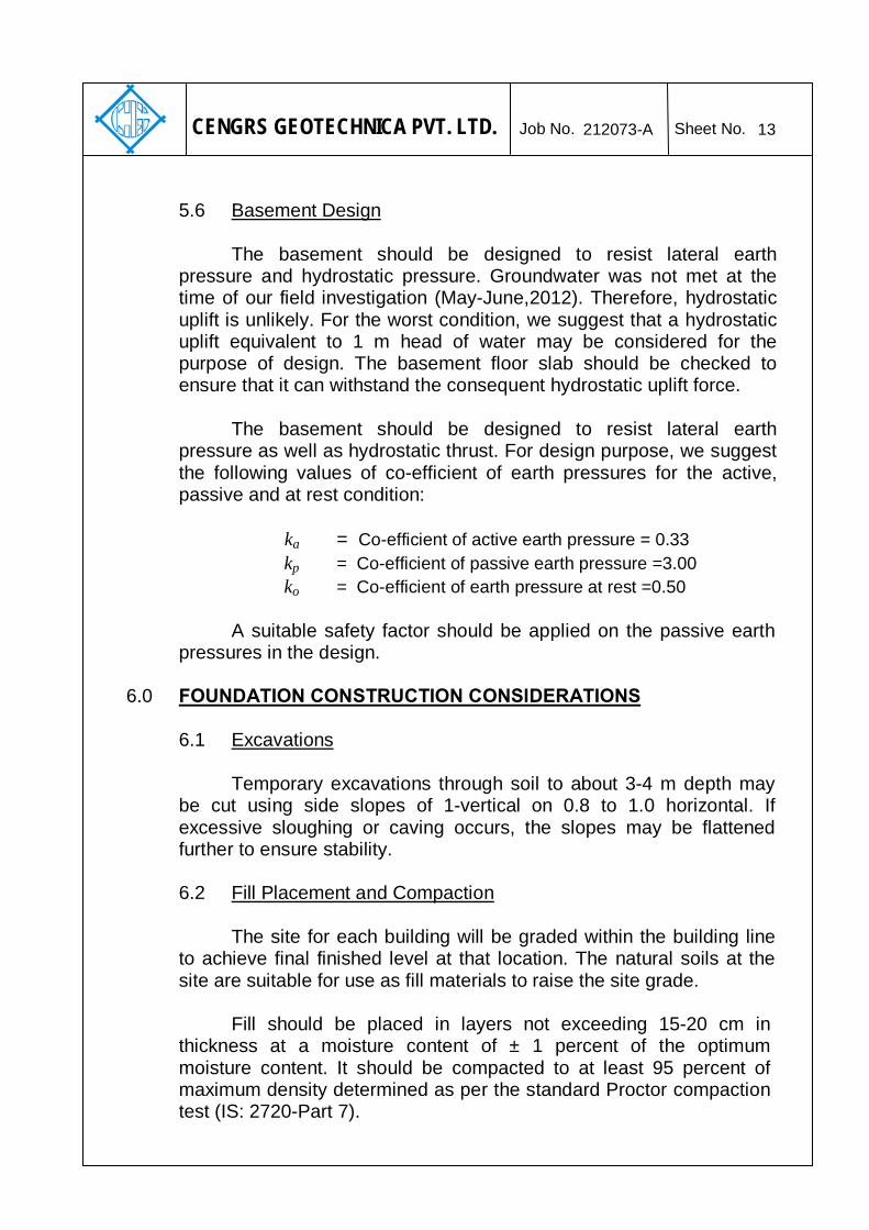
5.6 Basement Design
The basement should be designed to resist lateral earth pressure and hydrostatic pressure. Groundwater was not met at the time of our field investigation (May-June,2012). Therefore, hydrostatic uplift is unlikely. For the worst condition, we suggest that a hydrostatic uplift equivalent to 1 m head of water may be considered for the purpose of design. The basement floor slab should be checked to ensure that it can withstand the consequent hydrostatic uplift force. The basement should be designed to resist lateral earth pressure as well as hydrostatic thrust. For design purpose, we suggest the following values of co-efficient of earth pressures for the active, passive and at rest condition:
ka = Co-efficient of active earth pressure = 0.33
kp = Co-efficient of passive earth pressure =3.00 ko = Co-efficient of earth pressure at rest =0.50
A suitable safety factor should be applied on the passive earth pressures in the design.
6.0 FOUNDATION CONSTRUCTION CONSIDERATIONS
6.1 Excavations
Temporary excavations through soil to about 3-4 m depth may
be cut using side slopes of 1-vertical on 0.8 to 1.0 horizontal. If excessive sloughing or caving occurs, the slopes may be flattened further to ensure stability. 6.2 Fill Placement and Compaction The site for each building will be graded within the building line to achieve final finished level at that location. The natural soils at the site are suitable for use as fill materials to raise the site grade.
Fill should be placed in layers not exceeding 15-20 cm in thickness at a moisture content of ± 1 percent of the optimum moisture content. It should be compacted to at least 95 percent of maximum density determined as per the standard Proctor compaction test (IS: 2720-Part 7).

212073-A 14
CENGRS GEOTECHNICA PVT. LTD. Job No. Sheet No.
6.3 Foundation Level Preparation
The area shall be excavated up to the foundation level. All loose
soils should be removed and the exposed foundation bearing surface should be watered and compacted properly using rammers / rollers. The surface should then be protected from disturbances due to construction activities so that the foundations may bear on the natural undisturbed ground. For open foundations, we recommend the placement of a 75 to 100 mm thick “blinding layer” of lean concrete to facilitate placement of reinforcing steel and to protect the soils from disturbance.
In case mechanical means like excavators are deployed for
excavations, the excavations should be carried out up to 0.5 m above the proposed level. The last 0.5 m depth of excavation should be carried out manually, so that the founding soils are not disturbed / loosened.
6.4 Chemical Attack
Chemical test results are presented on Table 11. The results indicate that the soil contains about 0.09~0.11 percent sulphates and 0.01~0.04 percent chlorides. The pH value of soil is about 8.2~8.5 indicating slightly alkaline condition.
IS: 456-2000 recommends that precautions should be taken
against chemical degradation of concrete if
the sulphates content of the soils exceeds 0.2 percent, or the groundwater contains more than 300mg per litre of sulphates
(SO3). Comparing the test results with these specified limits, the
sulphate content of the soils is less than the specified limit. Groundwater is too deep to be of concern. The soils at the site fall in Class I classification as described on IS 456-2000, which indicates a mild potential for corrosion.

212073-A 15
CENGRS GEOTECHNICA PVT. LTD. Job No. Sheet No.
In our opinion, the soils at site are not aggressive to concrete.
We recommend the following measures as a good practice to limit the potential for chemical attack: (1) For open foundations concrete should contain minimum cement
content of 280 kg/m3. Ordinary Portland cement or any other cement type may be used.
(2) Water cement ratio in foundation concrete should not exceed
0.55. (3) A clear concrete cover over the reinforcement steel of at least
40mm should be provided for open foundations. (4) Foundation concrete should be densified adequately using a
vibrator so as to form a dense impervious mass.
6.5 Variability in Subsurface Conditions Subsurface conditions encountered during construction may vary somewhat from the conditions encountered during the site investigation. In case significant variations are encountered during construction, we request to be notified so that our engineers may review the recommendations in this report in light of these variations.
7.0 SUMMARY OF PRINCIPAL FINDINGS AND RECOMMENDATIONS M/s. Cengrs Geotechnica Pvt. Ltd. conducted a geotechnical
investigation for the proposed Environmental Regulatory Training Institute at Nimli, Alwar, Rajasthan for M/s. Centre for Science & Environment. The Institute is spread over an area of 10.3 Acres. The scope of investigation includes ten boreholes to 15 m depth.
The surficial soils at the site are aeolean in nature and consist of
silty fine sand underlain by sandy silt / clayey silt. Rock (quartzite) was met at BH-4. Groundwater was not met to the maximum depth drilled during our field investigation (May-June, 2012).
We recommend that open foundations may be used to support
the structural loads of the buildings bearing at 1.0-4.0 m depth below

212073-A 16
CENGRS GEOTECHNICA PVT. LTD. Job No. Sheet No.
the final finished level surrounding the respective building. Our recommended net and gross bearing pressures for the various buildingss are presented in Section 5.4 of this report.
8.0 CLOSURE
We appreciate the opportunity to perform this investigation for you and have pleasure in submitting this report. Please contact us when we can be of further service to you.
for CENGRS GEOTECHNICA PRIVATE LIMITED
(RAVI SUNDARAM) (SANJAY GUPTA) DIRECTOR MANAGING DIRECTOR
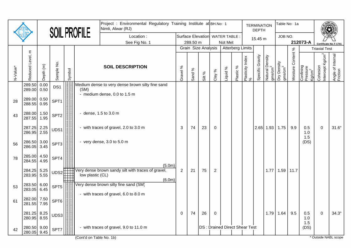
Table No: 1a
JOB NO.
Gra
vel %
San
d %
Silt
%
Cla
y %
Liqu
id %
Pla
stic
%
Pla
stic
ity In
dex
% Con
finin
g P
ress
ure
Kg/
cm2
Coh
esio
n In
terc
ept K
g/cm
2
Ang
le o
f Int
erna
l Fr
ictio
n
289.50 0.00289.00 0.50
289.00 0.50288.55 0.95
288.00 1.50287.55 1.95
287.25 2.25 3 74 23 0 2.65 1.93 1.75 9.9 0.5 0 31.6°286.95 2.55 1.0
1.5286.50 3.00 (DS)286.05 3.45
285.00 4.50284.55 4.95
284.25 5.25 2 21 75 2 1.77 1.59 11.7283.95 5.55
283.50 6.00283.05 6.45
282.00 7.50281.55 7.95
281.25 8.25 0 74 26 0 1.79 1.64 9.5 0.5 0 34.3°280.95 8.55 1.0
1.5280.50 9.00 DS : Drained Direct Shear Test (DS)280.05 9.45
(Cont'd on Table No. 1b)
Sym
bol
N-V
alue
*
Red
uced
Lev
el, m
Dep
th (m
)
Sam
ple
No.
Project : Environmental Regulatory Training Institute atNimli, Alwar (RJ)
- with traces of gravel, 6.0 to 8.0 m
* Outside NABL scope
42 SPT7
UDS3
SOIL DESCRIPTION
- with traces of gravel, 9.0 to 11.0 m
SPT4
Very dense brown silty fine sand (SM)
low plastic (CL)Very dense brown sandy silt with traces of gravel,
(5.0m)
UDS2
(6.0m)
- with traces of gravel, 2.0 to 3.0 m
SPT3
(SM) - medium dense, 0.0 to 1.5 m
- very dense, 3.0 to 5.0 m
- dense, 1.5 to 3.0 m
DS1
78
56
43 SPT2
28 SPT1
UDS1
53 SPT5
61 SPT6
212073-A
Medium dense to very dense brown silty fine sand
Moi
stur
e C
onte
nt % Triaxial Test
See Fig No. 115.45 m
Dry
Den
sity
gm
s/cm
3
Atterberg Limits
TERMINATION DEPTH
WATER TABLE :
Spe
cific
Gra
vity
Nat
ural
Den
sity
gm
s/cm
3
Grain Size Analysis
Surface Elevation289.50 m
BH.No: 1
Not MetLocation :
Certificate No.T-1741

Table No: 1b
JOB NO.
Gra
vel %
San
d %
Silt
%
Cla
y %
Liqu
id %
Pla
stic
%
Pla
stic
ity In
dex
% Con
finin
g P
ress
ure
Kg/
cm2
Coh
esio
n In
terc
ept K
g/cm
2
Ang
le o
f Int
erna
l Fr
ictio
n
279.00 10.50278.55 10.95
278.25 11.25 0 44 56 0 1.71 1.51 13.1277.95 11.55
277.50 12.00277.05 12.45
276.00 13.50275.55 13.95
275.25 14.25 34.4 17.4 17.0 1.97 1.72 14.2274.95 14.55
274.50 15.00274.05 15.45
N-V
alue
*
Red
uced
Lev
el, m
Dep
th (m
)
Sam
ple
No.
Sym
bol
Very dense brown silty fine sand (SM)
SOIL DESCRIPTION
Grain Size Analysis
Location :289.50 m
Very dense brown sandy silt, low plastic (CL)(11.0m)
See Fig No. 1
(15.45m)
WATER TABLE :
Project : Environmental Regulatory Training Institute atNimli, Alwar (RJ)
Surface Elevation
TERMINATION DEPTH
BH.No: 1
61 SPT9 - with traces of gravel, 12.0 to 15.45 m
UDS4
65 SPT8
43 SPT10
UDS5
52 SPT11
* Outside NABL scope
Moi
stur
e C
onte
nt %
Not Met 212073-A
Dry
Den
sity
gm
s/cm
3
Triaxial TestAtterberg Limits
Spe
cific
Gra
vity
15.45 m
Nat
ural
Den
sity
gm
s/cm
3
Certificate No.T-1741

Table No: 2a
JOB NO.
Gra
vel %
San
d %
Silt
%
Cla
y %
Liqu
id %
Pla
stic
%
Pla
stic
ity In
dex
% Con
finin
g P
ress
ure
Kg/
cm2
Coh
esio
n In
terc
ept K
g/cm
2
Ang
le o
f Int
erna
l Fr
ictio
n
289.11 0.00288.61 0.50
288.61 0.50288.16 0.95
287.61 1.50287.16 1.95
286.86 2.25 0 69 30 1 1.77 1.70 4.5286.56 2.55
286.11 3.00285.66 3.45
284.61 4.50284.16 4.95
283.86 5.25 0 80 20 0 2.65 1.82 1.60 13.7 0.5 0 32.5°283.56 5.55 1.0
1.5283.11 6.00 (DS)282.66 6.45
281.61 7.50281.16 7.95
280.86 8.25280.56 8.55
DS : Drained Direct Shear Test280.11 9.00279.66 9.45
(Cont'd on Table No. 2b)
Sym
bol
N-V
alue
*
Red
uced
Lev
el, m
Dep
th (m
)
Sam
ple
No.
Project : Environmental Regulatory Training Institute atNimli, Alwar (RJ)
* Outside NABL scope
49 SPT7
DS2
SOIL DESCRIPTION
- with pebbles and gravels (SM-GP), 8.0 to 9.0 m
SPT4
- dense, 6.0 to 11.0 m
UDS2
SPT3
- medium dense, 0.0 to 6.0 m
DS1
21
26
23 SPT2
15 SPT1
UDS1
33 SPT5
43 SPT6
212073-A
Medium dense to dense brown silty fine sand (SM)
Moi
stur
e C
onte
nt % Triaxial Test
See Fig No. 115.45 m
Dry
Den
sity
gm
s/cm
3
Atterberg Limits
TERMINATION DEPTH
WATER TABLE :
Spe
cific
Gra
vity
Nat
ural
Den
sity
gm
s/cm
3
Grain Size Analysis
Surface Elevation289.11 m
BH.No: 2
Not MetLocation :
Certificate No.T-1741

Table No: 2b
JOB NO.
Gra
vel %
San
d %
Silt
%
Cla
y %
Liqu
id %
Pla
stic
%
Pla
stic
ity In
dex
% Con
finin
g P
ress
ure
Kg/
cm2
Coh
esio
n In
terc
ept K
g/cm
2
Ang
le o
f Int
erna
l Fr
ictio
n
278.61 10.50278.16 10.95
277.86 11.25 2 21 75 2 1.85 1.52 21.6 0.5 0 31.7°277.56 11.55 1.0
1.5277.11 12.00 (DS)276.66 12.45
275.61 13.50275.16 13.95
274.86 14.25 34.9 15.6 19.3 1.88 1.66 13.3274.56 14.55
274.11 15.00273.66 15.45
DS : Drained Direct Shear Test
N-V
alue
*
Red
uced
Lev
el, m
Dep
th (m
)
Sam
ple
No.
Sym
bol
Very dense brown silty fine sand with traces of
SOIL DESCRIPTION
Grain Size Analysis
Location :289.11 m
Dense to very dense brown sandy silt with traces of gravel, low plastic (CL)
gravel (SM)(11.0m)
See Fig No. 1
- very dense, 15.0 to 15.45 m(15.45m)
- dense, 11.0 to 15.0 m
WATER TABLE :
Project : Environmental Regulatory Training Institute atNimli, Alwar (RJ)
Surface Elevation
TERMINATION DEPTH
BH.No: 2
36 SPT9
UDS3
51 SPT8
45 SPT10
UDS4
56 SPT11
* Outside NABL scope
Moi
stur
e C
onte
nt %
Not Met 212073-A
Dry
Den
sity
gm
s/cm
3
Triaxial TestAtterberg Limits
Spe
cific
Gra
vity
15.45 m
Nat
ural
Den
sity
gm
s/cm
3
Certificate No.T-1741

Table No: 3a
JOB NO.
Gra
vel %
San
d %
Silt
%
Cla
y %
Liqu
id %
Pla
stic
%
Pla
stic
ity In
dex
% Con
finin
g P
ress
ure
Kg/
cm2
Coh
esio
n In
terc
ept K
g/cm
2
Ang
le o
f Int
erna
l Fr
ictio
n
291.76 0.00291.26 0.50
291.26 0.50290.81 0.95
290.26 1.50289.81 1.95
289.51 2.25 10 77 13 0 1.78 1.67 6.4 0.5 0 34.5°289.21 2.55 1.0
1.5288.76 3.00 (DS)288.31 3.45
287.26 4.50286.81 4.95
286.51 5.25 2 12 81 5 1.83 1.59 15.0286.21 5.55
285.76 6.00285.31 6.45
284.26 7.50 DS : Drained Direct Shear Test283.81 7.95
283.51 8.25 0 74 26 0 2.65 1.83 1.67 9.5 0.5 0 33.5°283.21 8.55 1.0
1.5282.76 9.00 (DS)282.31 9.45
(Cont'd on Table No. 3b)
Sym
bol
N-V
alue
*
Red
uced
Lev
el, m
Dep
th (m
)
Sam
ple
No.
Project : Environmental Regulatory Training Institute atNimli, Alwar (RJ)
- loose, 6.0 to 7.5 m
* Outside NABL scope
71 SPT7
UDS3
low plastic (CL)
SOIL DESCRIPTION
(9.0m)Very dense brown sandy silt with traces of gravel,
SPT4
Loose to medium dense brown silty fine sand (SM)
low plastic (CL)Medium dense brown sandy silt with traces of gravel,
(5.0m)
UDS2
- medium dense, 7.5 to 9.0 m
(6.0m)
- with gravel, 2.0 to 3.0 m
SPT3
DS1
11
14
17 SPT2
18 SPT1
UDS1
9 SPT5
17 SPT6
212073-A
Medium dense brown silty fine sand (SM)
Moi
stur
e C
onte
nt % Triaxial Test
See Fig No. 115.45 m
Dry
Den
sity
gm
s/cm
3
Atterberg Limits
TERMINATION DEPTH
WATER TABLE :
Spe
cific
Gra
vity
Nat
ural
Den
sity
gm
s/cm
3
Grain Size Analysis
Surface Elevation291.76 m
BH.No: 3
Not MetLocation :
Certificate No.T-1741
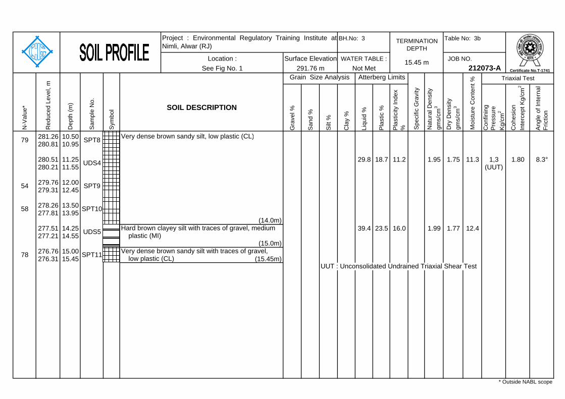
Table No: 3b
JOB NO.
Gra
vel %
San
d %
Silt
%
Cla
y %
Liqu
id %
Pla
stic
%
Pla
stic
ity In
dex
% Con
finin
g P
ress
ure
Kg/
cm2
Coh
esio
n In
terc
ept K
g/cm
2
Ang
le o
f Int
erna
l Fr
ictio
n
281.26 10.50280.81 10.95
280.51 11.25 29.8 18.7 11.2 1.95 1.75 11.3 1,3 1.80 8.3°280.21 11.55 (UUT)
279.76 12.00279.31 12.45
278.26 13.50277.81 13.95
277.51 14.25 39.4 23.5 16.0 1.99 1.77 12.4277.21 14.55
276.76 15.00276.31 15.45 (15.45m)
UUT : Unconsolidated Undrained Triaxial Shear Test
N-V
alue
*
Red
uced
Lev
el, m
Dep
th (m
)
Sam
ple
No.
Sym
bol
Very dense brown sandy silt, low plastic (CL)
SOIL DESCRIPTION
Grain Size Analysis
Location :291.76 m
plastic (MI)(15.0m)
See Fig No. 1
Very dense brown sandy silt with traces of gravel,
(14.0m)
WATER TABLE :
Project : Environmental Regulatory Training Institute atNimli, Alwar (RJ)
Surface Elevation
TERMINATION DEPTH
BH.No: 3
54 SPT9
UDS4
79 SPT8
58 SPT10
Nat
ural
Den
sity
gm
s/cm
3
UDS5 Hard brown clayey silt with traces of gravel, medium
78 SPT11
* Outside NABL scope
Moi
stur
e C
onte
nt %
Not Met 212073-A
Dry
Den
sity
gm
s/cm
3
Triaxial TestAtterberg Limits
Spe
cific
Gra
vity
15.45 m
low plastic (CL)
Certificate No.T-1741

Table No: 4
JOB NO.
Gra
vel %
San
d %
Silt
%
Cla
y %
Liqu
id %
Pla
stic
%
Pla
stic
ity In
dex
% Con
finin
g P
ress
ure
Kg/
cm2
Coh
esio
n In
terc
ept K
g/cm
2
Ang
le o
f Int
erna
l Fr
ictio
n
301.28 0.00300.78 0.50
300.78 0.50300.33 0.95
299.78 1.50299.33 1.95
299.03 2.25 86 10 5 0298.73 2.55
298.28 3.00298.18 3.10 (3.10m)
** 'Ref' refers to refusal (N>100) within the first 15 cm of seating penetration.
Sym
bol SOIL DESCRIPTION
N-V
alue
*
Red
uced
Lev
el, m
Dep
th (m
)
Sam
ple
No.
* Outside NABL scope
(3.0m)
SPT3 Rock formation
Dense gravel mixed with sand (GP-SP-SM)(2.0m)
DS1
Ref*/ 10cm
24 SPT2
12 SPT1
DS2
See Fig No. 13.10 m
Dry
Den
sity
gm
s/cm
3
Atterberg Limits
Spe
cific
Gra
vity
Nat
ural
Den
sity
gm
s/cm
3
Grain Size Analysis
TERMINATION DEPTH
WATER TABLE :
Moi
stur
e C
onte
nt % Triaxial Test
Medium dense brown silty fine sand (SM)
Surface Elevation301.28 m
BH.No: 4
Not Met
Project : Environmental Regulatory Training Institute atNimli, Alwar (RJ)
Location :212073-A Certificate No.T-1741
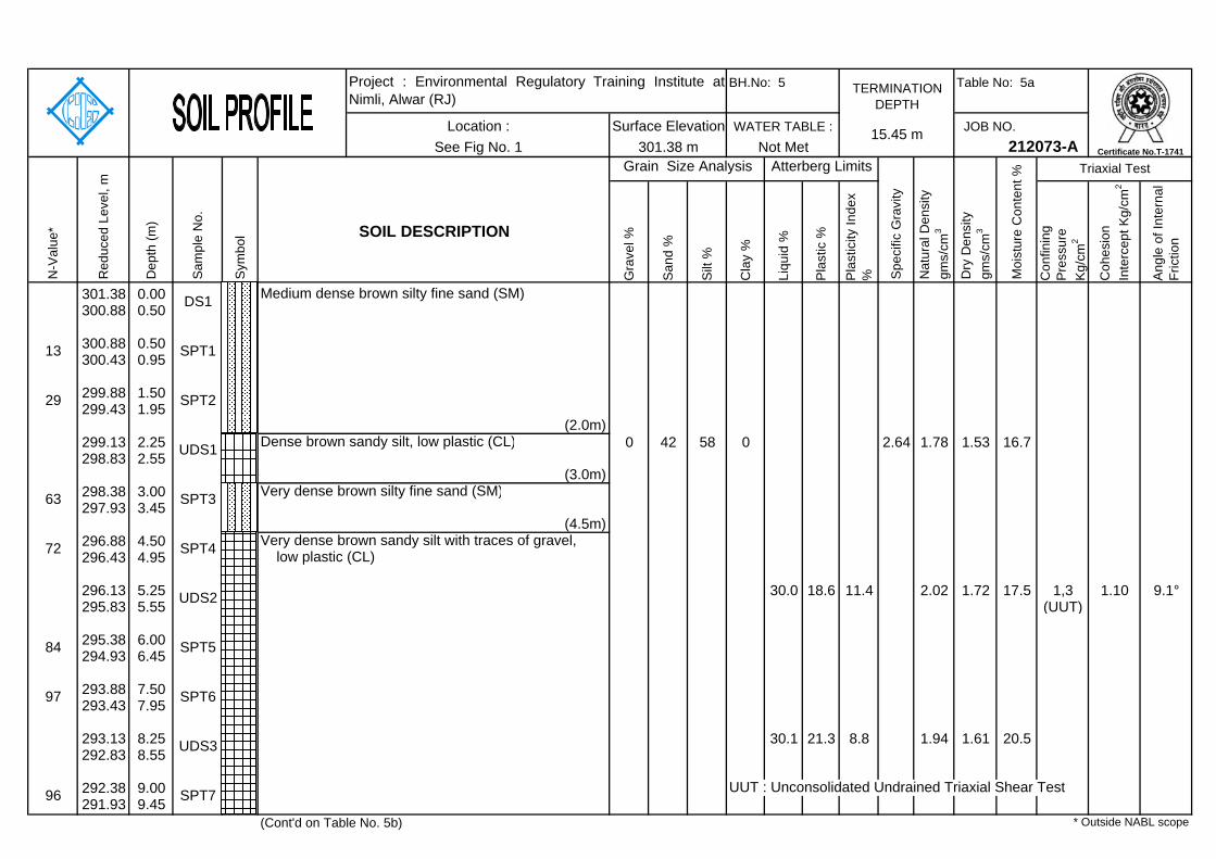
Table No: 5a
JOB NO.
Gra
vel %
San
d %
Silt
%
Cla
y %
Liqu
id %
Pla
stic
%
Pla
stic
ity In
dex
% Con
finin
g P
ress
ure
Kg/
cm2
Coh
esio
n In
terc
ept K
g/cm
2
Ang
le o
f Int
erna
l Fr
ictio
n
301.38 0.00300.88 0.50
300.88 0.50300.43 0.95
299.88 1.50299.43 1.95
299.13 2.25 0 42 58 0 2.64 1.78 1.53 16.7298.83 2.55
298.38 3.00297.93 3.45
296.88 4.50296.43 4.95
296.13 5.25 30.0 18.6 11.4 2.02 1.72 17.5 1,3 1.10 9.1°295.83 5.55 (UUT)
295.38 6.00294.93 6.45
293.88 7.50293.43 7.95
293.13 8.25 30.1 21.3 8.8 1.94 1.61 20.5292.83 8.55
292.38 9.00 UUT : Unconsolidated Undrained Triaxial Shear Test291.93 9.45
(Cont'd on Table No. 5b)
Sym
bol
N-V
alue
*
Red
uced
Lev
el, m
Dep
th (m
)
Sam
ple
No.
Project : Environmental Regulatory Training Institute atNimli, Alwar (RJ)
* Outside NABL scope
96 SPT7
UDS3
SOIL DESCRIPTION
(3.0m)
SPT4 Very dense brown sandy silt with traces of gravel, low plastic (CL)
(4.5m)
UDS2
Dense brown sandy silt, low plastic (CL)
SPT3
(2.0m)
Very dense brown silty fine sand (SM)
DS1
72
63
29 SPT2
13 SPT1
UDS1
84 SPT5
97 SPT6
212073-A
Medium dense brown silty fine sand (SM)
Moi
stur
e C
onte
nt % Triaxial Test
See Fig No. 115.45 m
Dry
Den
sity
gm
s/cm
3
Atterberg Limits
TERMINATION DEPTH
WATER TABLE :
Spe
cific
Gra
vity
Nat
ural
Den
sity
gm
s/cm
3
Grain Size Analysis
Surface Elevation301.38 m
BH.No: 5
Not MetLocation :
Certificate No.T-1741
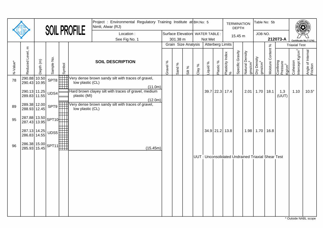
Table No: 5b
JOB NO.
Gra
vel %
San
d %
Silt
%
Cla
y %
Liqu
id %
Pla
stic
%
Pla
stic
ity In
dex
% Con
finin
g P
ress
ure
Kg/
cm2
Coh
esio
n In
terc
ept K
g/cm
2
Ang
le o
f Int
erna
l Fr
ictio
n
290.88 10.50290.43 10.95
290.13 11.25 39.7 22.3 17.4 2.01 1.70 18.1 1,3 1.10 10.5°289.83 11.55 (UUT)
289.38 12.00288.93 12.45
287.88 13.50287.43 13.95
287.13 14.25 34.9 21.2 13.8 1.98 1.70 16.8286.83 14.55
286.38 15.00285.93 15.45
UUT : Unconsolidated Undrained Triaxial Shear Test
N-V
alue
*
Red
uced
Lev
el, m
Dep
th (m
)
Sam
ple
No.
Sym
bol
Very dense brown sandy silt with traces of gravel,
SOIL DESCRIPTION
Grain Size Analysis
Location :301.38 m
Hard brown clayey silt with traces of gravel, medium plastic (MI)
low plastic (CL)(11.0m)
See Fig No. 1
(15.45m)
(12.0m)
WATER TABLE :
Project : Environmental Regulatory Training Institute atNimli, Alwar (RJ)
Surface Elevation
TERMINATION DEPTH
BH.No: 5
89 SPT9 Very dense brown sandy silt with traces of gravel, low plastic (CL)
UDS4
78 SPT8
95 SPT10
UDS5
96 SPT11
* Outside NABL scope
Moi
stur
e C
onte
nt %
Not Met 212073-A
Dry
Den
sity
gm
s/cm
3
Triaxial TestAtterberg Limits
Spe
cific
Gra
vity
15.45 m
Nat
ural
Den
sity
gm
s/cm
3
Certificate No.T-1741

Table No: 6a
JOB NO.
Gra
vel %
San
d %
Silt
%
Cla
y %
Liqu
id %
Pla
stic
%
Pla
stic
ity In
dex
% Con
finin
g P
ress
ure
Kg/
cm2
Coh
esio
n In
terc
ept K
g/cm
2
Ang
le o
f Int
erna
l Fr
ictio
n
302.50 0.00302.00 0.50
302.00 0.50301.55 0.95
301.00 1.50300.55 1.95
300.25 2.25 2 37 55 6 1.87 1.67 11.9 1,3 1.90 6.9°299.95 2.55 (UUT)
299.50 3.00299.05 3.45
298.00 4.50297.55 4.95
297.25 5.25 0 80 20 0 2.66 1.86 1.71 9.0296.95 5.55
296.50 6.00296.05 6.45
295.00 7.50294.55 7.95
294.25 8.25 4 43 49 4 1.79 1.70 5.6 1,3 2.00 7.5°293.95 8.55 (UUT)
293.50 9.00 UUT : Unconsolidated Undrained Triaxial Shear Test293.05 9.45
(Cont'd on Table No. 6b)
Sym
bol
N-V
alue
*
Red
uced
Lev
el, m
Dep
th (m
)
Sam
ple
No.
Project : Environmental Regulatory Training Institute atNimli, Alwar (RJ)
* Outside NABL scope
91 SPT7
UDS3
gravel (SM)
SOIL DESCRIPTION
(9.0m)Very dense brown silty fine sand with traces of
low plastic (CL)
SPT4
Very dense brown sandy silt with traces of gravel,
Very dense brown silty fine sand (SM)(5.0m)
UDS2
(6.0m)
Very dense brown sandy silt with traces of gravel, low plastic (CL)
SPT3
- dense, 0.0 to 1.5 m
(2.0m)
- very dense, 1.5 to 2.0 m
DS1
87
73
56 SPT2
41 SPT1
UDS1
76 SPT5
80 SPT6
212073-A
Dense to very dense brown silty fine sand (SM)
Moi
stur
e C
onte
nt % Triaxial Test
See Fig No. 115.45 m
Dry
Den
sity
gm
s/cm
3
Atterberg Limits
TERMINATION DEPTH
WATER TABLE :
Spe
cific
Gra
vity
Nat
ural
Den
sity
gm
s/cm
3
Grain Size Analysis
Surface Elevation302.50 m
BH.No: 6
Not MetLocation :
Certificate No.T-1741

Table No: 6b
JOB NO.
Gra
vel %
San
d %
Silt
%
Cla
y %
Liqu
id %
Pla
stic
%
Pla
stic
ity In
dex
% Con
finin
g P
ress
ure
Kg/
cm2
Coh
esio
n In
terc
ept K
g/cm
2
Ang
le o
f Int
erna
l Fr
ictio
n
292.00 10.50291.55 10.95
291.25 11.25 1 25 72 2 1.93 1.67 16.1290.95 11.55
290.50 12.00290.05 12.45
289.00 13.50288.55 13.95
288.25 14.25 38.2 20.1 18.1 1.99 1.77 12.3287.95 14.55
287.50 15.00287.05 15.45 low plastic (CL) (15.45m)
N-V
alue
*
Red
uced
Lev
el, m
Dep
th (m
)
Sam
ple
No.
Sym
bol
Very dense brown silty fine sand with traces of
SOIL DESCRIPTION
Grain Size Analysis
Location :302.50 m
Very dense brown sandy silt with traces of gravel, low plastic (CL)
gravel (SM)(11.0m)
plastic (MI)(15.0m)
See Fig No. 1
Very dense brown sandy silt with traces of gravel,
(14.0m)
WATER TABLE :
Project : Environmental Regulatory Training Institute atNimli, Alwar (RJ)
Surface Elevation
TERMINATION DEPTH
BH.No: 6
94 SPT9
UDS4
107 SPT8
105 SPT10
UDS5 Hard brown clayey silt with traces of gravel, medium
91 SPT11
* Outside NABL scope
Moi
stur
e C
onte
nt %
Not Met 212073-A
Dry
Den
sity
gm
s/cm
3
Triaxial TestAtterberg Limits
Spe
cific
Gra
vity
15.45 m
Nat
ural
Den
sity
gm
s/cm
3
Certificate No.T-1741

Table No: 7a
JOB NO.
Gra
vel %
San
d %
Silt
%
Cla
y %
Liqu
id %
Pla
stic
%
Pla
stic
ity In
dex
% Con
finin
g P
ress
ure
Kg/
cm2
Coh
esio
n In
terc
ept K
g/cm
2
Ang
le o
f Int
erna
l Fr
ictio
n
302.54 0.00302.04 0.50
302.04 0.50301.59 0.95
301.04 1.50300.59 1.95
300.29 2.25 0 80 20 0 1.78 1.67 6.8299.99 2.55
299.54 3.00299.09 3.45
298.04 4.50297.59 4.95
297.29 5.25 0 80 20 0 1.83 1.68 8.8 0.5 0 32.8°296.99 5.55 1.0
1.5296.54 6.00 (DS)296.09 6.45
295.04 7.50294.59 7.95
294.29 8.25 2 60 37 1 2.66 1.86 1.70 9.5293.99 8.55
DS : Drained Direct Shear Test293.54 9.00293.09 9.45
(Cont'd on Table No. 7b)
Sym
bol
N-V
alue
*
Red
uced
Lev
el, m
Dep
th (m
)
Sam
ple
No.
Project : Environmental Regulatory Training Institute atNimli, Alwar (RJ)
* Outside NABL scope
99 SPT7
UDS3
SOIL DESCRIPTION
SPT4 - very dense, 4.5 to 14.0 m
- with traces of gravel, 6.0 to 14.0 m
UDS2
SPT3
(SM) - medium dense, 0.0 to 1.5 m
- with traces of gravel, 3.0 to 5.0 m
- dense, 1.5 to 4.5 m
DS1
53
43
35 SPT2
17 SPT1
UDS1
74 SPT5
87 SPT6
212073-A
Medium dense to very dense brown silty fine sand
Moi
stur
e C
onte
nt % Triaxial Test
See Fig No. 115.45 m
Dry
Den
sity
gm
s/cm
3
Atterberg Limits
TERMINATION DEPTH
WATER TABLE :
Spe
cific
Gra
vity
Nat
ural
Den
sity
gm
s/cm
3
Grain Size Analysis
Surface Elevation302.54 m
BH.No: 7
Not MetLocation :
Certificate No.T-1741

Table No: 7b
JOB NO.
Gra
vel %
San
d %
Silt
%
Cla
y %
Liqu
id %
Pla
stic
%
Pla
stic
ity In
dex
% Con
finin
g P
ress
ure
Kg/
cm2
Coh
esio
n In
terc
ept K
g/cm
2
Ang
le o
f Int
erna
l Fr
ictio
n
292.04 10.50291.59 10.95
291.29 11.25 4 58 37 1 1.94 1.77 9.6 0.5 0 36.6°290.99 11.55 1.0
1.5290.54 12.00 (DS)290.09 12.45
289.04 13.50288.59 13.95
288.29 14.25 0 29 71 0 2.01 1.79 12.3287.99 14.55
287.54 15.00287.09 15.45
DS : Drained Direct Shear Test
N-V
alue
*
Red
uced
Lev
el, m
Dep
th (m
)
Sam
ple
No.
Sym
bol
Very dense brown silty fine sand with traces of
SOIL DESCRIPTION
Grain Size Analysis
Location :302.54 m
gravel (SM)
See Fig No. 1
- with traces of gravel, 15.0 to 15.45 m(15.45 m)
(14.0m)
WATER TABLE :
Project : Environmental Regulatory Training Institute atNimli, Alwar (RJ)
Surface Elevation
TERMINATION DEPTH
BH.No: 7
94 SPT9
UDS4
96 SPT8
103 SPT10
UDS5 Very dense brown sandy silt, low plastic (CL)
98 SPT11
* Outside NABL scope
Moi
stur
e C
onte
nt %
Not Met 212073-A
Dry
Den
sity
gm
s/cm
3
Triaxial TestAtterberg Limits
Spe
cific
Gra
vity
15.45 m
Nat
ural
Den
sity
gm
s/cm
3
Certificate No.T-1741
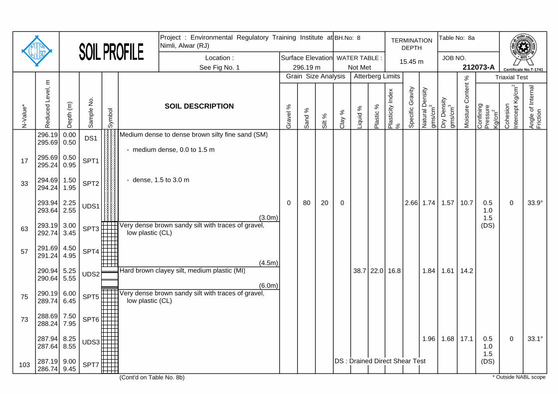
Table No: 8a
JOB NO.
Gra
vel %
San
d %
Silt
%
Cla
y %
Liqu
id %
Pla
stic
%
Pla
stic
ity In
dex
% Con
finin
g P
ress
ure
Kg/
cm2
Coh
esio
n In
terc
ept K
g/cm
2
Ang
le o
f Int
erna
l Fr
ictio
n
296.19 0.00295.69 0.50
295.69 0.50295.24 0.95
294.69 1.50294.24 1.95
293.94 2.25 0 80 20 0 2.66 1.74 1.57 10.7 0.5 0 33.9°293.64 2.55 1.0
1.5293.19 3.00 (DS)292.74 3.45
291.69 4.50291.24 4.95
290.94 5.25 38.7 22.0 16.8 1.84 1.61 14.2290.64 5.55
290.19 6.00289.74 6.45
288.69 7.50288.24 7.95
287.94 8.25 1.96 1.68 17.1 0.5 0 33.1°287.64 8.55 1.0
1.5287.19 9.00 DS : Drained Direct Shear Test (DS)286.74 9.45
(Cont'd on Table No. 8b)
Sym
bol
N-V
alue
*
Red
uced
Lev
el, m
Dep
th (m
)
Sam
ple
No.
Project : Environmental Regulatory Training Institute atNimli, Alwar (RJ)
* Outside NABL scope
103 SPT7
UDS3
SOIL DESCRIPTION
(3.0m)
low plastic (CL)
SPT4
Very dense brown sandy silt with traces of gravel,
low plastic (CL)
Hard brown clayey silt, medium plastic (MI)(4.5m)
UDS2
(6.0m)
SPT3
- medium dense, 0.0 to 1.5 m
Very dense brown sandy silt with traces of gravel,
- dense, 1.5 to 3.0 m
DS1
57
63
33 SPT2
17 SPT1
UDS1
75 SPT5
73 SPT6
212073-A
Medium dense to dense brown silty fine sand (SM)
Moi
stur
e C
onte
nt % Triaxial Test
See Fig No. 115.45 m
Dry
Den
sity
gm
s/cm
3
Atterberg Limits
TERMINATION DEPTH
WATER TABLE :
Spe
cific
Gra
vity
Nat
ural
Den
sity
gm
s/cm
3
Grain Size Analysis
Surface Elevation296.19 m
BH.No: 8
Not MetLocation :
Certificate No.T-1741
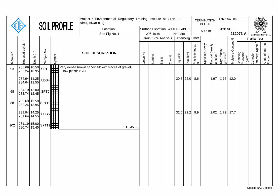
Table No: 8b
JOB NO.
Gra
vel %
San
d %
Silt
%
Cla
y %
Liqu
id %
Pla
stic
%
Pla
stic
ity In
dex
% Con
finin
g P
ress
ure
Kg/
cm2
Coh
esio
n In
terc
ept K
g/cm
2
Ang
le o
f Int
erna
l Fr
ictio
n
285.69 10.50285.24 10.95
284.94 11.25 30.6 22.0 8.6 1.97 1.76 12.0284.64 11.55
284.19 12.00283.74 12.45
282.69 13.50282.24 13.95
281.94 14.25 32.0 22.2 9.9 2.02 1.72 17.7281.64 14.55
281.19 15.00280.74 15.45
N-V
alue
*
Red
uced
Lev
el, m
Dep
th (m
)
Sam
ple
No.
Sym
bol
Very dense brown sandy silt with traces of gravel,
SOIL DESCRIPTION
Grain Size Analysis
Location :296.19 m
low plastic (CL)
See Fig No. 1
(15.45 m)
WATER TABLE :
Project : Environmental Regulatory Training Institute atNimli, Alwar (RJ)
Surface Elevation
TERMINATION DEPTH
BH.No: 8
98 SPT9
UDS4
93 SPT8
88 SPT10
UDS5
102 SPT11
* Outside NABL scope
Moi
stur
e C
onte
nt %
Not Met 212073-A
Dry
Den
sity
gm
s/cm
3
Triaxial TestAtterberg Limits
Spe
cific
Gra
vity
15.45 m
Nat
ural
Den
sity
gm
s/cm
3
Certificate No.T-1741
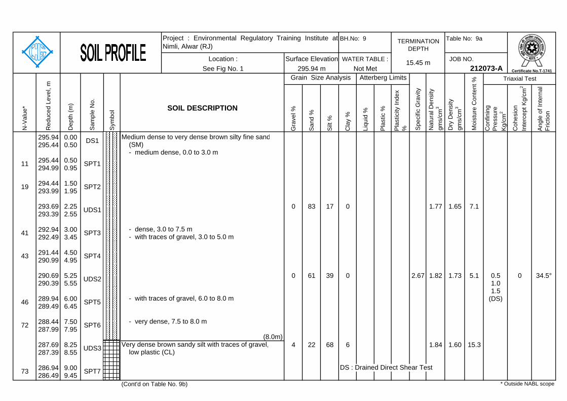
Table No: 9a
JOB NO.
Gra
vel %
San
d %
Silt
%
Cla
y %
Liqu
id %
Pla
stic
%
Pla
stic
ity In
dex
% Con
finin
g P
ress
ure
Kg/
cm2
Coh
esio
n In
terc
ept K
g/cm
2
Ang
le o
f Int
erna
l Fr
ictio
n
295.94 0.00295.44 0.50
295.44 0.50294.99 0.95
294.44 1.50293.99 1.95
293.69 2.25 0 83 17 0 1.77 1.65 7.1293.39 2.55
292.94 3.00292.49 3.45
291.44 4.50290.99 4.95
290.69 5.25 0 61 39 0 2.67 1.82 1.73 5.1 0.5 0 34.5°290.39 5.55 1.0
1.5289.94 6.00 (DS)289.49 6.45
288.44 7.50287.99 7.95
287.69 8.25 4 22 68 6 1.84 1.60 15.3287.39 8.55
286.94 9.00 DS : Drained Direct Shear Test286.49 9.45
(Cont'd on Table No. 9b)
Sym
bol
N-V
alue
*
Red
uced
Lev
el, m
Dep
th (m
)
Sam
ple
No.
Project : Environmental Regulatory Training Institute atNimli, Alwar (RJ)
Very dense brown sandy silt with traces of gravel,
* Outside NABL scope
73 SPT7
UDS3
SOIL DESCRIPTION
(8.0m)
low plastic (CL)
SPT4
- with traces of gravel, 6.0 to 8.0 m
- with traces of gravel, 3.0 to 5.0 m
UDS2
- very dense, 7.5 to 8.0 m
SPT3
(SM) - medium dense, 0.0 to 3.0 m
- dense, 3.0 to 7.5 m
DS1
43
41
19 SPT2
11 SPT1
UDS1
46 SPT5
72 SPT6
212073-A
Medium dense to very dense brown silty fine sand
Moi
stur
e C
onte
nt % Triaxial Test
See Fig No. 115.45 m
Dry
Den
sity
gm
s/cm
3
Atterberg Limits
TERMINATION DEPTH
WATER TABLE :
Spe
cific
Gra
vity
Nat
ural
Den
sity
gm
s/cm
3
Grain Size Analysis
Surface Elevation295.94 m
BH.No: 9
Not MetLocation :
Certificate No.T-1741

Table No: 9b
JOB NO.
Gra
vel %
San
d %
Silt
%
Cla
y %
Liqu
id %
Pla
stic
%
Pla
stic
ity In
dex
% Con
finin
g P
ress
ure
Kg/
cm2
Coh
esio
n In
terc
ept K
g/cm
2
Ang
le o
f Int
erna
l Fr
ictio
n
285.44 10.50284.99 10.95
284.69 11.25 34.7 20.5 14.2 2.15 1.87 15.2 1,3 1.90 7.4°284.39 11.55 (UUT)
283.94 12.00283.49 12.45
282.44 13.50281.99 13.95
281.69 14.25 34.7 16.2 18.5 2.01 1.75 15.0281.39 14.55
280.94 15.00280.49 15.45
UUT : Unconsolidated Undrained Triaxial Shear Test
N-V
alue
*
Red
uced
Lev
el, m
Dep
th (m
)
Sam
ple
No.
Sym
bol
Very dense brown sandy silt with traces of gravel,
SOIL DESCRIPTION
Grain Size Analysis
Location :295.94 m
low plastic (CL)
See Fig No. 1
(15.45 m)
WATER TABLE :
Project : Environmental Regulatory Training Institute atNimli, Alwar (RJ)
Surface Elevation
TERMINATION DEPTH
BH.No: 9
37 SPT9
UDS4
63 SPT8
57 SPT10
UDS5
52 SPT11
* Outside NABL scope
Moi
stur
e C
onte
nt %
Not Met 212073-A
Dry
Den
sity
gm
s/cm
3
Triaxial TestAtterberg Limits
Spe
cific
Gra
vity
15.45 m
Nat
ural
Den
sity
gm
s/cm
3
Certificate No.T-1741

Table No: 10a
JOB NO.
Gra
vel %
San
d %
Silt
%
Cla
y %
Liqu
id %
Pla
stic
%
Pla
stic
ity In
dex
% Con
finin
g P
ress
ure
Kg/
cm2
Coh
esio
n In
terc
ept K
g/cm
2
Ang
le o
f Int
erna
l Fr
ictio
n
294.29 0.00293.79 0.50
293.79 0.50293.34 0.95
292.79 1.50292.34 1.95
292.04 2.25 3 22 73 2 1.76 1.49 17.8291.74 2.55
291.29 3.00290.84 3.45
289.79 4.50289.34 4.95
289.04 5.25 9 22 68 1 2.67 1.94 1.68 15.2288.74 5.55
288.29 6.00287.84 6.45
286.79 7.50286.34 7.95
286.04 8.25 4 69 26 1 1.86 1.61 15.6 0.5 0 34.2°285.74 8.55 1.0
1.5285.29 9.00 DS : Drained Direct Shear Test (DS)284.84 9.45
(Cont'd on Table No. 10b)
Sym
bol
N-V
alue
*
Red
uced
Lev
el, m
Dep
th (m
)
Sam
ple
No.
Project : Environmental Regulatory Training Institute atNimli, Alwar (RJ)
* Outside NABL scope
82 SPT7
UDS3
low plastic (CL)
SOIL DESCRIPTION
(9.0m)Very dense brown sandy silt with traces of gravel,
(3.0m)
gravel (SM)
SPT4 Very dense brown sandy silt with gravel, low plastic
Very dense brown silty fine sand with traces of
(CL)
(4.5m)
UDS2
(6.0m)
Medium dense brown sandy silt with traces of gravel, low plastic (CL)
SPT3
(2.0m)
Medium dense brown silty fine sand (SM)
DS1
91
27
24 SPT2
20 SPT1
UDS1
74 SPT5
60 SPT6
212073-A
Medium dense brown silty fine sand (SM)
Moi
stur
e C
onte
nt % Triaxial Test
See Fig No. 115.45 m
Dry
Den
sity
gm
s/cm
3
Atterberg Limits
TERMINATION DEPTH
WATER TABLE :
Spe
cific
Gra
vity
Nat
ural
Den
sity
gm
s/cm
3
Grain Size Analysis
Surface Elevation294.29 m
BH.No: 10
Not MetLocation :
Certificate No.T-1741

Table No: 10b
JOB NO.
Gra
vel %
San
d %
Silt
%
Cla
y %
Liqu
id %
Pla
stic
%
Pla
stic
ity In
dex
% Con
finin
g P
ress
ure
Kg/
cm2
Coh
esio
n In
terc
ept K
g/cm
2
Ang
le o
f Int
erna
l Fr
ictio
n
283.79 10.50283.34 10.95
283.04 11.25 29.6 18.8 10.9 1.97 1.77 11.6282.74 11.55
282.29 12.00281.84 12.45
280.79 13.50280.34 13.95
280.04 14.25279.74 14.55
279.29 15.00278.84 15.45
N-V
alue
*
Red
uced
Lev
el, m
Dep
th (m
)
Sam
ple
No.
Sym
bol
Very dense brown sandy silt with traces of gravel,
SOIL DESCRIPTION
Grain Size Analysis
Location :294.29 m
(13.5m)
low plastic (CL)
See Fig No. 1
(15.45 m)
WATER TABLE :
Project : Environmental Regulatory Training Institute atNimli, Alwar (RJ)
Surface Elevation
TERMINATION DEPTH
BH.No: 10
108 SPT9
UDS4
83 SPT8
53 SPT10 Very dense brown silty fine sand with traces of gravel (SM)
UDS5
68 SPT1
* Outside NABL scope
Moi
stur
e C
onte
nt %
Not Met 212073-A
Dry
Den
sity
gm
s/cm
3
Triaxial TestAtterberg Limits
Spe
cific
Gra
vity
15.45 m
Nat
ural
Den
sity
gm
s/cm
3
Certificate No.T-1741

Borehole No.
Depth, (m)
1 2.25
2 5.25
3 2.25
5 5.25
6 2.25
7 5.25
8 2.25
9 5.25
10 2.25
12345
NegligibleModerate
High
Very High
*SOURCE : INSTITUTION OF CIVIL ENGINEERS, LONDON (1979)
0.10 0.02 8.5
0.10 0.03 8.4
0.11 0.04 8.3
0.09 0.01 8.3
8.3
0.10 0.03 8.4
CENGRS GEOTECHNICA PVT. LTD. Job No. 212073-A Fig No. 11
SOIL-WATER EXTRACT :
0.03
0.02
0.03
0.09 0.02
Chemical Test Results
8.4
Less than 300
Environmental Regulatory Training Institute at Nimli, Alwar (RJ)
Sulphate Content (SO3), %
Chloride Content, %
0.11
0.10
0.10
pH Value
8.2
8.3
0.5 to 1.0
REQUIREMENTS FOR CONCRETE EXPOSED TO SULPHATE ATTACK AS PER IS : 456-2000, CLAUSES 8.2.2.4 AND 9.1.2, TABLE 4, PAGE-19
Class In Groundwater (mg/l)
Traces (<0.2)300-1200
1200-2500
ClassificationTropical Climate
CLASSIFICATION OF CHLORIDE CONDITIONS IN GROUNDWATER*
1.0 to 2.0> 2.0
2500-5000> 5000
Temperate ClimateChloride Limits
Generally not applicable
More than 10,000 ppm2000-10,000 ppm 0-2000 ppm
2000-20,000 ppmOnly if considerably in excess of
20,000 ppm
Not Applicable
0.2 to 0.5
0-2000 ppm
Concentration of Sulphates, expressed as SO3
In-Soil-Water Extract (Total) Percent

SPT (N) Value
SPT (N) Value
0 to 2 0 to 4
2 to 4 4 to 10
4 to 8 10 to 30
8 to 15 30 to 50
15 to 30
> 30
Degree of Expansion
Low
Medium
High
Very High
ENGINEERING DESCRIPTION OF SOILS
PLASTICITY OF CLAY
CENGRS GEOTECHNICA PVT. LTD.
< 15
15 -30
30 - 60
> 60
< 12
12 - 23
DEGREE OF EXPANSION OF FINE GRAINED SOILS
Non-critical
Marginal
Critical
Severe
< 50
50 -100
100 - 200
> 200
23 - 32
> 3270 - 90
50 - 70
35 - 50
20 - 35
Liquid Limit Plasticity Index Shrinkage Index Free Swell Percent Degree of Severity
Job No.: 212073-A Table No. 12
Very dense > 50
Very Loose
Loose
Medium Dense
DENSITY CONDITION OF GRANULAR SOILS
Medium Plastic
Consistency Cohesion Intercept, kg/sq.cm Density Descriptor
Static Cone Tip Resistance kg/sq.cm
Low Plastic
> 50
35 to 50
< 35
High Plastic
0.5 to 1.0
1.0 to 2.0
> 2.0
Plasticity Liquid Limit
CONSISTENCY OF COHESIVE SOILS
Firm/Medium
Soft
Hard
Very Stiff
Stiff
Very Soft < 0.1
0.1 to 0.25
0.25 to 0.5
Dense
> 200
< 20
20 to 40
40 to 120
120 to 200

NABL ACCREDITED LABORATORY Our laboratory is accredited to National Accreditation Board for Testing and Calibration Laboratories (NABL), New Delhi. The quality procedures in our laboratory conform to the International Standard ISO/IEC: 17025-2005. The accreditation assures our clients of work quality in conformance with international norms and practices. It authorizes us to use the NABL logo on test results. To maintain the necessary level of quality and reliability in all measurements on a continual basis, we indulge in the following:
Use of calibrated equipment, regular maintenance and good housekeeping are a part of our work culture.
Inter-laboratory comparison, proficiency testing and replicate testing, continuing education - ensure uniform quality of results.
Internal Audit of quality procedures is done by our qualified ISO 17025 auditors to maintain the requisite standards. NABL conducts external audit.
UNCERTAINTY Every measurement entails an uncertainty. It is well known that no measuring instrument can determine the true value of any measurement. The cumulative effect of factors such as sensitivity of equipment, accuracy in calibration, human factors and environmental conditions will determine the overall uncertainty in the parameter determined from these measurements. As a part of our commitment to our clients, we have worked out the uncertainty in the parameters reported by our laboratory. Although this does not form a part of our contract agreement, we present below our statistical estimate of uncertainty of various parameters based on our most recent evaluation (Feb., 2012).
Test / Parameter Uncertainty* Test / Parameter Uncertainty* Moisture Content ± 0.26 % Free Swell Index, % ± 2.20 %
Bulk & Dry Density ± 0.004 g/cc Swell Pressure ± 0.43 % Specific Gravity ± 0.08 cc1 ± 0.0003
Liquid Limit ± 0.59 % cc2 ± 0.003 Plastic Limit ± 0.27 % mv ± 0.0003 cm2/kg
Shrinkage Limit ± 0.26 %
Consolidation
pc ± 0.15 kg/cm2 Unconfined
Compression c ± 0.185 kg/cm2 CD Direct Shear Test φ ± 0.61°
c ± 0.09 kg/cm2 Coarse grained soils ± 0.8% of particle size UU Triaxial
Test φ ± 0.5°
Soil Gradation Fine grained
soils ± 1.5% of particle size
MDD ± 0.03 g/cc Coefficient of Permeability ± 1.3 % of value Std/Mod
Proctor Compaction OMC ± 0.26 % Crushing
Strength ± 0.80 % of value
Laboratory CBR ± 0.31% Rock Point Load
Strength Index
± 0.1 % of value
* at 95 percent confidence level for coverage factor of 2
UNCERTAINTY IN LABORATORY MEASUREMENTS
Table No: 13 Job No. 212073-A


SYMBOL
Pebbles and gravels (SM-GP)Gravel mixed with sand (GP-SP-SM)
Environmental Regulatory Training Institute at Nimli, Alwar (RJ)Summary of Borehole Profiles
Silty fine sand (SM)
Rock
LEGEND
CENGRS GEOTECHNICA PVT. LTD. Job.No.: 212073-A Fig No.: 2a
DESCRIPTIONSandy silt (CL)
R E
D U
C E
D L
E V
E L
, m
302
298
294
290
286
282
*Ref' refers to refusal (N>100) within the first 15 cm of seating penetration.
278
274
270
N-Value
BH-1RL: 289.50 m
15.45m
2843
56
78
53
61
42
65
61
43
52
5.06.0
11.0
N-Value
BH-2RL:289.11 m
15.45m
1523
26
21
33
43
49
51
36
45
56
11.0
8.09.0
N-Value
15.45m
1329
63
72
84
97
96
78
89
95
96
BH-5RL: 301.38 m
2.03.0
4.5
11.012.0
N-Value
BH-4RL: 301.28 m
3.10 m
1224
Ref*/ 10cm3.02.0
N-Value
BH-3RL: 291.76 m
15.45m
1817
14
11
9
17
71
79
54
58
78
5.0
6.0
9.0
14.015.0

SYMBOL
Summary of Borehole Profiles
CENGRS GEOTECHNICA PVT. LTD. Job.No.: 212073-A Fig No.: 2b
LEGENDDESCRIPTION
Sandy silt (CL)Silty fine sand (SM)Clayey silt (MI)
Environmental Regulatory Training Institute at Nimli, Alwar (RJ)
R E
D U
C E
D L
E V
E L
, m
304
300
296
292
288
284
280
276
272
N-Value
BH-7RL: 302.54 m
15.45m
1735
43
53
74
87
99
96
94
103
98
14.0
N-Value
BH-9RL: 295.94 m
15.45m
1119
41
43
46
72
73
63
37
57
52
8.0
N-Value
BH-10RL: 294.29 m
15.45m
2024
27
91
74
60
82
83
108
53
68
2.03.0
4.5
6.0
9.0
13.5
N-Value
BH-8RL: 296.19 m
15.45m
1733
63
57
75
73
103
93
98
88
102
3.0
4.5
6.0
N-Value
BH-6RL: 302.50 m
15.45m
4156
73
87
76
80
91
107
94
105
91
6.05.0
2.0
9.0
11.0
14.015.0

Symbol BH.No.123 45
Environmental Regulatory Training Institute at Nimli, Alwar (RJ)
291.760301.282301.384
Standard Penetration Test Results (Field Values)
Fig No. 3aJob No. 212073-ACENGRS GEOTECHNICA PVT. LTD.
L E G E N DReduced Level,m
289.504289.111
STANDARD PENETRATION TEST
272
274
276
278
280
282
284
286
288
290
292
294
296
298
300
3020 10 20 30 40 50 60 70 80 90 100 110
S P T F I E L D V A L U E (N)
R E
D U
C E
D L
E V
E L
, m
Ref/10cm
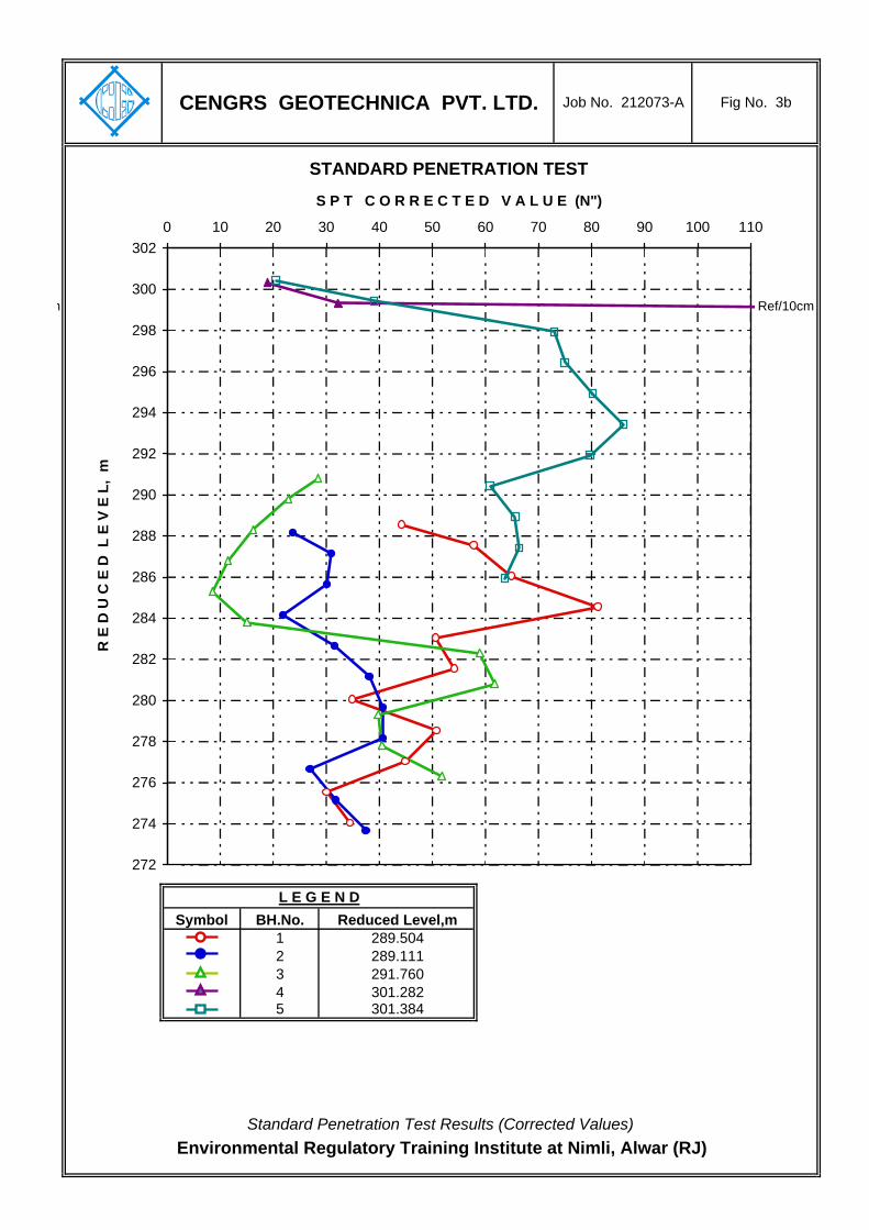
Symbol BH.No.123 45
Environmental Regulatory Training Institute at Nimli, Alwar (RJ)Standard Penetration Test Results (Corrected Values)
291.760301.282301.384
L E G E N DReduced Level,m
289.504289.111
CENGRS GEOTECHNICA PVT. LTD. Job No. 212073-A Fig No. 3b
STANDARD PENETRATION TEST
272
274
276
278
280
282
284
286
288
290
292
294
296
298
300
3020 10 20 30 40 50 60 70 80 90 100 110
S P T C O R R E C T E D V A L U E (N")
R E
D U
C E
D L
E V
E L
, m
m Ref/10cm

Symbol BH.No.678 910
L E G E N DReduced Level,m
302.498302.540
Fig No. 3cJob No. 212073-ACENGRS GEOTECHNICA PVT. LTD.
Environmental Regulatory Training Institute at Nimli, Alwar (RJ)
296.189295.942294.288
Standard Penetration Test Results (Field Values)
STANDARD PENETRATION TEST
276
278
280
282
284
286
288
290
292
294
296
298
300
302
3040 10 20 30 40 50 60 70 80 90 100 110 120
S P T F I E L D V A L U E (N)
R E
D U
C E
D L
E V
E L
, m

Symbol BH.No.678 910
CENGRS GEOTECHNICA PVT. LTD. Job No. 212073-A Fig No. 3d
L E G E N DReduced Level,m
302.498302.540296.189295.942294.288
Environmental Regulatory Training Institute at Nimli, Alwar (RJ)Standard Penetration Test Results (Corrected Values)
STANDARD PENETRATION TEST
276
278
280
282
284
286
288
290
292
294
296
298
300
302
3040 10 20 30 40 50 60 70 80 90 100 110 120
S P T C O R R E C T E D V A L U E (N")
R E
D U
C E
D L
E V
E L
, m

Borehole Number
Sample Depth, m
% Gravel
% Sand % Silt % Clay D60 D10 Cu
BH-1 2.25 3 74 23 0 0.131 0.088 1.5
BH-1 5.25 2 21 75 2 0.075 0.012 6.5
BH-1 8.25 0 74 26 0 0.150 0.075 2.0
BH-1 11.25 0 44 56 0 0.150 0.011 13.2
LABORATORY: CENGRS GEOTECHNICA PVT. LTD.
An ISO /IEC: 17025-2005 accredited Laboratory
Fig. No. 4Job No.: 212073-A
Grain Size Analysis : IS : 2720 (Part 4) - 1985
Silty fine sand with traces of gravel (SM)
Sandy silt with traces of gravel (CL)
Silty fine sand (SM)
Sandy silt (CL)
TEST RESULTSSAMPLE DETAILS
Sample Description
Environmental Regulatory Training Institute at Nimli, Alwar (RJ)
0
10
20
30
40
50
60
70
80
90
100
0.001 0.010 0.100 1.000 10.000Particle Size, mm
% F
iner
by
Wei
ght
Borehole No: 1 , Depth: 2.25 m
Borehole No: 1 , Depth: 5.25 m
Borehole No: 1 , Depth: 8.25 m
Borehole No: 1 , Depth: 11.25 m
GRAVELCOARSEFINE MEDIUM
S A N DS I L TCLAY
Hydrometer Analysis Sieve Analysis
Certificate No.T-1741

Borehole Number
Sample Depth, m
% Gravel
% Sand % Silt % Clay D60 D10 Cu
BH-2 2.25 0 69 30 1 0.180 0.053 3.4
BH-2 5.25 0 80 20 0 0.150
BH-2 11.25 2 21 75 2 0.075 0.015 4.9
LABORATORY: CENGRS GEOTECHNICA PVT. LTD.
An ISO /IEC: 17025-2005 accredited Laboratory
Fig. No. 5Job No.: 212073-A
Grain Size Analysis : IS : 2720 (Part 4) - 1985
Silty fine sand (SM)
Silty fine sand (SM)
Sandy silt with traces of gravel (CL)
TEST RESULTSSAMPLE DETAILS
Sample Description
Environmental Regulatory Training Institute at Nimli, Alwar (RJ)
0
10
20
30
40
50
60
70
80
90
100
0.001 0.010 0.100 1.000 10.000Particle Size, mm
% F
iner
by
Wei
ght
Borehole No: 2 , Depth: 2.25 m
Borehole No: 2 , Depth: 5.25 m
Borehole No: 2 , Depth: 11.25 m
GRAVELCOARSEFINE MEDIUM
S A N DS I L TCLAY
Hydrometer Analysis Sieve Analysis
Certificate No.T-1741
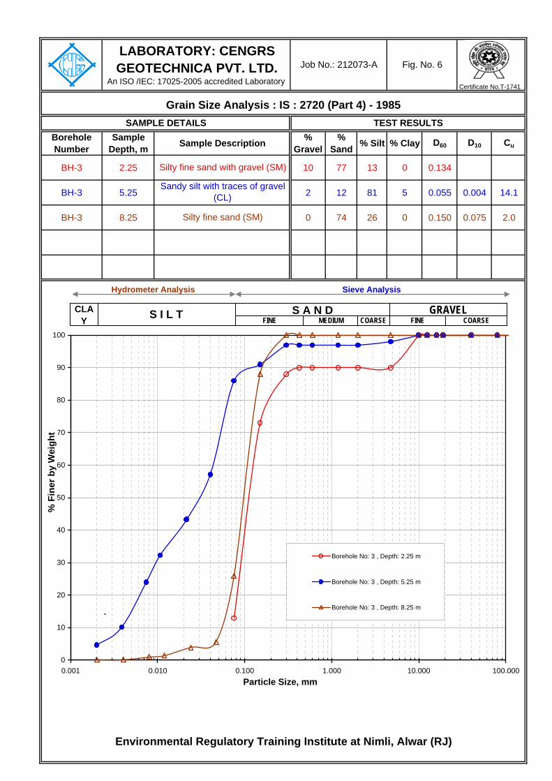
Borehole Number
Sample Depth, m
% Gravel
% Sand % Silt % Clay D60 D10 Cu
BH-3 2.25 10 77 13 0 0.134
BH-3 5.25 2 12 81 5 0.055 0.004 14.1
BH-3 8.25 0 74 26 0 0.150 0.075 2.0
LABORATORY: CENGRS GEOTECHNICA PVT. LTD.
An ISO /IEC: 17025-2005 accredited Laboratory
Fig. No. 6Job No.: 212073-A
Grain Size Analysis : IS : 2720 (Part 4) - 1985
Silty fine sand with gravel (SM)
Sandy silt with traces of gravel (CL)
Silty fine sand (SM)
TEST RESULTSSAMPLE DETAILS
Sample Description
Environmental Regulatory Training Institute at Nimli, Alwar (RJ)
0
10
20
30
40
50
60
70
80
90
100
0.001 0.010 0.100 1.000 10.000 100.000Particle Size, mm
% F
iner
by
Wei
ght
Borehole No: 3 , Depth: 2.25 m
Borehole No: 3 , Depth: 5.25 m
Borehole No: 3 , Depth: 8.25 m
Hydrometer Analysis Sieve Analysis
GRAVELFINE MEDIUMS I L T COARSE
S A N DCLAY FINE COARSE
Certificate No.T-1741
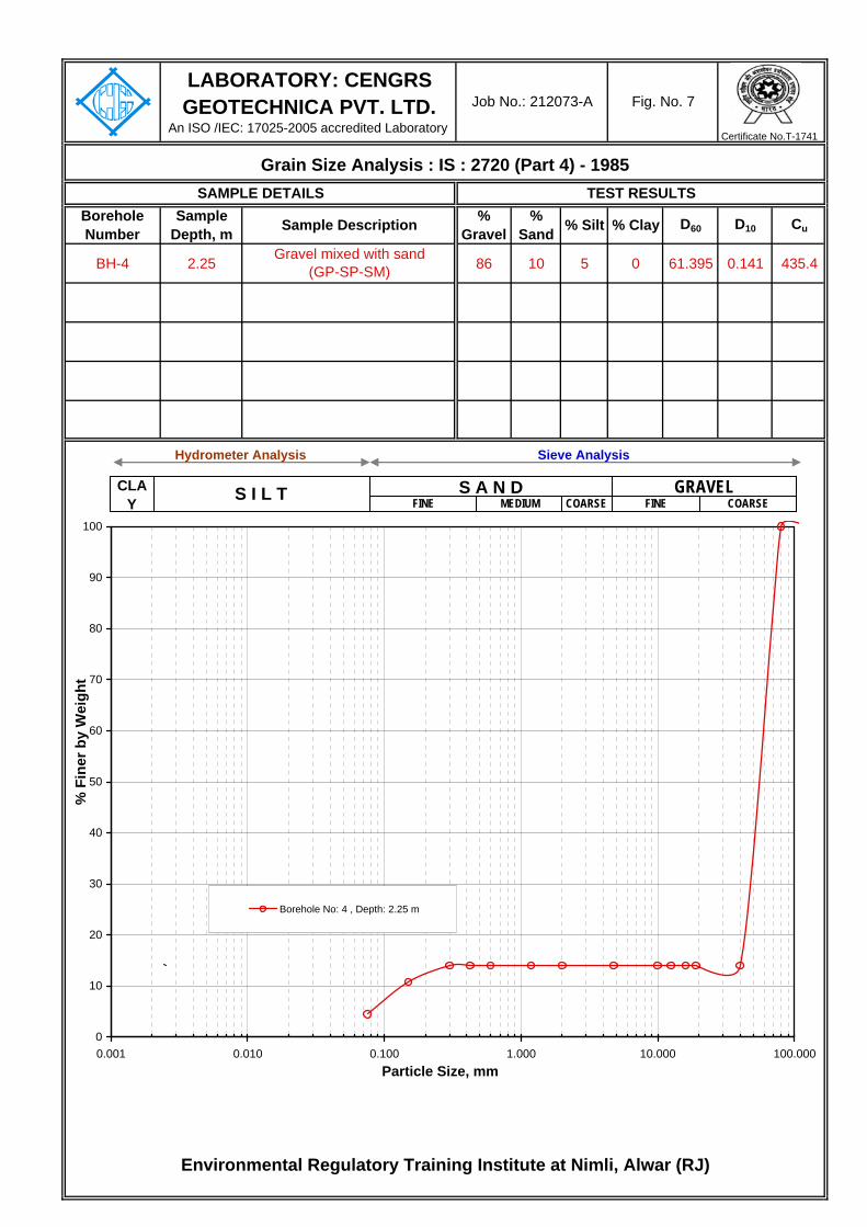
Borehole Number
Sample Depth, m
% Gravel
% Sand % Silt % Clay D60 D10 Cu
BH-4 2.25 86 10 5 0 61.395 0.141 435.4
LABORATORY: CENGRS GEOTECHNICA PVT. LTD.
An ISO /IEC: 17025-2005 accredited Laboratory
Fig. No. 7Job No.: 212073-A
Grain Size Analysis : IS : 2720 (Part 4) - 1985
Gravel mixed with sand (GP-SP-SM)
TEST RESULTSSAMPLE DETAILS
Sample Description
Environmental Regulatory Training Institute at Nimli, Alwar (RJ)
0
10
20
30
40
50
60
70
80
90
100
0.001 0.010 0.100 1.000 10.000 100.000Particle Size, mm
% F
iner
by
Wei
ght
Borehole No: 4 , Depth: 2.25 m
Certificate No.T-1741
Hydrometer Analysis Sieve Analysis
GRAVELFINE MEDIUMS I L T COARSE
S A N DCLAY FINE COARSE

Borehole Number
Sample Depth, m
% Gravel
% Sand % Silt % Clay D60 D10 Cu
BH-5 2.25 0 42 58 0 0.080 0.010 8.0
LABORATORY: CENGRS GEOTECHNICA PVT. LTD.
An ISO /IEC: 17025-2005 accredited Laboratory
Fig. No. 8Job No.: 212073-A
Grain Size Analysis : IS : 2720 (Part 4) - 1985
Sandy silt (CL)
TEST RESULTSSAMPLE DETAILS
Sample Description
Environmental Regulatory Training Institute at Nimli, Alwar (RJ)
0
10
20
30
40
50
60
70
80
90
100
0.001 0.010 0.100 1.000 10.000Particle Size, mm
% F
iner
by
Wei
ght
Borehole No: 5 , Depth: 2.25 m
GRAVELCOARSEFINE MEDIUM
S A N DS I L TCLAY
Hydrometer Analysis Sieve Analysis
Certificate No.T-1741
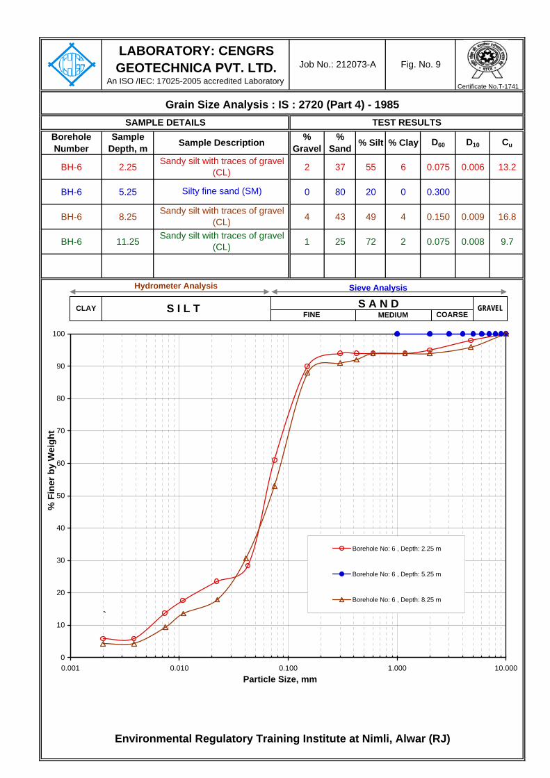
Borehole Number
Sample Depth, m
% Gravel
% Sand % Silt % Clay D60 D10 Cu
BH-6 2.25 2 37 55 6 0.075 0.006 13.2
BH-6 5.25 0 80 20 0 0.300
BH-6 8.25 4 43 49 4 0.150 0.009 16.8
BH-6 11.25 1 25 72 2 0.075 0.008 9.7
LABORATORY: CENGRS GEOTECHNICA PVT. LTD.
An ISO /IEC: 17025-2005 accredited Laboratory
Fig. No. 9Job No.: 212073-A
Grain Size Analysis : IS : 2720 (Part 4) - 1985
Sandy silt with traces of gravel (CL)
Silty fine sand (SM)
Sandy silt with traces of gravel (CL)
Sandy silt with traces of gravel (CL)
TEST RESULTSSAMPLE DETAILS
Sample Description
Environmental Regulatory Training Institute at Nimli, Alwar (RJ)
0
10
20
30
40
50
60
70
80
90
100
0.001 0.010 0.100 1.000 10.000Particle Size, mm
% F
iner
by
Wei
ght
Borehole No: 6 , Depth: 2.25 m
Borehole No: 6 , Depth: 5.25 m
Borehole No: 6 , Depth: 8.25 m
GRAVELCOARSEFINE MEDIUM
S A N DS I L TCLAY
Hydrometer Analysis Sieve Analysis
Certificate No.T-1741

Borehole Number
Sample Depth, m
% Gravel
% Sand % Silt % Clay D60 D10 Cu
BH-7 2.25 0 80 20 0 0.125
BH-7 5.25 0 80 20 0 0.150
BH-7 8.25 2 60 37 1 0.150 0.011 13.5
BH-7 11.25 4 58 37 1 0.150 0.015 10.3
BH-7 14.25 0 29 71 0 0.075 0.015 4.9
LABORATORY: CENGRS GEOTECHNICA PVT. LTD.
An ISO /IEC: 17025-2005 accredited Laboratory
Fig. No. 10Job No.: 212073-A
Grain Size Analysis : IS : 2720 (Part 4) - 1985
Sandy silt (CL)
Silty fine sand (SM)
Silty fine sand (SM)
Silty fine sand with traces of gravel (SM)
Silty fine sand with traces of gravel (SM)
TEST RESULTSSAMPLE DETAILS
Sample Description
Environmental Regulatory Training Institute at Nimli, Alwar (RJ)
0
10
20
30
40
50
60
70
80
90
100
0.001 0.010 0.100 1.000 10.000Particle Size, mm
% F
iner
by
Wei
ght
Borehole No: 7 , Depth: 2.25 m
Borehole No: 7 , Depth: 5.25 m
Borehole No: 7 , Depth: 8.25 m
Borehole No: 7 , Depth: 11.25 m
Borehole No: 7 , Depth: 14.25 m
GRAVELCOARSEFINE MEDIUM
S A N DS I L TCLAY
Hydrometer Analysis Sieve Analysis
Certificate No.T-1741

Borehole Number
Sample Depth, m
% Gravel
% Sand % Silt % Clay D60 D10 Cu
BH-8 2.25 0 80 20 0 0.123
LABORATORY: CENGRS GEOTECHNICA PVT. LTD.
An ISO /IEC: 17025-2005 accredited Laboratory
Fig. No. 11Job No.: 212073-A
Grain Size Analysis : IS : 2720 (Part 4) - 1985
Silty fine sand (SM)
TEST RESULTSSAMPLE DETAILS
Sample Description
Environmental Regulatory Training Institute at Nimli, Alwar (RJ)
0
10
20
30
40
50
60
70
80
90
100
0.001 0.010 0.100 1.000 10.000Particle Size, mm
% F
iner
by
Wei
ght
Borehole No: 8 , Depth: 2.25 m
GRAVELCOARSEFINE MEDIUM
S A N DS I L TCLAY
Hydrometer Analysis Sieve Analysis
Certificate No.T-1741

Borehole Number
Sample Depth, m
% Gravel
% Sand % Silt % Clay D60 D10 Cu
BH-9 2.25 0 83 17 0 0.122
BH-9 5.25 0 61 39 0 0.150 0.032 4.6
BH-9 8.25 4 22 68 6 0.075 0.004 19.6
LABORATORY: CENGRS GEOTECHNICA PVT. LTD.
An ISO /IEC: 17025-2005 accredited Laboratory
Fig. No. 12Job No.: 212073-A
Grain Size Analysis : IS : 2720 (Part 4) - 1985
Silty fine sand (SM)
Silty fine sand (SM)
Sandy silt with traces of gravel (CL)
TEST RESULTSSAMPLE DETAILS
Sample Description
Environmental Regulatory Training Institute at Nimli, Alwar (RJ)
0
10
20
30
40
50
60
70
80
90
100
0.001 0.010 0.100 1.000 10.000Particle Size, mm
% F
iner
by
Wei
ght
Borehole No: 9 , Depth: 2.25 m
Borehole No: 9 , Depth: 5.25 m
Borehole No: 9 , Depth: 8.25 m
GRAVELCOARSEFINE MEDIUM
S A N DS I L TCLAY
Hydrometer Analysis Sieve Analysis
Certificate No.T-1741

Borehole Number
Sample Depth, m
% Gravel
% Sand % Silt % Clay D60 D10 Cu
BH-10 2.25 3 22 73 2 0.078 0.005 14.3
BH-10 5.25 9 22 68 1 0.075 0.009 8.3
BH-10 8.25 4 69 26 1 0.150 0.063 2.4
LABORATORY: CENGRS GEOTECHNICA PVT. LTD.
An ISO /IEC: 17025-2005 accredited Laboratory
Fig. No. 13Job No.: 212073-A
Grain Size Analysis : IS : 2720 (Part 4) - 1985
Sandy silt with traces of gravel (CL)
Sandy silt with gravel (CL)
Silty fine sand with traces of gravel (SM)
TEST RESULTSSAMPLE DETAILS
Sample Description
Environmental Regulatory Training Institute at Nimli, Alwar (RJ)
0
10
20
30
40
50
60
70
80
90
100
0.001 0.010 0.100 1.000 10.000 100.000Particle Size, mm
% F
iner
by
Wei
ght
Borehole No: 10 , Depth: 2.25 m
Borehole No: 10 , Depth: 5.25 m
Borehole No: 10 , Depth: 8.25 m
Certificate No.T-1741
Hydrometer Analysis Sieve Analysis
GRAVELFINE MEDIUMS I L T COARSE
S A N DCLAY FINE COARSE
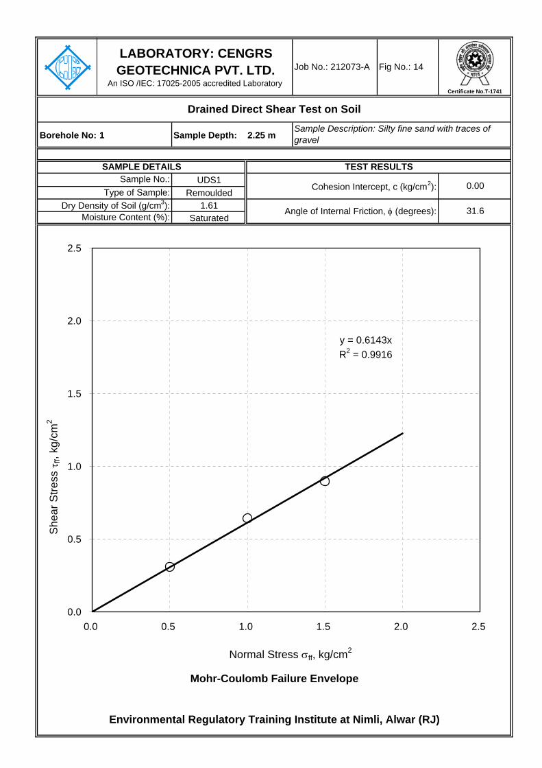
Borehole No: 1 Sample Depth: 2.25 m
UDS1Remoulded
1.61Saturated
Environmental Regulatory Training Institute at Nimli, Alwar (RJ)
Sample No.:Cohesion Intercept, c (kg/cm2): 0.00
Fig No.: 14
Drained Direct Shear Test on Soil
LABORATORY: CENGRS GEOTECHNICA PVT. LTD.
An ISO /IEC: 17025-2005 accredited Laboratory
Job No.: 212073-A
Sample Description: Silty fine sand with traces of gravel
SAMPLE DETAILS TEST RESULTS
Type of Sample:
Mohr-Coulomb Failure Envelope
Dry Density of Soil (g/cm3): Angle of Internal Friction, φ (degrees): 31.6Moisture Content (%):
y = 0.6143xR2 = 0.9916
0.0
0.5
1.0
1.5
2.0
2.5
0.0 0.5 1.0 1.5 2.0 2.5
Normal Stress σff, kg/cm2
She
ar S
tress
τff,
kg/c
m2
Certificate No.T-1741

Borehole No: 1 Sample Depth: 8.25 m
UDS3Remoulded
1.60Saturated
Environmental Regulatory Training Institute at Nimli, Alwar (RJ)
Sample No.:Cohesion Intercept, c (kg/cm2): 0.00
Fig No.: 15
Drained Direct Shear Test on Soil
LABORATORY: CENGRS GEOTECHNICA PVT. LTD.
An ISO /IEC: 17025-2005 accredited Laboratory
Job No.: 212073-A
Sample Description: Silty fine sand
SAMPLE DETAILS TEST RESULTS
Type of Sample:
Mohr-Coulomb Failure Envelope
Dry Density of Soil (g/cm3): Angle of Internal Friction, φ (degrees): 34.3Moisture Content (%):
y = 0.6813xR2 = 0.9942
0.0
0.5
1.0
1.5
2.0
2.5
0.0 0.5 1.0 1.5 2.0 2.5
Normal Stress σff, kg/cm2
She
ar S
tress
τff,
kg/c
m2
Certificate No.T-1741
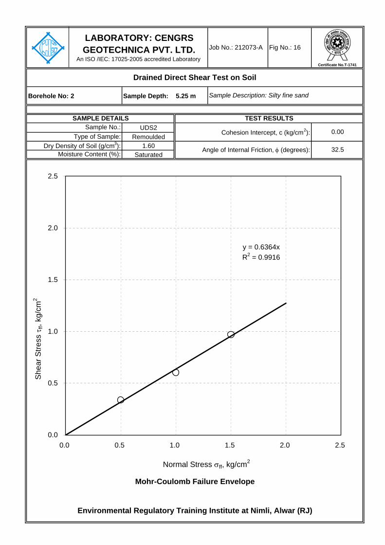
Borehole No: 2 Sample Depth: 5.25 m
UDS2Remoulded
1.60Saturated
Environmental Regulatory Training Institute at Nimli, Alwar (RJ)
Sample No.:Cohesion Intercept, c (kg/cm2): 0.00
Fig No.: 16
Drained Direct Shear Test on Soil
LABORATORY: CENGRS GEOTECHNICA PVT. LTD.
An ISO /IEC: 17025-2005 accredited Laboratory
Job No.: 212073-A
Sample Description: Silty fine sand
SAMPLE DETAILS TEST RESULTS
Type of Sample:
Mohr-Coulomb Failure Envelope
Dry Density of Soil (g/cm3): Angle of Internal Friction, φ (degrees): 32.5Moisture Content (%):
y = 0.6364xR2 = 0.9916
0.0
0.5
1.0
1.5
2.0
2.5
0.0 0.5 1.0 1.5 2.0 2.5
Normal Stress σff, kg/cm2
She
ar S
tress
τff,
kg/c
m2
Certificate No.T-1741

Borehole No: 2 Sample Depth: 11.25 m
UDS4Remoulded
1.52Saturated
Environmental Regulatory Training Institute at Nimli, Alwar (RJ)
Sample No.:Cohesion Intercept, c (kg/cm2): 0.00
Fig No.: 17
Drained Direct Shear Test on Soil
LABORATORY: CENGRS GEOTECHNICA PVT. LTD.
An ISO /IEC: 17025-2005 accredited Laboratory
Job No.: 212073-A
Sample Description: Sandy silt with traces of gravel
SAMPLE DETAILS TEST RESULTS
Type of Sample:
Mohr-Coulomb Failure Envelope
Dry Density of Soil (g/cm3): Angle of Internal Friction, φ (degrees): 31.7Moisture Content (%):
y = 0.618xR2 = 0.9899
0.0
0.5
1.0
1.5
2.0
2.5
0.0 0.5 1.0 1.5 2.0 2.5
Normal Stress σff, kg/cm2
She
ar S
tress
τff,
kg/c
m2
Certificate No.T-1741

Borehole No: 3 Sample Depth: 2.25 m
UDS1Remoulded
1.61Saturated
Environmental Regulatory Training Institute at Nimli, Alwar (RJ)
Sample No.:Cohesion Intercept, c (kg/cm2): 0.00
Fig No.: 18
Drained Direct Shear Test on Soil
LABORATORY: CENGRS GEOTECHNICA PVT. LTD.
An ISO /IEC: 17025-2005 accredited Laboratory
Job No.: 212073-A
Sample Description: Silty fine sand with gravel
SAMPLE DETAILS TEST RESULTS
Type of Sample:
Mohr-Coulomb Failure Envelope
Dry Density of Soil (g/cm3): Angle of Internal Friction, φ (degrees): 34.5Moisture Content (%):
y = 0.6867xR2 = 0.9983
0.0
0.5
1.0
1.5
2.0
2.5
0.0 0.5 1.0 1.5 2.0 2.5
Normal Stress σff, kg/cm2
She
ar S
tress
τff,
kg/c
m2
Certificate No.T-1741
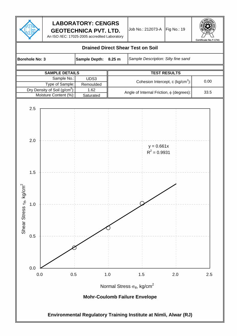
Borehole No: 3 Sample Depth: 8.25 m
UDS3Remoulded
1.62Saturated
Environmental Regulatory Training Institute at Nimli, Alwar (RJ)
Sample No.:Cohesion Intercept, c (kg/cm2): 0.00
Fig No.: 19
Drained Direct Shear Test on Soil
LABORATORY: CENGRS GEOTECHNICA PVT. LTD.
An ISO /IEC: 17025-2005 accredited Laboratory
Job No.: 212073-A
Sample Description: Silty fine sand
SAMPLE DETAILS TEST RESULTS
Type of Sample:
Mohr-Coulomb Failure Envelope
Dry Density of Soil (g/cm3): Angle of Internal Friction, φ (degrees): 33.5Moisture Content (%):
y = 0.661xR2 = 0.9931
0.0
0.5
1.0
1.5
2.0
2.5
0.0 0.5 1.0 1.5 2.0 2.5
Normal Stress σff, kg/cm2
She
ar S
tress
τff,
kg/c
m2
Certificate No.T-1741
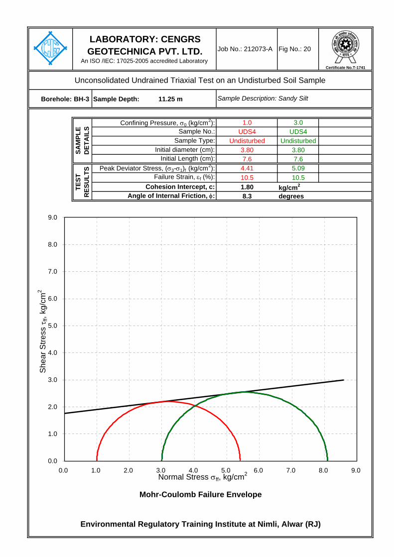
Borehole: BH-3 Sample Depth: 11.25 m
1.0 3.0UDS4 UDS4
Undisturbed Undisturbed3.80 3.807.6 7.64.41 5.0910.5 10.51.80 kg/cm2
8.3 degrees
Environmental Regulatory Training Institute at Nimli, Alwar (RJ)
Mohr-Coulomb Failure Envelope
Failure Strain, εf (%): Cohesion Intercept, c:
Sample Type:
Angle of Internal Friction, φ:
TEST
R
ESU
LTS Peak Deviator Stress, (σ3-σ1)f (kg/cm2):
LABORATORY: CENGRS GEOTECHNICA PVT. LTD.
An ISO /IEC: 17025-2005 accredited Laboratory
Job No.: 212073-A Fig No.: 20
Confining Pressure, σ0 (kg/cm2):
Unconsolidated Undrained Triaxial Test on an Undisturbed Soil Sample
Sample Description: Sandy Silt
SAM
PLE
DET
AIL
S
Initial Length (cm):
Sample No.:
Initial diameter (cm):
0.0
1.0
2.0
3.0
4.0
5.0
6.0
7.0
8.0
9.0
0.0 1.0 2.0 3.0 4.0 5.0 6.0 7.0 8.0 9.0Normal Stress σff, kg/cm2
She
ar S
tress
τff,
kg/c
m2
Certificate No.T-1741

Borehole: BH-5 Sample Depth: 5.25 m
1.0 3.0UDS2 UDS2
Undisturbed Undisturbed3.80 3.807.6 7.62.98 3.746.6 9.21.10 kg/cm2
9.1 degrees
Environmental Regulatory Training Institute at Nimli, Alwar (RJ)
Mohr-Coulomb Failure Envelope
Failure Strain, εf (%): Cohesion Intercept, c:
Sample Type:
Angle of Internal Friction, φ:
TEST
R
ESU
LTS Peak Deviator Stress, (σ3-σ1)f (kg/cm2):
LABORATORY: CENGRS GEOTECHNICA PVT. LTD.
An ISO /IEC: 17025-2005 accredited Laboratory
Job No.: 212073-A Fig No.: 21
Confining Pressure, σ0 (kg/cm2):
Unconsolidated Undrained Triaxial Test on an Undisturbed Soil Sample
Sample Description: Sandy silt with traces of gravel
SAM
PLE
DET
AIL
S
Initial Length (cm):
Sample No.:
Initial diameter (cm):
0.0
1.0
2.0
3.0
4.0
5.0
6.0
7.0
8.0
0.0 1.0 2.0 3.0 4.0 5.0 6.0 7.0 8.0Normal Stress σff, kg/cm2
She
ar S
tress
τff,
kg/c
m2
Certificate No.T-1741

Borehole: BH-5 Sample Depth: 11.25 m
1.0 3.0UDS4 UDS4
Undisturbed Undisturbed3.80 3.807.6 7.63.06 3.9717.1 10.51.10 kg/cm2
10.5 degrees
Environmental Regulatory Training Institute at Nimli, Alwar (RJ)
Mohr-Coulomb Failure Envelope
Failure Strain, εf (%): Cohesion Intercept, c:
Sample Type:
Angle of Internal Friction, φ:
TEST
R
ESU
LTS Peak Deviator Stress, (σ3-σ1)f (kg/cm2):
LABORATORY: CENGRS GEOTECHNICA PVT. LTD.
An ISO /IEC: 17025-2005 accredited Laboratory
Job No.: 212073-A Fig No.: 22
Confining Pressure, σ0 (kg/cm2):
Unconsolidated Undrained Triaxial Test on an Undisturbed Soil Sample
Sample Description: Clayey silt with traces of gravel
SAM
PLE
DET
AIL
S
Initial Length (cm):
Sample No.:
Initial diameter (cm):
0.0
1.0
2.0
3.0
4.0
5.0
6.0
7.0
8.0
0.0 1.0 2.0 3.0 4.0 5.0 6.0 7.0 8.0Normal Stress σff, kg/cm2
She
ar S
tress
τff,
kg/c
m2
Certificate No.T-1741
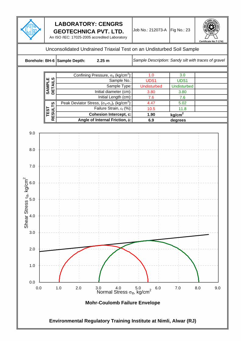
Borehole: BH-6 Sample Depth: 2.25 m
1.0 3.0UDS1 UDS1
Undisturbed Undisturbed3.80 3.807.6 7.64.47 5.0210.5 11.81.90 kg/cm2
6.9 degrees
Environmental Regulatory Training Institute at Nimli, Alwar (RJ)
Mohr-Coulomb Failure Envelope
Failure Strain, εf (%): Cohesion Intercept, c:
Sample Type:
Angle of Internal Friction, φ:
TEST
R
ESU
LTS Peak Deviator Stress, (σ3-σ1)f (kg/cm2):
LABORATORY: CENGRS GEOTECHNICA PVT. LTD.
An ISO /IEC: 17025-2005 accredited Laboratory
Job No.: 212073-A Fig No.: 23
Confining Pressure, σ0 (kg/cm2):
Unconsolidated Undrained Triaxial Test on an Undisturbed Soil Sample
Sample Description: Sandy silt with traces of gravel
SAM
PLE
DET
AIL
S
Initial Length (cm):
Sample No.:
Initial diameter (cm):
0.0
1.0
2.0
3.0
4.0
5.0
6.0
7.0
8.0
9.0
0.0 1.0 2.0 3.0 4.0 5.0 6.0 7.0 8.0 9.0Normal Stress σff, kg/cm2
She
ar S
tress
τff,
kg/c
m2
Certificate No.T-1741
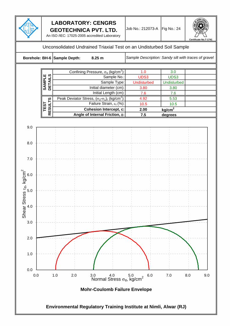
Borehole: BH-6 Sample Depth: 8.25 m
1.0 3.0UDS3 UDS3
Undisturbed Undisturbed3.80 3.807.6 7.64.92 5.5310.5 10.52.00 kg/cm2
7.5 degrees
Environmental Regulatory Training Institute at Nimli, Alwar (RJ)
Mohr-Coulomb Failure Envelope
Failure Strain, εf (%): Cohesion Intercept, c:
Sample Type:
Angle of Internal Friction, φ:
TEST
R
ESU
LTS Peak Deviator Stress, (σ3-σ1)f (kg/cm2):
LABORATORY: CENGRS GEOTECHNICA PVT. LTD.
An ISO /IEC: 17025-2005 accredited Laboratory
Job No.: 212073-A Fig No.: 24
Confining Pressure, σ0 (kg/cm2):
Unconsolidated Undrained Triaxial Test on an Undisturbed Soil Sample
Sample Description: Sandy silt with traces of gravel
SAM
PLE
DET
AIL
S
Initial Length (cm):
Sample No.:
Initial diameter (cm):
0.0
1.0
2.0
3.0
4.0
5.0
6.0
7.0
8.0
9.0
0.0 1.0 2.0 3.0 4.0 5.0 6.0 7.0 8.0 9.0Normal Stress σff, kg/cm2
She
ar S
tress
τff,
kg/c
m2
Certificate No.T-1741

Borehole No: 7 Sample Depth: 5.25 m
UDS2Remoulded
1.60Saturated
Environmental Regulatory Training Institute at Nimli, Alwar (RJ)
Sample No.:Cohesion Intercept, c (kg/cm2): 0.00
Fig No.: 25
Drained Direct Shear Test on Soil
LABORATORY: CENGRS GEOTECHNICA PVT. LTD.
An ISO /IEC: 17025-2005 accredited Laboratory
Job No.: 212073-A
Sample Description: Silty fine sand
SAMPLE DETAILS TEST RESULTS
Type of Sample:
Mohr-Coulomb Failure Envelope
Dry Density of Soil (g/cm3): Angle of Internal Friction, φ (degrees): 32.8Moisture Content (%):
y = 0.6438xR2 = 0.9903
0.0
0.5
1.0
1.5
2.0
2.5
0.0 0.5 1.0 1.5 2.0 2.5
Normal Stress σff, kg/cm2
She
ar S
tress
τff,
kg/c
m2
Certificate No.T-1741

Borehole No: 7 Sample Depth: 11.25 m
UDS4Remoulded
1.62Saturated
Environmental Regulatory Training Institute at Nimli, Alwar (RJ)
Sample No.:Cohesion Intercept, c (kg/cm2): 0.00
Fig No.: 26
Drained Direct Shear Test on Soil
LABORATORY: CENGRS GEOTECHNICA PVT. LTD.
An ISO /IEC: 17025-2005 accredited Laboratory
Job No.: 212073-A
Sample Description: Silty fine sand with traces of gravel
SAMPLE DETAILS TEST RESULTS
Type of Sample:
Mohr-Coulomb Failure Envelope
Dry Density of Soil (g/cm3): Angle of Internal Friction, φ (degrees): 36.6Moisture Content (%):
y = 0.7437xR2 = 0.9959
0.0
0.5
1.0
1.5
2.0
2.5
0.0 0.5 1.0 1.5 2.0 2.5
Normal Stress σff, kg/cm2
She
ar S
tress
τff,
kg/c
m2
Certificate No.T-1741

Borehole No: 8 Sample Depth: 2.25 m
UDS1Remoulded
1.57Saturated
Environmental Regulatory Training Institute at Nimli, Alwar (RJ)
Sample No.:Cohesion Intercept, c (kg/cm2): 0.00
Fig No.: 27
Drained Direct Shear Test on Soil
LABORATORY: CENGRS GEOTECHNICA PVT. LTD.
An ISO /IEC: 17025-2005 accredited Laboratory
Job No.: 212073-A
Sample Description: Silty fine sand
SAMPLE DETAILS TEST RESULTS
Type of Sample:
Mohr-Coulomb Failure Envelope
Dry Density of Soil (g/cm3): Angle of Internal Friction, φ (degrees): 33.9Moisture Content (%):
y = 0.6716xR2 = 0.9955
0.0
0.5
1.0
1.5
2.0
2.5
0.0 0.5 1.0 1.5 2.0 2.5
Normal Stress σff, kg/cm2
She
ar S
tress
τff,
kg/c
m2
Certificate No.T-1741

Borehole No: 8 Sample Depth: 8.25 m
UDS3Remoulded
1.60Saturated
Environmental Regulatory Training Institute at Nimli, Alwar (RJ)
Sample No.:Cohesion Intercept, c (kg/cm2): 0.00
Fig No.: 28
Drained Direct Shear Test on Soil
LABORATORY: CENGRS GEOTECHNICA PVT. LTD.
An ISO /IEC: 17025-2005 accredited Laboratory
Job No.: 212073-A
Sample Description: Sandy silt with traces of gravel
SAMPLE DETAILS TEST RESULTS
Type of Sample:
Mohr-Coulomb Failure Envelope
Dry Density of Soil (g/cm3): Angle of Internal Friction, φ (degrees): 33.1Moisture Content (%):
y = 0.651xR2 = 0.9936
0.0
0.5
1.0
1.5
2.0
2.5
0.0 0.5 1.0 1.5 2.0 2.5
Normal Stress σff, kg/cm2
She
ar S
tress
τff,
kg/c
m2
Certificate No.T-1741

Borehole No: 9 Sample Depth: 5.25 m
UDS2Remoulded
1.61Saturated
Environmental Regulatory Training Institute at Nimli, Alwar (RJ)
Sample No.:Cohesion Intercept, c (kg/cm2): 0.00
Fig No.: 29
Drained Direct Shear Test on Soil
LABORATORY: CENGRS GEOTECHNICA PVT. LTD.
An ISO /IEC: 17025-2005 accredited Laboratory
Job No.: 212073-A
Sample Description: Silty fine sand
SAMPLE DETAILS TEST RESULTS
Type of Sample:
Mohr-Coulomb Failure Envelope
Dry Density of Soil (g/cm3): Angle of Internal Friction, φ (degrees): 34.5Moisture Content (%):
y = 0.6881xR2 = 0.9968
0.0
0.5
1.0
1.5
2.0
2.5
0.0 0.5 1.0 1.5 2.0 2.5
Normal Stress σff, kg/cm2
She
ar S
tress
τff,
kg/c
m2
Certificate No.T-1741

Borehole: BH-9 Sample Depth: 11.25 m
1.0 3.0UDS4 UDS4
Undisturbed Undisturbed3.80 3.807.6 7.64.55 5.159.2 10.51.90 kg/cm2
7.4 degrees
Environmental Regulatory Training Institute at Nimli, Alwar (RJ)
Mohr-Coulomb Failure Envelope
Failure Strain, εf (%): Cohesion Intercept, c:
Sample Type:
Angle of Internal Friction, φ:
TEST
R
ESU
LTS Peak Deviator Stress, (σ3-σ1)f (kg/cm2):
LABORATORY: CENGRS GEOTECHNICA PVT. LTD.
An ISO /IEC: 17025-2005 accredited Laboratory
Job No.: 212073-A Fig No.: 30
Confining Pressure, σ0 (kg/cm2):
Unconsolidated Undrained Triaxial Test on an Undisturbed Soil Sample
Sample Description: Sandy silt with traces of gravel
SAM
PLE
DET
AIL
S
Initial Length (cm):
Sample No.:
Initial diameter (cm):
0.0
1.0
2.0
3.0
4.0
5.0
6.0
7.0
8.0
9.0
0.0 1.0 2.0 3.0 4.0 5.0 6.0 7.0 8.0 9.0Normal Stress σff, kg/cm2
She
ar S
tress
τff,
kg/c
m2
Certificate No.T-1741

Borehole No: 10 Sample Depth: 8.25 m
UDS3Remoulded
1.61Saturated
Environmental Regulatory Training Institute at Nimli, Alwar (RJ)
Sample No.:Cohesion Intercept, c (kg/cm2): 0.00
Fig No.: 31
Drained Direct Shear Test on Soil
LABORATORY: CENGRS GEOTECHNICA PVT. LTD.
An ISO /IEC: 17025-2005 accredited Laboratory
Job No.: 212073-A
Sample Description: Silty fine sand with traces of gravel
SAMPLE DETAILS TEST RESULTS
Type of Sample:
Mohr-Coulomb Failure Envelope
Dry Density of Soil (g/cm3): Angle of Internal Friction, φ (degrees): 34.2Moisture Content (%):
y = 0.6794xR2 = 0.9994
0.0
0.5
1.0
1.5
2.0
2.5
0.0 0.5 1.0 1.5 2.0 2.5
Normal Stress σff, kg/cm2
She
ar S
tress
τff,
kg/c
m2
Certificate No.T-1741

TYPICAL CALCULATIONS

Job No. 212073-A Sheet No. 1
c =B =
FS =
c = 0.00 T/m2 φ = 30.0c' = 0.00 T/m2 φ'= 21.1 γ
Nc = Nq = Nγ = From To T/m3
Nc' = Nq
' = Nγ' = 0.0 3.0 1.70
3.0 6.0 1.802.5 6.0 9.0 1.90
9.0 12.0 2.00
V 0.60
Y
1.5
B, m L, m ζc ζq ζγ dc dq dγ dc' dq' dγ
' GSF LSF
2.0 2.0 Square 1.5 0.60 1.30 1.20 0.80 1.00 1.00 1.00 28.7 3.0 3.0 Square 1.5 0.60 1.30 1.20 0.80 1.00 1.00 1.00 32.6 2.0 2.0 Square 2.5 0.60 1.30 1.20 0.80 1.17 1.09 1.09 46.9 3.0 3.0 Square 2.5 0.60 1.30 1.20 0.80 1.12 1.06 1.06 49.7
qnet safe =
Depth factors Shape factors
q =γ =
ζc, ζq, ζγ =
cohesion interceptFoundation width
Bulk density of soil below founding level
safe net bearing capacity
m SHEAR FAILURE
General Shear Failure :
FAILURE CRITERIA :
For computation of Depth Factor, depth below GL to be ignored to account for loose soils,poorly compacted backfill above foundation, scour etc. =
NOT MET
IS 1904-1986
Design Water Table depth =
Soil parameters :
Rw =
dc, dq, dγ = bearing capacity factors, which are a function of φNc, Nq, Nγ =Water table correction factor
CENGRS GEOTECHNICA PVT. LTDNEW DELHI
Rw =
Analysis as per IS 6403-1981
Factor of safety
degreesdegrees
Bulk Density Profile
Safe Net Bearing Capacity
T/m2
BEARING CAPACITY ANALYSIS FOR SHALLOW FOUNDATIONS
qnet safe = (1/FS){cNcζcdc+q(Nq-1)ζqdq+0.5BγNγζγdγRw}
Depth factor to be considered ?
Depth, m
Factor of safety =
qnet safe , T/m2
Rw factor: Constant value(V) for worst condition or calculate(C) based on WT Depth ? :
Project :
overburden pressure
Foundation Dimensions
28.7
Rw
49.7
FOUN-DATION SHAPE
32.6
46.9
Depth factors (LSF)Shape Factors
Environmental Regulatory Training Institute at Nimli, Alwar, (Raj)BH-1, BH-6 & BH-10
The bearing capacity equation is as follows :
where:
Dep
th,m Depth factors
(GSF)
GENERAL
30.14
as per
15.87 7.1118.40
Local Shear Failure :
22.406.24
GENERAL SHEAR FAILURELOCAL SHEAR FAILURE
Gross Bearing Capacity
(Safe) T/m2
31.335.151.1
54.0
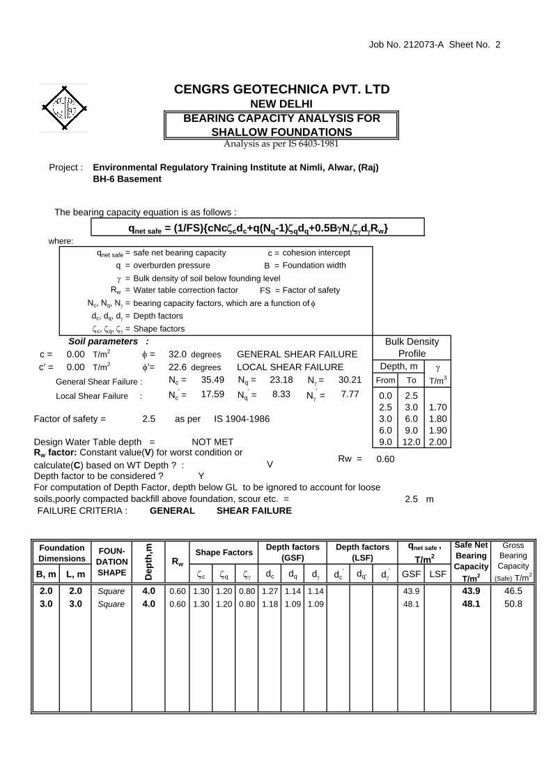
Job No. 212073-A Sheet No. 2
c =B =
FS =
c = 0.00 T/m2 φ = 32.0c' = 0.00 T/m2 φ'= 22.6 γ
Nc = Nq = Nγ = From To T/m3
Nc' = Nq
' = Nγ' = 0.0 2.5
2.5 3.0 1.702.5 3.0 6.0 1.80
6.0 9.0 1.909.0 12.0 2.00
V 0.60
Y
2.5
B, m L, m ζc ζq ζγ dc dq dγ dc' dq' dγ
' GSF LSF
2.0 2.0 Square 4.0 0.60 1.30 1.20 0.80 1.27 1.14 1.14 43.9 3.0 3.0 Square 4.0 0.60 1.30 1.20 0.80 1.18 1.09 1.09 48.1
qnet safe =
Depth factors Shape factors
q =γ =
ζc, ζq, ζγ =
cohesion interceptFoundation width
Bulk density of soil below founding level
safe net bearing capacity
m SHEAR FAILURE
General Shear Failure :
FAILURE CRITERIA :
For computation of Depth Factor, depth below GL to be ignored to account for loose soils,poorly compacted backfill above foundation, scour etc. =
NOT MET
IS 1904-1986
Design Water Table depth =
Soil parameters :
Rw =
dc, dq, dγ = bearing capacity factors, which are a function of φNc, Nq, Nγ =Water table correction factor
CENGRS GEOTECHNICA PVT. LTDNEW DELHI
Rw =
Analysis as per IS 6403-1981
Factor of safety
degreesdegrees
Bulk Density Profile
Safe Net Bearing Capacity
T/m2
BEARING CAPACITY ANALYSIS FOR SHALLOW FOUNDATIONS
qnet safe = (1/FS){cNcζcdc+q(Nq-1)ζqdq+0.5BγNγζγdγRw}
Depth factor to be considered ?
Depth, m
Factor of safety =
qnet safe , T/m2
Rw factor: Constant value(V) for worst condition or calculate(C) based on WT Depth ? :
Project :
overburden pressure
Foundation Dimensions
43.9
Rw
FOUN-DATION SHAPE
48.1
Depth factors (LSF)Shape Factors
Environmental Regulatory Training Institute at Nimli, Alwar, (Raj)BH-6 Basement
The bearing capacity equation is as follows :
where:
Dep
th,m Depth factors
(GSF)
GENERAL
35.49
as per
17.59 8.3323.18
Local Shear Failure :
30.217.77
GENERAL SHEAR FAILURELOCAL SHEAR FAILURE
Gross Bearing Capacity
(Safe) T/m2
46.550.8
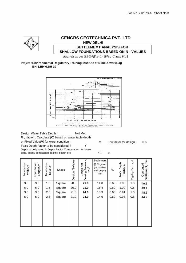
Job No. 212073-A Sheet No.3
Project :
V 0.6Y
1.5
Foun
datio
n W
idth
,m
Foun
datio
n Le
ngth
,m
Foun
datio
n D
epth
,m
Shape
Des
ign
N-V
alue
Des
ign
Net
Be
arin
g Pr
essu
re,
T/m
2
Settlement @ 1kg/cm2
(as read off from graph),
mmRw
Fox'
s D
epth
Fa
ctor
, df
Rig
idity
Fac
tor,
d r
Com
pute
d S
ettle
men
t, m
m
3.0 3.0 1.5 Square 20.0 21.0 14.0 0.60 1.00 1.0 49.16.0 6.0 1.5 Square 20.0 21.0 15.4 0.60 1.00 0.8 43.13.0 3.0 2.5 Square 21.0 24.0 13.3 0.60 0.91 1.0 48.36.0 6.0 2.5 Square 21.0 24.0 14.6 0.60 0.96 0.8 44.7
mDepth to be ignored in Depth Factor Computation for loose soils, poorly compacted backfill, scour, etc.
R w factor : Calculate (C) based on water table depth or Fixed Value(V) for worst condition :
Not Met
Rw factor for design :
Design Water Table Depth :
Fox's Depth Factor to be considered ?
CENGRS GEOTECHNICA PVT. LTDNEW DELHI
SETTLEMEMT ANALYSIS FOR SHALLOW FOUNDATIONS BASED ON N - VALUES
Environmental Regulatory Training Institute at Nimli.Alwar.(Raj)
Analysis as per IS:8009(Part 1)-1976 , Clause 9.1.4
BH-1,BH-6,BH 10

Job No. 212073-A Sheet No.4
Project :
V 0.6Y
2.5
Foun
datio
n W
idth
,m
Foun
datio
n Le
ngth
,m
Foun
datio
n D
epth
,m
Shape
Des
ign
N-V
alue
Des
ign
Net
Be
arin
g Pr
essu
re,
T/m
2
Settlement @ 1kg/cm2
(as read off from graph),
mmRw
Fox'
s D
epth
Fa
ctor
, df
Rig
idity
Fac
tor,
d r
Com
pute
d S
ettle
men
t, m
m
3.0 3.0 4.0 Square 25.0 30.0 10.8 0.60 0.85 1.0 46.16.0 6.0 4.0 Square 25.0 30.0 11.9 0.60 0.94 0.8 44.8
Environmental Regulatory Training Institute at Nimli.Alwar.(Raj)
Analysis as per IS:8009(Part 1)-1976 , Clause 9.1.4
BH-6 Basement
CENGRS GEOTECHNICA PVT. LTDNEW DELHI
SETTLEMEMT ANALYSIS FOR SHALLOW FOUNDATIONS BASED ON N - VALUES
mDepth to be ignored in Depth Factor Computation for loose soils, poorly compacted backfill, scour, etc.
R w factor : Calculate (C) based on water table depth or Fixed Value(V) for worst condition :
Not Met
Rw factor for design :
Design Water Table Depth :
Fox's Depth Factor to be considered ?

Job No. 212073-A Sheet No. 5
c =B =
FS =
c = 0.00 T/m2 φ = 33.0c' = 0.00 T/m2 φ'= 23.4 γ
Nc = Nq = Nγ = From To T/m3
Nc' = Nq
' = Nγ' = 0.0 2.0
2.0 6.0 1.752.5 6.0 9.0 1.85
9.0 12.0 1.90
V 0.60
Y
2.0
B, m L, m ζc ζq ζγ dc dq dγ dc' dq' dγ
' GSF LSF
3.0 3.0 Square 3.0 0.60 1.30 1.20 0.80 1.12 1.06 1.06 41.2 6.0 6.0 Square 3.0 0.60 1.30 1.20 0.80 1.06 1.03 1.03 59.3
Gross Bearing Capacity
(Safe) T/m2
42.961.1
35.198.69
GENERAL SHEAR FAILURELOCAL SHEAR FAILURE
Dep
th,m Depth factors
(GSF)
GENERAL
38.64
as per
18.56 9.0326.09
Local Shear Failure :
Environmental Regulatory Training Institute at Nimli, Alwar, (Raj)BH-4 Basement
The bearing capacity equation is as follows :
where:
Depth factors (LSF)Shape Factors
Foundation Dimensions
41.2
Rw
FOUN-DATION SHAPE
59.3
Safe Net Bearing Capacity
T/m2
BEARING CAPACITY ANALYSIS FOR SHALLOW FOUNDATIONS
qnet safe = (1/FS){cNcζcdc+q(Nq-1)ζqdq+0.5BγNγζγdγRw}
Depth factor to be considered ?
Depth, m
Factor of safety =
qnet safe , T/m2
Rw factor: Constant value(V) for worst condition or calculate(C) based on WT Depth ? :
Project :
overburden pressure
CENGRS GEOTECHNICA PVT. LTDNEW DELHI
Rw =
Analysis as per IS 6403-1981
Factor of safety
degreesdegrees
Bulk Density Profile
Soil parameters :
Rw =
dc, dq, dγ = bearing capacity factors, which are a function of φNc, Nq, Nγ =Water table correction factor
m SHEAR FAILURE
General Shear Failure :
FAILURE CRITERIA :
For computation of Depth Factor, depth below GL to be ignored to account for loose soils,poorly compacted backfill above foundation, scour etc. =
NOT MET
IS 1904-1986
Design Water Table depth =
qnet safe =
Depth factors Shape factors
q =γ =
ζc, ζq, ζγ =
cohesion interceptFoundation width
Bulk density of soil below founding level
safe net bearing capacity

Job No. 212073-A Sheet No. 6
Project :
V 0.6Y
2.0
Foun
datio
n W
idth
,m
Foun
datio
n Le
ngth
,m
Foun
datio
n D
epth
,m
Shape
Des
ign
N-V
alue
Des
ign
Net
Be
arin
g Pr
essu
re,
T/m
2
Settlement @ 1kg/cm2
(as read off from graph),
mmRw
Fox'
s D
epth
Fa
ctor
, df
Rig
idity
Fac
tor,
d r
Com
pute
d S
ettle
men
t, m
m
3.0 3.0 3.0 Square 50.0 30.0 5.1 0.60 0.91 1.0 23.16.0 6.0 3.0 Square 50.0 30.0 5.6 0.60 0.96 0.8 21.4
mDepth to be ignored in Depth Factor Computation for loose soils, poorly compacted backfill, scour, etc.
R w factor : Calculate (C) based on water table depth or Fixed Value(V) for worst condition :
Not Met
Rw factor for design :
Design Water Table Depth :
Fox's Depth Factor to be considered ?
CENGRS GEOTECHNICA PVT. LTDNEW DELHI
SETTLEMEMT ANALYSIS FOR SHALLOW FOUNDATIONS BASED ON N - VALUES
Environmental Regulatory Training Institute at Nimli.Alwar.(Raj)
Analysis as per IS:8009(Part 1)-1976 , Clause 9.1.4
BH-4 Basement
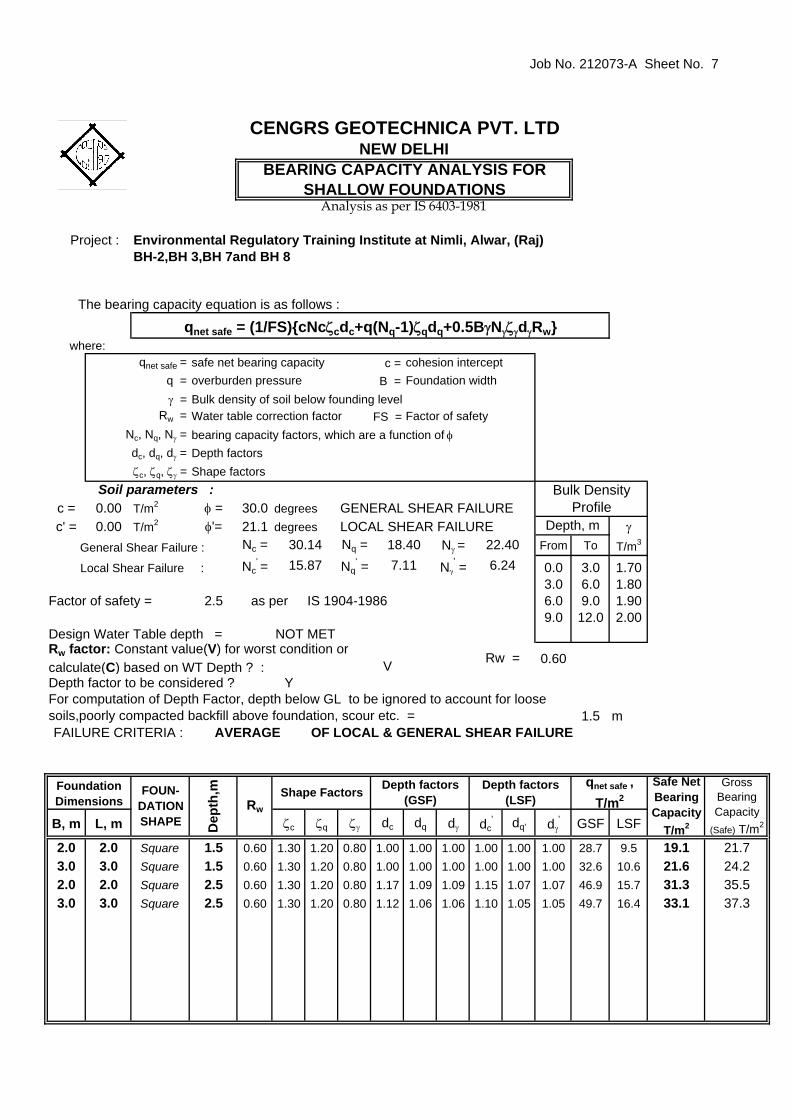
Job No. 212073-A Sheet No. 7
c =B =
FS =
c = 0.00 T/m2 φ = 30.0c' = 0.00 T/m2 φ'= 21.1 γ
Nc = Nq = Nγ = From To T/m3
Nc' = Nq
' = Nγ' = 0.0 3.0 1.70
3.0 6.0 1.802.5 6.0 9.0 1.90
9.0 12.0 2.00
V 0.60
Y
1.5
B, m L, m ζc ζq ζγ dc dq dγ dc' dq' dγ
' GSF LSF
2.0 2.0 Square 1.5 0.60 1.30 1.20 0.80 1.00 1.00 1.00 1.00 1.00 1.00 28.7 9.53.0 3.0 Square 1.5 0.60 1.30 1.20 0.80 1.00 1.00 1.00 1.00 1.00 1.00 32.6 10.62.0 2.0 Square 2.5 0.60 1.30 1.20 0.80 1.17 1.09 1.09 1.15 1.07 1.07 46.9 15.73.0 3.0 Square 2.5 0.60 1.30 1.20 0.80 1.12 1.06 1.06 1.10 1.05 1.05 49.7 16.4
37.3
Gross Bearing Capacity
(Safe) T/m2
21.724.235.5
22.406.24
GENERAL SHEAR FAILURELOCAL SHEAR FAILURE
Dep
th,m Depth factors
(GSF)
AVERAGE
30.14
as per
15.87 7.1118.40
Local Shear Failure :
Environmental Regulatory Training Institute at Nimli, Alwar, (Raj)BH-2,BH 3,BH 7and BH 8
The bearing capacity equation is as follows :
where:
31.3
Depth factors (LSF)Shape Factors
Foundation Dimensions
19.1
Rw
33.1
FOUN-DATION SHAPE
21.6
Safe Net Bearing Capacity
T/m2
BEARING CAPACITY ANALYSIS FOR SHALLOW FOUNDATIONS
qnet safe = (1/FS){cNcζcdc+q(Nq-1)ζqdq+0.5BγNγζγdγRw}
Depth factor to be considered ?
Depth, m
Factor of safety =
qnet safe , T/m2
Rw factor: Constant value(V) for worst condition or calculate(C) based on WT Depth ? :
Project :
overburden pressure
CENGRS GEOTECHNICA PVT. LTDNEW DELHI
Rw =
Analysis as per IS 6403-1981
Factor of safety
degreesdegrees
Bulk Density Profile
Soil parameters :
Rw =
dc, dq, dγ = bearing capacity factors, which are a function of φNc, Nq, Nγ =Water table correction factor
m OF LOCAL & GENERAL SHEAR FAILURE
General Shear Failure :
FAILURE CRITERIA :
For computation of Depth Factor, depth below GL to be ignored to account for loose soils,poorly compacted backfill above foundation, scour etc. =
NOT MET
IS 1904-1986
Design Water Table depth =
qnet safe =
Depth factors Shape factors
q =γ =
ζc, ζq, ζγ =
cohesion interceptFoundation width
Bulk density of soil below founding level
safe net bearing capacity

Job No. 212073-A Sheet No.8
Project :
V 0.6Y
1.5
Foun
datio
n W
idth
,m
Foun
datio
n Le
ngth
,m
Foun
datio
n D
epth
,m
Shape
Des
ign
N-V
alue
Des
ign
Net
Be
arin
g Pr
essu
re,
T/m
2
Settlement @ 1kg/cm2
(as read off from graph),
mmRw
Fox'
s D
epth
Fa
ctor
, df
Rig
idity
Fac
tor,
d r
Com
pute
d S
ettle
men
t, m
m
3.0 3.0 1.5 Square 14.0 13.5 21.7 0.60 1.00 1.0 48.86.0 6.0 1.5 Square 14.0 13.5 23.8 0.60 1.00 0.8 42.93.0 3.0 2.5 Square 15.0 16.5 19.9 0.60 0.91 1.0 49.86.0 6.0 2.5 Square 15.0 16.5 21.8 0.60 0.96 0.8 46.1
mDepth to be ignored in Depth Factor Computation for loose soils, poorly compacted backfill, scour, etc.
R w factor : Calculate (C) based on water table depth or Fixed Value(V) for worst condition :
Not Met
Rw factor for design :
Design Water Table Depth :
Fox's Depth Factor to be considered ?
CENGRS GEOTECHNICA PVT. LTDNEW DELHI
SETTLEMEMT ANALYSIS FOR SHALLOW FOUNDATIONS BASED ON N - VALUES
Environmental Regulatory Training Institute at Nimli.Alwar.(Raj)
Analysis as per IS:8009(Part 1)-1976 , Clause 9.1.4
BH-2,BH-3,BH-7 and BH-8

Job No. 212073-A Sheet No. 9
c =B =
FS =
c = 0.00 T/m2 φ = 30.0c' = 0.00 T/m2 φ'= 21.1 γ
Nc = Nq = Nγ = From To T/m3
Nc' = Nq
' = Nγ' = 0.0 3.0 1.70
3.0 6.0 1.802.5 6.0 9.0 1.90
9.0 12.0 2.00
V 0.60
Y
1.5
B, m L, m ζc ζq ζγ dc dq dγ dc' dq' dγ
' GSF LSF
3.0 3.0 Square 1.5 0.60 1.30 1.20 0.80 1.00 1.00 1.00 32.6 6.0 6.0 Square 1.5 0.60 1.30 1.20 0.80 1.00 1.00 1.00 44.5 2.0 2.0 Square 2.5 0.60 1.30 1.20 0.80 1.17 1.09 1.09 46.9 3.0 3.0 Square 2.5 0.60 1.30 1.20 0.80 1.12 1.06 1.06 49.7
qnet safe =
Depth factors Shape factors
q =γ =
ζc, ζq, ζγ =
cohesion interceptFoundation width
Bulk density of soil below founding level
safe net bearing capacity
m SHEAR FAILURE
General Shear Failure :
FAILURE CRITERIA :
For computation of Depth Factor, depth below GL to be ignored to account for loose soils,poorly compacted backfill above foundation, scour etc. =
NOT MET
IS 1904-1986
Design Water Table depth =
Soil parameters :
Rw =
dc, dq, dγ = bearing capacity factors, which are a function of φNc, Nq, Nγ =Water table correction factor
CENGRS GEOTECHNICA PVT. LTDNEW DELHI
Rw =
Analysis as per IS 6403-1981
Factor of safety
degreesdegrees
Bulk Density Profile
Safe Net Bearing Capacity
T/m2
BEARING CAPACITY ANALYSIS FOR SHALLOW FOUNDATIONS
qnet safe = (1/FS){cNcζcdc+q(Nq-1)ζqdq+0.5BγNγζγdγRw}
Depth factor to be considered ?
Depth, m
Factor of safety =
qnet safe , T/m2
Rw factor: Constant value(V) for worst condition or calculate(C) based on WT Depth ? :
Project :
overburden pressure
Foundation Dimensions
32.6
Rw
49.7
FOUN-DATION SHAPE
44.5
46.9
Depth factors (LSF)Shape Factors
Environmental Regulatory Training Institute at Nimli, Alwar, (Raj)BH-5and BH 9
The bearing capacity equation is as follows :
where:
Dep
th,m Depth factors
(GSF)
GENERAL
30.14
as per
15.87 7.1118.40
Local Shear Failure :
22.406.24
GENERAL SHEAR FAILURELOCAL SHEAR FAILURE
Gross Bearing Capacity
(Safe) T/m2
35.147.151.1
54.0

Job No. 212073-A Sheet No. 10
c =B =
FS =
c = 0.00 T/m2 φ = 30.0c' = 0.00 T/m2 φ'= 21.1 γ
Nc = Nq = Nγ = From To T/m3
Nc' = Nq
' = Nγ' = 0.0 2.0
2.0 3.0 1.702.5 3.0 6.0 1.80
6.0 9.0 1.909.0 12.0 2.00
V 0.60
Y
2.0
B, m L, m ζc ζq ζγ dc dq dγ dc' dq' dγ
' GSF LSF
3.0 3.0 Square 4.0 0.60 1.30 1.20 0.80 1.23 1.12 1.12 45.8 6.0 6.0 Square 4.0 0.60 1.30 1.20 0.80 1.12 1.06 1.06 56.6
qnet safe =
Depth factors Shape factors
q =γ =
ζc, ζq, ζγ =
cohesion interceptFoundation width
Bulk density of soil below founding level
safe net bearing capacity
m SHEAR FAILURE
General Shear Failure :
FAILURE CRITERIA :
For computation of Depth Factor, depth below GL to be ignored to account for loose soils,poorly compacted backfill above foundation, scour etc. =
NOT MET
IS 1904-1986
Design Water Table depth =
Soil parameters :
Rw =
dc, dq, dγ = bearing capacity factors, which are a function of φNc, Nq, Nγ =Water table correction factor
CENGRS GEOTECHNICA PVT. LTDNEW DELHI
Rw =
Analysis as per IS 6403-1981
Factor of safety
degreesdegrees
Bulk Density Profile
Safe Net Bearing Capacity
T/m2
BEARING CAPACITY ANALYSIS FOR SHALLOW FOUNDATIONS
qnet safe = (1/FS){cNcζcdc+q(Nq-1)ζqdq+0.5BγNγζγdγRw}
Depth factor to be considered ?
Depth, m
Factor of safety =
qnet safe , T/m2
Rw factor: Constant value(V) for worst condition or calculate(C) based on WT Depth ? :
Project :
overburden pressure
Foundation Dimensions
45.8
Rw
FOUN-DATION SHAPE
56.6
Depth factors (LSF)Shape Factors
Environmental Regulatory Training Institute at Nimli, Alwar, (Raj)BH-5 Basement
The bearing capacity equation is as follows :
where:
Dep
th,m Depth factors
(GSF)
GENERAL
30.14
as per
15.87 7.1118.40
Local Shear Failure :
22.406.24
GENERAL SHEAR FAILURELOCAL SHEAR FAILURE
Gross Bearing Capacity
(Safe) T/m2
49.360.1

Job No. 212073-A Sheet No. 11
Project :
V 0.6Y
1.5
Foun
datio
n W
idth
,m
Foun
datio
n Le
ngth
,m
Foun
datio
n D
epth
,m
Shape
Des
ign
N-V
alue
Des
ign
Net
Be
arin
g Pr
essu
re,
T/m
2
Settlement @ 1kg/cm2
(as read off from graph),
mmRw
Fox'
s D
epth
Fa
ctor
, df
Rig
idity
Fac
tor,
d r
Com
pute
d S
ettle
men
t, m
m
3.0 3.0 1.5 Square 20.0 21.0 14.0 0.60 1.00 1.0 49.16.0 6.0 1.5 Square 20.0 21.0 15.4 0.60 1.00 0.8 43.13.0 3.0 2.5 Square 22.0 26.0 12.6 0.60 0.91 1.0 49.56.0 6.0 2.5 Square 22.0 26.0 13.8 0.60 0.96 0.8 45.9
mDepth to be ignored in Depth Factor Computation for loose soils, poorly compacted backfill, scour, etc.
R w factor : Calculate (C) based on water table depth or Fixed Value(V) for worst condition :
Not Met
Rw factor for design :
Design Water Table Depth :
Fox's Depth Factor to be considered ?
CENGRS GEOTECHNICA PVT. LTDNEW DELHI
SETTLEMEMT ANALYSIS FOR SHALLOW FOUNDATIONS BASED ON N - VALUES
Environmental Regulatory Training Institute at Nimli.Alwar.(Raj)
Analysis as per IS:8009(Part 1)-1976 , Clause 9.1.4
BH 5 and BH 9
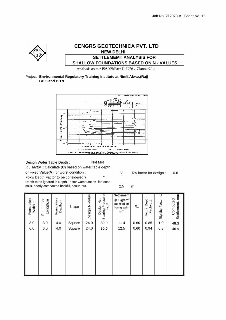
Job No. 212073-A Sheet No. 12
Project :
V 0.6Y
2.5
Foun
datio
n W
idth
,m
Foun
datio
n Le
ngth
,m
Foun
datio
n D
epth
,m
Shape
Des
ign
N-V
alue
Des
ign
Net
Be
arin
g Pr
essu
re,
T/m
2
Settlement @ 1kg/cm2
(as read off from graph),
mmRw
Fox'
s D
epth
Fa
ctor
, df
Rig
idity
Fac
tor,
d r
Com
pute
d S
ettle
men
t, m
m
3.0 3.0 4.0 Square 24.0 30.0 11.4 0.60 0.85 1.0 48.36.0 6.0 4.0 Square 24.0 30.0 12.5 0.60 0.94 0.8 46.9
Environmental Regulatory Training Institute at Nimli.Alwar.(Raj)
Analysis as per IS:8009(Part 1)-1976 , Clause 9.1.4
BH 5 and BH 9
CENGRS GEOTECHNICA PVT. LTDNEW DELHI
SETTLEMEMT ANALYSIS FOR SHALLOW FOUNDATIONS BASED ON N - VALUES
mDepth to be ignored in Depth Factor Computation for loose soils, poorly compacted backfill, scour, etc.
R w factor : Calculate (C) based on water table depth or Fixed Value(V) for worst condition :
Not Met
Rw factor for design :
Design Water Table Depth :
Fox's Depth Factor to be considered ?


![Studia Geotechnica et Mechanica [No. 1-2 (2007)]](https://img.dokumen.tips/doc/110x75/5876004b1a28abd8348b68c0/studia-geotechnica-et-mechanica-no-1-2-2007.jpg)

