Embed Size (px)
Citation preview

Schweizerische Unfalluntersuchungsstelle SUST Service d’enquête suisse sur les accidents SESA Servizio d’inchiesta svizzero sugli infortuni SISI Swiss Accident Investigation Board SAIB Aviation Division
Aéropole 1, Route de Morens, 1530 Payerne Tel. +41 26 662 33 00, Fax +41 26 662 33 01 [email protected] www.saib.admin.ch
Final Report No. 2142
by the Swiss Accident
Investigation Board SAIB concerning the accident involving the K-1200 K-MAX helicopter, registration HB-ZEH on 2 October 2007 in Strit, municipality of Illgau/SZ

Final Report HB-ZEH
Swiss Accident Investigation Board Page 2 of 39
Ursachen
Der Unfall ist auf ein Versagen des Triebwerks auf einer Flughöhe, bei welcher eine erfolg-reiche Autorotation nicht möglich war, zurückzuführen.
Die deutlichen Anzeichen eines Defektes am Triebwerk wurden nicht konsequent angegan-gen.

Final Report HB-ZEH
Swiss Accident Investigation Board Page 3 of 39
General information on this report
This report contains the Swiss Accident Investigation Board’s (SAIB) conclusions on the cir-cumstances and causes of the accident which is the subject of the investigation.
In accordance with Art 3.1 of the 10th edition, applicable from 18th November 2010, of Annex 13 to the Convention on International Civil Aviation of 7 December 1944 and Article 24 of the Federal Air Navigation Act, the sole purpose of the investigation of an aircraft accident or serious incident is to prevent accidents or serious incidents. The legal assessment of acci-dent/incident causes and circumstances is expressly no concern of the accident investiga-tion. It is therefore not the purpose of this investigation to determine blame or clarify ques-tions of liability.
If this report is used for purposes other than accident prevention, due consideration shall be given to this circumstance.
The definitive version of this report is the original in the German language.
All times in this report, unless otherwise indicated, are stated in local time (LT). At the time of the accident, Central European Summer Time (CEST) applied as local time in Switzerland. The relation between LT, CEST and UTC is: LT = CEST = UTC + 2 hours.

Final Report HB-ZEH
Swiss Accident Investigation Board Page 4 of 39
Contents
Synopsis .................................................................................................................... 6
Investigation ............................................................................................................. 6
Synopsis .................................................................................................................... 6
Causes ....................................................................................................................... 6
1 Factual information ............................................................................................ 7
1.1 History of the flight .................................................................................................................... 7 1.1.1 General ................................................................................................................................ 7 1.1.2 Previous events ................................................................................................................... 7 1.1.3 History of the flight ............................................................................................................... 7 1.1.4 Accident location ................................................................................................................. 8
1.2 Injuries to persons .................................................................................................................... 8 1.2.1 Injured persons .................................................................................................................... 8
1.3 Damage to aircraft ..................................................................................................................... 8
1.4 Other damage............................................................................................................................. 9
1.5 Personnel information .............................................................................................................. 9 1.5.1 Flight crew ........................................................................................................................... 9
1.5.1.1 Pilot/commander .............................................................................................................. 9 1.5.1.1.1 Flying experience ......................................................................................................... 9 1.5.1.1.2 Crew duty times ......................................................................................................... 10
1.5.2 Maintenance personnel/technical director of the operator ................................................ 10 1.5.3 Flight assistant on the ground ........................................................................................... 10
1.6 Aircraft information ................................................................................................................. 10 1.6.1 General information ........................................................................................................... 10 1.6.2 Maintenance ...................................................................................................................... 12
1.6.2.1 Engine T5317A-1 P/N 1-000-060-29; S/N LE07103C ................................................... 12 1.6.2.2 Helicopter HB-ZEH ........................................................................................................ 13
1.6.3 Design features and certification basis of helicopter K-1200 ............................................ 14 1.6.4 Engine ................................................................................................................................ 14
1.6.4.1 Description of the system .............................................................................................. 14 1.6.4.2 Description and function of the N1 accessory drive gearbox ........................................ 15
1.6.5 Information in the Rotorcraft Flight Manual ....................................................................... 15 1.6.5.1 General information on emergency procedures: ........................................................... 15 1.6.5.2 Cockpit indicating lights ................................................................................................. 16 1.6.5.3 Chip Detection System .................................................................................................. 17 1.6.5.4 Height-Velocity Diagram ................................................................................................ 17
1.6.6 Information in the engine maintenance manual ................................................................ 17 1.6.6.1 Procedures in the event of lubrication oil contamination ............................................... 17
1.7 Meteorological information .................................................................................................... 18 1.7.1 General information ........................................................................................................... 18 1.7.2 General meteorological situation ....................................................................................... 18 1.7.3 Weather at the time and location of the accident .............................................................. 18 1.7.4 Astronomical information ................................................................................................... 18 1.7.5 Weather according to eyewitness reports ......................................................................... 18
1.8 Aids to navigation ................................................................................................................... 18
1.9 Communication ....................................................................................................................... 18
1.10 Aerodrome information ........................................................................................................... 18
1.11 Flight recorders ....................................................................................................................... 18
1.12 Wreckage and impact information ......................................................................................... 19 1.12.1 Accident site ...................................................................................................................... 19

Final Report HB-ZEH
Swiss Accident Investigation Board Page 5 of 39
1.12.2 Impact ................................................................................................................................ 19 1.12.3 Wreckage ........................................................................................................................... 20
1.12.3.1 General findings ......................................................................................................... 20 1.12.3.2 Initial examinations of the engine .............................................................................. 20
1.13 Medical and pathological information ................................................................................... 23
1.14 Fire ............................................................................................................................................ 23
1.15 Survival aspects ...................................................................................................................... 23
1.16 Tests and research .................................................................................................................. 23 1.16.1 Forensic investigations ...................................................................................................... 23 1.16.2 Dismantling of the engine for inspection ........................................................................... 23 1.16.3 Examination of the FCU .................................................................................................... 24 1.16.4 Examination of the oil pump .............................................................................................. 24 1.16.5 Examination of the starter/generator ................................................................................. 24 1.16.6 Examination of components of the N1 accessory drive gearbox ...................................... 24
1.16.6.1 Conformity of the components ................................................................................... 24 1.16.6.2 Damage ..................................................................................................................... 25
1.17 Organisational and management information ...................................................................... 25 1.17.1 The operator – Eagle Helicopter AG ................................................................................. 25 1.17.2 Maintenance Organization – RUAG Aviation .................................................................... 26 1.17.3 Organisation of the maintenance of helicopter HB-ZEH ................................................... 26
2 Analysis ............................................................................................................ 27
2.1 Technical aspects .................................................................................................................... 27 2.1.1 Damage to the teeth of the bevel gear .............................................................................. 27 2.1.2 Bearing wear ...................................................................................................................... 27
2.1.2.1 Bevel gear shaft bearings .............................................................................................. 27 2.1.3 Internal spline .................................................................................................................... 28 2.1.4 Accessory units.................................................................................................................. 28 2.1.5 Maintenance ...................................................................................................................... 28
2.2 Human and operational aspects ............................................................................................ 28
3 Conclusions ..................................................................................................... 30
3.1 Findings .................................................................................................................................... 30 3.1.1 Technical aspects .............................................................................................................. 30 3.1.2 Crew .................................................................................................................................. 31 3.1.3 History of the flight ............................................................................................................. 31 3.1.4 General conditions ............................................................................................................. 32
3.2 Causes ...................................................................................................................................... 32
Annex 1.................................................................................................................... 33
Annex 2 – Overhaul Manual 72-60-01 Accessory Drive Gearbox ....................... 34
Annex 3 – Maintenance Manual T5313B and T5317 Series 72-00-00 Page 120 -122 ........................................................................................................................... 36
Annex 4 – Height-velocity diagram ....................................................................... 39

Final Report HB-ZEH
Swiss Accident Investigation Board Page 6 of 39
Final Report
Synopsis
Owner Fortis Lease Suisse SA, Avenue Gratta-Paille 1, CH-1018 Lausanne, Switzerland
Operator Eagle Helicopter AG, Eggstrasse 17, Postfach 244, CH- 3770 Zweisimmen, Switzerland
Manufacturer Kaman Aerospace Corporation, Bloomfield, CT, USA
Aircraft type Kaman Aerospace K-1200 KMAX
State of registration Switzerland
Registration HB-ZEH
Location Strit, municipality of Illgau/SZ
Date and time 2 October 2007, 12:40
Investigation
The accident occurred at approx. 12:40 UTC. The notification was received by the Aircraft Accident Investigation Bureau (AAIB) at 12:50 UTC. The investigation was opened in coop-eration with the Schwyz cantonal police. The AAIB informed the investigation authority of the United States of America of the accident.
This report is published by the Swiss Accident Investigation Board (SAIB).
Synopsis
On Tuesday, 2 October 2007 a helicopter organization was engaged in logging operations in the Ibergeregg area (Schwyz). Tree trunks were transported by helicopter from a pick-up point to a central unloading point. On the approach to the pick-up point, the pilot noticed a distinct "RPM drop". The pilot used the emergency jettison to release the longline and initi-ated an emergency landing. The pilot, who was wearing a helmet, was slightly injured and was able to escape without assistance from the destroyed helicopter. The investigation re-vealed that the engine had shut down in flight.
Causes
The accident is attributable to an engine failure at an altitude at which a successful autorota-tion was not possible.
The clear indications of a fault in the engine were not appropriately addressed.

Final Report HB-ZEH
Swiss Accident Investigation Board Page 7 of 39
1 Factual information
1.1 History of the flight
1.1.1 General
The statements of the pilot, the aircraft mechanic and the flight assistant were used for the following description of the history of the flight.
The flight took place under visual flight rules. The flight was a commercial flight.
1.1.2 Previous events
For more than the four months preceding the accident, the ENG CHIP warning lamp in the cockpit illuminated repeatedly and metallic chips were found in the engine of helicopter HB-ZEH. This situation did not change after the installation of a loaner engine on 23 May 2007. According to the pilot's statement, the warn-ing light could be extinguished in approximately 95% of the cases by applying the FUZZ BURN procedure.
On the morning of 2 October 2007, the helicopter, a type KAMAN K-1200 K-MAX, registration HB-ZEH, made a ferry flight from Ruhpolding/Germany to Swit-zerland and landed after a flying time of approx. 2 hours on the Ibergeregg, in the canton of Schwyz.
During the subsequent waiting time of approximately 35 minutes, an interim flight check was carried out by the operator’s technical director and the aircraft was found to be airworthy.
1.1.3 History of the flight
At approx. 12:10 the pilot started the engine of helicopter HB-ZEH in order to carry out logging operations in the Strit area, Ibergeregg Schwyz. During the starting procedure, the pilot noticed an anomaly in the form of an unknown noise, which was no longer audible on completion of engine start-up.
The technical director of the operator provided the following statement: "When the pilot started the K-Max, we both heard an unusual noise. I immediately thought of the starter/generator. My thoughts:
1. If the starter/generator is not OK, the generator caption will come on
2. There is a rated break point on the starter/generator
3. After the Ibergeregg assignment, we are going to Alpnach RUAG"
During engine acceleration to "Flight" RPM, the ENG CHIP caption illuminated. The chip detector was then removed and checked by the technical director. Ac-cording to his testimony, it did not reveal any disconcerting chips. The pilot stated that after this intervention the ENG CHIP warning light illuminated once or twice more and that he was able to extinguish it by applying the FUZZ BURN proce-dure.
After consultation with the technical director, the pilot decided to carry out the en-visaged work flight.
The pilot took off on his first rotation from the unloading point to the pick-up point, which was at an elevation of approximately 550 metres higher to the north-west. Over the next 30 minutes timber was transported between these two locations. During this time, the pilot twice noticed that the ENG CHIP warning caption illu-minated again. It was possible to clear the two warnings by applying the FUZZ BURN procedure.

Final Report HB-ZEH
Swiss Accident Investigation Board Page 8 of 39
During the last approach in the direction of the timber unloading point, the pilot noticed that the ENG CHIP warning caption had illuminated again. He deposited the load and flew back towards the pick-up point. On subsequent application of the FUZZ BURN procedure it was not possible to clear the warning. During the approach to the pick-up point, the pilot noticed a distinct "RPM drop". The low al-titude of approx. 60 feet above ground level forced the pilot to immediately per-form an emergency release of the line, in order to make an emergency landing in the direction of flight. After recognising the emergency situation, the pilot concen-trated on the emergency landing and no longer looked inside the cockpit.
The helicopter collided with the terrain approx. 100 metres west of the pick-up point on a sloping hillside and was destroyed. The pilot, who was wearing a hel-met, was slightly injured and was able to escape from the destroyed helicopter without assistance.
The investigation revealed that the engine had shut down in flight.
1.1.4 Accident location
Accident location Strit, Illgau/SZ municipality
Date and time 2 October 2007, 12:40
Lighting conditions Daylight
Coordinates 698 891/206 653 (Swiss grid 1903) N 47° 00’ 12.8’’/ E 008° 44’ 20.4’’ (WGS 84)
Elevation 1320 m AMSL 4331 ft AMSL
Map of Switzerland Sheet no. 1152, Sheet name Ibergeregg, Scale 1:25 000
1.2 Injuries to persons
1.2.1 Injured persons
Injuries Crew Passengers Total number of occupants
Others
Fatal - - - -
Serious - - - -
Minor 1 - 1 -
None - - - Not applicable
Total 1 - 1 -
1.3 Damage to aircraft
The helicopter was destroyed.

Final Report HB-ZEH
Swiss Accident Investigation Board Page 9 of 39
1.4 Other damage
There was minor damage to farmland.
1.5 Personnel information
1.5.1 Flight crew
1.5.1.1 Pilot/commander
Person Swiss citizen, born 1969
Licence Commercial pilot licence helicopter – CPL(A) ICAO, issued by the Federal Of-fice of Civil Aviation (FOCA) on 28 Feb-ruary 1994, valid till 8 January 2008
Commercial pilot licence – CPL(A) JAR, issued by the FOCA on 4 June 2002, valid till 29 December 2011
Helicopter ratings AL III, AS350 Types, B206/206L, B407, B47 Types, BELL222/230/430, EC120B, K-1200
MD900/902, R22, BH06/ST/LT
International radiotelephony for visual and instrument flight rules RTI (VFR/IFR)
Mountain landing
Helicopter flying instructor
K-1200ratinginitial issue 23 March 2006
Medical certificate First class, no restrictions 20 December 2006 till 4 January 2008
Last aeromedical examination 20 December 2006
Commencement of pilot training 8 August 1988
1.5.1.1.1 Flying experience
Total helicopter 5153 hours
On the accident type 977 hours
During the last 90 days 207 hours
Of which on the accident type 207 hours
During the last 24 hours 5 hours
Of which on the accident type 5 hours
Helicopter landings 22 357
Landings during the last 90 days 233
Landings, total, on the accident type 1244
Landings during the last 90 days on the accident type
233

Final Report HB-ZEH
Swiss Accident Investigation Board Page 10 of 39
1.5.1.1.2 Crew duty times
Start of duty in the 48 hours before the accident
on 1 October 2007, at 07:15 on 2 October 2007, at 07:40
End of duty in the 48 hours before the accident
1 October 2007 at 18:45
Flight duty times in the 48 hours before the accident
11:30 hours
Rest times in the 48 hours before the accident
12:45 hours
Flight duty time at the time of the accident
05:00 hours
1.5.2 Maintenance personnel/technical director of the operator
Swiss citizen, born 1965
Licence Licence for maintenance personnel, is-sued by the FOCA on 9 January 1992, valid till 9 January 2009
Ratings M for aircraft: Eurocopter SA313/315/316/318/319/3160 Series Kaman K-1200 Series
1.5.3 Flight assistant on the ground
Swiss citizen, born 1978
1.6 Aircraft information
1.6.1 General information
Registration HB-ZEH
Aircraft type Kaman K-1200 K-MAX
Characteristics Single-seat, single-engine transport helicopter with intermesher rotor system and turbine engine. Metal airframe with three-leg fixed landing gear. The K-1200 has two rotors, which are mounted laterally next to each other on separate masts forming a V-shape. The counter-rotating inter-meshing rotors each have two rotor blades and are synchronised via the main transmission with a phase shift of 90°. The pitch of the rotor blades is controlled by one Flettner flap on the trailing edge of each rotor blade. Since the counter-rotating rotors cancel out their torques, this helicopter does not require a tail rotor.
Manufacturer Kaman Aerospace Corporation, Bloomfield, CT, USA
Year of manufacture 1995
Serial number A94-0014

Final Report HB-ZEH
Swiss Accident Investigation Board Page 11 of 39
Owner Fortis Lease Suisse SA, Avenue Gratta-Paille 1, CH-1018 Lausanne, Switzerland
Operator Eagle Helicopter AG, Eggstrasse 17, Postfach 244, CH- 3770 Zweisimmen, Switzerland
Engine Honeywell (Textron Lycoming) T5317A-1 P/N 1-000-060-29; S/N LE07103C; max. power 1500 SHP/ 1119 kW
Year of manufacture: 1969 as T5313
Modified to T5317B status in June 1999
Modified to T5317A-1 status in September 2004
Equipment Cargo hook with weighing system, primary cargo hook K931204-001, mounted on the helicopter airframe.
Hook mounted on a longline approx. 50 m long.
Operating hours According to Hobbs Meter (operating hours counter):
Airframe: 9440.9 hours TSN1
Engine: 12 737.9 hours TSN 3344.7 hours TSO2
Engine operating cycles Gas producer 13322 cycles
Compressor 4400 cycles
Power turbine 2779 cycles
Number of landings Not documented
Max. permitted take-off mass
No external load: 6500 lb (2948 kg)
With jettisonable external load: 12 000 lb (5443 kg)
Max. load on hook: 6000 lb (2721 kg)
Mass and centre of gravity At the time of the accident, the mass of the heli-copter was approx. 2780 kg (6130 lb).
Both the mass and centre of gravity were within the permitted limits in accordance with the rotor-craft flight manual (RFM).
Technical limitations No open items were entered in the flight log or the hold item list.
Permitted fuel grade Kerosene MIL–T–5624, grade JP–4/Jet B and JP–5/Jet A, or equivalent.
Fuel load At the time of the accident, according to the pilot, there was approx. 500 lb of fuel on board, corre-sponding to a flying time reserve of approximately ¾ hour.
1 TSN – time since new 2 TSO – time since overhaul

Final Report HB-ZEH
Swiss Accident Investigation Board Page 12 of 39
Certificate of registration Issued by the FOCA on 17 November 2003/no. 2
Certificate of airworthiness Issued by the FOCA on 12 September 2002/no. 1, valid until revoked
Last condition check Performed on 27 December 2006
Scope of utilization In private and commercial operation: VFR by day
1.6.2 Maintenance
1.6.2.1 Engine T5317A-1 P/N 1-000-060-29; S/N LE07103C
An engine overhaul in accordance with ASE T53-13 overhaul manual, including an overhaul of the N1 accessory drive gearbox was signed-off on 9 December 1998 at 9393.2 hours TSN.
On 12 December 2006, SB T5313B/17-0122 was incorporated and thus the TBO3 was increased from 3000 to 5000 operating hours, subject to the condition that at 2500 operating hours a so-called midpoint inspection is performed. In this context, the N1 accessory drive gearbox is considered part of the engine.
McTurbine INC., Corpus Christi, TX, United States, performed a post-rental in-spection which was signed-off on 2 May 2005 at 11258.1 hours TSN. Due to wear which exceeded the allowable limit of 50%, the internally splined bevel gear P/N 1-080-310-01, was replaced with a new part S/N 040137402196. During this work, as required by the maintenance manual 330.2 section 72-00-00, the new ball bearing P/N91547-SOCN-2-300-013-03 CDA 99193; S/N 021991421878 was installed in the N1 accessory drive gearbox P/N 1-080-250-25; S/N 1353. The condition of the removed ball bearing was not documented in the work re-port.
On 12 December 2006, at 11787.3 hours TSN, a 2500-hour midpoint inspection was signed-off by Airborne Engines Ltd., Richmond, BC, Canada. The corre-sponding comment in the inspection report is:
"Starter drive gear spline inspection. No discrepancies noted. Starter drive seal no leaks noted.“
This engine was subjected to a post-rental inspection by Airborne Engines Ltd., Richmond, BC, Canada, and on 16 May 2007 an authorised release certificate was issued at 12029.6 hours TSN, LCF1: 9816; LCF2: 3864; LCF3 2412 and 2636.4 hours TSO.
3TBO - time between overhaul
Final Report HB-ZEH
Swiss Accident Investigation Board Page 13 of 39
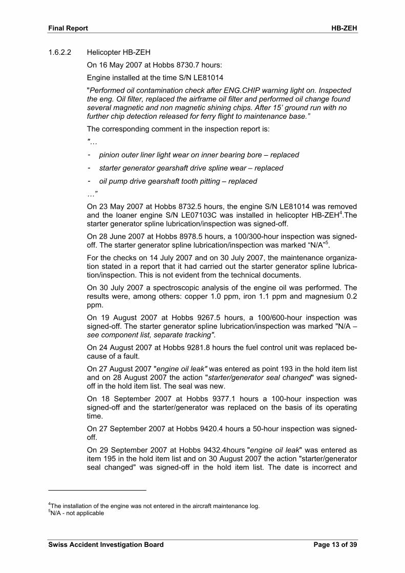
1.6.2.2 Helicopter HB-ZEH
On 16 May 2007 at Hobbs 8730.7 hours:
Engine installed at the time S/N LE81014
"Performed oil contamination check after ENG.CHIP warning light on. Inspected the eng. Oil filter, replaced the airframe oil filter and performed oil change found several magnetic and non magnetic shining chips. After 15’ ground run with no further chip detection released for ferry flight to maintenance base.”
The corresponding comment in the inspection report is:
"…
- pinion outer liner light wear on inner bearing bore – replaced
- starter generator gearshaft drive spline wear – replaced
- oil pump drive gearshaft tooth pitting – replaced
…”
On 23 May 2007 at Hobbs 8732.5 hours, the engine S/N LE81014 was removed and the loaner engine S/N LE07103C was installed in helicopter HB-ZEH4.The starter generator spline lubrication/inspection was signed-off.
On 28 June 2007 at Hobbs 8978.5 hours, a 100/300-hour inspection was signed-off. The starter generator spline lubrication/inspection was marked “N/A”5.
For the checks on 14 July 2007 and on 30 July 2007, the maintenance organiza-tion stated in a report that it had carried out the starter generator spline lubrica-tion/inspection. This is not evident from the technical documents.
On 30 July 2007 a spectroscopic analysis of the engine oil was performed. The results were, among others: copper 1.0 ppm, iron 1.1 ppm and magnesium 0.2 ppm.
On 19 August 2007 at Hobbs 9267.5 hours, a 100/600-hour inspection was signed-off. The starter generator spline lubrication/inspection was marked "N/A – see component list, separate tracking".
On 24 August 2007 at Hobbs 9281.8 hours the fuel control unit was replaced be-cause of a fault.
On 27 August 2007 "engine oil leak" was entered as point 193 in the hold item list and on 28 August 2007 the action "starter/generator seal changed" was signed-off in the hold item list. The seal was new.
On 18 September 2007 at Hobbs 9377.1 hours a 100-hour inspection was signed-off and the starter/generator was replaced on the basis of its operating time.
On 27 September 2007 at Hobbs 9420.4 hours a 50-hour inspection was signed-off.
On 29 September 2007 at Hobbs 9432.4hours "engine oil leak" was entered as item 195 in the hold item list and on 30 August 2007 the action "starter/generator seal changed" was signed-off in the hold item list. The date is incorrect and
4The installation of the engine was not entered in the aircraft maintenance log. 5N/A - not applicable

Final Report HB-ZEH
Swiss Accident Investigation Board Page 14 of 39
should read 30 September 2007. On this occasion the seal which was removed on 28 August 2007 was re-fitted and the spring was shortened by approx. 8 mm.
On the day of the accident, the AD 2004 - 269 M/R grip inspection SB 109 and AD 1999/643 clutch inspection AFM 3-7 were signed-off.
Some of the maintenance work was poorly and incompletely documented.
1.6.3 Design features and certification basis of helicopter K-1200
The K-1200 helicopter was developed by the Kaman company as a transport helicopter. The rotorcraft flight manual (RFM) states in this regard: “The K-1200 is built specifically for repetitive lifting operations. The simplified design uses tradi-tional aircraft materials engineered for maximum load bearing strength. The sin-gle-seat configuration offers maximum pilot visibility in all directions. Controls and instruments are arranged to be compatible with vertical reference flight require-ments. The pilot’s seat is a high-energy absorbing unit supported by reinforced structure.”
Type certification according to FAR 21 and FAR 27 was granted by the Federal Aviation Administration (FAA) on 30 August 1994.
1.6.4 Engine
1.6.4.1 Description of the system
The K-MAX helicopter is equipped with a "Honeywell T5317A-1" twin-shaft tur-bine engine. The engine consists of a two-stage free power turbine (N2) and a two-stage gas producer turbine (N1) which drives a combined axial and centrifu-gal compressor.
Figure 1 – Cross-sectional view of a T53 engine
N1 is controlled by the pilot's twist-grip throttle on the collective via various con-trol linkages to the fuel control unit – FCU.
A constant N2 RPM is achieved by means of a varying N1 RPM depending on the load.

Final Report HB-ZEH
Swiss Accident Investigation Board Page 15 of 39
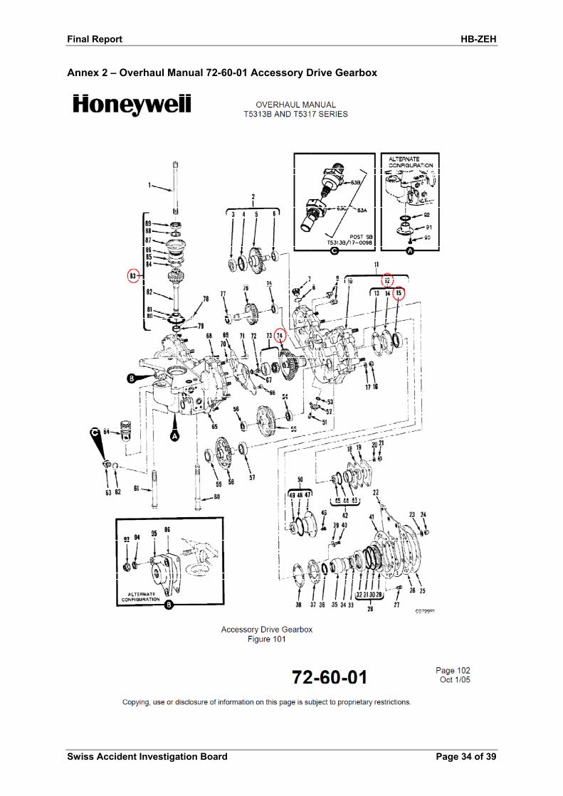
1.6.4.2 Description and function of the N1 accessory drive gearbox
The N1 accessory drive gearbox is mounted at the six o'clock position of the air inlet housing. It is driven via the accessory drive shaft, which connects the N1 stage of the engine via the outer pinion gearshaft assembly to the accessory drive gear assembly (see Figures 1 and 2).
Figure 2 – Depiction of the T53 engine and the position of the N1 accessory drive gearbox(see arrow)
The oil pump, fuel control unit, gas producer tachometer and starter/generator are connected to the N1accessory drive gearbox. These accessory drives are driven by the accessory drive gear assembly.
At the bottom of the housing, a magnetic chip detector is installed.
A detailed description of the components is provided in the Annex.
1.6.5 Information in the Rotorcraft Flight Manual
1.6.5.1 General information on emergency procedures:
“General
The procedures outlined in this section deal with the common types of emergen-cies; however, the actions taken in each actual emergency must relate to the complete situation. Extraordinary circumstances such as compound emergencies may require departures from the normal corrective procedures used for any spe-cific emergency.
Throughout this section, the terms “land immediately,” “land as soon as possible,” and “land as soon as practical” are used to reflect the degree of urgency with which a landing must be made.
1. LAND IMMEDIATELY – Self explanatory.
2. LAND AS SOON AS POSSIBLE – Land at the nearest site at which a safe landing can be made.
3. LAND AS SOON AS PRACTICAL – Extended flight is not recommended. The landing site and duration of the flight are at the discretion of the pilot.

Final Report HB-ZEH
Swiss Accident Investigation Board Page 16 of 39
Many of the malfunctions described in this section will be indicated by the lighting of warning or caution lights, the master caution light, and in some cases, a tone in the headset. Whenever a caution light goes on, the RESET pushbutton should be depressed to turn the master caution light off and reset it for another condi-tion. An audio tone can be eliminated and reset for another condition by pressing the RESET pushbutton.
Any unusual change in aircraft noise, vibrations, or flight characteristics should be investigated immediately to determine an appropriate course of action. If the cause and procedure are not immediately obvious, a power–on landing should be made as soon as possible. External load operations should be discontinued, in-cluding jettison as required, until the aircraft has been thoroughly inspected and returned to normal service.”
1.6.5.2 Cockpit indicating lights
“The following tables provide cockpit indicating light definitions and scenarios:
1. Cockpit master warning and caution lights – Table 4–1.
2. Cockpit indicating lights requiring landing as soon as possible – Table 4–2.
3. Cockpit indicating lights requiring landing as soon as practical – Table 4–3.
4. Cockpit indicating lights requiring immediate pilot action – Table 4–4.
5. Cockpit advisory lights – Table 4–5.
(….)
Table 4–2: Cockpit indicating lights requiring landing as soon as possible
Legend Meaning
XMSN CHIP Possible transmission deterioration. Press FUZZ BURN. If light continues, land and inspect.
XMSN PRESS Low transmission oil pressure. Land and inspect.
XMSN TEMP High transmission oil temperature. Reduce transmis-sion load; land and inspect.
XMSN BYPASS Impending oil filter bypass. Land and inspect.
XMSN LOW Transmission oil level low. Land and inspect.
ENG CHIP Possible engine deterioration. Press FUZZ BURN. If light continues, land and inspect.
ENG PRESS Low engine oil pressure. Land and inspect.
(….)”

Final Report HB-ZEH
Swiss Accident Investigation Board Page 17 of 39
1.6.5.3 Chip Detection System
“Chip detection systems are installed in the engine and transmission lubricating systems to provide early detection and a visual warning of possible component deterioration/failure.
The engine oil system employs a quick–disconnect type chip detector at the base of the engine oil tank and a threaded type chip detector on the lower part of the engine. Detection of metal particles by either of these detectors results in illumi-nation of the MAST CAUT and ENG CHIP warning lights.
The transmission oil system employs a quick–disconnect type chip detector at the base of the transmission oil tank and two quick–disconnect type chip detec-tors located on the left and right sumps of the transmission. Detection of metal particles by any of the three detectors will result in illumination of the MAST CAUT and XMSN CHIP warning lights.
A chip burn–off system is installed to remove fuzz or small ferrous particles caused by normal wear that have caused illumination of the chip warning lights. A momentary–type switch labelled FUZZ BURN is located on the lower left part of the main instrument panel to activate this system. When the fuzz–burn switch is depressed a short–duration pulse of current is provided to all chip detectors. This will normally cause the MAST CAUT and appropriate CHIP WARNING lights to extinguish if the fault was only fuzz or small ferrous particles caused by normal wear.”
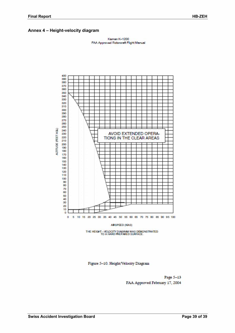
1.6.5.4 Height-Velocity Diagram
“The Height–Velocity diagram (….) uses factors of airspeed and height above ground to represent areas where aircraft damage or injury may occur in the event that an autorotation has to be accomplished. The clear areas shown represent regions where extended operations should be avoided. They do not represent limitations. The aircraft gross weight used to define the diagram was 6500 lbs.”
The corresponding diagram is shown in Annex 4.
1.6.6 Information in the engine maintenance manual
1.6.6.1 Procedures in the event of lubrication oil contamination
The engine maintenance manual, section 79-30-01, describes the following with regard to inspection of the chip detector:
„Inspection/Check
A. Inspect chip detector for build-up of metallic particles.
(1) A small amount of metallic powder is normal and acceptable.
(2) Course chips or an excessive amount of metallic powder are symptoms of possible failure. This condition requires a lubrication system contamination trouble shooting procedure (72-00-006).
B. Inspect chip detector and threaded hole in gearbox for damaged threads. Replace chip detector if stripped or damaged beyond repair.”
6Maintenance Manual T5313B and T5317 Series 72-00-00 Page 120 -122 (see Annex 3)

Final Report HB-ZEH
Swiss Accident Investigation Board Page 18 of 39
1.7 Meteorological information
1.7.1 General information
The information in sections 1.7.2 and 1.7.3 was provided by MeteoSwiss.
The information in section 1.7.5 is based on eyewitness observations.
1.7.2 General meteorological situation
A zone of high pressure centred over central Europe was moving slowly east-ward. In the process, somewhat milder but more humid air was being conveyed by a high-altitude south-westerly airflow towards the area of the Alps.
1.7.3 Weather at the time and location of the accident
The following information on the weather at the time and location of the accident is based on a spatial and chronological interpolation of the observations of sev-eral weather stations.
Weather/clouds 5/8 at approx. 30 000 ft AMSL (Cirrus spissatus)
Visibility Approx. 25 km
Wind South-west at 2-4 kt
Temperature/dewpoint 14 °C/08 °C
Atmospheric pressure QNH LSZH 1021 hPa; LSZC 1021 hPa; LSZA 1021 hPa
Hazards None detectable
1.7.4 Astronomical information
Position of the sun Azimuth: 166 ° Elevation: 39 °
Lighting conditions daylight
1.7.5 Weather according to eyewitness reports
Both the flight assistant on the ground and the aircraft mechanic confirmed very good visibility, scattered cloud and a light wind.
1.8 Aids to navigation
Not applicable.
1.9 Communication
Radio communications between the pilot and the flight assistant on the ground took place in an orderly fashion and without difficulties up to the time of the acci-dent.
1.10 Aerodrome information
Not applicable.
1.11 Flight recorders
The helicopter was fitted neither with a flight data recorder nor a cockpit voice re-corder. These were not prescribed.
The exceedance flag was black for torque, NG, EGT and load indicators, i.e. in a normal state.

Final Report HB-ZEH
Swiss Accident Investigation Board Page 19 of 39
1.12 Wreckage and impact information
1.12.1 Accident site
The site of the accident was in hilly, sparsely wooded and steep terrain at approx. 1320 m AMSL (see figures 3 and 4).
Figure 3 – Aerial photograph of the accident site with wreckage and load pick-up area
1.12.2 Impact
The impact of the helicopter was violent. This is evident from the deformation of the robust frontal structure. Part of the left section of the main gear dug into the earth and stabilised the wreckage. The rotor blades were destroyed on impact with the ground.
Figure 4– Final position of the wreckage

Final Report HB-ZEH
Swiss Accident Investigation Board Page 20 of 39
1.12.3 Wreckage
1.12.3.1 General findings
The lap and shoulder belts were worn and withstood the stress.
A general visual examination of the helicopter gave no indications of pre-existing defects.
The following findings were made on the wreckage:
Battery OFF Fuel/oil switch ON Generator switch ON Particle separator switch OFF Emergency governor guard down OFF
The twist grip was in the FLY detent position.
The KAflex drive shaft coupling and the clutch assembly were intact.
1.12.3.2 Initial examinations of the engine
The engine was removed from the helicopter and initial examinations gave the following findings:
The power turbine could be rotated freely by hand.
The N1 accessory drive gearbox was removed. It was found that the ac-cessory drives could not be driven by turning the accessory drive shaft. In particular, axial play in the accessory drive gear assembly was found.

Final Report HB-ZEH
Swiss Accident Investigation Board Page 21 of 39
Figure 5 – Engine chip detector with chips
The engine chip detector was re-moved and revealed a large quantity of metallic chips.
Figure 6 – Starter/generator drive pad on the N1 accessory drive gearbox
The internal splines of the starter/generator drive in the acces-sory drive gearbox exhibited wear and traces of oil.
Figure 7 – View of damaged accessory drive gear assembly
After removal of the outer pinion gearshaft assembly, the accessory drive gear assembly was visible. The bevel gear is severely damaged and shows plastic deformation.

Final Report HB-ZEH
Swiss Accident Investigation Board Page 22 of 39
Figure 8 – Outer pinion gearshaft assembly (counterpart to Figure 7)
The bevel pinion of the outer pinion gearshaft assembly exhibited pro-nounced damage and plastic defor-mation.
Figure 9–Bevel gear accessory drive gear assembly in disas-sembled state with damaged bearing and grooves on the inner race of the bearing
After removal of the accessory drive gear assembly from the accessory drive gearbox, the damaged ball bearing (P/N 91547-SOCN-2-300-013-03 CDA-99193; S/N 021991421878) was visible. Evident are the grooves and elongated, oval boreholes in the bearing cage.
Figure10 – Outer race of the bearing with grooves
The outer bearing race also has grooves.

Final Report HB-ZEH
Swiss Accident Investigation Board Page 23 of 39
1.13 Medical and pathological information
The pilot suffered minor injuries to his upper and lower extremities.
1.14 Fire
Fire did not break out.
1.15 Survival aspects
The accident was survivable thanks to the robust construction of the helicopter.
1.16 Tests and research
1.16.1 Forensic investigations
The forensic investigation of the instruments and displays yielded the following results:
The gas producer RPM (NG) indicator was slightly above 30%.
The ammeter exhibited a smeared mark from approx. 75 A down to just below 0 A.
The engine oil pressure gauge exhibited a smeared mark from approxi-mately 40 psi to just below 0.
The main gearbox oil pressure indicator exhibited a mark at approx. 31 psi.
The "MASTER CAUTION" and "MAST CAUT" warning lamps were acti-vated.
On the caution panel, the "XMSN PRESS" and "GENERATOR" lamps were activated. The coiled filaments of the "ENG PRESS" warning light were still located in the guides of the filament supports, but are changed slightly compared to new lamps. The "ENG CHIP" lamp showed no marks.
1.16.2 Dismantling of the engine for inspection
Due to the large amount of metal chips found in the N1 accessory drive gearbox, the engine was disassembled for inspection and examined.
“Summary of inspection:
The engine was disassembled into its main subassemblies and visually inspected in “dirty condition”. The oil wetted parts of the engine were in a good and healthy condition. Neither in the reduction gearbox and the front bearing housing nor in the hot section bearing areas was any abnormal wear or damage discovered. The main bearings and the reduction gearbox gears and bearings were found without visual damage. No oil leakages could be recognized at any sealing. Sev-eral parts in the hot section were severely burned and damaged. Particularly the combustion chamber, the 1st stage gas producer nozzle, 1st stage turbine blades and 2nd stage gas producer nozzle were exposed to excessive heat. Although the above mentioned hot section components were severely damaged all those damages are not uncommon for a T53-17A1 engine used in a K-MAX operation. The worn combustion chamber deflector flange as well as the worn combustion chamber liner flange indicate (or may even have caused) an increased level of engine vibrations. The type of wear at these parts is known but not very common.
(….)

Final Report HB-ZEH
Swiss Accident Investigation Board Page 24 of 39
The test assembly of the accessory drive gearbox was done with the mixture of new and original parts. A statement regarding the correct shimming during last repair or overhaul is not possible.”
1.16.3 Examination of the FCU
A functional test of the fuel control unit (FCU p/n: 1-170-240-93; S/N: 32AS11619) and the overspeed governor (p/n: 1-160-850-25; S/N: 9A0Y1833) was carried out.
“The test result can be summarized as follows. The “as received“ FCU settings were out of limits i.a.w. the valid Overhaul Manual. The discovered discrepancies are typical for installed FCU's and related to minor adjustments that have to be done during the engine test or after engine installation into the helicopter.”
1.16.4 Examination of the oil pump
The oil pump installed on the engine of the helicopter involved in the accident was a Lear Romec RG17350D vane pump.
First, the static breakaway torque and the un-loaded torque were measured.
The pump was then disassembled and examined for wear, internal damage and residues or foreign objects.
Findings:
The measured values were consistently below the limits.
Neither wear nor residues were detected.
1.16.5 Examination of the starter/generator
The starter/generator was examined after the accident. The following findings were made:
The concentricity of the drive shaft was 0.05 mm.
The test as a generator was successful and showed that the unit runs very quietly.
The unit was internally covered with oil and was in a functional condition.
The input/output end of the starter/generator drive shaft was measured. The splined shaft exhibited no wear; the measured values were within the permissible limits.
1.16.6 Examination of components of the N1 accessory drive gearbox
The damaged bevel pinion, bevel gear and the ball bearing of the accessory drive gearbox N1 were examined in detail. Those parts which are important for mounting the damaged components were also examined.
1.16.6.1 Conformity of the components
On the damaged lower bevel gear P/N 1-080-310-01 the diameters of the bearing seat and the intermediate shoulder distance were measured. The gearbox hous-ing in the area of the bevel gear bearing, the shimming of the ball bearing and the width of the bearing races were also measured. Taking into account the maxi-mum permissible dimensional variation according to the drawing with regard to the outer and inner race of the bearing, it can be ruled out that the bearing of the lower bevel gear shaft was fitted axially braced.

Final Report HB-ZEH
Swiss Accident Investigation Board Page 25 of 39
All the measured dimensions are in conformity with the drawing. Because of the damage to the teeth it was not possible to determine whether the tooth contact pattern was correct before the accident.
The material composition of the bevel gear P/N 1-080-310-01, bevel pinion P/N 1-080-320-01 and ball bearing P/N 2-300-013.03 were examined in detail. Ac-cording to the material analysis, the material of the bevel pinion can be classified as A304 (9310 H) ASTM, and that of the bevel gear as 6263 H (AMS). Both are high-performance steels which are often used for the production of gears.
From the examination of the material of the inner race, the outer race, the balls and the cage of the damaged bearing, it is evident that all these components are composed of standard material of the appropriate quality. The hardness meas-urements on the inner race, outer race and balls yielded values of 61 HRC to 63 HRC. These values are also in conformity.
The chips found on the chip detector in the N1 accessory drive gearbox and in the oil sump were also examined. The chips consist of the same material as the gears – so they are presumably fragments of these gears.
1.16.6.2 Damage
On the bevel pinion, it was primarily the teeth which were damaged. The material of the tooth tip exhibited plastic deformation across its entirety and had partially broken off; the base and the flanks of the teeth in the area of the root were not damaged.
No damage could be found on the bevel pinion shaft bearing.
On the bevel gear, the teeth and the internal splines on the output side of the shaft – which transfers torque to the starter/generator – were damaged.
The smaller of the two bearings by which the bevel gear shaft is supported – a roller bearing which does not carry axial loads – did not exhibit any damage. The larger bearing – a ball bearing which supports the bevel gear shaft in the radial and axial direction – was severely damaged.
The most pronounced damage was exhibited by the raceway of the inner race of the bearing, the balls and the cage. The wear of the raceway of the outer race was less pronounced. The SEM7 examination of the ball bearing raceways and the balls revealed evidence of pitting8 and fatigue, i.e. the damage and wear on the ball bearing is due to fatigue.
1.17 Organisational and management information
1.17.1 The operator – Eagle Helicopter AG
Eagle Helicopter AG is an aerial work operator and employed some 30 employ-ees. The company was active in the areas of logging, specialist logging, con-struction and transport. A Kaman K-1200 and a Eurocopter AS350 were used for these purposes.
7SEM - scanning electron microscope
8 pitting - break-out of material and micro-fissures near to the surface

Final Report HB-ZEH
Swiss Accident Investigation Board Page 26 of 39
1.17.2 Maintenance Organization – RUAG Aviation
RUAG Aviation is a company in the aviation industry based in Emmen, with ten other locations in Switzerland and two in Germany. Its main activities include the maintenance and modification of aircraft, helicopters, drones, guided missiles and air defence systems.
1.17.3 Organisation of the maintenance of helicopter HB-ZEH
Since the operator did not have a JAR-145 Maintenance Organization for the type K-1200 helicopter, a corresponding contract was agreed with RUAG Avia-tion.
The aircraft mechanic referred to in section 1.5.2 was listed in the MOE9 of RUAG Aviation.
9MOE - maintenance organisation exposition

Final Report HB-ZEH
Swiss Accident Investigation Board Page 27 of 39
2 Analysis
2.1 Technical aspects
2.1.1 Damage to the teeth of the bevel gear
As a result of the damage to the ball bearing the bevel gear shaft was no longer supported axially and was displaced axially as force was transferred by the bevel pinion. As a result of this displacement, there was a reduction in the tooth en-gagement, plastic deformation of the tips of the teeth and broken-off material par-ticals. The progressive wear of the ball bearing race meant that the two gears were no longer engaged, resulting in a loss of function of the FCU and shut-off of the engine; this subsequently led to the helicopter accident.
2.1.2 Bearing wear
The bearing wear which was found is a classic example of fatigue of the races and balls as a result of pitting – a form of fatigue wear.
Such wear is typical when a bearing is at the end of its life. This is affected by the operating conditions, such as for example the load on the bearing, the lubricant, the amount of contaminants in the lubricant, the bearing material, etc.
According to the results of the investigation, it must be assumed that the load on the bearing was too high and/or the lubricant had an excessively high amount of foreign particles.
It is evident from the maintenance records that 1480 operating hours before the accident, the N1 accessory drive gearbox was repaired, and the ball bearing as well as the internally splined bevel gear shaft were fitted as new parts. This took place 1865 operating hours after an overhaul of the N1 accessory drive gearbox. This means that, the installed ball bearing was well short of the required service life of 5000 hours.
Any existing minor concentricity misalignment in the splined shaft end with re-spect to the centring spigot assembly of the starter/generator will cause a con-siderable increase in the load on the ball bearing of the bevel gear, which could lead to premature failure of the bearing.
It could not be determined whether the starter/generator installed until 64 hours before the accident occured had a concentricity misalignment.
2.1.2.1 Bevel gear shaft bearings
The bevel gear shaft is retained by a roller bearing and a ball bearing. The roller bearing is subjected to radial loading and the ball bearing is subjected to a radial and an axial load. The ball bearing is a single-row radial bearing which according to its designation is designed primarily for radial loads. Axial loads on this type of bearing are permissible to a limited extent. From the available data, it was not possible to assess whether the bevel gear shaft ball bearing was sufficiently di-mensioned to cope with the service loads.
Final Report HB-ZEH
Swiss Accident Investigation Board Page 28 of 39
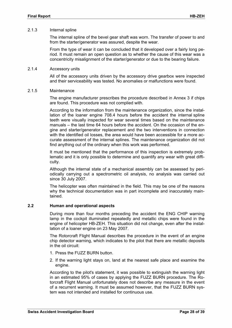
2.1.3 Internal spline
The internal spline of the bevel gear shaft was worn. The transfer of power to and from the starter/generator was assured, despite the wear.
From the type of wear it can be concluded that it developed over a fairly long pe-riod. It must remain an open question as to whether the cause of this wear was a concentricity misalignment of the starter/generator or due to the bearing failure.
2.1.4 Accessory units
All of the accessory units driven by the accessory drive gearbox were inspected and their serviceability was tested. No anomalies or malfunctions were found.
2.1.5 Maintenance
The engine manufacturer prescribes the procedure described in Annex 3 if chips are found. This procedure was not complied with.
According to the information from the maintenance organization, since the instal-lation of the loaner engine 708.4 hours before the accident the internal spline teeth were visually inspected for wear several times based on the maintenance manuals – the last time 64 hours before the accident. On the occasion of the en-gine and starter/generator replacement and the two interventions in connection with the identified oil losses, the area would have been accessible for a more ac-curate assessment of the internal splines. The maintenance organization did not find anything out of the ordinary when this work was performed.
It must be mentioned that the performance of this inspection is extremely prob-lematic and it is only possible to determine and quantify any wear with great diffi-culty.
Although the internal state of a mechanical assembly can be assessed by peri-odically carrying out a spectrometric oil analysis, no analysis was carried out since 30 July 2007.
The helicopter was often maintained in the field. This may be one of the reasons why the technical documentation was in part incomplete and inaccurately main-tained.
2.2 Human and operational aspects
During more than four months preceding the accident the ENG CHIP warning lamp in the cockpit illuminated repeatedly and metallic chips were found in the engine of helicopter HB-ZEH. This situation did not change, even after the instal-lation of a loaner engine on 23 May 2007.
The Rotorcraft Flight Manual describes the procedure in the event of an engine chip detector warning, which indicates to the pilot that there are metallic deposits in the oil circuit:
1. Press the FUZZ BURN button.
2. If the warning light stays on, land at the nearest safe place and examine the engine.
According to the pilot's statement, it was possible to extinguish the warning light in an estimated 95% of cases by applying the FUZZ BURN procedure. The Ro-torcraft Flight Manual unfortunately does not describe any measure in the event of a recurrent warning. It must be assumed however, that the FUZZ BURN sys-tem was not intended and installed for continuous use.

Final Report HB-ZEH
Swiss Accident Investigation Board Page 29 of 39
The recurring loss of oil in the immediate vicinity of the worn bevel gear shaft bearing, the abnormal noise during the engine starting procedure and the re-peated illumination of the ENG CHIP warning lamp were indicators of a mechani-cal problem in the N1 accessory drive gearbox. Insufficient attention was paid to these indications. Instead, top priority was placed on the fulfilment of the work assignment. The evident indications of a defect in the engine were not appropri-ately addressed, apparently as a result of previous experience with regard to CHIP ENG warnings. This appears to be incomprehensible, particularly in the light of the exposed situation of the helicopter during the cargo flight.
This becomes clearly evident when the main envelope of the helicopter's opera-tion on cargo flights is compared with the H/V diagram (Annex). The operation of the helicopter on cargo flights is located almost exclusively within the zones to be avoided, shown shaded in white on the graph.
An engine failure in such a flight phase makes it impossible to carry out a suc-cessful autorotation and inevitably leads to serious consequences.

Final Report HB-ZEH
Swiss Accident Investigation Board Page 30 of 39
3 Conclusions
3.1 Findings
3.1.1 Technical aspects
The aircraft was licensed for VFR flight.
Both the mass and centre of gravity of the rotorcraft at the time of the acci-dent were within the permitted limits according to the RFM.
The investigation produced indications of pre-existing technical faults which caused the incident.
On 18 September 2007 at Hobbs 9377.1 hours, a 100-hour inspection was signed-off and the starter/generator was replaced on the basis of its operat-ing time.
The last condition check by the FOCA took place on 27 December 2006.
On 23 May 2007 at Hobbs 8732.5 hours, engine S/N LE81014 was re-moved and the loaner engine S/N LE07103C was installed in helicopter HB-ZEH. The starter generator spline lubrication/inspection was signed-off.
For more than the four months preceding the accident, chips were repeat-edly found in the engine and were also indicated to the pilot by means of the ENG CHIP warning lamp in the cockpit. The pilot repeatedly applied the FUZZ BURN procedure.
After the accident it was possible to rotate the power turbine freely by hand.
The N1 accessory drive gearbox was disassembled. Subsequently it was found that the accessory gears could not be driven by rotating the acces-sory drive shaft. In particular, axial play was detected in the accessory drive gear assembly.
On the bevel pinion, it was primarily the teeth which were damaged. The material of the tooth tip exhibited plastic deformation across their entirety and had partially broken off; the base and the flanks of the teeth in the area of the root were not damaged.
On the bevel gear, the teeth and the internal splines on the output side of the shaft – which transfers power to the starter/generator – were damaged.
The smaller of the two bearings which support the bevel gear shaft– a roller bearing with no load transfer in the axial direction – did not exhibit any damage.
The larger bevel gear shaft bearing – a ball bearing which transfers loads in the radial and axial direction – was severely damaged. The most pro-nounced damage was exhibited by the raceway of the inner bearing race, the balls and the cage. The wear of raceway of the outer race was less pronounced. The examination of the raceways and the balls indicated pit-ting and fatigue, i.e. the wear on the ball bearing is attributable to fatigue.
1480 operating hours before the accident, the N1 accessory drive gearbox was repaired, and the ball bearing as well as the internally splined bevel gear shaft were fitted as new parts. This took place 1865 operating hours after an overhaul of the N1 accessory drive gearbox. This means that the installed ball bearing was well short of the required service life of 5000 hours.

Final Report HB-ZEH
Swiss Accident Investigation Board Page 31 of 39
The recurring loss of oil in the immediate vicinity of the worn bevel gear shaft bearing, the abnormal noise during the engine starting procedure and the repeated illumination of the ENG CHIP warning lamp were indicators of a mechanical problem in the N1 accessory drive gearbox.
The evident indications of a defect in the engine were not appropriately ad-dressed, apparently as a result of previous experience with regard to CHIP ENG warnings.
The procedure prescribed by the engine manufacturer in the event that chips are found was not observed.
The maintenance work was in part inaccurately and incompletely docu-mented.
3.1.2 Crew
The pilot held the necessary licences for the flight.
The lap and shoulder belts were worn and withstood the stress.
There are no indications of the pilot suffering health problems during the flight involved in the accident.
3.1.3 History of the flight
During the starting procedure before the flight involved in the accident, the pilot and the technical director noticed an anomaly in the form of an un-known noise.
During engine acceleration up to "Flight" RPM, the ENG CHIP lamp illumi-nated. The chip detector was then removed and checked by the technical director. The pilot stated that after this intervention the ENG CHIP warning light illuminated once or twice and that he was able to extinguish it by ap-plying the FUZZ BURN procedure.
After consultation with the technical director, the pilot decided to carry out the envisaged working flight.
Over the next 30 minutes timber was transported. During this time, the pilot twice noticed that the ENG CHIP warning lamp illuminated. It was possible to clear the two warnings by applying the FUZZ BURN procedure.
During the last approach in the direction of the timber unloading area, the pilot noticed that the ENG CHIP warning lamp illuminated again. He set down the load and flew back towards the pick-up point.
In the approach to the pick-up point, a distinct loss of RPM was noticed.
The pilot activated the longline emergency release in order to make an emergency landing in the direction of flight.
The helicopter collided with the terrain approx. 100 metres west of the pick-up point on a sloping hillside and was destroyed.
Final Report HB-ZEH
Swiss Accident Investigation Board Page 32 of 39
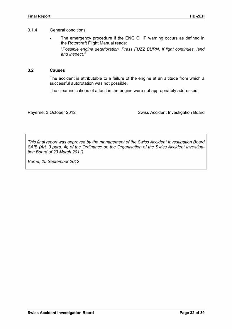
3.1.4 General conditions
The emergency procedure if the ENG CHIP warning occurs as defined in the Rotorcraft Flight Manual reads:
"Possible engine deterioration. Press FUZZ BURN. If light continues, land and inspect.”
3.2 Causes
The accident is attributable to a failure of the engine at an altitude from which a successful autorotation was not possible.
The clear indications of a fault in the engine were not appropriately addressed.
Payerne, 3 October 2012 Swiss Accident Investigation Board
This final report was approved by the management of the Swiss Accident Investigation Board SAIB (Art. 3 para. 4g of the Ordinance on the Organisation of the Swiss Accident Investiga-tion Board of 23 March 2011).
Berne, 25 September 2012

Final Report HB-ZEH
Swiss Accident Investigation Board Page 33 of 39
Annex 1
Final Report HB-ZEH
Swiss Accident Investigation Board Page 34 of 39
Annex 2 – Overhaul Manual 72-60-01 Accessory Drive Gearbox

Final Report HB-ZEH
Swiss Accident Investigation Board Page 35 of 39

Final Report HB-ZEH
Swiss Accident Investigation Board Page 36 of 39
Annex 3 – Maintenance Manual T5313B and T5317 Series 72-00-00 Page 120 -122

Final Report HB-ZEH
Swiss Accident Investigation Board Page 37 of 39

Final Report HB-ZEH
Swiss Accident Investigation Board Page 38 of 39
Final Report HB-ZEH
Swiss Accident Investigation Board Page 39 of 39
Annex 4 – Height-velocity diagram