Embed Size (px)
Citation preview

1
King Fahd University of Petroleum & Minerals
College of Engineering Science
Electrical Engineering Department
EE 399
Summer Training
At
Final Report
Student Name: Mamdouh Al Harbi
ID#: 200624160

2
Table of Contents
I. ABSTRACT ................................................................................ 3
II. INTRODUCTION ....................................................................... 4
III. CABLES ...................................................................................... 4
IV. JEDDAH CABLES COMPANY (JCC) .................................... 5
V. ENGINEERING PROJECTS DEPT. ......................................... 7
VI. MANUFACTORING PROCESS .............................................. 8
VII. CABLE DESIGNING .............................................................. 12
VIII. CABLE DESIGN PROBLEM ................................................. 15
IX. MATERIALS USED ................................................................ 20
X. WATER BLOCKING TECHNIQUES .................................... 21
XI. CABLE TESTING ................................................................... 22
XII. CONCLUSION ........................................................................ 22
XIII. TABLE OF CABLE MANUFACTURING FIGURES………23
XIV. ATTATCHMENTS .................................................................. 26

3
I. ABSTRACT
This report discusses the summer training program at Jeddah Cables Company
during the period from 3rd
July 2010 to 27th
August 2010. It states briefly the
importance of cables and what factors are considered in cable designing process.
It shows a brief background about the place of training; Jeddah Cable Company. It
mentions some facts about the department that was responsible for the training
program. The report describes the process of cable manufacturing at Jeddah Cable
Company. Also, it explains the process of designing cables in accordance with
international standards and specifications. As an example of many design
problems performed during the period of training, the report contains a cable
design problem. Furthermore, the report explains some cable manufacturing issues
studied during the training including materials used, water blocking techniques
and cable testing.

4
II. INTRODUCTION
As part of the Bachelor degree for the Science Engineering students, a summer
training program for 8 weeks is required to have a taste of the practical experience
for engineers on the job. The training program was during the period from 3rd
July
2010 to 27 August 2010 at Jeddah Cables Company – Jeddah, Saudi Arabia. This
program was assigned to the Engineering Projects Department (EPD) and
supervised by the Engineering Projects Manager. Engineers at EPD are
responsible for designing cables according to the customer specifications and
some international standards. The purpose of this report is to show the experience
at Jeddah Cables Company during the summer training period.
III. CABLES
Electricity directly serves mankind, and the electric cables form the connecting
links between pieces of electrical apparatuses or machines to transmit power or
signals. A well engineered cable is the product of combined efforts of many
people. The cable should be capable of doing the work for which it is designed

5
with a reasonable margin for voltage rise or current overload. Furthermore, the
cable should be shielded to avoid danger to people, apparatuses and cables
themselves.
Several factors affect choice of a cable including the size of the conductor, lifetime
and insulation requirements and conditions. Understanding the basic elements of
electrical theory and their applications is mandatory to study of the design and the
usage of cables.
Cables can be classified based on the usage, the construction, the shape, the
operating voltage, or other considerations.
IV. JEDDAH CABLES COMPANY (JCC)
Jeddah cable Company is one of the leading manufacturers of electric cables
and wires in Saudi Arabia. It contributes to cables industry using five plants in
Jeddah which are dedicated to different jobs. These plants work together to
produce five different types of cables to meet the markets demands in Saudi
Arabia, Qatar and the United Arab Emirates. Jeddah Cables Company consists
of nine main departments working cooperatively to achieve the company
objectives.
4.1. JCC Plants:
4.1.1 Copper Rod Plant:
This plant produces copper rods using continuous casting technique
with copper cathodes. This is done using cathode plates that are
imported from mineral manufacturers. These plates are placed in a
furnace to be fused and then shaped to cylindrical rod with the
following characteristics:
Diameter of 8 ± 0.38 mm.

6
Tensile strength of 250 N/mm2.
Elongation ≥ 30%.
Resistance of 0.01222 Ω/m
100% conductivity as per IACS (International Annealed Copper
Standard).
All of these specifications are measured continuously in the
Copper Laboratory at the factory.
4.1.2 PVC Granules Plant:
This plant manufactures various types of PVC compound to be used
for insulation, bedding and sheathing the cables.
4.1.3 Low Voltage Cables Plant:
This plant manufactures cables that have size range from 0.5 mm2 to
800 mm2 and voltage raring up to 0.6 kV (phase voltage) or 1 kV
(line voltage). These cables are classified into:
Building wires.
Control Cables.
Low Voltage Power Cables.
Instrumentation cables.
Overhead lines.
4.1.4 Medium-High Voltage Cables Plant:
This plant manufactures cables that have size range from 16 mm2 to
630 mm2 and voltage raring up to 18 kV (phase voltage) or 30 kV
(line voltage).
4.1.5 Wooden Real Plant:
To manufacture wooden battens and drums used for storing and
shipping cables.
4.2. JCC Products:
1) Low voltage power cables.
2) Medium voltage power cables.
3) Overhead lines.
4) Control cables.

7
5) Indoor Cables.
4.3. Clients:
The Jeddah Cable Company has a wide range of clients for its cables
market both locally and regionally.
4.4. JCC Departments:
JCC internal structure is made up of a number of interrelated
departments, these include: Production, Engineering and Quality
Assurance, Services and Training, Business Development, Finance,
Management of Information Systems, Purchasing, Human Resources
and Administration and Safety.
V. EHGINEERING PROJECTS DEPT.
The Engineering Projects department at JCC is the heart of the company. It has
many duties as following:
It has a team of engineers who are responsible for designing
cables based on many international criteria and standards which
consider many cable phenomena such as resistance, inductance,
conductance, capacitance, insulation, ampacity and some
electromagnetic issues. Also, they have to consider the cost of
raw materials used to manufacture cables to design high-quality,
low cost cables.
It ensures that the technical aspects of all production orders
submitted by the sales department are correct.
It receives from customers, such as SEC, some feedback related
to the cables they have purchased to fix cables defects and solve
their problems from engineering point of view. The Engineering
Project department
Its engineers represent the company at seminars, conference,
committees and so on.
It has a number of supportive duties to other departments.

8
VI. MANUFACTURING PROCESS
Cable manufacturing process involves a broad range of complexity depending
on the cable design to be produced. Different cable plants may be capable of a
limited or broad range of designs. Then, those capable of broad range may limit
operations to only a few steps in the manufacturing process. A cable goes
through several manufacturing stages before exiting the factory and gets
delivered to the clients as shown below:
Conductor
Rod
Drawing & Annealing
Stranding
Medium-High
Voltage Cables
Low Voltage
Cables
Inner Semi-
Conductor
Insulation
Insulation
Outer Semi-
Conductor
Assembly
Bedding
Armoring
Outer Sheath
Cable
Flowchart of different manufacturing stages

9
(Pictures of manufacturing process stages are attached to the
end of this report)
6.1. Drawing and Annealing:
Copper or Aluminum rods come in standard sizes (8 mm and 9.5 mm
diameter respectively) and are pulled through a series of "dies". The
number of dies required depends on the final diameter, but usually
varies between 6 and 13 dies. The dies are copiously lubricated by
stream of suitable components to protect them against wearing out
quickly. The process makes the rod longer but smaller in cross
section (without any loss in total volume). This process is called
"Drawing" and runs in series with another process called
"Annealing" only for copper rods. Annealing is just heating the wire
to provide a softer temper (more flexible). Hard temper is required
for overhead transmission line. The smoothness of the wire surface
depends on proper drawing techniques (well maintained dies for
example) eliminates surface defects. The wires are taken up on
baskets or spools for later stranding operations or on reels in the case
of solid conductor cables manufacturing process.
6.2. Stranding:
Stranding is the process of applying several layers of conductors on
top of each other (in circular manner). The advantage of doing this
over just leaving large conductor is to add flexibility and easier cable
terminations and joints. In addition, one cannot manufacture large
solid conductors since the losses involved with such a cable (namely
due to "skin effect" would be great).
Stranding layers grow through a geometric progression (i.e. by
adding 6 to each consecutive layer): 1 + 6 + 12 + 18 + 24 +…etc.
The JCC Low Voltage Plant does not strand more than 61 wires.
This method is referred to "concentric lay stranding". There are other
stranding combinations that start with centre wires greater than one
and build up accordingly:
2 + 8 + 14 + 20 + 26 + 32 +…etc.

10
3 + 9 + 15 + 21 + 27 + 33 +…etc.
Usually successive layers are stranded in opposite directions, thus if
the wires of layer have a left-handed lay, the next layer has a right-
handed lay and so on. However, the most top layer must be a right-
handed lay and each layer below is in the opposite direction of the
other.
Stranded conductors are made on machines known as bunchers or
stranders. The type of machine used for this purpose depends on the
characteristics of the wire.
The machines used at JCC for stranding purposes are:
Bow Twisters: suitable for stranding insulated conductors.
Planetary Stranders.
Rigid Stranders.
6.3. Insulation:
This is the process of adding a non-conducting layer on the top of the
conductor by means of extrusion. The extruder adds one insulating
material layer on the top of the conductor in the case of Low Voltage
Cable manufacturing process. However, this is not the case for
Medium Voltage Cable manufacturing process. In fact, the extruder
adds three layers at a time on the top of the conductor. The other two
layers are made of a semi-conductor material. The insulation
material is always in between of the two semi-conducting layers. The
inner semi-conductor layer is called "conductor screen" and the outer
one is called "insulation screen" as shown below:

11
The purpose of the inner semi-conductor layer is to smooth out the
surface irregularities of the stranded conductor, thus reducing the
level of electric field that exists outwards.
The purposes of the outer semi-conductor layer are:
To equalize the electric field comes out of the insulation.
To prevent the electric field of the conductor from coming out as
much as possible.
To protect the conductor from the external fields as much as
possible.
6.4. Screening:
Screens are compulsory for all cable types above 0.6/1 kV. Screens
usually consist of copper tapes or copper wires. In case of multi-core
cables, individual core screens may have individual screened cores
or a common screen. The purposes of the screens are the following:
Potential grounding and limiting of the emanating electric field.
Conductor of charge and discharge currents due to short circuit or
induced voltage.
6.5. Assembly:
This is the process of placing several cores or phases together and
putting non-hygroscopic fillers in the spaces between and around the
cores. This is done in spiral manner, with designated lay length
similar to that of stranding, using a laying up machine or drum
twister. Everything is banded together with binder tape, which is
wrapped around the assembled cores in a helix manner (with certain
% in overlap) to give a more compact shape-form.
6.6. Bedding:
It is the process of extruding lower quality PVC or PE on the top of
the binder tape to protect the cores from the armoring that comes
later. However, there is no need for bedding in the case there is no
armoring.

12
6.7. Armoring:
This comes in the form of steel wires or steel tapes for multi-core
cables. The purpose of armoring is to protect the cable from external
blows or shocks that would otherwise damage the cable cores.
6.8. Sheathing:
Sheathing is the process of extruding a protective layer on the top of
the armors. In fact, it is the visible part of the cable and it contains
the cable identification (the manufacturer name, cable type, cable
voltage…etc). The sheath is usually made from soft temper PVC or
PE with any type of color.
VII. CABLE DESIGNING
To design cable, the Engineering Projects department at JCC carries out many
steps:
7.1. Conductor Design:
There is a strict relationship governing conductor size and resistance,
in that the resistance is inversely proportional to the cross section
area of the conductor. Thus, increasing the area leads to decreasing
the resistance and increasing the material cost from financial point of
view. The greater the cross sectional area, the greater initial outlay.

13
So, from economical point of view the determining of the sizes is a
standard problem for engineers.
The conductor cross section shapes can be divided into five main
types: Stranded Round Circular, Stranded Compacted Circular,
Stranded Sectoral, flexible and Solid.
Each of these cross section shape has its own applications and design
calculation that consider the resistance, the wires diameters, the
number of wires, the stranding lay length, the assembly lay length
and the weight of the conductor.
All of these specifications calculation are performed on the light of
some international standards that are required by the client such as
IEC 60228, ASTM B 231/B 231M-04, ASTM B 232/B 232-01 and
the like.
7.2. Insulation Design:
To design insulation, we have to know two main specification of the
conductor:
The operating voltage.
The cross sectional area.
In this stage, electrical engineers have to decide the proper thickness
of the insulating material will be used with considering the minimum
thickness, some tolerance, some electromagnetic calculations and
some the cost of the material used. The type of material used for
insulation is determined by the client or the international standard
used in some cases.
7.3. Screen Design
As mentioned before, screens are conducting metallic layer on the
top of the insulation to discharge the short circuit current at a short
period of time. There are two main types of screens manufactured at
Jeddah Cables Company:
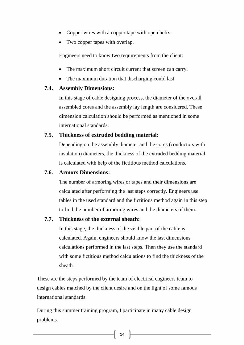
14
Copper wires with a copper tape with open helix.
Two copper tapes with overlap.
Engineers need to know two requirements from the client:
The maximum short circuit current that screen can carry.
The maximum duration that discharging could last.
7.4. Assembly Dimensions:
In this stage of cable designing process, the diameter of the overall
assembled cores and the assembly lay length are considered. These
dimension calculation should be performed as mentioned in some
international standards.
7.5. Thickness of extruded bedding material:
Depending on the assembly diameter and the cores (conductors with
insulation) diameters, the thickness of the extruded bedding material
is calculated with help of the fictitious method calculations.
7.6. Armors Dimensions:
The number of armoring wires or tapes and their dimensions are
calculated after performing the last steps correctly. Engineers use
tables in the used standard and the fictitious method again in this step
to find the number of armoring wires and the diameters of them.
7.7. Thickness of the external sheath:
In this stage, the thickness of the visible part of the cable is
calculated. Again, engineers should know the last dimensions
calculations performed in the last steps. Then they use the standard
with some fictitious method calculations to find the thickness of the
sheath.
These are the steps performed by the team of electrical engineers team to
design cables matched by the client desire and on the light of some famous
international standards.
During this summer training program, I participate in many cable design
problems.

15
VIII. CABLE DESIGN PROBLEM
In this part, one cable design problem will be discussed and solved as one
example of what I have designed during the summer training period.
The cable specifications:
4x10 mm2/ Cu / XLPE / SWA / PVC / (0.6/1 kV) (1.2 kV) – Stranded Round
Circular – IEC / [Adiabatic short-circuit current = 2kA for 1 second]
The explanation:
The cable is to be designed has the following properties:
No. of cores: 4.
Cross section area of conductor: 10 mm2.
Cross section area shape: Stranded Round Circular.
Conducting material: Copper
Insulating material: XLPE (Cross Linked Polyethylene)
Armor: Steel Wire Armor (SWA)
Sheathing material: PVC (Poly-Vinyl Chloride)
The operating voltage = 0.6 kV ph-ph/ 1 kV L-L
The maximum operating voltage = 1.2 kV L-L
The international standard: (IEC 60228) & (IEC 60502-1)
The cable screen can carry a short circuit (fault) current of 2 kA for 1 second at
adiabatic conditions (no heat transfer).

16
The designing steps:
Conductor:
From the IEC 60228 standard, the conductor should have the
following:
Resistance = 1.83 Ω/km
Resistivity (p)= 17.241
No. of wires (nw)= 7
So, we to find the wire diameter (dw):
The stranding factor (KS) = 1.2 (given)
The Assembly factor (KA) = 1.3 (given)
dw = =
= 1.635 mm + 0.2 mm (to reduce the effect of tolerance
So, the designed diameter of one wire should not be less than
1.635 mm to keep the resistance within the allowed range.
The weight of copper used = π*0.25*dw2* nw* Ks* Ka* N*dens
= π*0.25*1.8352* 7* 1.2* 1.3* 4*8.96
= 564.03 kg/km
Insulation:
From the IEC 60502-1 standard, the nominal thickness of
insulation for a 10 mm2-cross sectional area, copper conductor
should be: 0.7 mm and the minimum thickness
= 0.9 tn- 0.1 = 0.53 mm
So, the diameter of the core = 3 dw + 2 tn
= 1.835 * 3 + 2 * 0.7 = 6.9 mm
Screen:
The type that will be used in this cable is the one called "Copper
wires with a copper tape with open helix".
So, the purpose of this step is to determine the diameter of wires,
the number of wires and the thickness and the width of tape.
The given requirements are:
Adiabatic short circuit current = 2000 A

17
The duration of discharging = 1 sec
The designing steps:
1) Finding the geometrical cross section area (S) of the
combination of the tape and wires according to the equation:
Isc2 x t = K
2 x S
2 x ln ( (Өf+β)/ (Өi+β)) , where
Isc = short-circuit current = 2 kA
t = duration of discharging
K = constant depending on the material (Cu = 226)
Өf = final temperature
(According to the IEC60502-1, XLPE = 250oC)
Өi = initial temperature
(According to the IEC60502-1, XLPE = 90oC)
So, from the last equation and its known variable, we get:
S = 13.978 mm2
JCC uses copper tapes with thickness of 1 mm and width of
15 mm.
2) To calculate the diameter and the number of wires:
S = [0.25 x n x π x d2 + t x w] x N, where
n = number of screen wires.
d = diameter of screen wires.
t = thickness of the tape.
w = width of the tape.
N = number of cores.
Since we have two variables in the equation, we use an Excel
Sheet Calculation to make a trade of between the number of
wires and the diameter of one screening wire that give us the
minimum weight of the screening copper.

18
Assembly Diameter:
The assembly diameter is the diameter of the combination of the
four cores, the filling material and the tape that collect them
together.
Assembly diameter = core diameter * KIEC
= 6.9 * 2.42 = 16.7 mm
To perform the other stages of designing, engineers should
perform some external calculations called "The Calculation
Fictitious Method".
The Fictitious Calculation Method:
Dc = fictitious core diameter
Df = fictitious assembly diameter

19
Db = fictitious diameter over bedding diameter
Dx = fictitious diameter over armoring
Tb = fictitious thickness of bedding
Dc = dl + 2ti = 3.6 + 2 x 0.7 = 5 mm
Df = KIEC* Dc = 2.42 x 5 = 12.1 mm
Tb = 0.4 mm because Df < 40 mm
Db = Df + 2Tb = 12.1 + 2 x 0.4 = 12.8 mm
Dx = Db + 2Tb = 12.9 + 2 x 1.25 = 15.4 mm
Thickness of extruded bed:
Considering Df = 12.1 mm as found in the last calculation
method and using table 8 in the IEC 60502-1 standard, it is found
that: The thickness of bedding material = 1 mm.
Armor Diameter:
Using the given value of Tb and table 9 in the IEC 60502-1, it is
found that:
The armoring wire diameter = 1.25 mm
Thickness of Sheath:
The thickness of sheath = 0.035 Dx + 1
= 0.035 (15.4) + 1 = 1.5 mm
The minimum thickness = 0.8 (1.5) – 0.2 = 1 mm
To sum up,
The final cable diameter
= Ass. Dia.+ 2 x bed thick. + 2 x Armor Dia. + 2 x sheath dia.
= 16.7 + 2 x 1 + 2 x 1.25 + 2 x 1.5
= 24.2 mm

20
IX. MATERIALS USED
The different stages of manufacturing require different raw materials as
described below:
9.1. Drawing and Annealing:
Copper: High conductivity and greater flexibility after annealing.
Can be drawn to small sizes and bunches for excellent flexibility.
Aluminum: Lighter in weight and cheaper in price than copper.
9.2. Inner semi-conductor (conductor screen):
Bondable semi-conducting polyethylene, colored black.
9.3. Insulation:
There are basically three major types of insulating materials that are
used in the insulation manufacturing process in Jeddah Cables
Company. These are:
PVC (Poly-Vinyl Chloride).
XLPE (Cross Linked Polyethylene).
Vulcanized Rubber: EPR (Ethylene Propylene Rubber).
9.4. Outer semi-conductor (insulation screen):
Bondable semi-conducting polyethylene, colored black.
9.5. Screening:
Copper tape and/or wires, because they can act as the neutral for
each unique phase (shorted together for increased surface area
capacity).
9.6. Assembly:
Polypropylene fillers, Polypropylene Tape and Mylar Tape are all
non-conducting and help to fill the space without adding lots of
weight.
9.7. Bedding:
The materials used are PVC or PE (just like insulation but of lower
quality).

21
9.8. Armoring:
The minerals used are Aluminum wire or tape, or steel wire or tape.
9.9. Sheathing:
The materials used are:
PE (Polyethylene).
LDPE (Low Density Polyethylene).
HDPE (High Density Polyethylene).
LLDPE: (Linear Low Density Polyethylene).
X. WATER BLOCKING TECHNIQUES
If water or moisture is allowed to build up inside a cable, then this will have
devastating effects on the cable lifetime and its ability to perform its tasks
safely. Electrically speaking, water in its impure form conducts electricity and
as a result, the cable temperature will increase significantly when carrying
current. However, water itself does not affect the mechanical properties of the
polymer but the insulation efficiency will be dropped.
To prevent water from building up inside the cable, some materials are used:
Cellulose based materials.
Acryl amides.
Polyacrylics.
The common property of all these materials is that they swell when they come
in contact with water. Forming the swells is the mechanism for providing
blocking against water horizontally. However, we use aluminum or
polyethylene tapes to prevent water from entering the cable vertically.
22
XI. CABLE TESTING
There are basically three stages in testing:
1. Raw material testing: checking the quality of materials imported to
Jeddah Cable Company.
2. In process testing (Quality Assurance).
3. Final product testing (Quality Control).
There are three major categories of testing that take place on the cables as
specified by the International Electro technical Commission:
Routine test: carried out the entire manufactured full length of
cable and these include measurement of the electrical resistance,
voltage test and partial discharge test.
Sample test: which involve conductor examinations, check of
dimensions, and hot set test for XLPE insulation.
Type test: which check if a 10 to 15 meter length of a cable
complies with standard characteristics or not.
XII. CONCLUSION
Working for Jeddah Cables Company gave me a great experience in electrical
cables industry in Saudi Arabia. It was a nice opportunity to gain a valuable
background in cable manufacturing process and the market of such products. This
summer training period enabled me to work with a professional team of well-
qualified, multi-nationality, electrical engineers. The process of designing depends
on many electrical courses I have been taught at the university. It was clear that
working for companies as an engineer makes him responsible for taking critical
decisions. Also, the team work skills are very significant for employees who work
in projects.

23
XIII. TABLE OF MANUFACURING FIGURES
Figure 1: Unprocessed Copper
Rod
Figure 2: Drawing and Annealing
Figure 3: The Stranding Stage
Figure 4: The Insulating Stage

24
Figure 5: Screening Stage
Figure 6: Screened Core
Figure 7: The Assembly Stage
Figure 8: The Fillers Used

25
Figure 9: Cable After Bedding
Stage
Figure 10: Armoring Stage
Figure 11: Armored Cable
Figure 12: Final Cable Products
after Sheathing