Embed Size (px)
Citation preview

FINAL REPORT
The P3 Power Generation System For Advanced Missile Defense Applications
Report to the U.S. Army Space and Missile Defense Command DARPA Office
Huntsville, Alabama
Contract DASG60-02-C-0084
Prepared By The Center for Materials Research
Washington State University Pullman, Washington
November 2008
20081215180
DEFENSE TECHNICAL INFORMATION CENTER
[nforMJrfUiifor the Deft*se Conumouty
Month Day Year
DTICShas determined on L/J^LJ i./ u? {\ollj&M2l& that this Technical Document has the Distribution Statement checked below. The current distribution for this document can be found in the DTIC® Technical Report Database.
% DISTRIBUTION STATEMENT A. Approved for public release; distribution is
imited.
] © COPYRIGHTED. U.S. Government or Federal Rights License. All other rights and uses except those permitted by copyright law are reserved by the copyright owner.
0 DISTRIBUTION STATEMENT B. Distribution authorized to U.S. Government agencies only. Other requests for this document shall be referred to controlling office.
] DISTRIBUTION STATEMENT C. Distribution authorized to U.S. Government Agencies and their contractors. Other requests for this document shall be referred to controlling office.
] DISTRIBUTION STATEMENT D. Distribution authorized to the Department of Defense and U.S. DoD contractors only. Other requests shall be referred to controlling office.
1 | DISTRIBUTION STATEMENT E. Distribution authorized to DoD Components only. Other requests shall be referred to controlling office.
] DISTRIBUTION STATEMENT F. Further dissemination only as directed by controlling office or higher DoD authority.
Distribution Statement F is also used when a document does not contain a distribution statement and no distribution statement can be determined.
] DISTRIBUTION STATEMENT X. Distribution authorized to U.S. Government Agencies and private individuals or enterprises eligible to obtain export-controlled technical data in accordance with DoDD 5230.25.

TABLE OF CONTENTS
FINAL REPORT The P3 Power Generation System
For Advanced Missile Defense Applications
Executive Summary: Major Findings of the P3 Power Generation System 2
Section 1: Power Generation Development and Components
Introduction 4 Thermal Switch 5 Engine 8 Piezoelectric Diaphragm Generator 11 Integration of Components 14 Summary and Recommendations 17 References 19
Section 2: PMN-PT Single Crystal Unimorph for Energy Harvesting
Introduction 20 Single Crystal PMN-PT Harvester „„ 21 Fabrication of Unimorphs 22 Experimental Setup 23 Experimental Results 25 Discussion 28 Conclusion 29 References 30
The P3 Power Generation System: Students supported, Academic Publications, Presentations, Patents, Conferences and Awards 32
Acknowledgements 41
Appendix: Contractual Statement of Work and Funding for the P3 Power Generation System 42

FINAL REPORT The P3 Power Generation System
For Advanced Missile Defense Applications
EXECUTIVE SUMMARY
FINDINGS ON THE P3 MICROENGINE: POWER GENERATION DEVELOPMENT AND COMPONENTS
Original Concept
The P3 project was to develop and demonstrate a highly flexible, highly modular power system for advanced missile defense applications. With its flexible, modular design, the P3
power system has the potential to become the basic building block around which the Army can build power sources for a wide variety of military platforms. The P3 can provide incrased mission endurance and flexibility due to its flexible operation requirements.
The P3 power generation system can be operated to produce power from both low and high quality waste heat sources, as well as, operate as a stand alone power supply. For example, hot surfaces such as electronic cases, exhaust pipes, or vehicle surfaces are all viable candidates as heat sources. In addition, the P3 power system can use waste heat from other power producing devices. The heart of the P3 power system is a piezoelectric membrane generator in which mechanical power is converted to electrical power. The use of piezoelectric materials to produce power promises some special advantages. Some of these advantages are: high energy density, simplicity of fabrication, and amenability to batch manufacturing with resultant economies of scale.
The primary deliverable for this project is a P3 power generation prototype. The complete system will consist of a system of engines capable of producing power from waste heat.
Findings On P3 Power Generation
• Power production by a dynamic micro heat engine with integrated thermal switch has been demonstrated.
• A micro engine operated from a constant heat source of 60°C is shown to produce 350 mW and net peak power ratio is 120.
• Employing an active thermal switch to control heat rejection from the micro engine enables engine power to be increased if the engines were cascaded.
• Thermal switch power requirements can be reduced to less than 25mW for operations of 100 Hz or more.
• Engine operation up to 150 Hz has been demonstrated but loses efficiency. • Active thermal switch developed and integrated.
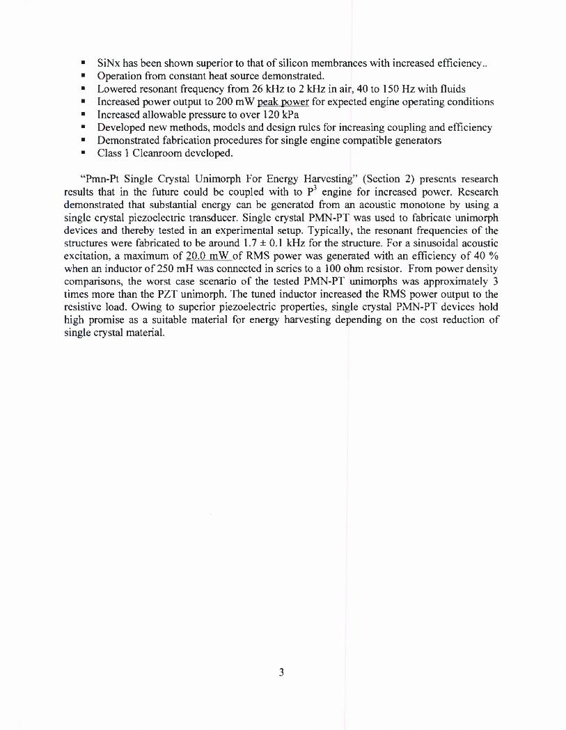
• SiNx has been shown superior to that of silicon membrances with increased efficiency.. • Operation from constant heat source demonstrated. • Lowered resonant frequency from 26 kHz to 2 kHz in air, 40 to 150 Hz with fluids • Increased power output to 200 mW peak power for expected engine operating conditions • Increased allowable pressure to over 120 kPa • Developed new methods, models and design rules for increasing coupling and efficiency • Demonstrated fabrication procedures for single engine compatible generators • Class 1 Cleanroom developed.
"Pmn-Pt Single Crystal Unimorph For Energy Harvesting" (Section 2) presents research results that in the future could be coupled with to P3 engine for increased power. Research demonstrated that substantial energy can be generated from an acoustic monotone by using a single crystal piezoelectric transducer. Single crystal PMN-PT was used to fabricate unimorph devices and thereby tested in an experimental setup. Typically, the resonant frequencies of the structures were fabricated to be around 1.7 ± 0.1 kHz for the structure. For a sinusoidal acoustic excitation, a maximum of 20.0 mW of RMS power was generated with an efficiency of 40 % when an inductor of 250 mH was connected in series to a 100 ohm resistor. From power density comparisons, the worst case scenario of the tested PMN-PT unimorphs was approximately 3 times more than the PZT unimorph. The tuned inductor increased the RMS power output to the resistive load. Owing to superior piezoelectric properties, single crystal PMN-PT devices hold high promise as a suitable material for energy harvesting depending on the cost reduction of single crystal material.

SECTION 1: POWER GENERATION DEVELOPMENT AND COMPONENTS
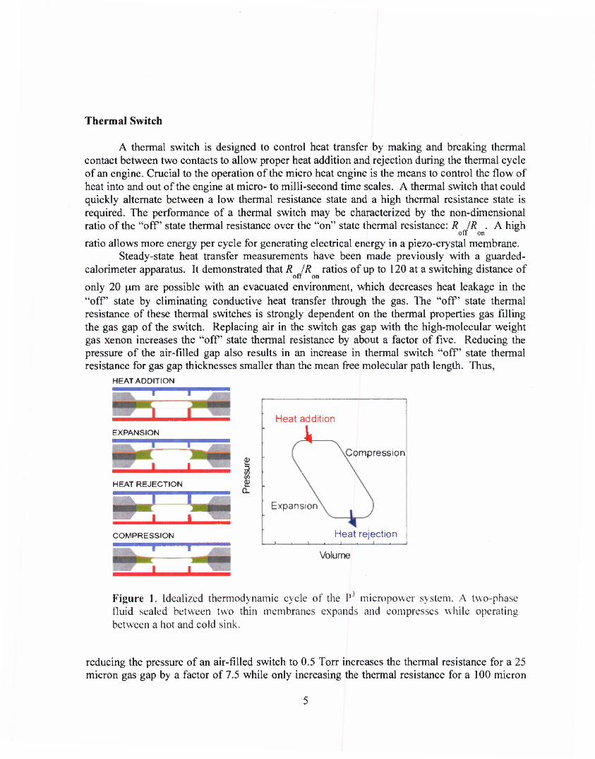
Introduction The P3 micro engine is a dynamic external combustion heat engine which utilizes a novel
thermodynamic cycle, shown in Figure 1, to convert periodic heat pulses to mechanical energy. A thermal switch controls heat into and out of the engine, which alternately evaporates and condenses a two-phase fluid. The mechanical energy from expansion and contraction of the fluid is then converted to electrical power using flexing piezoelectric membranes. The P3 micropower system has been under development at Washington State University (WSU) since 1999 with significant financial support from the DARPA MTO Micro Power Generation Program and the US Army Space and Missile Defense Command. Among proposed devices for generating power for hand-held and other portable devices, the P3 is unique in its theoretical ability to operate from waste-grade heat ranging from small temperature differences (~10 °C) to large temperature differences (100 °C) with no need for specialized fuel, no frictional or sliding surfaces, and its potential capability of large power densities, 1 W/cm3.
Ongoing research by the multidisciplinary P3 team at WSU includes thermodynamic work cycles, heat and mass transfer, micro-fluidics, dynamic mechanical behavior, microfabrication techniques and materials science for the development of piezoelectric materials in microelectronic materials. Much of the research has involved MEMS technology, and the understanding and design of individual components in the power generation system has been improving markedly over the past few years. Improved performance of individual components motivates a move towards understanding how the entire system can be integrated into an end- user power generation device.
There are three components for the P3 system. They are: 1) Thermal switch: Controls heat transfer between the engines in a cascade 2) Engine: Converts a dynamic heat source to mechanical power 3) Piezoelectric generator: Converts mechanical power to electrical power
These components can be assembled in a variety of structures, either in "sheets" to operate over a small temperature difference, or "cascades" to utilize higher temperature differences. This modularity is an inherent advantage of this system, research on individual components provides for future development of a wide range of power flexibility.
WSU achievements are highlighted in the following discussion: • Active thermal switch developed and integrated • Engine mechanical power of 1 mW produced • Engine cycle frequency of 150 Hz completed • New optimization route for piezoelectric diaphragm identified • Operation from constant heat source demonstrated • Single-engine Power
Thermal Switch
A thermal switch is designed to control heat transfer by making and breaking thermal contact between two contacts to allow proper heat addition and rejection during the thermal cycle of an engine. Crucial to the operation of the micro heat engine is the means to control the flow of heat into and out of the engine at micro- to milli-second time scales. A thermal switch that could quickly alternate between a low thermal resistance state and a high thermal resistance state is required. The performance of a thermal switch may be characterized by the non-dimensional ratio of the "off state thermal resistance over the "on" state thermal resistance: R JR . A high
off on e
ratio allows more energy per cycle for generating electrical energy in a piezo-crystal membrane. Steady-state heat transfer measurements have been made previously with a guarded-
calorimeter apparatus. It demonstrated that R IR ratios of up to 120 at a switching distance of off on
only 20 um are possible with an evacuated environment, which decreases heat leakage in the "off' state by eliminating conductive heat transfer through the gas. The "off' state thermal resistance of these thermal switches is strongly dependent on the thermal properties gas filling the gas gap of the switch. Replacing air in the switch gas gap with the high-molecular weight gas xenon increases the "off' state thermal resistance by about a factor of five. Reducing the pressure of the air-filled gap also results in an increase in thermal switch "off' state thermal resistance for gas gap thicknesses smaller than the mean free molecular path length. Thus,
HEAT ADDITION
—T r
FXPANSION
HEAT REJECTION
—! -<-• g
Q-
COMPRESSION
Heat addition
Compression
Expansion
-i . i_
Heat rejection
Volume
Figure 1. Idealized thermodynamic cycle of the P mieropower system. A two-phase fluid sealed between two thin membranes expands and compresses while operating between a hot and cold sink.
reducing the pressure of an air-filled switch to 0.5 Torr increases the thermal resistance for a 25 micron gas gap by a factor of 7.5 while only increasing the thermal resistance for a 100 micron

gas gap by a factor of 3. These results demonstrate practical thermal switches with thermal resistance ratios R IR greater than 50 are feasible.
off on °
With the results of the switch environment, the effect of conductive material at the gap has been investigated. There has been an effort to replace the mercury liquid droplets with vertically-aligned carbon nanotube turfs (VACNTs). An array of VACNTs on a silicon die is shown in Figure 2.
Figure 2. Carbon nanotube turfs arrayed on a silicon die.
Figure 3 is a comparison of the thermal resistance of the switch in the on and off positions with three gap materials - mercury, VACNT, and nothing (polished silicon surfaces). As expected, there is no significant difference between the gap materials in the off-state but VACNTs and silicon underperforms the mercury in the switch "on" state. Carbon nanotube arrays are still being pursued with a view towards decreasing the thermal resistance through surface modification of the VACNTs.

200
o *»—•*'
8 150
c TO U) 100 to (U (T SO TO F l—
0) 0
o
o c TO -^
C/) O) cr "TO E k_ <v
120
Gap Length (um)
3U " -•— Si —•— VACNT
40 - -^^•- Hg
30 - ON
20 -
10 -
n - •- -r»— =^= =!*=
00 0 2 0 4 0 6 08 1 0
Load (N) Figure 3. Steady-state thermal resistance in the on and off for three gap materials - polished silicon. VACNT (carbon nanotubes. and mercury).
For steady-state measurements and technique, the results of dynamic heat transfer measurements are added. Figure 4a is a plot of the temperature (with other switching parameters such as the force and deflection) versus time. Figure 4b is an examination of one switching event. A surprisingly high switching speed of 1600 °C/second has been accomplished corresponding to a nearly 20 °C temperature change over approximately 10 ms. The heat-transfer rate is 50 mW with the switch in the "on" state over an area of 0.04 mm2.

0 02
0 01
000
-0 01
-0 02
-0 03
-0 04
z E
•o §
Deflection Force Switch Temp. Contact Temp. Inner Radii Temp. Outter Radii Temp.
O 55 o^ ^T 50
(D
I-
40
35
30
-
0.01 s
1
Switch Temp Contact Temp
"I T I "
-1800 -1795 -1790 -1785 -1780 -1775 -1.770
Time (sec) Figure 4. Dynamic heat transfer, a) temperature, deflection and load vs. time during a thermal switching test, b) Close-up of the contact temperature - the temperature of the contact rises to the switch temperature in 0.01 s.
Engine
Progress in the understanding of the heat transfer, mechanics and thermodynamics of the r engine continues in WSU's advanced analytical laboratory. The development of a thermal switch suitable to control heat transfer to-and-from the micro heat engine is described. The use of the thermal switch is shown to enable engine cycle speeds up to 150 Hz, engine efficiencies up to 0.095% and power output up to 1.0 milliwatt of mechanical power from an engine with an externally-powered benchtop switch. The internal irreversibility (a measure of total losses due to friction-like effects) of the engine is measured to be 23%. If thermal switches can be designed to allow engines to be stacked in a cascade then the cumulative engine efficiency for the stack of engines would be increased considerably.
The internal irreversibility of the micro heat engine, or loss due to viscous dissipation, measured by "ringing out" the engine is shown in Figure 5. The decay in kinetic energy of the membrane implies losses due to viscous dissipation are 23% of the engine's mechanical power output. For comparison, the losses due to friction in a typical two-liter displacement spark- ignition engine running at 4000 rpm (67 Hz) are approximately 20% of mechanical power output [1]. The losses due to viscous dissipation in the micro-scale heat engine investigated are comparable to frictional losses in a macro-scale heat engine.
8

-0 03 10 15
Time (ms) 20
Previous work had indicated that cycle frequencies above 40 Hz were not possible for a passively cooled engine [2]. The higher heat transfer rates and the greater control over heat
Figure 5. Ring-out of an engine. The speed of decay in the signal is indicative of the viscous dissipation.
rejection provided by the thermal switch is demonstrated in Figure 6. Furthermore, optimizing both heat addition and heat rejection processes leads to greater mechanical power output and increased efficiency. Figure 7 plots membrane displacement in an engine utilizing an active heat rejection switch, operating at 100 Hz.
50 Heat Rejection without Thermal Switch Heat Rejection with Thermal Switch
10 20 30
Time (ms)
Figure 6. Plots of deflection of the engine membrane vs. time at 40 Hz for a passively-cooled (top) and actively-cooled engine (bottom). Mechanical output and mean displacement is lower when actively cooled.

10 15 Time (ms)
Figure 7.Deflection of the top membrane with the engine operated at 100 Hz.
Reducing the thermal mass and increasing the compliance of the top membrane also leads to greater mechanical power output and increased efficiency. Figure 8 shows a plot of engine efficiency (thermal to mechanical conversion) versus heat input per cycle for an engine with a 300 nm thick silicon nitride top membrane running at 40 Hz and 100 Hz. As before, faster cycle speeds lead to higher engine efficiencies that peak at an optimum heat input per cycle. In this case, the more compliant and less massive silicon nitride top membrane results in a maximum thermal-to-mechanical efficiency of 0.095% at a heat input of 10.7 mJ per cycle during 100 Hz operation. Under these conditions the micro engine produces 1.02 milliwatts of mechanical power.
0 10
~ 0 08 o c 0 G 006 £ LU
S 004 c 3 1 0 02
000
SiNx 40Hz (%) SiNx 100Hz (%)
2 4 6 8 10 12 14
Input Energy (mJ)
Figure 8. Thermal-to-mechanical efficiency at 40Hz and 100 Hz as a function of thermal energy input. A maximum is seen in the 100 Hz data, corresponding to the onset of capillary wick "dry-out".

Engine efficiencies peak at an optimum heat input per cycle. This optimum heat input corresponds to "dry-out," or to the energy required to vaporize all liquid working fluid in the wick. The optimum heat input shifts down to lower values as cycle speed increases because of the finite pumping speed of the wicking structure.
The effect of wicking structure geometry on engine output can be seen in Figure 9. In the figure top membrane displacements for engines with silicon nitride membranes and two different capillary wicking structures are shown. As previous experience has shown, design of the capillary wick has enormous effects on both the maximum speed and efficiency of the engine. Computational modeling to identify improved wick designs continues.
70 Radially Increasing Wdth Channel Constant Width Channel
Figure 9 Membrane displacement vs. time for two different capillary wick designs. Capillaries that increase width radially from the center can produce nearly 50% more displacement from the engine by more efficiently vaporizing the liquid.
Piezoelectric Diaphragm Generator
Typical operating pressures for the engine are 5-25 kPag (roughly 1-5 psi). To optimize the design of the piezoelectric generator, the most appropriate mechanical treatment for the piezoelectric diaphragm in the P engine - either as a plate, or a membrane - must be decided. This means a plate bends just like beams in classical structural mechanics problems. A membrane (the mechanical construct) only stretches like a rubber band. According to recent models [3] that distinguish between the two mechanical extremes, the diaphragm may be treated as a membrane due to its thinness and the large pressures exerted on it. In fact, pressures above 0.1 kPa are sufficient that bending effects may be ignored.
The electromechanical coupling of a device, A^2, is defined as the fraction of electrical energy transduced when the transducer is acted upon mechanically (the so-called "receive" mode). Electromechanical coupling directly impacts the amount of electrical power produced.
A new model and test for the electromechanical coupling of the diaphragm generator to pressure has been developed [4]. This is in direct contrast to the previous electromechanical
11

3.
coupling tests (the so-called "impedance" test), where there was no differential pressure over the diaphragm. Central to this model are the quantities:
1. characteristic membrane strain echar = w2/a2, center-point deflection divided by the
sidelength of the diaphragm, squared; 2. the normalized thickness fraction in the diaphragm of the piezoelectric material,
TP =tp/t;
the elastic modulus ratio, Et>/E$, of the piezoelectric material to the substrate material; and, the transverse electromechanical coupling for an elastically isotropic piezoelectric material: k2
x = e2Je-iiE?.
is the upper bound for k1 of any piezoelectric transducer operating in the transverse mode.
The results from two piezoelectric diaphragms are shown in Figure 10. Both diaphragms are 5 mm x 5 mm square. The "high-stress" diaphragm has an effective residual stress of 120 MPa and the "low-stress" diaphragm has an effective residual stress of about 40 MPa.
Figure 10 displays plots of pressure (left axis) and k2 (right axis, calculated as described above) vs. characteristic strain. The ultimate coupling for the high- and low-stress diaphragms is 0.6% and 2.0%, respectively. The high-stress diaphragm approaches the limiting coupling at much higher strains than the low-stress diaphragm. Also, the lower limiting coupling is a consequence of the relative thicknesses of PZT to support material (the low -stress diaphragm has 3 um of PZT as compared to 1 u.m of PZT for the high-stress diaphragm). These coupling coefficients are much larger than reported from the (zero-pressure) impedance tests - these were on the order of 0.0040% to 0.12% at best.
Kj,
T-T T T TTT] f rTTTm
100 - Pressure
/
-k2 - high-stress
P (k
Pa)
o
- k2 - low-stress - Fit of k2 /^____:
/
Pre
ssur
e.
< •
(a)
: 001
1E-3 0.01 0.1 1 10 100 1000 0.01 0 1 1 10 100 1000
Characteristic membrane strain, w^/a2 x 106 Characteristic membrane strain, \VVa2 x 106
Figure 10 Pressure and k2 vs characteristic strain for the a) high-stress and b) low-stress diaphragms. The limiting coupling is 0.6% for the high-stress and 2.0% for the low-stress diaphragm.
12

Figure 11 is a plot of the electromechanical coupling of the diaphragm in the large strain limit for several ratios of Ep/Es as a function of Tp. Also plotted in Figure 11 are the limiting normalized A^s extracted from the fits shown in Figure 10 for the high- and low-stress diaphragms (with k]x a 6% for the sol-gel PZT film that we use). Ep/Es for each diaphragm is
also listed on the plot. The coupling approaches a limiting value as the mean deflection of the diaphragm becomes large.
1.0
en c "5.
l| si TO OJ
£0.8
- 8 0.6
ID 0.4
"8 0.2
1— 1— ' t 1 1 ' '_—-l-—-^^ya
\^^^\ jS / / I -
/ 4 /
/ / 2 > / /
I / / 1 0.5 /
i 1 / / /A 0.25
"/// / ;/ /* ̂ "0 50
y/C^^^042 lkZ^r i.i. I.I, r- 0.0
0.0 0.2 0.4 0.6 0.8 1.0 Thickness fraction of piezoelectric, rp
Figure 11 Normalized high-strain limiting coupling vs. tp for different values of Ep/Es. The values derived from experiment for the high-stress (blue) and low-stress (red) diaphragms are plotted with their corresponding rp for comparison.
This latest work on the piezoelectric diaphragm represents a significant change in design principles, in test methods, and ultimately in philosophy. The limiting electromechanical coupling of the diaphragm may be as large as that of the transverse coupling of the piezoelectric material which is much larger than the electromechanical coupling coefficients found from a zero-pressure bending test (the impedance test). In practice, this can be approached by increasing the relative sheet-stiffness of the piezoelectric relative to other lamina (such as electrodes and support layers). In this design method, similar to the design model previously developed for a bending-mode piezoelectric transducer, lowering the tensile residual stresses in the structure are beneficial. The sheet stiffness of the support structure should be reduced as much as practically possible. Diaphragm modifications that attempt to realize different boundary conditions will only be useful over a very small fraction of the diaphragm and, in practice, will not be useful.
One avenue that may be useful for future prototyping is the use of polymer piezoelectric - polyvinlydene fluoride, PVDF or single crystal thin films which have been made at WSU to 195 microns. PVDF can be purchased in large sheets that already have electrodes and they have a
13

transverse coupling coefficient of approximately 1.5% (as reported by the manufacturer). PVDF is also quite gas-impermeable for a polymer due to its semi-crystalline nature and should be able to contain the working fluid for reasonable amounts of time (although how long is currently unknown). PVDF limits the temperature of operation of the engine due to the low Curie temperature of 80°C. However, the physics do not change and polymer-PZT composite materials (which currently exist or are in late stages of commercial development) would be a direct drop-in for PVDF. This would be a complementary path to exclusive silicon-micromachining technology which is a time-consuming endeavor in a research environment that can detract from many unknown best-operating principles for this type of engine-generator system.
Integration of components
Power production by a dynamic micro heat engine with integrated thermal switch has been achieved. A passively cooled micro engine operated from a constant heat source of 60°C is shown to produce -354 uW mechanical power. Employing an active thermal switch to control heat rejection from the micro engine enables engine mechanical power to be increased to ~1100 uW. Power consumption by the thermal switch is shown to be minimized by operating the cantilever switch at its resonant frequency. Thermal switch power requirements can be reduced to less than 4 >AW even for operations speeds of 100 Hz or more.
Work on the thermal switch has been directed at the realization of a switch design in which an array of liquid-metal micro-droplets deposited on one silicon substrate makes and breaks contact with a second silicon substrate. A schematic and photograph of the completed prototype is in Figure 12. The thermal switch controlling heat transfer to/from the micro engine took the form of a liquid-metal micro-droplet array (1600 thirty-micron droplets) deposited on a silicon die. The micro-droplet-array die was glued on the tip of a piezoelectric cantilever actuator. The cantilever thermal switch was then mounted immediately below the engine so that as the cantilever flexed the micro-droplet array would make contact with the bottom evaporator membrane.
Switch Off
Vrdiiirm C I lirrmal Switch Hwtf Source
Switch On
Figure 12. Left: photograph of the integrated engine + switch. Right: schematic of the operation of the engine with the thermal switch off and on.
14

To run the engine, the cantilever thermal switch was heated to a constant temperature of 60 to 65°C. Heat transfer to the engine was then controlled by actuating the cantilever thermal switch to periodically make and break contact with the bottom evaporator membrane. The operation of the micro heat engine with heat addition from a constant temperature heat source at 60°C is illustrated in Figure 13. In these experiments, heat rejection from the engine was by passive cooling to the surroundings at 20 °C. The primary reason for the decline in engine output is the rise in average engine temperature as engine cycle speed and thermal power into the engine increases.
Time (sec)
Figure 13 Plots of deflection of the engine membrane vs. time for the integrated engine operated from a constant-temperature heat source at (from top to bottom): 1Hz, 2 Hz. 16 Hz.
15

Figure 14 shows power output versus energy in per cycle for a micro engine that is actively cooled by a thermal switch and heated by electrical resistance. Power data for cycle speeds of 20 and 40 Hz are plotted. The use of the thermal switch to actively control heat rejection from the engine is seen to dramatically increase the power output of the micro engine. Maximum power out of the micro engine increases to -600 u. W of mechanical power at a cycle speed of 20 Hz and to ~1100 u.W mechanical power at 40 Hz.
0)
o Q_
1200
1000 • 20Hz vv
800 V 40 Hz
v v
600 • v
400 • • V
200 V •
0 i %-0 *V . . . 1
0 10 20 30 40 50 60
Energy In Per Cycle (mJ)
Figure 14. Mechanical power output versus energy in per cycle for a micro engine actively cooled by a thermal switch at 20 and 40 Hz. This engine was run from an electrical stimulant for heat addition.
A concern is the increasing power required to operate the thermal switch at higher cycle speeds which may be addressed by running the cantilever thermal switch at its resonant frequency. Figure 15 shows the power required to deflect three cantilever thermal switches 40 microns versus operating frequency. Thermal switch power is seen to reach minima for the respective resonant frequencies of -73, ~173 and -235 Hz. Thermal switch power requirements can be reduced to less than 4 JAW electrical, even for operations speeds of 100 Hz or more.
16

1000.0
Q.
5 o Q.
100.0 -
10.0 -
1.0 -
0.1
•*— 64 x 20 x 0.6 mm -*— 8 x 40 x 0.6 mm
• 5 x 38 x 0.6 mm
T
100 200 300 Frequency (Hz)
400
Figure 15. Electrical power consumed by the active thermal switch vs. frequency for three different cantilever geometries. The frequency at which minimum power is consumed corresponds to resonance of the cantilever.
Summary and Recommendations
This report details the P3 power generation project at WSU and the current state of the major constituents: the thermal switch, the engine, and the piezoelectric diaphragm. Careful heat transfer measurements and technique have shown that the thermal switch, with a liquid-mercury intermediate, is capable of achieving thermal-resistance ratios of 120 over a switching distance of only 0.02 mm. This performance is much better than needed for the engine. However, these measurements are in a relatively exotic environment - vacuum or heavy noble gas. It will take more development to move these thermal switching techniques off of the laboratory bench.
A benchtop thermal-to-mechanical engine with a macro-scale thermal switch has achieved an individual mechanical power output of 1 mW and speeds up to 150 Hz. Continued capillary wicking evaporator improvement and better bench-top thermal switching designs have resulted in greater efficiency and speed. Further increases in speed are limited by heat transfer through the engine. Achieving a resonant condition in the engine, and therefore thermodynamic gains due to hysteretic pressure-volume behavior, is still believed to have the greatest potential for power output gains. Additional work will be required to optimize fluid flow conditions in the wicking structures which have been developed to be an integral part of the engine assembly.
By starting from what was known about piezoelectric diaphragms, the optimization problem has been a continuation of the mechanics of a vibrating piezoelectric plate. However, for the operating conditions for the P3 engine the resulting improvements in plate like conditions did not scale during operating conditions, suggesting another model for piezoelectric behavior of the structure was required. A new technique and theory of how the piezoelectric diaphragm couples to large differential pressures has shown that the electromechanical coupling is greater
17

than previously thought. The result has been a demonstration of coupling coefficients of up to 2%, over 10 times higher than previously demonstrated for k1. The favorable resonant conditions (in vacuum, etc.) that resulted in high theoretical energy transduction are not possible in the engine. Furthermore, because of the way that mechanical energy was measured (by considering the actuator work that was exchanged through the compliant membrane), electrical work must be considered to be a fraction of that work, with no additional multipliers for resonance possible . Transverse electromechanical coupling coefficients are on the order of 20% for the best piezoelectric materials, and closer to 6% for the PZT that we currently use. Therefore, it is likely that approximately 5-10% of the mechanical power generated by the engine is what is practically recoverable as electrical power through the piezoelectric diaphragm structure.
One of the advantages of the P3 is the enormous reduction of mechanical complexity from traditional dynamic heat engines. However, this has constricted the operating conditions of the engine: the speed is constricted such that the engine must be running at the resonance speed. This is an extremely constrained operating point with little room for flexibility in the quality and temperature of the heat source. This is an area for potential great gains. Energy recovery to this point has been the simplest arrangement possible: electrical dissipation over a resistor. There has been much work in the energy-harvesting literature detailing electrical schemes for both mechanically-controlling the piezoelectric and for increasing the recovered energy by a factor of 8 (as compared to simple resistor dissipation), see Reference 1 for an example. The electrical energy increases are obvious; but this also shows a path for increasing the mechanical output by manipulating the diaphragm at the correct times, analogous to opening and closing valves at specific times in a combustion engine cycle. The reduction in mechanical complexity in the P3
has been at a significant cost: the lost mechanical function may need to be replaced by electrical function to have a flexible, efficient engine. This has been possible on benchtop demonstrations, but will require further work to create final packaged devices which achieve similar performance. Through the piezoelectric effect, it is of course possible to add this timing type behavior and reproduce the performance on the benchtop with additional work on the electrical controls system.
Other successes of the P3 project are the spin-off applications. These include: 1. The identification of a tremendous amplification affect on the acoustic output of a
piezoelectric diaphragm when pressure is applied to one side. With our current piezoelectric diaphragms, it appears that the sensitivity is greater, the size is smaller, and the power consumption is potentially much lower than current coil/magnet speakers for small-scale use (such as cellular telephones). Extension of this technology may also have applications in open-field and medical acoustic imaging arrays. This technology is being submitted to the WSU Research foundation for intellectual property disclosure (D.J. Morris, M.J. Anderson, D.F. Bahr)
2. Investigation of the non-linear mechanics of the piezoelectric diaphragm for the P3 has also inspired another new technology on a related project, which was a subcontract of a Navy STTR to develop vibration-energy harvesting technology for DDX destroyer health monitoring. One of the stumbling blocks for the vibration-harvesting community has been the problem of coupling to the ambient frequencies by a mechanical resonator with a fixed resonant frequency. A frequency-tunable mechanism for vibration harvesting has been designed that has over double the tuning range of other known designs, with the additional advantage of being compact. This technology has been tested and submitted to the WSU Research foundation for patent disclosure (D.J. Morris, D.F. Bahr).
18

3. Furthermore, the thermal switching science and technique has also found a unique niche. The high thermal switching speeds discovered, as well as the technology to make the switch very effective with as small as 20 u.m standoff distances makes this a very pursuable technology to control temperatures in microelectronics, as well as timed-cooling technology for polymerase chain-reaction (PCR) DNA amplification reactors.
References Cited
1. A. Badel, D. Guyomar, E. Lefeuvre, and C. Richard, "Efficiency Enhancement of a Piezoelectric Energy Harvesting Device in Pulsed Operation by Synchronous Charge Inversion", Journal of Intelligent Material Systems and Structures, Vol. 16, No. 10, 889- 901 (2005)
2. J.B. Heywood, Internal Combustion Engine Fundamentals, First Edition, McGraw-Hill, New York, 1988.
3. S.A. Whalen, D.F. Bahr, CD. Richards, and R.F.Richards, "Characterization of a Liquid- Vapor Phase-Change Actuator," Proc. of ASME IMECE, Florida, U.S.A., Nov. 5-11, 2005, Paper No. IMECE-82564.
4. U. Komargiri, M.R. Begley, and J.G. Simmonds, J. App. Mech. 72, 203-212 (2005). 5. D.J. Morris, M.C. Robinson, L.W. Weiss, CD. Richards, R.F. Richards, D.F. Bahr,
"Mechanical-to-electrical Energy Conversion of Thin-film Piezoelectric Diaphragms", Mat. Res. Soc. Symp. Proc, 973, paper # 0973-BB06-04, Boston, MA, November 2006.
19

Section 2: PMN-PT Single Crystal Unimorph for Energy Harvesting
Introduction
Energy harvesting devices using piezoelectric materials has been a promising area of interest in recent past. The power generation capability of these devices for ensuring a steady and reliable source of energy has gained significance. These smart structures can be used for harvesting energy from ambient sources for running low power battery-less devices typically of the order of 10 - 100 mW. A majority of the designs are based on the application for providing sufficient usable power to the on-board electronics.
Kymisis et al. demonstrated they can harvest energy lost during walking using a combination of Polyvinylidene Fluoride (PVDF) laminate structure and a Thunder actuator, a pre-stressed Lead Zirconate Titanate (PZT) composite, in a shoe [1]. The average power generated was 1 mW with the PVDF stave and 2 mW with the Thunder for the inserts in the shoe. Umeda et al. used a steel ball impacting against a thick PZT film to produce power and store it in a capacitor [2]. Sodano et al. demonstrated power harvesting by a PZT cantilever beam attached to an automobile compressor [3, 4]. A 60 mm x 63 mm PZT bonded to aluminum plate charged a 40 mA-h battery in an hour. Roundy, et al., also studied low level vibrations and realized about 70 uW/cc power density using a PZT cantilever structure [5-7]. Several other researchers used the PZT based cantilever structure to harvest energy from random and periodic vibrating sources [9]. Circular unimorph structures have been also used in order to harvest energy in a transverse mode of excitation. Ericka et al. used a PZT on brass unimorph and generated 1.8 mW with 2g acceleration from a periodic shaker [10]. Kashyap et al. fabricated an acoustic energy harvester of a PZT unimorph coupled to the back-plate of a Helmholtz resonator [11].
All of the methods discussed above used mostly PZT as the piezoelectric material bonded to either brass or stainless steel substrate to form the cantilever structure. Moon et al. for the first time used a cantilever beam with Lead Magnesium Niobate - Lead Titanate (PMN-PT) single crystal for energy harvesting [12]. Their prototype PMN-PT single crystal energy harvester 10 mm x 1.2 mm produced about 65 uW from a displacement of 50 urn at 190 Hz. Ren et al. prepared a multilayer PMN-PT single crystal and epoxy composite and a volume fraction close to 50 % of PMN-PT generated 96 mW/cc with 88 MPa of axial stress [13]. This review indicates researchers are still investigating how to use the excellent piezoelectric properties of PMN-PT in applications for energy harvesting. Recent theoretical work by Clark et al. provided a fair comparison of the performance of PZT and PMN-PT unimorphs [14]. The PMN-PT unimorph under optimal design harvested more than 10 times the power than a PZT unimorph under same applied stress. In this article, PMN-PT single crystal piezoelectric material was used for energy harvesting from mechanical vibrations arising in the back-plate of an acoustic resonator. The resonator had a piezoelectric element bonded to a brass back-plate structure. Previously, the source of excitation and the choice of piezoelectric material have varied widely depending on the nature of application and performance of the material.
For a specific application, the overall efficiency of energy harvesting depends on two broad parameters: 1) the transducer efficiency; and 2) the power conversion efficiency. The transducer efficiency depends on the type of piezoelectric material and its coupling to the medium from which energy is harnessed. The power conversion efficiency depends on the
20

circuitry involved for supplying power to the electrets load. Using passive electronic components will help to increase the power conversion efficiency. The output impedance of the electrical load circuit can be tuned to match that of the piezoelectric device for maximum power transfer.
Single Crystal PMN-PT Harvester
The Center for Materials Research (CMR) focused on using single crystals grown from starting composition PMN-0.5 PT for an acoustic energy harvesting application. PMN-PT is a relaxor ferroelectric with the composition formula of (1-x) Pb(Mgi/3Nb2^)03-x PbTiC»3, (where 0.28 < x < 0.38) after growth. PMN-xPT single crystal is stable at room temperature and exhibits excellent piezoelectric properties near the morphotropic phase boundary (MPB) [15]. At room temperature, the degree of polarization depends on the composition of crystals and direction of poling.
The power harvested by a piezoelectric material due to an applied stress is directly proportional to the square of the piezoelectric charge coefficient (d). Hence, it is an important metric of a material's performance upon excitation. The two most common modes of operation are in the longitudinal, da, and the transverse mode, d^. Clark and Ramsay [16] have investigated both modes da and dn for a PZT sample. They concluded that the dsi mode had a mechanical advantage over da in coupling with a low excitation medium and harnesses more electrical power. Moreover, the longitudinal mode has a resonance at higher frequencies suitable for use in ultrasonic bandwidth.
Monochromatic sound sources over 120 dB have significant power densities as compared to vibration sources, Table 1. The pressure due to an acoustic field decreases with distance from the source and the sound power is taken as the average over a finite area of the sound field at any location. Symko et al. demonstrated heat energy can be converted to sound energy using thermo- acoustic engines and generate high sound pressure level (SPL) of more than 135 dB at a resonant frequency [20, 21]. The sound from the thermo-acoustic engine when coupled with the unimorph would operate at the transverse resonant mode of the device. Figure 1 shows the schematic of a unimorph structure where the direction of electrical polarization, E, is parallel to the sound pressure, P.
Table-1: Comparison of power density of acoustic source used for energy harvesting
Energy source Power density Comments Reference
Vibrations 0.116mW/cmJ Microwave oven Raghunathan et al. [8]
Vibrations 0.2 mW/cm3 Steel head (8m/s2 at 50 Hz) Roundy et al. [6]
Acoustic Noise 0.00096 mW/cmJ Low freq. noise at 100 dB Roundy et al. [7]
Acoustic
Monochromatic
(plane-wave
tube)
200 mW/cm2 147 dB, 1 kHz and 100 cm
from source From theory.
0.2 mW/cm2 117dB, 1 kHz and 100 cm
from source
21

F//P t
Piezoelectric element
Without E field - No Stress on the elements
With E field - Constrained on the edges.
Figure 1: Piezoelectric - non-piezoelectric Unimorph Structures. Here the applied electric polarization, E, is parallel to sound pressure, P.
Fabrication of Unimorphs
(1-x) PMN- x PT single crystal boules were grown in the CMR laboratory with starting x = 0.30, using the self-seeding high pressure Bridgman (HPB) technique [17]. The ingots were grown in semi-round 99.99% pure platinum crucibles. Final diameters of recent ingots were 89.0 - 120.0 mm in diameter, thicknesses ranging from 19.0 - 38.0 mm, and weighing up to 1.9 kg. Figure 2a shows a 114 mm diameter PMN-PT ingot as grown in the furnace. The single crystals were sliced into 0.19 ± 0.01 mm thick wafers perpendicular to the flat top surface using a multi- wire saw as shown in figure 2b. Figure 2c shows a wafer of PMN-PT after it was sliced. The chosen slicing direction yielded larger sized samples for fabrication of unimorphs and less composition variation across a single wafer.
The transverse mode piezoelectric coefficient du for crystals with composition near MPB is higher in <110> poled samples than in <100> poled samples. Table2 below shows a comparison of CI31 coefficient and dielectric constant for PMN-PT and PZT-5H ceramic for major poling directions [18]. Circular discs were cored from the sliced PMN-PT wafers. A fine layer of gold (200 - 300 nm) contact was deposited on the PMN-PT discs. The samples were polled in a poling bath at room temperature with an electric field of 250-300 V/mm. Circular brass shims of varying thicknesses were used as the non-piezo layer for unimorphs. The PMN-PT disc was epoxied to the brass shim using a thin layer of silver epoxy from EPO-TEK. Figure 2d shows a PMN-PT unimorph mounted on a brass mount.
Table 2: Comparison of du - piezoelectric charge constants of PMN-PT and PZT
<100> Poled <110> poled <111> poled PZT-5H
du coefficient, PMN -0.31PT, [18]
-800 to-1000 pC/N
-1200 to-1800 pC/N
<-150pC/N - 274 pC/N
Dielectric Constant, PMN-0.3 PT, [19]
4500 - 6500 4000 - 6500 3500 -6000 3000 - 3500
22

Growth Direction
Slicing Top - 0.38 PT
SHL Bottom - 0.28 PT
Figure 2a: PMN-PT ingot as grown
Figure 2b: Schematic of PMN-PT ingot showing growth direction and slicing of wafers.
4
70.0 mm
PMN-PT
Brass
Figure 2c: Single crystal wafer of PMN- PT direction out of plane
Figure 2d: PMN-PT unimorph on brass back plate
Experimental Setup
A speaker from JBL (model no. 2426H) was used for simulating the sound source for the acoustic excitation. The speaker had a stable linear performance above 1000 Hz with a cross over at 800 Hz and was driven by a sine wave input from a function generator. Experiments were performed in the audible frequency range (1.0-3.0 kHz) to determine the resonant frequency of the structure with a paper cone and then the maximum power output at resonance was investigated. The unimorph was attached to a paper cone by a double sided adhesive copper tape and then placed over the speaker. The schematic in Figure 3 shows the setup and the dimensions in greater detail (not to scale).
23

=1U mm
PMN-PT unimorph
Paper cone
=ZU mm
Speaker
Figure 3: Schematic of the energy harvesting setup, (a = diameter of unimorph; b = inner diameter of paper cone; c = outer diameter of paper cone; d = depth of paper cone and e = depth of the speaker cone from voice coil).
The maximum power transfer to the load resistance was at the resonant frequency of the coupled structure. An inductor LI was added in series to the load resistance Rl to tune the circuit. This increased the output power to the load resistor. The inductor couples with the piezo element to form an electrical LC tuned circuit and hence there is an increase in RMS power. The schematic in Figure 4 shows the typical passive circuit used for RMS power. LI is also referred later as the tuning inductance and its value is dependent on the resonant frequency, the dielectric constant of the sample and thickness of the unimorphs. A 10 Q shunt resistance, R2, was used to determine the current through the output circuit.
L ^
PMN- g^imorp h
V?77fi7?7}}7}%^ I
t P // <110>
T
200-500 mH
R
R
t 100 $2
10 £2
Figure 4: Schematic circuit diagram shows the tuning inductor and Rout.
24

Experimental Results
The specification of the unimorphs fabricated is listed in Table 3. The thickness of PMN- PT disc was 0.19 ± 0.01 mm while the thickness of substrate or brass shim varied for different cases. The thickness ratio is the thickness of brass to the thickness of piezoelectric element. A more compliant non-metallic graphite substrate formed by bonding 2 single ply graphite sheets in a cross-ply manner was also tried. The input power to the speaker was calculated by using a shunt resistance.
Table 3: Parameters of the unimorph samples
Sample Name
Substrate Thickness of Substrate
(mm)
Thickness Ratio
Diameter of Substrate
(mm)
Diameter of Piezo disc
(mm) Uni-14B Brass 0.15 0.79 38.1 25.4 Uni-14C Uni-14D
Brass 0.10 0.53 38.1 25.4
Uni-14E Uni-14F
Brass 0.25 1.31 38.1 25.4
Uni-14G Uni-14H
Brass 0.30 1.58 38.1 25.4
Uni-141 Uni-14J
Graphite 0.40 2.1 38.1 25.4
PZT Brass 0.25 -0.5 27.0 20.0
The resonant frequency of the structure was determined by a frequency sweep to a 1 MQ resistance as shown in Figure 5. Multiple peaks in the frequency sweep indicated the presence of harmonics in the resonating structure. The RMS output power was measured at the resonant frequency to a load resistance Rl of 100 ohms and a tuning inductor LI in a range 200 mH - 500 mH, as shown in Figure 4. Maximum RMS power from a unimorph was obtained at a certain impedance matched condition by changing the tuning inductor to an optimum value. The input excitation voltage from the function generator was kept constant for all the tests for the acoustic excitation to the unimorphs.
25

3k 4k 5k
Frequency (Hz)
A
Figure 5: Frequency sweep for a unimorph with acoustic excitation showing resonances.
The mean resonance frequency for the set of unimorphs was 1.689 kHz with a standard deviation of 72 Hz. The output power, Poul, from the unimorph was calculated by measuring the current through the shunt. The input electrical power, Pj„, to the speaker was calculated similarly at the resonant frequency using another shunt resistance connected in series with the speaker.
Instantaneous power, p0(t) = v0(t).i0(t) 1 T
Pm=-[p0(t)xit * o
where, v0 and i0 are the output voltage and current from the unimorph
(1)
The efficiency stated in the article is the ratio of the output power from the piezo over the input power to the speaker at the operating frequency.
Efficiency (%), 17 —^-.100 (2)
Figure 6 shows the RMS power output and the efficiency ratios for the above listed unimorphs while Figure 7 shows the inductor L in mH used for tuning at resonance. With same excitation at resonant frequency, the PMN-PT unimorphs performed better than the PZT counterpart. It was seen that on an average the PMN-PT unimorphs produced more output power than the PZT counterpart. For the best case, Uni-14B produced 20.45 mW and 40.8 % efficiency at resonant frequency of 1.71 kHz. A typical PZT unimorph (available commercially) produced
26

0.89 mW and was 2 % efficiency at resonant frequency 1.7 kHz. The output power of each unimorphs was within 5% of the stated value in Figure 5 for several repeat runs.
0.020- —\
to I
D-
0.015-
0.010-
o o.oos
o.ooo
• Output Power, PJ)N) ^^Effi riency Ratio (%I
9
I
I
5555555^5'
Figure 6: Efficiency and Power output from the unimorphs
• Inductor (mH)
600- •
• •
500- • i
400-
• 300-
2D0-
• i i •
i • • i • •
• •
100-
0- —•— —'— —•— i—•— ' - i —•— • - ' —'—
5 cs555c53fc
Figure 7: Tuning inductor values in mH for each unimorph for maximum power output
27
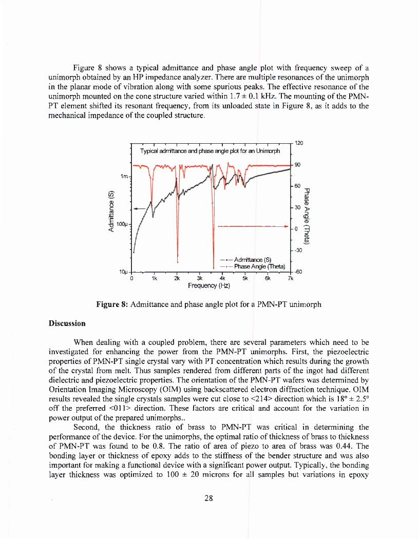
Figure 8 shows a typical admittance and phase angle plot with frequency sweep of a unimorph obtained by an HP impedance analyzer. There are multiple resonances of the unimorph in the planar mode of vibration along with some spurious peaks. The effective resonance of the unimorph mounted on the cone structure varied within 1.7 ± 0.1 kHz. The mounting of the PMN- PT element shifted its resonant frequency, from its unloaded state in Figure 8, as it adds to the mechanical impedance of the coupled structure.
1m-
CO
•I 100M <
10M
I I I I I I I I I I I I I
Typical admittance and phase angle plot for an Unimorph
-90
- Admittance (S) Phase Angle (Theta)
120
-60
30 >
<i m
S
--30
—i •, • | •| •,• | •—
1k 2k 3k 4k 5k 6k 7k -60
Frequency (Hz)
Figure 8: Admittance and phase angle plot for a PMN-PT unimorph
Discussion
When dealing with a coupled problem, there are several parameters which need to be investigated for enhancing the power from the PMN-PT unimorphs. First, the piezoelectric properties of PMN-PT single crystal vary with PT concentration which results during the growth of the crystal from melt. Thus samples rendered from different parts of the ingot had different dielectric and piezoelectric properties. The orientation of the PMN-PT wafers was determined by Orientation Imaging Microscopy (OIM) using backscattered electron diffraction technique. OIM results revealed the single crystals samples were cut close to <214> direction which is 18° ± 2.5° off the preferred <011> direction. These factors are critical and account for the variation in power output of the prepared unimorphs..
Second, the thickness ratio of brass to PMN-PT was critical in determining the performance of the device. For the unimorphs, the optimal ratio of thickness of brass to thickness of PMN-PT was found to be 0.8. The ratio of area of piezo to area of brass was 0.44. The bonding layer or thickness of epoxy adds to the stiffness of the bender structure and was also important for making a functional device with a significant power output. Typically, the bonding layer thickness was optimized to 100 ± 20 microns for all samples but variations in epoxy
28

thickness and gluing can also add a smaller degree of variation in performance due to the alteration of the effective stiffness.
For measuring power output from the unimorphs, all passive circuit components were used. Optimizing the inductor L in series with the output resistance R was critical for optimal power transfer to the load by reducing the output impedance of the device considerably. It was observed that unimorphs which required higher value of tuning inductance at resonance had inferior performance. The efficiency presented in this article is the overall efficiency of the system while correcting for the speaker performance at the operating frequency. As the PZT unimorph had slightly variant dimensions, the power density (W/cm3) for the tested unimorphs would be a better metric for comparison and is shown in Table 4.
Table 4: Power density of the tested unimorphs
Unimorph No.
Volume (cm3)
Power output (10"3 W)
Power Density (W/cm3)
U-14B
0.0962
(Dia. - 2.54 cm thickness = 0.019 cm)
20.45 0.212 U-14C 10.46 0.108 U-14D 11.83 0.122 U-14E 10.32 0.107 U-14F 6.36 0.066 U-14G 8.25 0.085 U-14H 16.22 0.168 U-14I 5.86 0.061 U-14J 14.72 0.153
PZT-Uni 0.0392
(Dia. = 2.0 cm thickness = 0.0125 cm)
0.8702 0.022
Conclusions
The need of harvesting energy for low power electronics has grown in recent past. CMR has demonstrated that substantial energy can be generated from an acoustic monotone by using a high Q tuned single crystal piezoelectric transducer. Single crystal PMN-PT was used to fabricate unimorph devices and thereby tested in an experimental setup. Typically, the resonant frequencies of the structures were observed to be around 1.7 ± 0.1 kHz for the structure. For a sinusoidal acoustic excitation, a maximum of 20.0 mW of RMS power was generated with an efficiency of 40 % when an inductor of 250 mH was connected in series to a 100 ohm resistor. From power density comparisons, the worst case scenario of the tested PMN-PT unimorphs was approximately 3 times more than the PZT unimorph. The maximum power density achieved was 0.212 W/cm3 for PMN-PT, which is a significant improvement. The tuned inductor increased the RMS power output to the resistive load. Owing to superior piezoelectric properties, single crystal PMN-PT devices hold high promise as a suitable material for energy harvesting.
Acknowledgements: The authors acknowledge II-VI Inc. and Piezo Partners for the equipment and process in HPB growth. Acknowledgement is made for the following grants: TAPEC (Grant
29

No. BAA W9113M-05-0009) and SMDC for P3 Power generation (Grant No. DASG60020084). The authors also acknowledge Dr. Orest Symko for his insights and Dan Clingman for the Graphite substrates.
References
[I] J. Kymisis, C. Kendall, J. Paradiso, and N. Gershenfeld, 1998, "Parasitic Power Harvesting in Shoes," Proceedings of 2nd IEEE International Symposium on Wearable Computers, October 19-20th, Pittsburg, PA, pp. 132-139.
[2] M. Umeda, K. Nakamura, and S. Ueha, 1996, "Analysis of Transformation of Mechanical Impact Energy to Electrical Energy Using a Piezoelectric Vibrator," Japanese Journal of Applied Physics, 35, pp. 3267-3273.
[3] H.A. Sodano, D.J. Inman, and G. Park, 2005, "Comparison of Piezoelectric Energy Harvesting Devices for Recharging Batteries," Journal of Intelligent Material Systems and Structures, 16, pp. 799-807.
[4] H.A. Sodano, G. Park, and D.J. Inman, 2004. "Estimation of Electric Charge Output for Piezoelectric Energy Harvesting," Strain, 40, pp. 49-58.
[5] S. Roundy, P. Wright, and J. Rabaey, 2003, "A Study of Low Level Vibrations as a Power Source for Wireless Sensor Nodes," Computer Communications, 23, pp.1 Di- ll 44.
[6] S. Roundy, P.K. Wright, and K.S.J. Pister, "Micro-Electrostatic Vibration-to-Electricity Converters", 2002 ASME IMECE, Nov. 17-22, 2002, New Orleans, Louisiana
[7] S. Roundy and P.K. Wright, 2004, "A Piezoelectric Vibration Based Generator for Wireless Electronics," Smart Materials and Structures, 13, pp. 1131-1142.
[8] V. Raghunathan, A. Kansal, J. Hsu, J. Friedman, and M. B. Srivastava, "Design Considerations for Solar Energy Harvesting Wireless Embedded Systems", IEEE International Conference on Information Processing in Sensor Networks (IPSN), 2005.
[9] J.W. Sonn, S.B. Choi, and D.Y. Lee, 2005, "An Investigation on Piezoelectric Energy Harvesting for MEMS Power Sources," Proc. of the Institution of Mechanical Engineers, Part C—Journal of Mechanical Engineering Science, 219, pp. 429-436.
[10] M. Ericka, D. Vasic, F. Costa, G. Poulin and S. Tliba, "Energy harvesting from vibration using a piezoelectric membrane," J. Phys. IVFrance, 128 (2005) 187-193.
[II] S. Horowitz, K.A. Kasyap, F. Liu, D. Johnson, T. Nishida, K. Ngo, M. Sheplak, and L. Cattafesta, 2002, "Technology Development for Self-Powered Sensors," Proc. of 1st Flow Control Conference, AIAA-2022-2702.
[12] Y.K. Hong and K.S. Moon, 2005, "Single Crystal Piezoelectric Transducers to Harvest Vibration Energy," Proc. ofSPIE, 6048, pp. E.1-E.7.
[13] K. Ren, Y. Liu, X. Geng, H. F. Hofmann and Q. M. Zhang, "Single Crystal PMN- PT/Epoxy 1-3 Composite for Energy-Harvesting Application," IEEE Transactions on Ultrasonics, Ferroelectrics, and Frequency control, 53, no. 3, 2006, 631-638.
[14] C. Mo, L. J. Radziemski and W. W. Clark, "Analysis of PMN-PT and PZT circular diaphragm energy harvesters for use in implantable medical devices," Proc. ofSPIE, Vol. 6525, (2007).
30

[15] Jiaping Han and Wenwu Cao, "Electric field effects on the phase transitions in [001]- oriented (l-x)Pb(Mgi/3Nb2/3)03-xPbTi03 single crystals with compositions near the morphotropic phase boundary", Physical Review, B 68, 134102, (2003).
[16] Clark, W. and Ramsay, M. J., "Piezoelectric Energy Harvesting for Bio MEMS Applications", Proceedings of SPIE 's 8th Annual International Symposium on Smart Structures and Materials, Vol. 4332. San Diego, CA, USA: 429^138, (2001).
[17] R. Soundararajan, et al, "Growth and characterization of single-crystal PMN-PT via HPVB method", J. Mater. Res., Vol. 19, No. 2, Feb 2004.
[18] Source: H. C. Materials, Properties of PMN-PT Single Crystals, "www.hcmat.com/Pmn_Opportunities.html".
[19] Source: APC International Ltd., "www.americanpiezo.com". [20] O. Symko, E. Abdel-Rahman, Y.Kwon, and R. Behunin, "Design & Development of
High-Frequency Thermoacoustic Engines for Thermal Management in Microelectronics," Microelectronics Journal, 35, 185, 2004.
[21] A sound way to turn heat to electricity, "www.physorg.com/pdfl 00141616.pdf'.
31

The P3 Power Generation System: Students supported, Academic Publications, Presentations, Patents, Conferences and Awards
A total of 45 students have been supported by this program. In addition, four postdoctoral researchers have been supported. The work has resulted in 16 journal publications and 49 refereed conference proceedings. In 2005, the best paper award was presented by the ASME MEMS division for a paper describing the engine. There have been numerous invited presentations at conferences, government labs, companies, and universities. Three patents are in process on the innovations produced by this project. The project is directly responsible for the development and building of the WSU Cleanroom facility which supports not only this project but the research efforts of faculty in mechanical engineering, materials science engineering, chemical engineering, neuroscience, physics, and chemistry.
Research Supervised:: PhD 7 MS 21 Undergrad 17
MS Students Jeff Hall, 2001 Brian Crozier, 2002 Kevin Bruce 2002 Ben Olsen, 2002 Michael Thompson 2002 Adam Olsen 2003 Lee Eakins 2003 Aireus Christensen 2003 Molly Kennedy 2003 Jack Skinner 2004 James Raupp 2004 Owen Crabtree 2004 Jeong Cho 2004 Julia Martinez 2004 Robert Gifford 2004 Travis Wiser 2005 Dan Carpenter 2005 Phil Hayenga 2005 Tim Sullivan 2006 Tiffany Quy 2006 Kirsten McNeil 2006
PhD Students:
Cheng Gang Xu 2001 Scott Whalen, 2004
32

JeongCho, 2007 Michelle Robinson, 2007 Leland Weiss, 2007 Hoki Lee, will graduate in 2008 Romit Dhar, will graduate in 2008
Post Doctoral Omar Al-hattemleh, Ph.D Ismail Demir, Ph.D Seyoul Won, Ph.D Dylan Morris, Ph.D
Undergraduate Research Assistants
Jeff Hall Tim Sullivan Monica Zosel Owen Crabtree Mike Thompson Kyle Slinker Steve Reimann Nick VanSchoonhoven Justin Jacobs Lee Randall Travis Wiser Kale Stephenson Molly Kennedy Tiffany Quy Matt Thurber Robert Peterson Russell Follet* Alys Hugo* * Students participating in the Research Experience for Undergraduates (REU) program at Washington State University.
Publications summary: Refereed Journals 16 Conference Proceedings 49
Doctoral Dissertation:
May 2008, Leland W. Weiss, "A Novel MEMs-Based Micro Heat Engine and Operating Cycle", Doctor of Philosophy, Washington State University, School of Mechanical and Materials Engineering.
December 2007, Jeong-Hyun Cho, "Design, Fabrication, and Characterization of MEMs Thermal Switch and Integration with Dynamic Micro Heat Engine", Doctor of Philosophy, Washington State University, School of Mechanical and Materials Engineering.
Publications:
Romit Dhar and Kelvin Lynn, "Low Power Energy Harvesting using PMN-PT single crystal Unimorphs ", November 2007, Unpublished manuscript.
33

L.W. Weiss, J. Cho, K.E. McNeil, D.F. Bahr, CD. Richards, and R.F. Richards, Characterization of an External Combustion Dynamic Micro Heat Engine, Journal of Micromechanics and Microengineering, vol. 16, pp. S262-S269 (2006)
J.H. Cho, M.J. Anderson, R. F. Richards, D.F. Bahr, CD. Richards, Efficiency of energy conversion by piezoelectrics, Applied Phys Letters, 89, 104107, 1-3 (2006)
M.C Robinson, D.J.Morris, P.D. Hayenga, J.H. Cho, CD. Richards, R.F. Richards, and D.F. Bahr, "Structural and Electrical Characterization of PZT on Gold for Micromachined Piezoelectric Membranes" Applied Physics A, vol. 85, pp. 135-140 (2006). .
T. Wiser, J. Cho, C Richards, D. Bahr and R. Richards, Fabrication and Characterization of a Thermal Switch, Sensors and Actuators, In Press, 2006.
S.A. Whalen, C Richards, D. F. Bahr, and R. Richards, Characterization of a Liquid-Vapor Phase-Change Actuator with Microcapillary Wick, Sensors and Actuators, vol. 134, pp. 201-212 (2007)
O. Al-Hattamleh, J. Cho, R. Richards, D. Bahr, C Richards, The effect of design and process parameters on electromechanical coupling for a thin-film PZT membrane, JMEMS, vol. 15, pp. 1715-1725 (2006)
0. I. Crabtree, S. Dj. Mesarovic, R. F. Richards, D. F. Bahr, C D. Richards, Nonlinear Vibrations of aPre-Stressed Laminated Thin late, International J of Mech. Sciences, Vol 48, No. 4,451-459(2006).
J. Cho,M. Anderson, R. Richards, D. Bahr, C Richards, Optimization of Electromechanical Coupling for a Thin Film PZT Membrane. Part I: Modeling, Journal of Micromechanics and Microengineering, Vol. 15 pp. 1797-1803, (2005)
J. Cho,M. Anderson, R. Richards, D. Bahr, C Richards, Optimization of Electromechanical Coupling for a Thin Film PZT Membrane. Part II: Experiment, Journal of Micromechanics and Microengineering, Vol. 15 pp. 1804-1809, (2005)
C D. Richards, M. A. Anderson, D. F. Bahr, and R. F. Richards, Efficiency of energy conversion for devices containing a piezoelectric component, Journal of Micromechanics and Microengineering, Vol. 14, no. 5, 717 - 721 (2004).
1. Demir, A.L. Olson, J. L. Skinner, C D. Richards, R. F. Richards, D. F. Bahr, High Strain Behavior of composite thin film piezoelectric membranes, J. Microelectronics Engineering, Vol. 75,12-23,(2004).
L.M.R. Eakins, B.W. Olson, CD. Richards, R.F. Richards, and D.F. Bahr, Influence of structure and chemistry on piezoelectric properties of PZT in a MEMS power generation application, J. Mater. Res., vol. 18, pp. 2079-2086(2003).
34

L.M.R. Eakins, B.W. Olson, CD Richards, R.F Richards, D.F. Bahr, Microstructural Characterization And Mechanical Reliability Of Pt/Pzt Interfaces In MEMS Applications, Thin Solid Films, vol. 441, pp. 180-186 (2003).
S. Whalen, M. Thompson, D. Bahr, C. Richards and R. Richards, Design, Fabrication and Testing of the P3 Micro Heat Engine, Sensors and Actuators, vol. 104, no.3, pp. 200-208, (2003).
J. D. Hall, N. E. Apperson, B. T. Crozier, C. Xu, R. F.Richards, D. F. Bahr, and C. D. Richards, "A facility for characterizing the dynamic mechanical behavior of thin film membranes for microelectromechanical systems devices", Review of Scientific Instruments, Vol. 73, pp. 2067- 2072,2002.
D.F. Bahr, B.T. Crozier, CD. Richards, and R.F. Richards, "Fatigue and Fracture in Membranes for MEMS Power Generation", Mechanical Properties of Structural Films, STP No. 1413. CL. Muhlstein and S.B. Brown, Eds., American Society for Testing and Materials, West Conshohocken, PA, (2001).
Conference proceedings:
Refereed
Romit Dhar, "Cost Effective Single Crystal (PMN-PT) Piezoelectric Devices'''' Materials Research Society, Team 15, Entrepreneurship Challenge, San Diego, CA. March 25, 2008.
D.J. Morris, M.C Robinson, L.W. Weiss, CD. Richards, R.F. Richards, D.F. Bahr, Mechanical- to-electrical Energy Conversion of Thin-film Piezoelectric Diaphragms, Mat. Res. Soc. Symp. Proc, 973, paper # 0973-BB06-04, Boston, MA, November 2006.
J. Cho, C Richards, J. Jiao, D. Bahr, R. Richards, Design and characterization of a MEMS thermal switch, Hilton Head 2006, Solid State Sensor, Actuator and Microsystem Workshop, June 2-6,2006.
Taejin Kim, Mohamed Osman, Cecilia Richards, Robert Richards and David Bahr, "The Heat Pulse Propagations in Multiwall Carbon Nanotubes." 8th Annual American Physical Society Northwest Section, Tacoma, Washington. May 19-20 2006
Mohamed Osman, Taejin Kim, Cecilia Richards, Robert Richards and David Bahr, "Radial Heat Transfer Dynamics in Multiwall Carbon Nanotubes" 8th Annual American Physical Society Northwest Section, Tacoma, Washington. May 19-20 2006
Taejin Kim, Mohamed Osman, Cecilia Richards, Robert Richards and David Bahr, "Molecular Dynamics of Heat Pulse Propagation in Multiwall Carbon nanotubes." 7th World Congress on Computational Mechanics (WCCM), Los Angles, Califonia, July 16-22 2006
Taejin Kim, Mohamed Osman, Cecilia Richards, Robert Richards and David Bahr, "Molecular Dynamics Simulations of Heat Pulse Propagations in Single and Multi Wall Nanotube" 7th
35

Annual American Physical Society Northwest Section, Victoria, British Columbia, May 13-14 2005.
L.W. Weiss, K.E. McNeil, D,F, Bahr, CD. Richards, and R.F. Richards, Characterization of an External Combustion Dynamic Micro Heat Engine, Power MEMS 2005, Tokyo, Japan, Nov, 2005
J. Cho,M. Anderson, R. Richards, D. Bahr, C. Richards, A Comparison of Piezoelectric and Elecrostatic Electromechnaical Coupling for Ultrasonic Transduction and Power Generation, 2005 IEEE Ultrasonics Symposium, September 2005, Rotterdam, The Netherlands.
T.A. Quy, D. Carpenter, C. Richards, D. Bahr, R. Richards, Evaporative Heat Transfer from 10 Micron Channels, Proceedings of ASME IMECE, Paper No. IMECE2005-81460, Orlando, Nov. (2005).
S. Whalen, S. Y. Wan, C. Richards, D. Bahr, and R. Richards, Characterization of a Model Liquid-Vapor Phase-Change Membrane Actuator, Proceedings of ASME IMECE, Paper No. IMECE2005-82564, Orlando, Nov. (2005). Best Paper MEMS Division.
D. McClain, L.F. Dong, C.C. Pan, J. Jiao, C. McCarter, D. Bahr, C. Richards, R. Richards, "Synthesis and Microanalysis of Aligned Carbon Nanotube Arrays, " Proceedings of Microscopy and Microanalysis 2005, Vol. 11, Supplement 2, 1920-1921 (2005).
S.A Whalen, S.Y. Won, R. F. Richards, D. F. Bahr, and CD. Richards, Characterization and Modeling of a Liquid-Vapor Phase-Change Membrane Actuator with an Integrated SU-8 Micro Capillary Wicking Structure, Transducers '05, Paper No. AM837, Seoul, Korea, June 5-9, 2005
D. McClain, L.F. Dong, C.C. Pan, J. Jiao, C McCarter, D. Bahr, C Richards, R. Richards, "Fabrication of Patterned Carbon Nanotube Arrays and Study of Their Electron Field Emission,''' Proceedings of the 2005 Materials Research Society Fall Meeting.
C M. McCarter, D.F. Bahr, R.F. Richards, CD. Richards, D. McClain, and J. Jiao, "Integration of Carbon Nanotubes with MEMS through Standard Photolithographic Techniques, Proceedings of Materials Science and Technology 2005 Conference, Symposium on Nanomaterials, pp. 45-52 (2005).
M.C. Robinson, P.D. Hayenga, J.H. Cho, CD. Richards, R.F. Richards, and D.F. Bahr, Fabrication Methods For Improved Electromechanical Behavior In Piezoelectric Membranes, Proceedings of the Materials Research Society, 872, pp. J18.26 (2005)
J.H. Cho, J.C Raupp, P. Hayenga, R.F. Richards, D.F. Bahr, M.J. Anderson, CD. Richards, "Efficiency characterization of piezoelectrics for power," Proceedings of ASME IMECE, Paper No. IMECE2004-61739, Anaheim, Nov. (2004).
36
O. Crabtree, S. MesarovicJ. Demir, R. Richards, D. Bahr, C. Richards, "Numerical Modeling of a Geometrically Nonlinear PZT MEMS Membrane, " Proceedings of ASME IMECE, Paper No. IMECE2004-61760, Anaheim, Nov. (2004).
D.F. Bahr, M.S. Kennedy, M.C. Robinson, K.E. Shafer, CD. Richards, R.F. Richards Fracture and Residual Stress in Piezoelectric Thin Films for MEMS , Advanced Materials for Energy Conversion II, TMS, Warrendale PA, pp. 393-400 (2004)
D.F. Bahr, CD. Richards, R.F. Richards, J.V. Martinez, and T.M. Sullivan, Piezoelectric Thin Films for Energy Conversion in MEMS, TMS Annual Meeting, February (2004)
J.H. Cho, M.J. Anderson, R.F. Richards, D.F. Bahr, and CD. Richards, "Analysis of micromachined PZT membranes for MEMS power, Nanotech 2004, Boston, March 2004.
M.S. Kennedy, M. Zosel, CD. Richards, R.F. Richards, D.F. Bahr, and K.W. Hipps, Optimization of Film Stresses in Composite Piezoelectric Membrane Microgenerators, Proceedings of the Materials Research Society, Thin Films: Stresses and Mechanical Properties X, vol. 795, pp. 503-508 (2004).
A.O. Christensen, J.P. Jacob, CD. Richards, D.F. Bahr and R.F. Richards, Fabrication and Characterization of a Liquid-Metal Micro-Droplet Thermal Switch, Proceedings of Transducers'03, Paper No. AM069, Boston, June, 2003.
S. Whalen, R. Richards, D. Bahr, C Richards, "Operation and testing of a micro heat engine," NanoTech 2003, San Francisco, CA, Feb. 2003.
M. Thompson, S. Whalen, C. Richards, D. Bahr, R. Richards, Low-Frequency Operation of the P3 Micro Heat Engine, ASME IMECE 2002, MEMS Symposium, New Orleans, LA, Nov. 2002.
J. Skinner, A. Olson, R. Richards, D. Bahr, & C Richards, A Piezoelectric Membrane Generator for MEMS Power, AIAA Nanotech 2002, Houston, Texas, Sept. 2002.
M. Thompson, S. Whalen, C Richards, D. Bahr, R. Richards, Design, Fabrication, and Testing of A Micro Heat Engine, AIAA Nanotech 2002, Houston, Texas, Sept. 2002.
Skinner, J., Thompson, M., Whalen, S., Richards, R., Bahr, D. & Richards, C, Design, Fabrication, and Testing of the P3 Micro Heat Engine, Hilton Head 2002, Solid State Sensor, Actuator and Microsystem Workshop, June 2-6, 2002
D.F. Bahr, K.R. Bruce, B.W. Olson, L.M. Eakins, CD. Richards, and R.F. Richards, Electro-Mechanical Coupling And Power Generation In A PZT Micro-Engine, Proceedings of the Materials Research Society, Materials Science of Microelectromechanical Systems (MEMS) Devices IV, vol. 687, pp. 4.3.1-6 (2002)
37

B.W. Olson, J.L. Skinner, CD. Richards, R.F. Richards, and D.F. Bahr, "Optimization of Thermal Processing and Chemistry in the Fabrication of a PZT Based MEMS Power Generator", Proceedings of the Materials Research Society, Perovskite Materials, vol. 718, pp. D10.25.l-7 (2002)
A.L. Olson, L.M. Eakins, B.W. Olson, D.F. Bahr, CD. Richards, R.F.Richards ,PZT And Electrode Enhancements Of Mems Based Micro Heat Engine For Power Generation, Proceedings of the Materials Research Society, Materials for Energy Storage, Generation, and Transport, vol. 730, pp. V5.19.1-.6 (2002)
K. Bruce, R. Richards, D. Bahr, & C Richards, Characterization of a Piezoelectric Membrane for MEMS Power, Proceedings ASME IMECE 2001- vol. 2, MEMS Symposium, Paper No. MEMS-23803, New York, New York, November 2001.
CD. Richards, D.F. Bahr, C-G Xu and R.F. Richards, The P3 Micro Power Generation System, Proceedings ASME IMECE 2001 - vol. 1, Microscale Thermal Phenomena in Energy Systems, Paper No. HTD-24283, New York, New York, November 2001.
D.F. Bahr, B.T. Crozier, CD. Richards, and R.F. Richards, Defects and Failure Modes in PZT Films for a MEMS Microengine, in Proceedings of the Materials Research Society, Materials Science of MEMS Devices III, vol. 657, pp. EE4.4.1-.6 (2001)
CD. Richards, D.F. Bahr, C-G Xu & R.F. Richards, MEMS Power: The P3 System, Proceedings of IECEC 2001, 36th Intersociety Energy Conversion Engineering Conference, Savannah, Georgia, July - August, 2001.
B.W. Olson, L.M. Randall, CD. Richards, R.F. Richards, and D.F. Bahr, Relationships Between Microstructre and Reliability in PZT MEMS, in Proceedings of the Materials Research Society, Transport and Microstructural Phenomena in Oxide Electronics, vol. 666, pp. F6.1.1-.9 (2001).
C Xu, J. Hall, C. Richards, D.Bahr, R.Richards, Design of a Micro Heat Engine, ASME IMECE, Nov., 2000
D.F. Bahr, B.T. Crozier, CD. Richard, R.F.Richards, Fatigue and Fracture in Membranes for MEMS Power Generation, ASTM Committee E8 on Fatigue and Fracture, Symposium on Mechancial Properties of Structural Films, (2000)
Nonrefereed Conferences
Alys Hugo, Romit Dhar, Kelvin G. Lynn., PowerPoint Presentation: Preliminary Results as of 22 July 2008, preparation as of July 22, 2008.
Romit Dhar, Russ Tjossem, Matthew Thurber and Kelvin G. Lynn. Optimization of PMN-PT Single Crystal Transducers: Growth by High Pressure Bridgman and Energy Harvesting from Acoustics. U.S. Navy Workshop in State College, PA. May 2008
38

Romit Dhar,, Growth ofPMN-PT Single Crystals by High-Pressure Bridgman (HPB) Technique and Fabrication of Transducers for Energy Harvesting Applications, \lx International Symposium on Applications of Ferroelectrics, Santa Fe, NM . February 2008.
Romit Dhar, Kelvin G. Lynn, Russell Follett, Matthew Thurber, Russell Tjossem and Lloyd Pilant, WSU Poster Compitition, Growth of PMN-PT Single Crystals by High-Pressure Bridgman (HPB) Technique and Fabrication of Transducers for Energy Harvesting Applications, Washington State University (WSU), Pullman, WA. 2008.
Romit Dhar, Kelvin G. Lynn and Russ Tjossem, , Growth of PMN-PT Single Crystals by High- Pressure Bridgman (HPB) Technique and Fabrication of Unimorphs for Energy Harvesting Applications, U.S. Navy Workshop in State College, PA. May 2007.
Kelvin Lynn, Diego Rodriguez, Romit Dhar, Russ Tjossem , Characterization of complete ingots of Single Crystal PMN-PT grown by High Pressure Bridgman, US Navy Workshop in State College, PA. February 2006.
Richards, R.F., Richards, CD., Bahr, D.F., Progress on the development of a micro heat engine, 2002 NSF Design, Service and Manufacturing Grantees and Research Conference, Huntsville, AL, Dec. 2002.
R. Richards, D. Bahr, & C. Richards, The PS Micro Power Generator, Proceedings DARPA/MTO MEMS/MPG/NMASP Principal Investigators' Meeting, Bloomington, CO, August, 2001.
Richards, R.F., Richards, CD., Bahr, D.F., Design for Micromanufacture: A Micro Heat Engine, 2001 NSF Design, Service and Manufacturing Graqntees and Research Conference, Tampa, Florida, Jan 2001.
Bahr, D., Fiez, T., Li, B., Mayaram, K., Richards, C, & Richards, R., Mems-Based Power Generation for Portable Systems, NSF "XYZ on a Chip" grantees meeting, Arlington, VA, May 2000.
D.F. Bahr, B.T. Crozier, CD. Richards, and R.F. Richards, Defects and Failure Modes in PZT Films for a MEMS Microengine, Materials Research Society Fall Meeting, Symposium EE, Materials Science of MEMS Devices III (2000)
J. Hall, N. Apperson, D.Bahr, A. Bandyopadhyay, C Richards, and R. Richards, Piezoelectric Thin Films for Micro-Power Generation, ASME IMECE , Orlando, Florida, Nov., 2000
Conferences:
2008 U.S. Navy Workshop on Acoustic Transduction Materials and Devices, State College, PA; May 12-16
TAPEC meeting at the University of Utah, Salt Lake City, Utah. February 14 - 16, 2007. (Coordination with University of Utah and SMDC)
39

TAPEC coordination at the University of Utah, Salt Lake City, Utah. April 24 - 30, 2007.
June 2007, American Acoustical Society Meeting, Salt Lake City
US Navy Workshop on Acoustic Transduction Materials and Devices. State College, PA, May 10-12,2005
2004 U.S. Navy Workshop on Acoustic Transduction Materials and Devices, State College, PA; May 11-13
2003 U.S. Navy Workshop on Acoustic Transduction Materials and Devices, State College, PA; May 6-8
Patents
"Force Activiated, Piezoelectric, Electricity Generation, Storage, Conditioning and Supply apparatus and Methods" (Patent No. 6,737,789 B2) May 2004
Awards:
Romit Dhar and Avimanyu Dutta, Award: Winner of Material Research Society Entrepreneurship Challenge 2008. Romit Dhar, Center for Materials Research and Avimanyu Dutta, WSU College of Business. March 2008,
40

ACKNOWLEDGEMENTS
The Center for Materials Research at Washington State University acknowledges the following persons for their support of The P3 Power Generation Systems:
Mr. Dave Bissell, Program Manager, U.S. Army Space Missile Defense Command Mr. Bill Andre, Program Manager, U.S. Army Space Missile Defense Command
41

APPENDIX Contractual Statement of Work
And Funding History
CONTRACTUAL STATEMENT OF WORK "The goal of the proposed project is to develop and demonstrate a highly flexible, highly
modular power system, the P3 power generation system, for advanced missile defense applications. Because the P3 micro power generation system is so flexible, it is a viable power source for a number of DoD platforms including unattended ground sensors, miniaturized radar, and mobile robotic sensors. The P3 system developed under this proposal will convert scavenged waste heat, to useful electrical power in the range of 10 to 100's of Watts. With its flexible, modular design, the P3 power system has the potential to become the basic building block around which the DoD can build power sources for a wide variety of military platforms.
We propose a three-year program to demonstrate power generation based on the P3 engine to meet the DoD's requirements for portable power. The program consists of a base effort in the first year and four options as shown below
1. Base year effort, 2. Option 1: Development of a P3 power system 3. Option 2: Development of hybrid power generation systems using the P3 system 4. Option 3: Development of alternative piezoelectric power systems 5. Option 4: Investigation of electrostrictive polymers for power production.
The program schedule and summary tasks are shown in Table 3. A start date of August 16, 2002 has been assumed for planning. Details on the efforts to be expended in each task are provided in the following discussion.
Base Year Effort. In the first year the effort will be directed towards the development and demonstration of a single P3 engine that can produce electrical power from waste heat.
Option 1. In option 1 effort will be directed at integrating multiple engines to produce a modular P3 system. This option will require a total of two years and consists of five tasks.
1. Development of a thermal switch 2. Optimization of a single engine 3. Integration and packaging of multiple engines 4. Optimization of material properties 5. System Integration
Option 2. In option 2 a hybrid system in which the P3 system is a bottoming cycle for a mid to high temperature fuel cell will be developed. This option will require a total of two years and consists of five tasks.
42
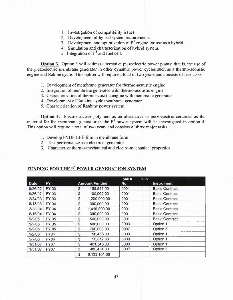
1. Investigation of compatibility issues. 2. Development of hybrid system requirements. 3. Development and optimization of P3 engine for use as a hybrid. 4. Simulation and characterization of hybrid system. 5. Integration of P3 and fuel cell.
Option 3. Option 3 will address alternative piezoelectric power plants; that is, the use of the piezoelectric membrane generator in other dynamic power cycles such as a thermo-acoustic engine and Rakine cycle. This option will require a total of two years and consists of five tasks.
1. Development of membrane generator for thermo-acoustic engine 2. Integration of membrane generator with thermo-acoustic engine 3. Characterization of thermoacoustic engine with membrane generator 4. Development of Rankine cycle membrane generator 5. Characterization of Rankine power system
Option 4. Electrostrictive polymers as an alternative to piezoelectric ceramics as the material for the membrane generator in the P3 power system will be investigated in option 4. This option will require a total of two years and consists of three major tasks.
1. Develop PVDFTrFE film in membrane form 2. Test performance as a electrical generator 3. Characterize thermo-mechanical and electro-mechanical properties
FUNDING FOR THE P3 POWER GENERATION SYSTEM
Date FY Amount Funded SMDC Clin
No. Instrument 9/26/02 FY03 $ 105,851.00 0001 Basic Contract 9/26/02 FY03 $ 100,000.00 0001 Basic Contract 2/24/03 FY03 $ 1,200,000.00 0001 Basic Contract 8/18/03 FY04 $ 300,000.00 0001 Basic Contract 2/20/04 FY04 $ 1,410,000.00 0001 Basic Contract 6/16/04 FY04 $ 300,000.00 0001 Basic Contract 5/9/05 FY05 $ 500,000.00 0001 Basic Contract 5/9/05 FY05 $ 500,000.00 0003 Option 1 5/9/05 FY05 $ 700,000.00 0007 Option 3 5/2/06 FY06 $ 50,438.00 0003 Option 1 5/2/06 FY06 $ 16,812.00 0003 Option 1 1/31/07 FY07 $ 461,546.00 0003 Option 1 1/31/07 FY07 $ 488,454.00 0007 Option 3
$ 6,133,101.00
43