Embed Size (px)
Citation preview

Green & Innovative Lubrification Devices Society : GDTech
Study ref : 267617-GILD
Indices : - Project Periodic Report
Final (years 2013 to 2016)
Project Periodic Report – Period #2 (year 2014) page 1 / 32
GDTech
Final Project Report (years 2013 to 2016)
Written by: Th. WALTREGNY
(LEAR)
Date: 30th March 2017 (update)
Visa
Approved by: M. Bruyneel
(Scientific Director)
Date: 30th March 2017 (update)
Visa
Green & Innovative Lubrification Devices Society : GDTech
Study ref : 267617-GILD
Indices : - Project Periodic Report
Final (years 2013 to 2016)
Project Periodic Report – Period #2 (year 2014) page 2 / 32
Status of the issues
Issues and references Incorporated modifications
.......................................... ..........................................
.......................................... ..........................................
.......................................... ..........................................
.......................................... ..........................................
Recipient
Society Name
Safran Aero Boosters (Safran group) Laurent ARNAUD (Topic Manager)
.......................................... ..........................................
.......................................... ..........................................
.......................................... ..........................................

Green & Innovative Lubrification Devices Society : GDTech
Study ref : 267617-GILD
Indices : - Project Periodic Report
Final (years 2013 to 2016)
Project Periodic Report – Period #2 (year 2014) page 3 / 32
TABLE OF CONTENTS
1. Global project objectives ...................................................................................................... 4 2. Detailed project objectives per period ................................................................................... 6 3. Work achievements per period ............................................................................................. 8 4. Deliverables & Milestones during the project: ..................................................................... 31 5. Project management during the period ............................................................................... 32 6. Dissemination .................................................................................................................... 32 7. Encountered issues ............................................................................................................ 32

Green & Innovative Lubrification Devices Society : GDTech
Study ref : 267617-GILD
Indices : - Project Periodic Report
Final (years 2013 to 2016)
Project Periodic Report – Period #2 (year 2014) page 4 / 32
1. Global project objectives
Preliminary notes:
• the project is issued from the "JTI-CleanSky-2009-2-SAGE-02-003" Call for Proposal (CFP)
• initial project starting date was set around may 2010
• however, due to significant lack of availability for the inputs (from Safran-Snecma), the Topic Manager (Safran Techspace aero) has decided to postpone the project's starting date until January 2013 (see Amendment #1 of the Grant Agreement)
• moreover, according with Topic Manager (TM), in order to realize the updated work scope of the 3rd period, the project has been extended to 31/12/2016 (see Amendment #2 of the Grant Agreement)
1st period: According with the previous planning shift and as defined in the update Description of Work (DoW), the objective of 1st period was to achieve analytical and numerical engineering assessment on the <TRL2 lubrication devices. note: the selected equipment was the heat exchanger At the beginning of the project, GDTech has been invited to be present on the Topic Manager (Techspace aero) site of Milmort (Liège – Belgium). At that time, Techspace aero had not many experiences about the heat exchanger, it has so been decided to start from "scratch". 2nd period: According with the update Description of Work (DoW), the objective of 2nd period was to achieve CAD design and numerical engineering assessment on the <TRL4 lubrication devices. note: the selected equipment was the oil tank In order to achieve TRL4 stage, a vibration test tooling must be designed, assessed, reviewed and calibrated. 3rd period: According to the update Description of Work (DoW), the objective of 3rd period was to lead FEM analysis to the TRL5 on lubrication devices. The 3rd period is focused on FEA and test correlations (pyramid bottom-up approach). note: the selected equipment was the oil tank

Green & Innovative Lubrification Devices Society : GDTech
Study ref : 267617-GILD
Indices : - Project Periodic Report
Final (years 2013 to 2016)
Project Periodic Report – Period #2 (year 2014) page 5 / 32

Green & Innovative Lubrification Devices Society : GDTech
Study ref : 267617-GILD
Indices : - Project Periodic Report
Final (years 2013 to 2016)
Project Periodic Report – Period #2 (year 2014) page 6 / 32
2. Detailed project objectives per period
1st period: The following activities have been realized:
• Kick-off-Meeting
• Acquisition and analysis of the SAGE-2 specifications
• Research about the existing technologies and concepts (cf. from standard State-of-the-Art advanced proof of concept)
note: at that time, additive manufacturing processes have not been investigated
• Definition of the Heat Exchanger Development Plan the goal was to determine the roadmap to follow in order to design and validate the equipment
note: according with TM, the associated deliverable is the "D3 - Heat Exchanger Development Plan "
• Thermal sizing to goal was to determine a realistic thermal sizing
• Design activities the goal was to have a realistic overview of the volume to be further integrated in the SAGE-2 engine environment.
note: according with TM, the associated deliverable is the "D4 – 3D Models "
• Numerical assessment the goal was to develop numerical model in order to help the thermal sizing
notes:
- at that stage, only the Computational Fluid Dynamics (CFD) approach has been selected by the TM
- according with TM, the associated deliverable is the "D5 – FEA/analytical results "
• Concept Design Review (CDR)
notes:
- according with TM, the associated deliverable is the "D6 – TRL2 Review"
- intermediate technical meetings and reviews have been realized

Green & Innovative Lubrification Devices Society : GDTech
Study ref : 267617-GILD
Indices : - Project Periodic Report
Final (years 2013 to 2016)
Project Periodic Report – Period #2 (year 2014) page 7 / 32
2nd period: The following activities have been realized:
a) Kick-off-Meeting of the WP3
b) Definition of the FEA roadmap and test tooling specifications note: according with TM, the associated deliverable is the "D7 - Oil Tank Development
Plan"
c) Iterative design activities of the oil tank HCF test tooling note: associated deliverable is the "D8 - Oil Tank Vibration Test 3D Models"
d) Numerical assessment of the HCF test set-up the goal was to validate the dynamic behavior of the tooling. Moreover, the HCF living has been assessed (e.g. bolted assembly, welded joints…) note: associated deliverable is the "D9 - Oil Tank Vibration Test FEA report"
e) Concept Design Review (CDR) notes: - intermediate technical meetings and reviews have been realized - associated deliverable is the "D10 - Oil Tank Vibration Tool Concept Design Review"
3rd period: The following activities have been realized:
f) Kick-off-Meeting of the WP4: definition of the FEA roadmap and required tests (with specification test) note: according with TM, the associated deliverable is the "D11 - KOM"
g) Vibration tests on single parts and on assembled parts in a laboratory. Comparison between numerical results and the experimental measurements. The best model procedure is identified at each step of the pyramid approach. note: the associated deliverable is the "D12 – Test Correlation"
h) Numerical assessment on the oil tank (single and assembled parts). Study of assembly conditions: implementation of gluing, bolted connection, clamping, … Mesh study on each part. The more suitable model is identified for each studied assembly condition. note: the associated deliverable is the "D13 – FEA Optimisation"
i) Presentation of the main results notes: - intermediate technical meetings and reviews have been realized - the associated deliverable is the "D14 – TRL5 Review"

Green & Innovative Lubrification Devices Society : GDTech
Study ref : 267617-GILD
Indices : - Project Periodic Report
Final (years 2013 to 2016)
Project Periodic Report – Period #2 (year 2014) page 8 / 32
3. Work achievements per period
1st period: During the 1st period (year 2013), activities have been achieved on 2 WPs:
a) Management planning (D1) & management plan (D2) b) TRL<2 engineering & assessments
Presentation of the Sage-2 engine demonstrator:
The SAGE-2 demonstrator is an Open Rotor engine. Basically, the gas generator is a modified M88 engine core, the counter rotating fan blades are located at the rear of the engine. Those are connected to the rotors through a gearbox located in the MSF section (downstream of the turbine and upstream of the fan stages). As well for GTF commercial engines (or even turboprop), the gearbox efficiency (even high) lead to have thermal loss that heat the oil that have to be cooled down through the heat exchanger (Air Cooled Oil Cooler). The design (compactness) and thermal efficiency of the ACOC are the main concerns to assess. Moreover, the heat exchanger will be located in the engine nacelle and is subject to high temperature and high vibration (HCF) environment. Important note: During the project, Safran-Snecma has informed Safran-Techspace aero (=TM) that the equipment (that had to be initially manufactured and delivered by Techspace) will not be directly installed in the nacelle (=engine environment) but in a slave position (away from the engine) based on this decision, Techspace aero has inform GDTech that the activity will remain on a study level. a) Management tasks (WP1): Because the GILD project is a single member one, the management activities have been focused on the setup of communication with the Topic Manager focal point (initially not identified). During the period, the level-1 planning (D1) and the Project Management Plan (D2) have been defined and submitted. b) TRL <2 engineering tasks (WP2): From an historical point of view, the Topic Manager (Techspace Aero Safran group) has not a strong experience legacy about heat exchanger.

Green & Innovative Lubrification Devices Society : GDTech
Study ref : 267617-GILD
Indices : - Project Periodic Report
Final (years 2013 to 2016)
Project Periodic Report – Period #2 (year 2014) page 9 / 32
Documents research of the existing state-of-the-art has been realized covering technological aspects (e.g. materials, assembly, design, assessment…). Following pictures illustrate the type of acquired data:
2nd period: During the 2nd period (year 2014), activities have been achieved on 2 WPs:
a) Management (coordination with TM) b) TRL<4 engineering & assessments
On Sage-2 demonstrator, the gearbox requires significant amount of oil flow rate. In addition, with the heat exchanger (see 1st period), the oil tank is a major equipment in the oil system. It has several functions, the 1st one is of course to manage the oil quantity but it also realizes the function of air-oil separator and oil monitoring. The design (compactness) and mechanical behavior (including HCF) of the oil tank are the main concerns to assess. The standard assessed mechanical conditions are:
• Dynamic assessment (frequencies & modes identification)
• Dynamic Response (harmonic approach) assessment (with notching)
• Thermal expansion load cases
• Pressure load cases (including proof and burst pressures)
• Fan Blade Out (FBO) load cases (_g static approach)
• Assembly Pre-loads analysis
a) Management tasks (WP1): Because the GILD project is a single member one, the management activities have been focused on communication activities with the Topic Manager focal point.
HCF behavior to correlate with tests

Green & Innovative Lubrification Devices Society : GDTech
Study ref : 267617-GILD
Indices : - Project Periodic Report
Final (years 2013 to 2016)
Project Periodic Report – Period #2 (year 2014) page 10 / 32
b) TRL <4 engineering tasks (WP3): From an historical point of view, the Topic Manager (Techspace Aero Safran group) has a strong experience legacy about oil tank but in commercial engines environment using damped solutions. The oil tank design and validation require to:
o manage the "hard mounting" configuration o manage the Finite Element Assessment correlation vs. tests
in order to achieve those challenges, it was mandatory to design and validate HCF dynamic test tooling. b.1) Engineering & design: The main design constrain was set but the dynamic response of the tooling. Indeed, in order to interact with the genuine oil tank modes (especially the 1st ones at lower frequency), it was important to raise the tooling modes at higher frequency. This induces to have the stiffest tooling but also lightest one (cf. also limited by the shaker weight capability). Several designs have been engineered and presented to the TM as trade-off review. Following pictures illustrates some of the designed and assessed tooling and configurations:
Concept #1
Concept #2
Concept #3
Concept #4

Green & Innovative Lubrification Devices Society : GDTech
Study ref : 267617-GILD
Indices : - Project Periodic Report
Final (years 2013 to 2016)
Project Periodic Report – Period #2 (year 2014) page 11 / 32
Finally, the design has converged toward the "pyramid solution". The following pictures illustrate CAD model and drawings extracts:
Overview
Upper bracket
Right bracket
Left bracket
note: see "D8 - Oil Tank Vibration Test 3D Models" for more details about CAD model and drawings.

Green & Innovative Lubrification Devices Society : GDTech
Study ref : 267617-GILD
Indices : - Project Periodic Report
Final (years 2013 to 2016)
Project Periodic Report – Period #2 (year 2014) page 12 / 32
b.2) FE numerical assessments: During design process, numerical models have been achieved in order to optimize the 1st tooling frequency and to avoid anti-resonance behavior with the oil tank. Moreover, the last converged "pyramid" design has been assessed in order to validate the tooling assembly (including bolted & welded joints) and the test set-up (including the oil tank). The following pictures illustrate the mechanical Finite Element Model:
Oil tank in engine set-up
Oil tank in test set-up
Mesh illustration of the upper bracket
Mesh illustration of the lower brackets
Mesh illustration of the internal parts
Illustration of the oil level
note: see "D9 - Oil Tank Vibration Test FEA report" for more details about model and boundary conditions.
Green & Innovative Lubrification Devices Society : GDTech
Study ref : 267617-GILD
Indices : - Project Periodic Report
Final (years 2013 to 2016)
Project Periodic Report – Period #2 (year 2014) page 13 / 32
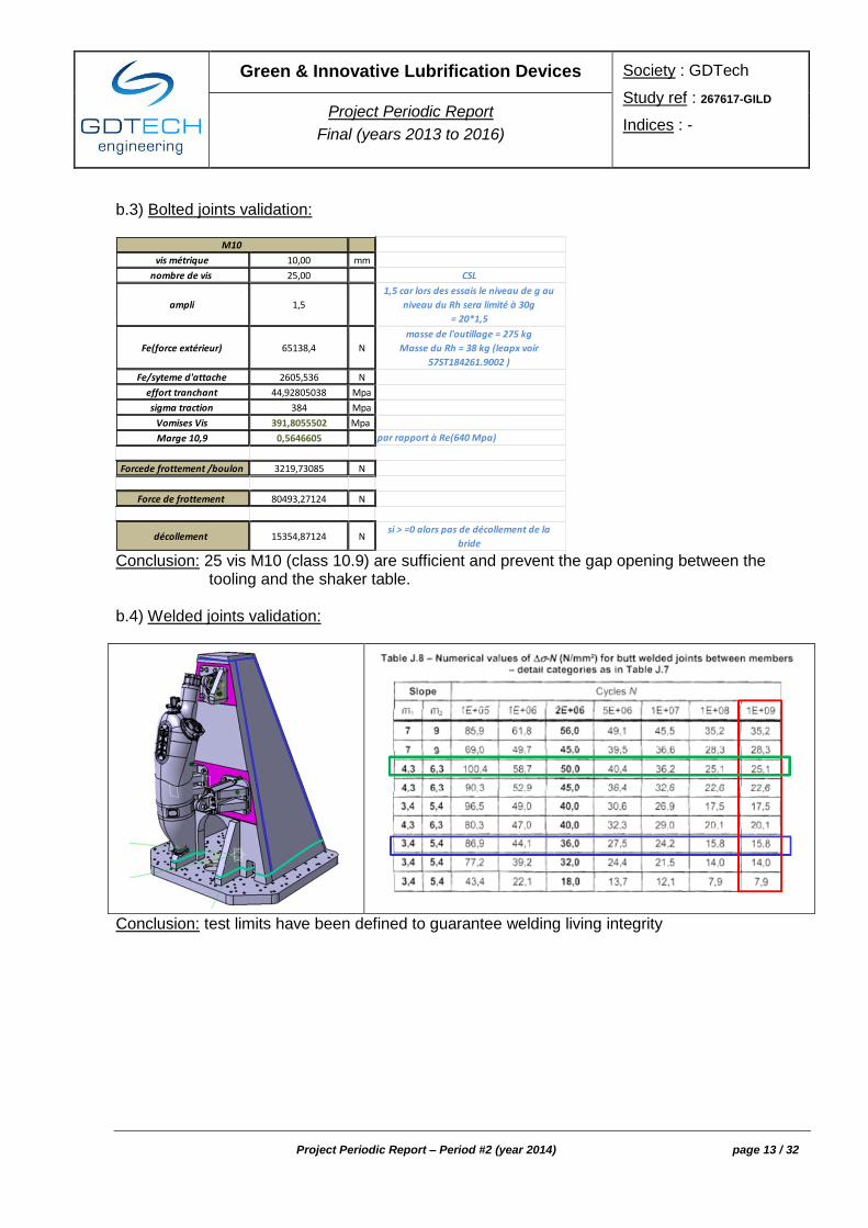
b.3) Bolted joints validation:
vis métrique 10,00 mm
nombre de vis 25,00 CSL
ampli 1,5
1,5 car lors des essais le niveau de g au
niveau du Rh sera limité à 30g
= 20*1,5
Fe(force extérieur) 65138,4 N
masse de l'outillage = 275 kg
Masse du Rh = 38 kg (leapx voir
57ST184261.9002 )
Fe/syteme d'attache 2605,536 N
effort tranchant 44,92805038 Mpa
sigma traction 384 Mpa
Vomises Vis 391,8055502 Mpa
Marge 10,9 0,5646605 par rapport à Re(640 Mpa)
Forcede frottement /boulon 3219,73085 N
Force de frottement 80493,27124 N
décollement 15354,87124 Nsi > =0 alors pas de décollement de la
bride
M10
Conclusion: 25 vis M10 (class 10.9) are sufficient and prevent the gap opening between the
tooling and the shaker table. b.4) Welded joints validation:
Conclusion: test limits have been defined to guarantee welding living integrity

Green & Innovative Lubrification Devices Society : GDTech
Study ref : 267617-GILD
Indices : - Project Periodic Report
Final (years 2013 to 2016)
Project Periodic Report – Period #2 (year 2014) page 14 / 32
3rd period: During the 3rd period (years 2015 & 2016), the activities carried out for each WP are summarized:
a) WP1: Numerical investigation on academic cases good-practice rules b) WP2: FEA on the single parts and vibration tests correlation & optimisation c) WP3: FEA on assembled parts and vibration tests correlation & optimisation d) WP4: vibration tests of the oil tank with the fluid
a) Numerical investigation on academic cases (WP1)
The considered academic case is a cantilever beam with a concentrated tip load. First, a convergence analysis is carried out to validate the mesh type. The tip displacement is compared for each element hypothesis available in the SAMCEF software.

Green & Innovative Lubrification Devices Society : GDTech
Study ref : 267617-GILD
Indices : - Project Periodic Report
Final (years 2013 to 2016)
Project Periodic Report – Period #2 (year 2014) page 15 / 32
The corresponding comparison in terms of stresses is represented in the next figure.
The comparison in terms of natural frequencies is grouped according to the main deformation of the mode shape: the first bending and torsion modes are represented in the following:

Green & Innovative Lubrification Devices Society : GDTech
Study ref : 267617-GILD
Indices : - Project Periodic Report
Final (years 2013 to 2016)
Project Periodic Report – Period #2 (year 2014) page 16 / 32
Conclusions of WP1:
The mesh with HEXA DEG 1 must be created with a minimum of 3 elements through the thickness.
The mesh with HEXA DEG 2 must be created with a minimum of 2 elements through the thickness.
The use of the mesh with TETRA DEG 1 should be avoided: displacement, stress and natural frequencies are wrong.
The convergence of the TETRA DEG 2 mesh is slower than that of the HEXA DEG 2 mesh.
When the thickness of the beam is very small, “Solid Shell” and “Mindlin” hypothesis can be favourably used.

Green & Innovative Lubrification Devices Society : GDTech
Study ref : 267617-GILD
Indices : - Project Periodic Report
Final (years 2013 to 2016)
Project Periodic Report – Period #2 (year 2014) page 17 / 32
b) FEA and vibration tests on single parts (WP2) All the details about the experimental tests are in the deliverable "D12 – Test Correlation". The numerical investigations for each part is detailed in "D13 – FEA Optimisation". b.1) Upper bracket
Reference test for the correlation: modal analysis of an impact test in “free-free” conditions.
The model of the rivets should be realized with a rigid body link between a central node and the hole surfaces of the components.
The mesh study show that a mesh size of 2 mm is sufficient, with 2 elements through the thickness.
Green & Innovative Lubrification Devices Society : GDTech
Study ref : 267617-GILD
Indices : - Project Periodic Report
Final (years 2013 to 2016)
Project Periodic Report – Period #2 (year 2014) page 18 / 32
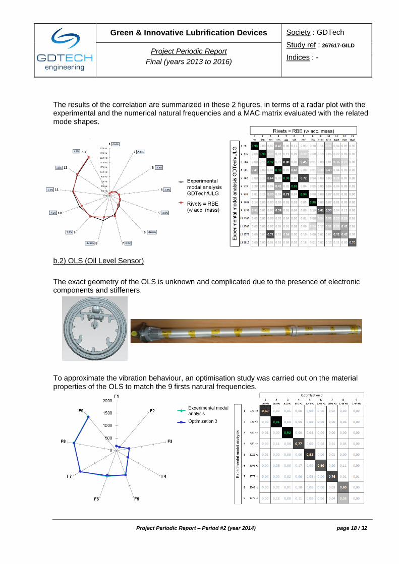
The results of the correlation are summarized in these 2 figures, in terms of a radar plot with the experimental and the numerical natural frequencies and a MAC matrix evaluated with the related mode shapes.
b.2) OLS (Oil Level Sensor)
The exact geometry of the OLS is unknown and complicated due to the presence of electronic components and stiffeners.
To approximate the vibration behaviour, an optimisation study was carried out on the material properties of the OLS to match the 9 firsts natural frequencies.

Green & Innovative Lubrification Devices Society : GDTech
Study ref : 267617-GILD
Indices : - Project Periodic Report
Final (years 2013 to 2016)
Project Periodic Report – Period #2 (year 2014) page 19 / 32
The mesh associates with this optimisation process is illustrated in the next figure (without stiffeners).
b.3) Oil Tank
As the geometry of the oil tank is very simple, no experimental tests have been performed.
Only a numerical study was conducted.
Regarding the model of the oil tank skin, 3 element hypotheses were envisaged: solid hypothesis, shell hypothesis and solid shell hypothesis. The mesh convergence study is represented in the following to highlight the performance of each element type.
Hexa DEG 2 (4mm) // Hexa DEG 1 (1.5mm) // Heterosis (8 mm)
Based on the achieved numerical results, the « Solid Shell » and « Mindlin » hypotheses should be avoided.

Green & Innovative Lubrification Devices Society : GDTech
Study ref : 267617-GILD
Indices : - Project Periodic Report
Final (years 2013 to 2016)
Project Periodic Report – Period #2 (year 2014) page 20 / 32
A mesh study was carried out on the welded accessories (servicing panel, belt, interfaces, …). A mesh size of 4 mm is selected to obtain reliable results.
The choice of the most relevant modelling must be made based on the « Error – CPU » graph below.
b.4) Tooling
The reference experimental results for the correlation are given by the modal analysis of the measurements collected during an impact test in “free-free” boundary conditions.

Green & Innovative Lubrification Devices Society : GDTech
Study ref : 267617-GILD
Indices : - Project Periodic Report
Final (years 2013 to 2016)
Project Periodic Report – Period #2 (year 2014) page 21 / 32
The correlation with the best numerical model is represented in the next figures. It is woth noting that the 3D geometry should not be simplified, otherwise the natural frequencies would be influenced.
c) FEA and vibration tests on assembled parts (WP3)
All the details about the experimental tests are in the deliverable "D12 – Test Correlation". The numerical investigations for each assembly are detailed in "D13 – FEA Optimisation". c.1) Brackets & Tooling
The reference tests for the correlation are three logarithmic sine-sweeps at low level (0.1g) along the 3 structural directions.

Green & Innovative Lubrification Devices Society : GDTech
Study ref : 267617-GILD
Indices : - Project Periodic Report
Final (years 2013 to 2016)
Project Periodic Report – Period #2 (year 2014) page 22 / 32
A mesh study of the bracket supports was realized. A mesh size of 4 mm was sufficient to give reliable results. The mesh of the assembly is illustrated in the next figure (tooling, support and bracket).
The model of the clamping of the tooling to the shaker interface was studied. The most relevant model is the clamping of the whole contact surface:

Green & Innovative Lubrification Devices Society : GDTech
Study ref : 267617-GILD
Indices : - Project Periodic Report
Final (years 2013 to 2016)
Project Periodic Report – Period #2 (year 2014) page 23 / 32
The way to connect the brackets and the supports to the tooling was also studied. The screw/insert assembly must be modelled with rigid links between the screw head surface and the drilling surface for a length corresponding to the first 3 threads of the inserts.
The numerical modes of this model are compared to the experimental data.
When multiple sine-sweep tests at different amplitudes of the base acceleration are carried out, the effects of the nonlinearities on the dynamic response of the assembly can be estimated. In presence of nonlinearities the modal parameters (natural frequencies, damping ratios and mode shapes) change with the amplitude of vibrations, and the correlation of the numerical finite element model becomes a challenging task. To this end, the effects of the nonlinearities introduced by the bolted connections are investigated to identify the dependency of the modal parameters on the vibration energy.

Green & Innovative Lubrification Devices Society : GDTech
Study ref : 267617-GILD
Indices : - Project Periodic Report
Final (years 2013 to 2016)
Project Periodic Report – Period #2 (year 2014) page 24 / 32
The identification of the nonlinear connections between each bracket and the tooling is carried out. The time responses of the accelerometers placed at the tip of each bracket recorded during the high-level vibration test are compared with the corresponding measures at low level. The following figure the time response at resonance measured by the accelerometer placed on the upper bracket is represented to compare the difference in frequency and in amplitude between the high-level and the low-level testes.
Although the vertical axes are properly scaled to compensate for the different excitation amplitudes, the difference of the peak values is remarkable: when the base acceleration is 1g the amplitude of oscillation reaches 45g, instead of the expected 100g (ten times 10g, which is the response when the base acceleration is equal to 0.1g). Moreover, the envelopes of the time responses follow two different trends around the resonance, whose frequency shifts of about 3%, from 173Hz to 168 Hz. The Acceleration Surface Method is implemented between the sensor on the bracket and the sensor placed on the tooling in correspondence of the bracket to evaluate the nonlinear restoring force due to the bolt connections. Substantially, the results obtained from the data collected on the left and right brackets are similar and also coherent with the physical behavior of bolted connections.
The figures highlight a softening behavior typical of loose connections along the in-plane directions.

Green & Innovative Lubrification Devices Society : GDTech
Study ref : 267617-GILD
Indices : - Project Periodic Report
Final (years 2013 to 2016)
Project Periodic Report – Period #2 (year 2014) page 25 / 32
Moreover, the response of the upper bracket shows an additional resonance between the first two modes at about 56Hz (as represented in the following figures). It is clearly visible that in this case the amplitude of the third harmonic is as high as the main harmonic. This means that a not negligible part of the energy is transferred to higher frequencies. Moreover, at 3 times the forcing frequency (that is about 168Hz) another mode of the bracket can be isolated, as already shown. It can be concluded that a modal interaction is occurring.
c.2) Oil Tank & Brackets & Tooling
The reference tests for the correlation are the logarithmic sine sweeps at low level (0.1g) along the 3 structural directions.

Green & Innovative Lubrification Devices Society : GDTech
Study ref : 267617-GILD
Indices : - Project Periodic Report
Final (years 2013 to 2016)
Project Periodic Report – Period #2 (year 2014) page 26 / 32
The oil tank is meshed using the Heterosis elements, as advised after the numerical investigations of the oil tank skin. The mesh of the tooling, the support and the brackets is already described in the “Brackets & Tooling” assembly.
The first experimental natural frequency is higher than its numerical counterpart (about 10%). The model is more flexible than the real structure (according to the test). The experimental estimates suggest that the tooling and the supports do not participate to this mode, whereas the 3 brackets and the oil tank contribute to the mode shape. Conversely, in the numerical model also the supports of the brackets participate to the mode. Therefore, in the numerical model, the assembly between the brackets and the oil tank is not enough rigid. Similar remarks hold for the higher modes. It is recommended to further investigate to improve the model correlation with the experimental results. A possible solution could be related to the selection of a different way of assembling the parts in function of the stiffness of the single parts and of the connecting elements (rigid bodies, thin bodies, tightening torque, …). Another recommendation is to study the influence of the nonlinearities as in the previous case (without tank).
c.3) OLS & Brackets & Tooling
The reference tests for the correlation are the logarithmic sine sweeps at low level (0.1g) along the 3 structural directions.

Green & Innovative Lubrification Devices Society : GDTech
Study ref : 267617-GILD
Indices : - Project Periodic Report
Final (years 2013 to 2016)
Project Periodic Report – Period #2 (year 2014) page 27 / 32
The presence of the OLS during the test shifts the natural frequencies. When the mode shape is global (low oil tank elastic deformation), only the OLS mass influences the natural frequencies: they shift towards lower values. When the oil tank elastic deformation is not negligible, the OLS contributes to the stiffnes of the oil tank and the natural frequencies shift towards higher values. The presence of accelerometers on the OLS during the test allowed the identication of some local modes of the OLS.
d) Vibration tests of the oil tank with the fluid (WP4)
All the details about the experimental tests are in the deliverable "D12 – Test Correlation".
d.1) Fluid
The reference tests for the correlation are the logarithmic sine sweeps at low level (0.1g) along the 3 structural directions. Three fluid levels were tested (4 litres, 9.9 litres and 18.8 litres).

Green & Innovative Lubrification Devices Society : GDTech
Study ref : 267617-GILD
Indices : - Project Periodic Report
Final (years 2013 to 2016)
Project Periodic Report – Period #2 (year 2014) page 28 / 32
The influence of the fluid level on the measured frequencies is reported in the next table.
Level 1 Level 2 Level 3 Main contribution
F1 71.5 Hz 59.5 Hz 56 Hz
65.5 Hz Bottom Oil Tank
F2 119 Hz 113 Hz 106 Hz 110 Hz
Oil Tank + Up Bracket
F3 137 Hz 141 Hz
133 Hz 118 Hz 120 Hz
Global (test X) Global (test Y)
F4 156 Hz 154 Hz 146 Hz 151 Hz
Global (test X) Global (test Y)
F5 160 Hz 158 Hz Oil Tank + Up Bracket
F6 167 Hz 163 Hz Oil Tank + Up Bracket (test Y)
F7 171 Hz 168 Hz 162 Hz Oil Tank + Brackets (test X)
F8 181 Hz 174 Hz Oil Tank + Left Bracket (test Y)
Green & Innovative Lubrification Devices Society : GDTech
Study ref : 267617-GILD
Indices : - Project Periodic Report
Final (years 2013 to 2016)
Project Periodic Report – Period #2 (year 2014) page 29 / 32
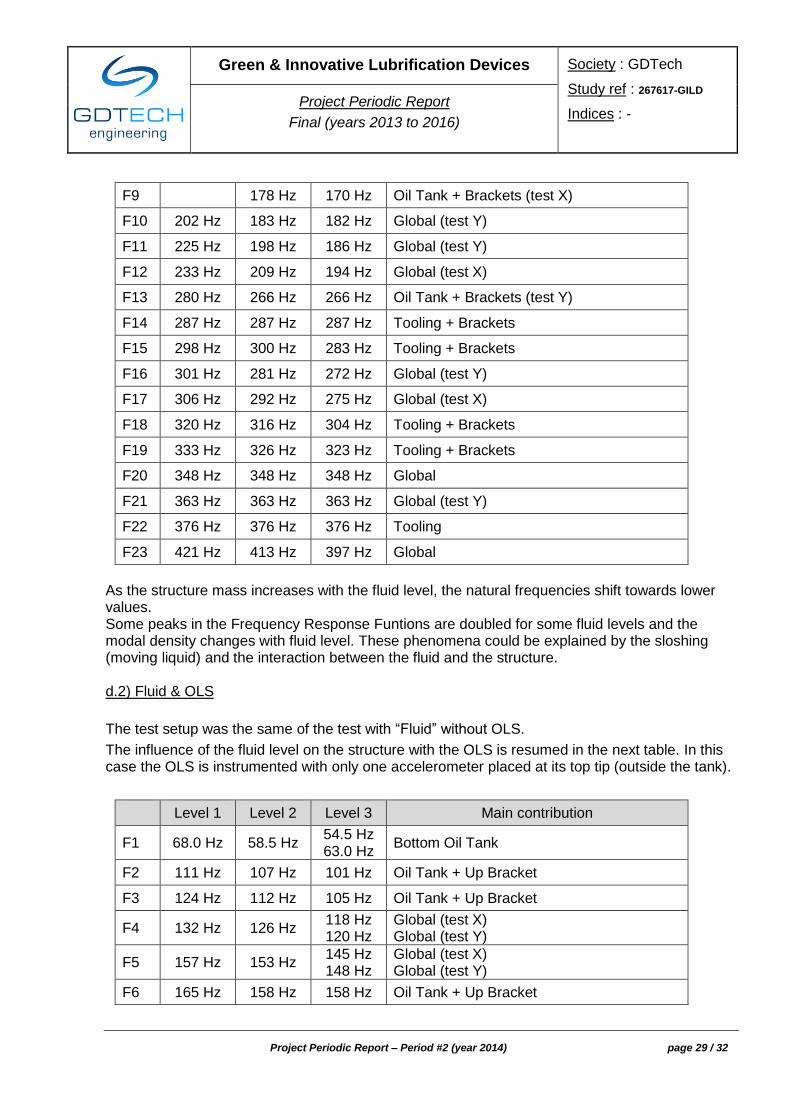
F9 178 Hz 170 Hz Oil Tank + Brackets (test X)
F10 202 Hz 183 Hz 182 Hz Global (test Y)
F11 225 Hz 198 Hz 186 Hz Global (test Y)
F12 233 Hz 209 Hz 194 Hz Global (test X)
F13 280 Hz 266 Hz 266 Hz Oil Tank + Brackets (test Y)
F14 287 Hz 287 Hz 287 Hz Tooling + Brackets
F15 298 Hz 300 Hz 283 Hz Tooling + Brackets
F16 301 Hz 281 Hz 272 Hz Global (test Y)
F17 306 Hz 292 Hz 275 Hz Global (test X)
F18 320 Hz 316 Hz 304 Hz Tooling + Brackets
F19 333 Hz 326 Hz 323 Hz Tooling + Brackets
F20 348 Hz 348 Hz 348 Hz Global
F21 363 Hz 363 Hz 363 Hz Global (test Y)
F22 376 Hz 376 Hz 376 Hz Tooling
F23 421 Hz 413 Hz 397 Hz Global
As the structure mass increases with the fluid level, the natural frequencies shift towards lower values. Some peaks in the Frequency Response Funtions are doubled for some fluid levels and the modal density changes with fluid level. These phenomena could be explained by the sloshing (moving liquid) and the interaction between the fluid and the structure. d.2) Fluid & OLS
The test setup was the same of the test with “Fluid” without OLS.
The influence of the fluid level on the structure with the OLS is resumed in the next table. In this case the OLS is instrumented with only one accelerometer placed at its top tip (outside the tank).
Level 1 Level 2 Level 3 Main contribution
F1 68.0 Hz 58.5 Hz 54.5 Hz 63.0 Hz
Bottom Oil Tank
F2 111 Hz 107 Hz 101 Hz Oil Tank + Up Bracket
F3 124 Hz 112 Hz 105 Hz Oil Tank + Up Bracket
F4 132 Hz 126 Hz 118 Hz 120 Hz
Global (test X) Global (test Y)
F5 157 Hz 153 Hz 145 Hz 148 Hz
Global (test X) Global (test Y)
F6 165 Hz 158 Hz 158 Hz Oil Tank + Up Bracket

Green & Innovative Lubrification Devices Society : GDTech
Study ref : 267617-GILD
Indices : - Project Periodic Report
Final (years 2013 to 2016)
Project Periodic Report – Period #2 (year 2014) page 30 / 32
F7 169 Hz 169 Hz Oil Tank + Up Bracket (test X)
F8 180 Hz 183 Hz 176 Hz Global (test Y)
F9 196 Hz 179Hz 170 Hz Oil Tank + Brackets (test X)
F10 216 Hz 191 Hz Global (test Y)
F11 227 Hz 203 Hz 182 Hz Global (test Y)
F12 265 Hz 266 Hz 266 Hz Oil Tank + Brackets (test Y)
F13 280 Hz 281 Hz Global (Test Y)
F14 286 Hz 285 Hz 283 Hz Tooling + Brackets
F15 297 Hz 301 Hz 287 Hz Global
F16 300 Hz 305 Hz
291 Hz 272 Hz Global (test Y) Global (test X)
F17 317 Hz 317 Hz 303 Hz Tooling + Brackets (test X)
F18 324 Hz 325 Hz 323 Hz Tooling + Brackets (test Y)
F19 340 Hz 348 Hz
338 Hz 348 Hz
348 Hz Global
F20 363 Hz 363 Hz 363 Hz Global (test Y)
F21 377 Hz 377 Hz 375 Hz Tooling
F22 423 Hz 434 Hz
414 Hz 420 Hz
392 Hz Global
As the structure mass increases with the fluid level, the natural frequencies decease. Some peaks in the FRFs are doubled for some fluid level and the modal density changes with the fluid level. These phenomena are exacerbated with respect to the tests without OLS: there could be an interaction between the fluid, the OLS and the oil tank.
Green & Innovative Lubrification Devices Society : GDTech
Study ref : 267617-GILD
Indices : - Project Periodic Report
Final (years 2013 to 2016)
Project Periodic Report – Period #2 (year 2014) page 31 / 32
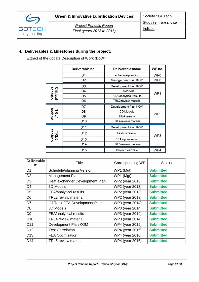
4. Deliverables & Milestones during the project:
Extract of the update Description of Work (DoW):
Deliverable n°
Title Corresponding WP Status
D1 Schedule/planning Version WP1 (Mgt) Submitted
D2 Management Plan WP1 (Mgt) Submitted
D3 Heat exchanger Development Plan WP2 (year 2013) Submitted
D4 3D Models WP2 (year 2013) Submitted
D5 FEA/analytical results WP2 (year 2013) Submitted
D6 TRL2 review material WP2 (year 2013) Submitted
D7 Oil Tank FEA Development Plan WP3 (year 2014) Submitted
D8 3D Models WP3 (year 2014) Submitted
D9 FEA/analytical results WP3 (year 2014) Submitted
D10 TRL4 review material WP3 (year 2014) Submitted
D11 Development Plan KOM WP4 (year 2015) Submitted
D12 Test Correlation WP4 (year 2016) Submitted
D13 FEA Optimisation WP4 (year 2016) Submitted
D14 TRL5 review material WP4 (year 2016) Submitted

Green & Innovative Lubrification Devices Society : GDTech
Study ref : 267617-GILD
Indices : - Project Periodic Report
Final (years 2013 to 2016)
Project Periodic Report – Period #2 (year 2014) page 32 / 32
Milestones n°
Title Corresponding WP Status
M1 KOM–WP2 (year 2013) WP2 (year 2013) Passed
M2 TRL2 review WP2 (year 2013) Passed
M3 KOM–WP3 (year 2014) WP3 (year 2014) Passed
M4 TRL4 review WP3 (year 2014) Passed
M5 KOM WP4 (year 2015) Passed
M6 TRL5 review WP4 (year 2016) Passed
5. Project management during the period
Because the GILD project is a single member one, the management activities have been focused on the setup of communication with the Topic Manager focal point.
6. Dissemination
According with the DoW, several dissemination intents have been achieved and will be (at least during about 12 months after project end). However, according with IPR restrictions (see Topic Manager), those have been limited to (public) generic concerns and not detailed with figures. Nevertheless, 2 main dissemination processes have been realized:
- the project and objectives haves been presented to the ENOVAL (FP7) executive board (MTU, Safran, RR, Avio, ITP,…)
- the project and objectives have been presented during technical & commercial meeting towards several companies (majors, SME) in different activity domains (including automotive,…)
Moreover, our intent is to publish and present a scientific paper presenting the GILD project benefits and to present to a Siemens software user conference. Important note: in order to cover the final multi-physic correlation, the topic will be achieved through 2 further national R&D projects.
7. Encountered issues
At the end of the GILD project (December 2016), all the experimental tests were carried out. However, at that stage, the correlation study is limited to “Brackets & Tooling” step of the pyramidal approach.