Embed Size (px)
Citation preview

Page 1 (191)
Project Number: CELTIC / CP5-026
Project Title: Wireless World Initiative New Radio – WINNER+
Document Type: PU (Public)
Document Identifier: D1.9
Document Title: Final Innovation ReportSource Activity: WP1
Editor: Tommy Svensson, Eric Zinovieff
Authors: Gunther Auer, Mehdi Bennis, Mauro Boldi, Carmen Botella, Loïc Brunel, Emilio Calvanese Strinati, Valeria D’Amico, Amelie
Duchesne, Paolo Greco, Volker Jungnickel, Petri Komulainen, Dimitri Ktenas, Yang Liu, Sylvie Mayrargue, Bruno Melis, Albena
Mihovska, Jose F. Monserrat, Magnus Olsson, Afif Osseiran, Harri Pennanen, Lars Rasmussen, Florian Roemer, Peter Rost, Valentin
Savin, Rainer Schoenen, Serdar Sezginer, Pawel Sroka, Tommy Svensson, Lars Thiele, Antti Tölli, Jaakko Vihriälä, Guillaume Vivier,
Krzysztof Wesolowski, Ming Xiao, Eric Zinovieff Status / Version: 1.0
Date Last changes: 07.04.10
File Name: D1.9.doc
Abstract:
This deliverable is the final innovation report from the innovation workpackage in WINNER+. The document describes the latest innovations and their assessment as well as summarizes the innovations developed in the work package during the project. We analyze the suitability of these innovations as technology enablers for improving current systems, in particular IMT Advanced and beyond.
Keywords:
Resource allocation, carrier aggregation, femtocells, relaying, network coding, MIMO, Quality of Service, coordinated multipoint, IMT Advanced and beyond.
Document History:
12.11.2009 Document created
21.02.2010 Document ready for internal review
14.03.2010 Document ready for external and PCT review
02.04.2010 Final document
WINNER+ D1.9
Version: 1.0 Page 2 (191)
Table of Contents
1. Introduction.......................................................................................... 14
2. Resource Allocation............................................................................ 16 2.1 Introduction........................................................................................................................... 16 2.2 Proposed Innovations............................................................................................................ 16
2.2.1 QoS Scheduling ............................................................................................................. 16 2.2.1.1 Traffic-aware score-based scheduling................................................................... 16 2.2.1.2 QoS scheduler based on utility prediction............................................................. 17
2.2.2 Multi-User MIMO and Coordinated Scheduling ........................................................... 17 2.2.2.1 Low complexity resource allocation in MU SDMA.............................................. 17 2.2.2.2 Interference mitigation (CoMP) based on efficient scheduling............................. 18 2.2.2.3 Decentralised interference avoidance using busy bursts ....................................... 18
2.2.3 Spectrum Access............................................................................................................ 18 2.2.3.1 Spectrum sharing from a game theory perspective................................................ 18 2.2.3.2 Optimisation of the sum throughput...................................................................... 19
2.2.4 Traffic Identification and Load Management ................................................................ 20 2.2.4.1 Automatic traffic characterisation ......................................................................... 20 2.2.4.2 Recursive nonlinear traffic prediction for dynamic resource allocation................ 20 2.2.4.3 Dynamic load management and congestion control.............................................. 21
2.2.5 Efficient MBMS transmission ....................................................................................... 21 2.3 Potential Impacts on Signalling ............................................................................................ 22 2.4 Potential Impacts on Architecture......................................................................................... 22 2.5 Compatibility with LTE and LTE-Advanced........................................................................ 23 2.6 Conclusions........................................................................................................................... 23
3. Carrier Aggregation............................................................................. 25 3.1 Introduction........................................................................................................................... 25
3.1.1 Basic Concepts............................................................................................................... 25 3.1.2 ITU-R Requirements and Implementation in Standards ................................................ 25 3.1.3 Hardware and Legal Limitations.................................................................................... 25 3.1.4 Research Challenges ...................................................................................................... 26
3.2 Proposed Innovations............................................................................................................ 27 3.2.1 MAC implications of carrier aggregation ...................................................................... 27 3.2.2 PHY implications of carrier aggregation ....................................................................... 27 3.2.3 CQI signalling in Carrier Aggregation........................................................................... 28
3.3 Potential Impacts on Signalling and Architecture................................................................. 29 3.4 Potential Impacts on Architecture and Protocols .................................................................. 29 3.5 Compatibility to LTE and LTE-Advanced............................................................................ 30 3.6 Conclusions........................................................................................................................... 30
4. Femtocells............................................................................................ 31 4.1 Introduction........................................................................................................................... 31
4.1.1 General........................................................................................................................... 31 4.1.2 Femtocell Standardization ............................................................................................. 31 4.1.3 Interference Management .............................................................................................. 32
4.2 Proposed Innovations............................................................................................................ 32

WINNER+ D1.9
Version: 1.0 Page 3 (191)
4.2.1 Femtocells with beacons................................................................................................ 32 4.2.2 Coordinated femtocells with ICIC ................................................................................. 32 4.2.3 Self organized femtocells............................................................................................... 33 4.2.4 Femtocells and game theory .......................................................................................... 33
4.3 Expected Performance of Innovations .................................................................................. 33 4.4 Potential Impacts on Signalling and Measurements.............................................................. 34 4.5 Potential Impacts on Architecture and Protocols .................................................................. 34 4.6 Compatibility to LTE and Implementation Complexity ....................................................... 35 4.7 Conclusions........................................................................................................................... 35
5. Relaying................................................................................................ 37 5.1 Introduction........................................................................................................................... 37 5.2 Proposed Innovations............................................................................................................ 37
5.2.1 Scheduling ..................................................................................................................... 37 5.2.1.1 Relay capable scheduling for combined half/full duplex FDD ............................. 37 5.2.1.2 Relay-capable flow management for QoS scheduling........................................... 38 5.2.1.3 HYGIENE scheduling with relays ........................................................................ 38
5.2.2 Cooperative Relaying .................................................................................................... 38 5.2.2.1 A Multi-user MIMO relaying approach ................................................................ 38 5.2.2.2 Integration CoMP and relaying ............................................................................. 39 5.2.2.3 Distributed space time coding ............................................................................... 39 5.2.2.4 Distributed LDPC coding...................................................................................... 40
5.2.3 Increased traffic density/Two way relaying................................................................... 40 5.3 Potential Impacts on Signalling ............................................................................................ 41 5.4 Potential Impacts on Architecture......................................................................................... 41 5.5 Compatibility to LTE and LTE-Advanced............................................................................ 42 5.6 Conclusions........................................................................................................................... 42
6. Network Coding ................................................................................... 44 6.1 Introduction........................................................................................................................... 44 6.2 Proposed Innovations............................................................................................................ 44
6.2.1 Non Binary Network Coding in uplink relaying scenario.............................................. 44 6.2.1.1 Network Coding for cooperating mobiles ............................................................. 44 6.2.1.2 Network coding for multiple-user multiple-relay systems .................................... 45 6.2.1.3 Performance .......................................................................................................... 45
6.2.2 Network Coding for uplink relay-based wireless communication systems ................... 46 6.2.2.1 User Grouping ....................................................................................................... 46 6.2.2.2 Relay Selection...................................................................................................... 46 6.2.2.3 Performance .......................................................................................................... 47
6.2.3 Network coding for wireless broadcasting..................................................................... 47 6.2.4 Transmission range extension using relay station and network coding ......................... 47
6.3 Potential Impacts on Signalling and Architecture................................................................. 48 6.4 Compatibility to LTE and LTE-Advanced............................................................................ 49 6.5 Conclusions........................................................................................................................... 49
7. Multi-user MIMO Systems and CSI Acquisition ................................ 50 7.1 Introduction........................................................................................................................... 50 7.2 WINNER+ AAS System Concept ........................................................................................ 50 7.3 Proposed Innovations and Performance................................................................................ 51
7.3.1 Enhancements for codebook based multi-antenna transmission.................................... 51
WINNER+ D1.9
Version: 1.0 Page 4 (191)
7.3.2 Feedback methods for multi-user MIMO zero-forcing.................................................. 53 7.3.3 Resource allocation schemes for TDD systems ............................................................. 54 7.3.4 New concepts in coding and decoding........................................................................... 56
7.4 Potential Impacts on Signalling and Architectures ............................................................... 56 7.5 Compatibility to LTE and LTE-Advanced............................................................................ 57 7.6 Conclusions........................................................................................................................... 57
8. Quality of Service Control................................................................... 59 8.1 Introduction........................................................................................................................... 59 8.2 Proposed Innovations............................................................................................................ 59
8.2.1 HYGIENE scheduling ................................................................................................... 59 8.2.1.1 Performance and benefits ...................................................................................... 59 8.2.1.2 Requirements on signalling, architecture and protocols........................................ 59
8.2.2 Cross-Layer Optimization (CLO) Between Link and Application (APP) Layer ........... 59 8.2.2.1 Utility function ...................................................................................................... 60 8.2.2.2 Performance and benefits ...................................................................................... 60 8.2.2.3 Requirements on signalling and measurements..................................................... 61 8.2.2.4 Requirements on architecture and protocols ......................................................... 61
8.2.3 Joint Resource Allocation-Admission Control .............................................................. 61 8.2.3.1 Performance and Benefits ..................................................................................... 62 8.2.3.2 Requirements on signalling and measurements..................................................... 62 8.2.3.3 Requirements on architecture and protocols ......................................................... 62
8.2.4 Relay-Capable Flow Management for QoS Scheduling ................................................ 62 8.2.4.1 Performance and benefits ...................................................................................... 63 8.2.4.2 Requirements on signaling and measurements...................................................... 63 8.2.4.3 Requirements on architecture and protocols ......................................................... 63
8.3 Potential Impacts on Signalling, Architecture and Compatibility to LTE and LTE-A ......... 64 8.4 Conclusions........................................................................................................................... 64
9. Coordinated Multipoint ....................................................................... 65 9.1 Introduction........................................................................................................................... 65 9.2 Proposed Innovations............................................................................................................ 66
9.2.1 Architectures and clustering .......................................................................................... 66 9.2.2 Joint processing.............................................................................................................. 66 9.2.3 Coordinated beamforming ............................................................................................. 67
9.3 Expected Performance of Innovations .................................................................................. 68 9.3.1 Joint processing performance ........................................................................................ 68 9.3.2 Coordinated beamforming performance ........................................................................ 70
9.4 Practical implementation in a trial environment ................................................................... 71 9.5 Potential Impacts on Signalling ............................................................................................ 72 9.6 Potential Impacts on Architecture......................................................................................... 72 9.7 Compatibility to LTE and LTE-Advanced............................................................................ 72 9.8 Conclusions........................................................................................................................... 74
10. Other techniques ................................................................................. 75 10.1 Device-to-device communication as an underlay to an LTE network .................................. 75 10.2 Power efficient uplink transmission...................................................................................... 75
11. Conclusions ......................................................................................... 77
A. Appendix – Innovations within Advanced RRM................................ 79

WINNER+ D1.9
Version: 1.0 Page 5 (191)
A.1 A Closed Loop Control MAC Layer..................................................................................... 79 A.2 Heuristic Busy Burst Thresholding Applied to Interference Aware Beam Selection ........... 80 A.3 Planning issues in MBSFN networks.................................................................................... 85
B. Appendix – Innovations within Flexible Spectrum Use.................... 91 B.1 Self organized femtocells...................................................................................................... 91 B.2 Femtocell spectrum sharing from a game theoretical perspective ........................................ 96
C. Appendix – Innovations within Relaying ......................................... 101 C.1 Relay-capable flow management and QoS scheduling ....................................................... 101 C.2 Two-Way Relaying with MIMO AF relays ........................................................................ 104 C.3 Split-Extend design for LDPC coded cooperation .............................................................. 108 C.4 Relaying in the framework of CoMP .................................................................................. 114 C.5 Scheduling for heterogeneous traffic in OFDMA-based wireless relay enhanced cellular networks ............................................................................................................................................ 117
D. Appendix – Innovations within Network Coding ............................ 125 D.1 Network Coding for Multiple-User Multiple-Relay Systems ............................................. 125 D.2 Network coding for wireless broadcasting.......................................................................... 125 D.3 Application of MIMO and network coding in two-way relaying........................................ 128
E. Appendix – Innovations within Advanced Antenna Schemes....... 138 E.1 UL-MIMO Schemes in WiMAX Systems .......................................................................... 138 E.2 Joint channel estimation and decoding using Gaussian approximation in a factor graph for OFDM 142 E.3 Synchronized FDD Downlink Transmission in Cellular OFDMA: Interference-Aware Scheduling as a Key for Spectrally Efficient Transmission .............................................................. 153 E.4 CSI signaling for CoMP in TDD mode............................................................................... 159
F. Appendix – Innovations within Coordinated Multi-Point ............... 162 F.1 Performance of joint processing schemes under varying CSI requirements ....................... 162 F.2 Performance of distributed joint processing with multi-antenna receivers and under scalable CSI feedback ..................................................................................................................................... 166 F.3 Decentralized base station assignment in combination with decentralized downlink beamforming ..................................................................................................................................... 176
G. Appendix – Innovation Tracing ........................................................ 183
References.................................................................................................... 185

WINNER+ D1.9
Version: 1.0 Page 6 (191)
Authors Partner Name Phone / Fax / e-mail
Aalborg University CTIF Albena Mihovska Phone: +45 99408639 e-mail: [email protected]
CEA-LETI Sylvie Mayrargue Phone: +33 (0)438786242 e-mail: [email protected] Dimitri Ktenas Phone: +33 (0)438783404 e-mail: [email protected] Valentin Savin Phone: +33 (0)438780711 e-mail: [email protected] Emilio Calvanese Strinati Phone: +33 (0)438781734 e-mail: [email protected] Paolo Greco Phone: +33 (0)438789046 e-mail: [email protected]
DOCOMO Gunther Auer Phone: +49(89)56824-219 e-mail: [email protected]
Chalmers University Tommy Svensson Phone: +46 31 772 1823 of Technology e-mail: [email protected] Carmen Botella Phone: +46 31 772 1885 e-mail: [email protected]
Ericsson AB Magnus Olsson Phone: +46 10 71 307 74 e-mail: [email protected] Afif Osseiran Phone: +46 10 717 57 20 e-mail: [email protected]
France Telecom Eric Zinovieff Phone: +33 1 45 29 50 03 e-mail: [email protected]
Fraunhofer Lars Thiele Phone: +49 30 31002429 Heinrich Hertz Institut e-mail: [email protected] Volker Jungnickel Phone: +49 30 31002768 e-mail: [email protected]
WINNER+ D1.9
Version: 1.0 Page 7 (191)
iTEAM Jose F. Monserrat Phone: +34 963877007 e-mail: [email protected]
Kungliga Tekniska Lars Rasmussen Phone: +46(0)87908419 Högskolan e-mail: [email protected] Ming Xiao Phone: +46(0)87906577 e-mail: [email protected]
Mitsubishi Electric R&D Loïc Brunel Phone: +33 (0)2 23 45 58 21 Centre Europe e-mail: [email protected] Yang Liu Phone: +33 (0)2 23 45 58 58 e-mail: [email protected]
Nokia Siemens Networks Jaakko Vihriälä Phone: +358 50 5933 638 Finland e-mail: [email protected]
Poznan University of Tech. Krzysztof Wesolowski Phone: +48 61 665 3812 Poland e-mail: [email protected] Pawel Sroka Phone: +48 61 665 3913 e-mail: [email protected]
RWTH Aachen Rainer Schoenen Phone: +49 241 8027930 e-mail: [email protected]
SEQUANS Serdar Sezginer Phone: +33(0)170721682 e-mail: [email protected] Amelie Duchesne Phone: +33(0)170721661 e-mail: [email protected] Guillaume Vivier Phone: +33(0)170721600 e-mail: [email protected]
Technical University Peter Rost Phone: +49 351 46341042 Dresden e-mail: [email protected]
Technical University Florian Roemer Phone: +49(0)3677691269 Ilmenau e-mail: [email protected]

WINNER+ D1.9
Version: 1.0 Page 8 (191)
Telecom Italia Lab Mauro Boldi Phone: +39 011 228 7771 e-mail: [email protected] Valeria D’Amico Phone: +39 011 228 7544 e-mail: [email protected] Bruno Melis Phone: +39 011 228 7121 e-mail: [email protected]
University of Oulu Mehdi Bennis Phone: +358 40 8241 742 Finland e-mail: [email protected] Petri Komulainen Phone: +358 8 553 2971 e-mail: [email protected] Antti Tölli Phone: +358 8 553 2986 e-mail: [email protected] Harri Pennanen Phone: +358 8 553 2854 e-mail: [email protected]

WINNER+ D1.9
Version: 1.0 Page 9 (191)
Executive Summary This deliverable is the final report from the innovation workpackage in WINNER+. The document reports on both the latest innovations and their assessment, as well as summarizes the innovations developed during the WINNER+ project. We analyze the suitability of these innovations as technology enablers for improving current systems, in particular IMT Advanced and beyond. During the project nearly 60 innovations have been proposed by the partners. We have categorized these innovations into the areas of Resource Allocation, Carrier Aggregation, Femtocells, Relaying, Network Coding, Multi-User Multiple-Input-Multiple-Output (MU-MIMO) systems and Channel State Information (CSI) acquisition, Quality of Service (QoS) control, Coordinated Multipoint (CoMP), and finally Other techniques. In the area of resource allocation, we show that an efficient and flexible scheduling and spectrum allocation process improves the achieved spectral efficiency. Moreover, the QoS support allows providing heterogeneous services in the network, such as Voice over IP (VoIP) and streaming video. Several techniques are proposed showing substantial gains compared to baseline schemes. On carrier aggregation, we show that transport block segmentation should be avoided as much as possible. A significant advantage of non-contiguous carrier aggregation over contiguous aggregation is shown, mostly due to the higher spectral diversity of the former strategy. The disadvantage is the increased hardware complexity. For Channel Quality Information (CQI) signalling in carrier aggregation scenarios, a proposed concept defines the CQI report granularity in the time domain and in the frequency domain depending on the carrier the user terminal is using aiming to save uplink bandwidth without degrading the system performance. Related to femtocells, several techniques to manage interference for femtocells are discussed such as femtocells with beacons, coordinated femtocells with intercell interference coordination (ICIC), self organized femtocells and finally femtocells and game theory. These techniques have different properties such as capability to reduce femto-to-femto interference and femto-to-macro interference. They also have different requirements on the interfaces to the macro network for their coordination. Innovations related to relaying involve scheduling, cooperative relaying, distributed space time coding, distributed forward error correction coding, and two way relaying. These innovations tackle different aspects of a relay-enhanced system, such as providing fairness for relayed and non-relayed users and providing QoS aware scheduling. In addition, they investigate physical layer techniques to overcome the inherent duplex loss, which are based on combining cooperative relaying and MU-MIMO schemes. User experience can also be improved by several orders of magnitude by combining CoMP and relaying. Distributed space-time codes can take advantage of channel diversity. A two-way relaying scheme is shown to increase the spectral efficiency. On network coding, it is shown that non-binary network coding in cooperative and multiple-relay scenarios can provide a diversity order of 3, but at the expense of major signalling and architecture changes imposed on the network. The innovations related to relay selection and user grouping in a relay multiple access scenario show substantial gains in system capacity. Finally one innovation tackles the usage and implementation of physical network coding in two-way relaying in an LTE system. The innovations introduced in the field of advanced antenna schemes focus mostly on seeking for system performance improvements from advances in the acquisition of CSIT – short term or long-term – via new signaling and estimation solutions. For example, for the FDD mode, interference aware scheduling, enabled by multicell channel estimation by the UTs in a synchronized network, is proposed. New feedback signaling schemes to support beam scheduling with the objective of avoiding both intra-cell and inter-cell interference is also suggested. For the TDD mode, a concept that reduces the uplink CSI sounding overhead without loss in the system throughput is introduced. In the TDD mode, very general linear MU-MIMO transmit precoder designs can be applied. These designs can be employed by the decision of the network vendor, without the need for them to be defined by the communication system standards. Thus, optimisation methods for maximising various system performance objectives can be directly applied in the precoder design. The techniques related to Quality of Service control cover efficient scheduling schemes, a framework for cross-layer design, and application aware admission control considering QoS requirements. The latter is supported by an application aware RRM using an identification of different traffic flows at the link layer. Within the scheduling work, two promising schemes are introduced: a powerful scheduler that flexibly supports a mix of realtime and non-realtime traffics, as well as a QoS aware scheduler based on a utility function that reflects the user perceived quality. Finally, flow management for QoS control is addressed. The work on Coordinated MultiPoint (CoMP) involves joint processing and coordinated beamforming schemes with clustering proposals, overall impacts on system design, as well as practical implementation in a trial environment. At the moment, no final and definitive choice on which of them is the most

WINNER+ D1.9
Version: 1.0 Page 10 (191)
feasible has been taken. The more seamless application to current network architectures suggests intra-eNB CoMP may be the likely first step towards CoMP in future networks. Coordinated beamforming appears as being more robust to mobility and less demanding in terms of backhaul capacity compared to joint processing. Coordinated beamforming may therefore be preferred to serve users on the move, and for inter-eNB CoMP. Finally, we complement the innovation reporting with two techniques that have been proposed within the project, but were classified as outside the scope of the previous chapters: device-to-device communication as an underlay to an LTE network, and a power efficient uplink transmission scheme compatible with Single-Carrier FDMA. All those innovations are preliminary qualified as backward compatible to LTE, candidates for future standardisation in the LTE-Advanced process, or topics for future research studies. Some performance assessments, which should be confirmed and/or completed, give also some partial indications of the more interesting implementation scenarios of these concepts. D1.9 is thus a first step allowing future WINNER+ deliverables to suggest ways forward for IMT Advanced and beyond.

WINNER+ D1.9
Version: 1.0 Page 11 (191)
List of acronyms and abbreviations 3GPP 3rd Generation Partnership Project AF Amplify and Forward AGC Automatic Gain Control ANOMAX Algebraic Norm-Maximizing AWGN Additive White Gaussian Noise APP A Posterior Probability BB Base Band, Busy Burst BE Best Effort BER Bit Error Rate BP Belief Propagation BP-DUGA BP with Downward and Upward Gaussian Approximation BP-DUGA-BLFD
BP-DUGA with Block Fading-like Frequency Domain estimation
BP-DUGA-FDTC
BP-DUGA with Frequency domain Detection and Time domain Channel estimation
BS Base Station CC Convolutional Code CCI CoChannel Interference CDD Cyclic Delay Diversity CDF Cumulative Distribution Function CESAR CEllular Slot Allocation and Reservation CJP Coordinated Joint Processing CoMP Coordinated MultiPoint CP Cyclic Prefix CPM Continuous Phase Modulation CPM-SC-FDMA Continuous Phase Modulated Single Carrier Frequency Division Multiple Access CQI Channel Quality Indicator CR Cognitive Radio CSG Closed Subscriber Group CSI Channel State Information CSI-RS CSI reference symbols CJP Centralized Joint Processing D2D Device to Device DF Decode and Forward DFT Discrete Fourier Transform DL DownLink DLL Data Link Layer DM-RS DeModulation Reference Symbols DPC Dirty Paper Coding EDF Earliest Deadline First EM Expectation-Maximisation EMCE EM Channel Estimation EPC Evolved Packet Core GoB Grid of Beams FDD Frequency Division Duplex FDM Frequency Division Multiplexing FFT Fast Fourier Transform ICI Inter-Cell Interference ICIC Inter-Cell Interference Coordination HARQ Hybrid Automatic Repeat Request HNB Home eNB (femto base station)

WINNER+ D1.9
Version: 1.0 Page 12 (191)
HUE Home UE (a UE in a femtocell) HII High Interference Indicator HYGIENE HurrY-Guided-Irrelevant-Eminent-NEeds IFFT Inverse Fast Fourier Transform IMS IP Multimedia Subsystem IP Internet Protocol IPCL IP Convergence Layer IRC Interference Rejection Combining ISI Inter-Symbol Interference FER Frame Error Rate FFT Fast Fourier Transform LDPC Low Density Parity Code LI Lineraly Independent LTE Long Term Evolution LTE-A Long Term Evolution Advanced MAC Medium Access Control MBMS Multimedia Broadcast Multicast Service MCI Maximum C/I MCS Modulation and Coding Scheme MESC Maximum Expected SINR Combiner MET Multi-user Eigenmode Transmission MIMO Multi-Input Multiple-Output MLDT Maximum Likelihood Detection MMSE Minimum Mean Square Error MRC Maximum Ratio Combining MS Mobile Station (same as UT) MU Multi-User MU-MIMO Multi-User MIMO NAR Non-linear AutoRegressive model NRT Non Real Time OC Optimum Combining OFDM Orthogonal Frequency Division Multiplexing OFDMA Orthogonal Frequency Division Multiple Access PACE Pilot Aided Channel Estimation PAPR Peak to Average Power Ratio PDCCH Physical Downlink Control Channel PDF Policy Density Function PDN-GW Packet Data Network GateWay PDSCH Physical Downlink Shared Channel PhyMode Physical layer transmission Mode (i.e. chosen modulation and coding scheme) PF Proportional Fair scheduling algorithm PJP Partial Joint Processing PPF Predictive Proportional Fair PRB Physical Resource Block PS Packet Scheduling PSP Packet Sniffer Point MUE Macro UE QoS Quality of Service QPSK Quarternary Phase Shift Keying REC Relay Enhanced Cell, Rushing Entity Classifier RN Relay Node RNAR Recursive implementation of a Non-linear AutoRegressive model RRH Remote Radio Head RRM Radio Resource Management
WINNER+ D1.9
Version: 1.0 Page 13 (191)
RS Resource Scheduling RSCP Received Signal Code Power RSRP Reference Signal Received Power SAW Stop-and-Wait SB Score-Based SC-FDMA Single Carrier Frequency Division Multiple Access SCME Spatial Channel Model Extended SDIV Spatial DIVersity SDMA Spatial Division Multiple Access SDP Service Description Protocol SIP Session Initiation Protocol SISO Single-Input Single-Output SIR Signal to Interference Ratio SINR Signal to Interference and Noise Ratio SMUX Spatial multiplexing SNR Signal to Noise Ratio SotA State-of-the-Art TASB Traffic-Aware Score-Based TDD Time Division Duplex TDL Tapped Delay Line TDM Time Division Multiplexing TP Throughput TSD Tile Switched Diversity TTI Transmit Time Interval TTL Time To Live UE User Equipment (same as UT) UL UpLink UPS Utility based Predictive Scheduler UT User Terminal VoIP Voice over IP DJP Distributed Joint Processing N.E. Nash equilibrium ZF Zero Forcing
WINNER+ D1.9
Version: 1.0 Page 14 (191)
1. Introduction This deliverable is the final report from the innovation workpackage in WINNER+. The document describes recent innovations and their assessment, as well as summarizes the innovations developed in the work package during the WINNER+ project. We explain the suitability of these innovations as technology enablers for improving current systems, in particular IMT Advanced and beyond. The WINNER+ project aims at including the latest advancements of radio and radio network technologies in an IMT Advanced qualified system concept, with the 3GPP LTE release 8 standard and the results of WINNER-II as a starting point. The WINNER-II system concept includes capabilities that go beyond state-of-the art radio access technology standards, e.g. including relaying capabilities, advanced multi-antenna schemes and a Medium Access Control (MAC) with very low latency, as well as support for carrier bandwidth up to 100 MHz, cf. [WIN2D61314] and the summary in [WIN+D21, Appendix C]. However, the WINNER-II system concept does not reflect the outcome of the spectrum assignments in ITU WRC’07, and is not backward compatible with 3GPP LTE release 8. Thus, in order to progress towards an IMT Advanced capable concept, WINNER+ brings new concepts in the areas advanced radio resource management, spectrum allocation and assignment techniques, peer-to-peer, network coding, advanced multi-antenna schemes, and advanced cooperation strategies. WINNER+ results are not intended to be stand-alone technology proposal for IMT Advanced, i.e. it will not serve as the 3GPP LTE, 3GPP2 or IEEE IMT Advanced technology proposal. Instead, the WINNER+ system concept will serve as a reference design for evaluation of innovations and support of the ITU-R WP8F process on IMT Advanced, as well as a toolbox of key technologies and innovations that may be taken up by other system concepts and standardisation bodies, e.g. 3GPP, 3GPP2, IEEE. The starting point for the WINNER+ system concept is 3GPP LTE, continuously updated based on 3GPP decisions especially within the LTE Advanced study item. Thus, the objective of the innovation workpackage in WINNER+ is to propose and describe innovative ideas suitable for standards within ITU IMT Advanced and beyond. The innovation work focuses on five main areas:
Advanced RRM concepts, including distributed self-optimising, autonomous, traffic and service aware RRM algorithms designs; both long-term and short-term (resource allocation) RRM have been addressed
Flexible spectrum usage related functionalities to provide a set of functionalities usable in IMT Advanced technologies.
The integration of innovative transmission techniques into the system concept : Peer-to-Peer communication and Network Coding
The optimisation of system aspects of advanced antenna schemes, such as inter-working with RRM and feedback reduction schemes design
Coordinated multipoint systems, where geographically remote antennas can be fruitfully exploited in close cooperation; these possible approaches involve joint transmission/reception by either distributed base station antennas or several access points (base stations and/or relays), and interference avoidance through access points coordinated transmission
The innovation workpackage delivered in January 2009 four first deliverables: D1.1 “Initial Report on Advanced Radio Resource Management” [WIN+D11], D1.2 “Initial Report on System Aspects of Flexible Spectrum use” [WIN+D12], D1.3 “Innovative Concepts in Peer-to-Peer and Network Coding” [WIN+D13] and D1.4 “Initial Report on Advanced Multiple Antenna Systems” [WIN+D14]. WP1 released four deliverables in November 2009: D1.5 “System Aspects of Advanced Radio Resource Management” [WIN+D15], D1.6 “System Aspects of Flexible Spectrum Use” [WIN+D16], D1.7 “Advanced Antenna Schemes” [WIN+D17] and D1.8 “Coordinated Multipoint and Relaying” [WIN+D18]. The latest results from partners (continued work from D1.1-8 or new concepts), presented between October 2009 and February 2010, are also included in the Appendices of this deliverable. This final deliverable D1.9 is a synthesis of the two-year long work and is organised as follows. The main chapters summarize and discuss all innovations presented since WINNER+ started. These innovations are categorized into the areas of Resource Allocation, Carrier Aggregation, Femtocells, Relaying, Network Coding, Multi-User Multiple-Input-Multiple-Output (MU-MIMO) systems and Channel State Information (CSI) acquisition, Quality of Service (QoS) control, Coordinated Multipoint (CoMP), and finally techniques falling outside these categories. All chapters begin by defining the problem the proposed techniques intend to solve. Then, they give an overview of the related innovation work and some performance assessments are reported. The main outcomes of the studies are then summarized, including potential impacts on signalling, measurements, network architecture and protocols. Finally,
WINNER+ D1.9
Version: 1.0 Page 15 (191)
some conclusions are drawn about the relevance of the proposed innovations for IMT Advanced and beyond, and their applicability to 3GPP LTE-Advanced and its future releases. Resource allocation is a key factor for the overall system performance. Chapter 2 and Appendix A focus on Quality of Servie (QoS) scheduling, coordinated Multiple Input Multiple Output (MIMO) scheduling, spectrum allocation techniques, traffic identification and load balancing, and Multimedia Broadcast Multicast Service (MBMS) provisioning. Carrier aggregation is one of the main new features of 4G technologies. It implies transmitting data on multiple contiguous or non-contiguous sub-bands, called component carriers. Carrier aggregation techniques are discussed in chapter 3 and Appendix B. First basic concepts are introduced, followed by ITU-R requirements, implementation in standards and identified research challenges. The WINNER+ innovations concern the design of the Medium Access Control (MAC) layer, the physical layer (PHY) and Channel Quality Information (CQI) signalling. Three techniques are proposed: LDPC codes with long size blocks, scheduling strategies for spectrum aggregation, and suitable CQI reporting strategies. Chapter 4 is dedicated to femtocells. The status of femtocell standardization and the central topic of interference management for femtocells are introduced. Then, we describe the WINNER+ innovations in this area: femtocells with beacons, coordinated femtocells with intercell interference coordination (ICIC), self organized femtocells and finally femtocells and game theory.
Relaying will help to fulfill the demand of ubiquitous high data rate services which is expected for next generation mobile radio systems. Relays can be used in many different ways, e.g., to enhance the coverage of a radio cell or the user throughput at the cell edge. Chapter 5 and Appendix C focus on such relaying techniques. Several techniques are proposed : scheduling, cooperative relaying, distributed space time coding, distributed forward error correction coding, and two way relaying. Network coding allows messages from/to different sources to mix in the intermediate nodes, enabling performance gains in terms of e.g. network flow, robustness or energy efficiency of the network. Chapter 6 and Appendix D report on the WINNER+ innovations in this field. For wireless cooperative networks, we introduce non-binary network codes in cooperative and multiple-relay scenarios. Then we investigate relay selection and user grouping in a relay multiple access scenario. Finally, the usage and implementation of physical network coding in two-way relaying in an LTE system is presented. In multi-user MIMO systems, CSI acquisition is central to obtain the potential multi-user multi-antenna gains. In particular, the efficiency of MIMO transmission can be significantly increased if channel state information (CSI) is available at the transmitter, allowing the system to effectively adapt to the radio channel and take full advantage of the available spectrum. Thus, the main challenge is to make the CSI available at the transmitter (CSIT). Chapter 7 and Appendix E summarize the innovative concepts involving multi-user MIMO systems, focusing on the acquisition and application of CSIT. Both codebook based and non-codebook based linear transmit precoding methods are addressed. Quality of service control is a challenging and important area for modern wideband communication systems, which support a large variey of multimedia applications used by multiple concurrent users, such as voice (VoIP), video, gaming, web browsing and others. The QoS related innovations in WINNER+ are discussed in Chapter 8. These techniques cover a scheduling approach applicable to a mixed service classes scenario, a framework for cross-layer design, and application aware admission control considering QoS requirements, which is supported by the work on application aware RRM using identification of different traffic flows at the link layer. Coordinated MultiPoint (CoMP) transmission and reception is a promising framework to achieve ubiquitous high data rate services, which requires a high spectral efficiency over the entire cell area. The CoMP framework encompasses all the system designs allowing tight coordination between multiple radio access points for transmission and/or reception, and it is now common to classify it as coordinated scheduling and/or beamforming (user data transmitted/received from/at a single node), or joint transmission/processing (user data transmitted/received from/at several nodes). Joint transmission/processing schemes put higher requirements on the coordination links and on the backhaul since user data need to be made available at multiple coordinated transmission points. Chapter 9 and Appendix F describe the work on CoMP within WINNER+. In particular, a practical implementation in a trial environment is described. In Chapter 10, we complement the main innovation chapters with a short summary of two techniques that have been investigated within the project, but that were classified as outside the scope of the previous chapters: device-to-device communication as an underlay to an LTE network, and a power efficient uplink transmission scheme. We conclude this final deliverable on the WINNER+ innovations in Chapter 11, and in Appendix G we provide a trace of all the innovations (nearly 60) that have been proposed. This innovation tracing is intended to provide a quick guide to further reading about specific innovations within other published WINNER+ deliverables.

WINNER+ D1.9
Version: 1.0 Page 16 (191)
2. Resource Allocation
2.1 Introduction The wireless channel in cellular networks is a medium over which many User Terminals (UTs) compete for resources. In such a scenario, spectral efficiency and fairness are crucial aspects for resource allocation. From a cellular operator perspective, it is very important to make an efficient use of the channel because the available frequency spectrum is scarce and the revenue must be maximized. From the users’ point of view, it is more important to have a fair resource allocation so that they can meet their Quality of Service (QoS) requirements and maximize their satisfaction. Therefore, the goal of the resource allocation is to maximise the transmission efficiency and simultaneously fulfil QoS requirements by defining a proper priority handling, e.g., based on some fairness aspects. The time-varying nature of the wireless environment, coupled with different channel conditions for different UTs, poses significant challenges to accomplishing these goals. All techniques introduced in this section deal with resource scheduling, but each of them having the focus on a different aspect. The following areas of investigation have been considered: QoS scheduling, coordinated MIMO scheduling, spectrum allocation techniques, traffic identification and load balancing, and Multimedia Broadcast Multicast Service MBMS provisioning.
2.2 Proposed Innovations
2.2.1 QoS Scheduling There are different aspects which have to be considered for resource scheduling at MAC layer. The two techniques introduced in this section deal with resource allocation considering the different requirements of different data services for the scheduling. The first one focuses on joint resource and packet scheduling with QoS support by prioritisation. The second technique tries to fulfil the QoS requirements by resource scheduling based on the channel state prediction. Moreover, there are two other techniques related to the QoS scheduling, namely the packet scheduling mechanism based on static prioritisation described in sections 5.2.1.2, 8.2.4 and C.1, and the HYGIENE scheduling presented in sections 5.2.1.3 and 8.2.1. Finally, a specific technique of closed loop control of resource scheduling together with the packet scheduler is described in Appendix A.1, where a control theoretic block diagram of the MAC layer is proposed which subdivides the scheduler block into smaller units. The QoS support in the scheduling process is already defined as a part of the LTE standard [3GPP36300]. However, the approach proposed in all of the proposed techniques requires a mechanism of packet classification. Moreover, information on the current delay of an arriving packet introduced prior to scheduling is necessary to ensure a proper scheduling process. These requirements determine the changes that have to be applied to the signalling and protocol schemes. Thus, several techniques have been considered to provide the necessary functionalities, such as the Automatic traffic characterisation described in section 2.2.4.1 or the Relay capable flow management presented in 5.2.1.2, 8.2.4 and C.1.
2.2.1.1 Traffic-aware score-based scheduling The Traffic-Aware Score-Based (TASB) scheduler extends the idea of Score-Based (SB) scheduler [Bon04] with the QoS provisioning by prioritisation. Thus, two scheduling factors, the delay requirements (priority) of scheduling and the efficiency of radio resource usage, are taken into account. The delay requirements of scheduled traffic are represented by a time-utility function while the channel statistics calculated as specified in the original SB algorithm indicate efficiency of radio resource usage. Hence, the optimization criterion is defined as follows:
( ) ( )
∑=
= += L
mmjmj
j
Kj tU
nsni
1,,
,..,1 )('1minarg
βα,
where sj(n) is the score evaluated as given in [Bon04], βj,m is the priority class factor of packet m, U’j,m(t) is the derivative of the time-utility function Uj,m(t) of packet m at time t, L is the total number of packets from user j queued for scheduling, and α is a constant defining the impact of packet urgency. The time-utility function for each packet class depends on the remaining time to the deadline for packet scheduling. The proposed TASB scheduler provides satisfactory spectral efficiency and fairness with respect to the delay requirements of various services. The delay requirements of available services are fulfilled at a given (allowed) packet loss rate. The achieved spectral efficiency is similar or even better than the one

WINNER+ D1.9
Version: 1.0 Page 17 (191)
obtained for the original SB or PF scheduler because the available resources are better utilized (avoiding resource wastage). For more information please refer to D1.1 [WIN+D11].
2.2.1.2 QoS scheduler based on utility prediction The proposed Utility based Predictive Scheduler (UPS) extends the Predictive Proportional Fair (PPF) scheduler defined in [BEG05][BEG06]. It focuses on QoS provisioning exploiting the prediction of channel state information and adopting the utility concept. The scheduling decision i(k) at time slot k is taken accordingly to the weighted prediction of future resource allocation, with time slots closer to the current one having a higher weight. The slot is assigned to user u with the maximum utility increase ΔU, which corresponds to the highest rate increase. The shape of the considered utility function depends on the QoS requirements of the considered users.
Table 2-1: Throughput and Fairness of Utility based Predictive Scheduler (UPS) for different values of parameters. Comparison with Proportional Fair (PF), Predictive Proportional Fair (PPF) and Max SNR.
Scheduler α β Throughput [Mbps]
Fairness Index
UPS 60° 180° 141 0.7 UPS 80° 160° 122 0.74 UPS 85° 155° 116 0.77 PF - - 112 0.765
PPF - - 126 0.768 Max SNR - - 155 -
The results of throughput and fairness analysis for the UPS algorithm are given in Table 2-1, assuming the size of the prediction window equal to 8 and different values of parameters α and β, specifying the shape of utility function. The UPS scheduler provides the same fairness as the PPF with a lower network throughput but QoS requirements satisfaction. For more information on the scheduling mechanism and performance analysis, please refer to D1.1 [WIN+D11] and D4.1 [WIN+D41].
2.2.2 Multi-User MIMO and Coordinated Scheduling With the introduction of MIMO transmission as a part of LTE standard [3GPP36211] multiple users can be served simultaneously (SDMA) in any time-frequency resource element. Thus, an algorithm is needed to decide on which users should be served simultaneously by the SDMA scheme at each transmitting base station in each resource element. Terminals with spatially correlated channels should not be served simultaneously, due to the impairments caused by channel correlation. MIMO can be also exploited to mitigate the inter-cell or inter-site interference, depending on the degree of coordination among transmitters. Therefore, several techniques aiming at the development of an efficient scheduling and interference mitigation scheme have been proposed, namely the low complexity resource allocation in MU SDMA, Coordinated Multi-Point (CoMP) scheduling, and decentralised interference avoidance using busy bursts. Different assumptions on the level of coordination between the BSs or RNs have been made, putting various requirements on the current architecture, signalling and protocol structure of the WINNER+ system concept.
2.2.2.1 Low complexity resource allocation in MU SDMA This concept is based on the low complexity scheduling algorithm ProSched [FDH05b] and its extension to interference avoidance scheduling for multiple base stations with cooperation and/or coordination. The considered scheduling metric is an estimate of the Shannon rate with Zero Forcing precoding which can be considered as an upper bound for other linear precoders. A tree-based best candidate search algorithm is carried out to reduce the number of combinations to be tested. In case of scheduling with inter-BSs cooperation/coordination two modifications are applied. The first one is to extend the per-user scheduling metric with an estimate of the total received intra-cell interference power at each terminal. The second extension is a virtual user concept that provides further simplification to the tree-based algorithm. The additional requirements introduced by this technique are mostly related to the signaling scheme. The entity performing multi-cell coordination needs to know the channel matrices among all combinations of nodes in the system in order to be able to estimate interference. However, these channels can be obtained with a similar Pilot Aided Channel Estimation (PACE) procedure as for the users in the single BS system. Hence, the signalling overhead will be introduced only in case of systems with RNs. The proposed low complex scheduler performing joint interference avoidance together with low complex precoders increases the probability of achieving high bit rates. Moreover, the ProSched interference
WINNER+ D1.9
Version: 1.0 Page 18 (191)
prediction scheduling requires no additional computation of any precoding matrices during the testing of combinations. More information on the application of the ProSched algorithm and the performance evaluation can be found in D1.4 [WIN+D14].
2.2.2.2 Interference mitigation (CoMP) based on efficient scheduling This technique aims at designing a coordinated scheduling strategy focused on interference mitigation. The optimization objective is to maximize the aggregate utility function of users in the entire network, which is the sum of all users’ utilities, where each user has its utility function of average throughput. A suboptimal solution with coordination performed in clusters comprising three neighbouring BSs was proposed, with the aim to reduce the complexity of the coordinated algorithm. The introduction of the coordination clusters concept implies several requirements on the system architecture and signalling. The proposed centralized algorithm requires the presence of one central entity per each of the coordinated clusters. Moreover, a low latency feedback channel is necessary to signal CQI information received by each of the coordinated base stations, as well as estimated channel characteristics for each of the users within coordinated cells. Furthermore, inter-cellular synchronization in both time and frequency is necessary. A significant gain in average cell throughput, cell-edge throughput and fairness has been observed when comparing the algorithms with and without coordination. However, the observed advantage over solutions based on the fractional frequency reuse is much smaller. Hence, it is debatable whether the coordination is beneficial taking into account the additional complexity and signalling increase. More details about this technique and its performance evaluation can be found in D1.5 [WIN+D15].
2.2.2.3 Decentralised interference avoidance using busy bursts A Cellular Slot Allocation And Reservation (CESAR) protocol, which combines dynamic slot reservation with inter-cell coordination by resource partitioning, was introduced. The proposed algorithm and a Busy Burst (BB) enabled reservation protocol [GAH08] are used together to mitigate the collisions due to simultaneous access of idle slots and control the spatial reuse of reserved slots. Furthermore, a joint use of the BB protocol and MIMO beamforming technique is proposed to achieve a high frequency reuse in the system while mitigating the interference. The BB protocol ensures that beams are only selected for a particular user in the cell if this transmission does not significantly interfere with any of the ongoing transmissions in the neighbouring cells. The introduced technique is an enabler for decentralized interference aware multi-user slot assignment, where exchange of control information between cells is mitigated. However, some specific changes in architecture and protocols are necessary, namely: a presence of a time-multiplexed, low latency feedback channel, inter-cellular synchronization in time and frequency and listen before talk etiquette of all network entities. Moreover, channel reciprocity is required, so that the proposed algorithm can be applied only in TDD mode. Finally, a low latency feedback channel is necessary to signal any interference conditions. BB-OFDMA with Grid of Beams (GoB) outperforms the conventional GoB approach, both in terms of system throughput and user throughput. The achieved throughput and fairness depend on the selected interference threshold, which affects the interference protection level, as well as the spatial reuse. More information on the threshold selection criteria and heuristic thresholding is included in Appendix A.2. Further information on the BB-OFDMA concept can be found in deliverables D1.1 [WIN+D11] and D1.5 [WIN+D15].
2.2.3 Spectrum Access An important aspect of resource allocation is the spectrum sharing problem. A mechanism of spectrum allocation is required when many competitive operators coexist in the same frequency band. Moreover, with the introduction of the Cognitive Radio (CR), secondary users may use the same spectrum, thus a flexible power and channel allocation algorithm is necessary. Therefore, two ideas related to the spectrum allocation and sharing have been investigated within the scope of WINNER+ project. These are: the spectrum sharing from a game theory perspective and the optimisation of the sum throughput by joint power, rate and channel allocation for opportunistic spectrum access.
2.2.3.1 Spectrum sharing from a game theory perspective The problem of spectrum sharing where competitive operators coexist in the same frequency band is considered from two different perspectives. First, a strategic non-cooperative game where operators simultaneously share the spectrum according to the Nash equilibrium (N.E.) is considered. The optimization objective for each operator is to maximize his utility function, being this the sum rate over all channels, subject to the power constraint:
WINNER+ D1.9
Version: 1.0 Page 19 (191)
2
2 221
max log 1 n nNi ii
i n nnn j ji
j i
p hR
p hσ=≠
⎛ ⎞⎜ ⎟
= +⎜ ⎟+ ∑⎜ ⎟
⎝ ⎠
∑ ∑=
≤N
ni
ni Pp
1 s.t. ,
where nip is the power of user i on subcarrier n, and n
jih is the channel on subcarrier n between transmitter j and receiver i. Then, the inter-operator spectrum sharing problem is reformulated as a Stackelberg game in which hierarchy between primary and secondary operators in cognitive context is taken into account.
1
1logmax1
2
212
22
2
1212
2
2
11121 ∑
=+
⎟⎟⎟⎟⎟⎟⎟⎟⎟
⎠
⎞
⎜⎜⎜⎜⎜⎜⎜⎜⎜
⎝
⎛
⎟⎟⎟⎟
⎠
⎞
⎜⎜⎜⎜
⎝
⎛+
−+
+=N
n
n
n
nnn
n
nn
hh
hp
hpR
σ
μσ
∑=
≤N
n
n Pp1
11 s.t. .
In order to perform the rate maximization, the primary operator needs to know the channels of the secondary operators, what can be realized by predictors and power spectral density measurements. By adopting the hierarchical approach, operators can improve their throughputs as compared with the pure non-cooperative water-filling technique, in which operators act carelessly. Moreover, in an unlicensed band setup, operators have strong incentives for following the hierarchical approach shown to yield better throughputs. Further information on the game theoretical analysis can be found in deliverables D1.2 [WIN+D12] and D1.6 [WIN+D16].
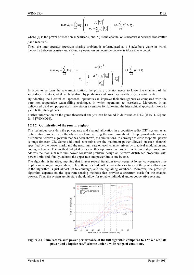
2.2.3.2 Optimisation of the sum throughput This technique considers the power, rate and channel allocation in a cognitive radio (CR) system as an optimization problem with the objective of maximizing the sum throughput. The proposed solution is a distributed iterative algorithm that has been shown, via simulations, to converge to close tooptimal power settings for each CR. Some additional constraints are the maximum power allowed on each channel, specified by the power mask, and the maximum rate on each channel, given by practical modulation and coding schemes. The method adopted to solve this optimization problem is a three step procedure: address the max sum-rate sum-power constraint problem, design an iterative distributed procedure with power limits and, finally, address the upper rate and power limits one by one. The algorithm is iterative, implying that it takes several iterations to converge. A longer convergence time implies more signalling overhead. Thus, there is a trade off between the exactness of the power allocation, if the algorithm is just almost let to converge, and the signalling overhead. Moreover, the presented algorithm depends on the spectrum sensing methods that provide a spectrum mask for the channel powers. Thus, the system architecture should allow for reliable individual and/or cooperative sensing.
-30 -25 -20 -15 -10 -5 0 5 10 150
0.5
1
1.5
2
2.5
Mean SNR at the (closest) cellborder [dB]
Mea
n ch
anne
l cap
acity
per
use
r [b/
Hz/
s]
Algorithm, with constraintsAlgorithm
+ EPAR, with constraints+ EPAR
α=2.6
α=3.6
Rat
e pe
r lin
k [b
/Hz/
s]
Figure 2-1: Sum rate vs. sum power performance of the full algorithm compared to a “fixed (equal) power and adaptive rate” scheme under a wide range of conditions.

WINNER+ D1.9
Version: 1.0 Page 20 (191)
The proposed algorithm was compared with the “equal power adaptive rate” [Lar07] algorithm, which is outperformed, as seen in Figure 2-1. This implies that the proposed algorithm is more efficient in using the transmitted power than the more conventional algorithm. A more detailed description of the proposed technique can be found in D1.6 [WIN+D16].
2.2.4 Traffic Identification and Load Management In order to guarantee an end to end QoS there is a common need for all scheduling techniques to know what the main requirements of traffic flow are. Furthermore, a non-uniform distribution of traffic between network nodes has very bad impact on network performance and affects the performance resource allocation process. Thus, three techniques have been proposed, which deal with the problem of traffic identification and load distribution. These include: automatic traffic characterisation, recursive nonlinear traffic prediction and dynamic load management and congestion control.
2.2.4.1 Automatic traffic characterisation LTE will support service differentiation with different QoS requirements using different Evolved Packet Core (EPC) bearers. Service will be mapped into bearers, and will allow differentiation in the RRM level. The proposed traffic classification approach serves as a complement and enriches the service differentiation process of LTE and future WINNER+ system. It is mandatory to have an entity responsible for analysing the traffic sent or received by the user. Although in the EPC description made by 3GPP in Release 8 the IP router of the network has the capability of analysing the data flow payload, a new entity, called the Packet Sniffer Point (PSP), is introduced in the system, as shown in Figure 2-2. The PSP needs to know the exact type of traffic of each data flow, and have full access to the Packet Data Network GateWay (PDN-GW).
Figure 2-2: New entity introduced in the EPC.
The introduction of new entity slightly modifies the Session Initiation Protocol/Service Description Protocol (SIP/SDP) followed in the IMS architecture. The Policy Decision Function (PDF) must emulate the SIP invite procedure in the IMS system to allow service activation. After classifying the data flow the PDF should carry out a reconfiguration of the IMS session and EPC bearer characteristics to adapt the current QoS to the real needs of the end user. In order to validate this new proposal some real traffic traces collected in a laptop have been used for training and testing a set of conventional classifiers. The accuracy of the Linear Discriminant Classifier (LDC), the Quadratic Discriminant Classifier (QUADRC) and the PCA-KNNC, which is the k Nearest Neighbour Classifier (KNNC with Principal Component Analysis (PCA) algorithm, has been evaluated. As expected, the larger the number of packets, the higher the efficiency of the classifier. However, there is a trade-off between the accuracy of the decision and the lack of QoS originated by the possible erroneous initial allocation. Thus, a range for the number of packets for 100 to 1000 is recommended. More information on this technique and the performance results can be found in D1.1 [WIN+D11] and D4.1 [WIN+D41].
2.2.4.2 Recursive nonlinear traffic prediction for dynamic resource allocation Efficient QoS scheduling algorithms require efficient prediction methods, which determine, for example, the user data rate, the congestion level information, and the traffic source rate. Hence, a new scheme is proposed, that is based on an efficient recursive estimation of neural networks weights, for adapting

WINNER+ D1.9
Version: 1.0 Page 21 (191)
network output to current conditions. The proposed adaptive neural network architecture simulates a Recursive implementation of a Non-linear Auto Regressive model (RNAR), which is suitable for complex and non-stationary processes. We assume that a Non-linear Auto Regressive model of order cp , denoted as NAR(pc) is used for estimate )(nxc as ( ) ( ( 1), ( 2),..., ( )) ( ), , , c c c c c c cx n g x n x n x n p e n c I P B= − − − + ∈ ,
where ( )cg ⋅ is a non-linear function, and ( )ce n an independent and identically distributed (i.i.d.) error with mean value of cμ and standard deviation of cb . The function ( )g ⋅ is actually unknown, however, a feed-forward neural network, with a Tapped Delay Line (TDL) filter as input, is able to implement a NAR model, within any acceptable accuracy. The main problem of implementing such a structure is the computational complexity of the process used to train the network. Thus, a novel training mechanism has been proposed, which is very computational efficient. Further information on the proposed technique can be found in D1.1 [WIN+D11].
2.2.4.3 Dynamic load management and congestion control The dynamic load management and congestion control aims to uniformly distribute the telecommunication traffic across the nodes of a mobile infrastructure network. The main idea of the load balancing is to apply appropriate values to the cell reselection offset parameters of a congested eNodeB. In this way, we can control and, more specifically, decrease the service area of a congested cell among its neighbours with the cell load as the only criterion either on uplink or on downlink direction. In order to achieve the dynamic alteration of the serving areas of the eNodesB, we have to find out a method to control the cell reselection mechanism. The cell reselection mechanism performs the selection of the serving base station based on the Reference Signal Received Power (RSCP) or the quality of the Reference Signals (RS) measured by the UT. The QrxlevminOffset parameter is used in LTE when a cell is evaluated for cell selection as a result of a periodic search for a higher priority eNodeB. Thus, this parameter can be utilized for the dynamic load balancing by controlling the size of the service area. Particularly, by increasing the value of the QrxlevminOffset, we correspondingly decrease the service area of the cell. To perform the load balancing, each eNodeB should have a functionality to identify the current telecommunication traffic and determine the biggest number of users or the corresponding traffic load. Moreover, some additional functionality has to be supported in order to have a correlation of the CQI with the offset values. On the other hand if we have large scale congestion scenario, areas in which the UTs could not be served by the network shall be formed. The proposed load balancing technique was evaluated by a radio-planning simulator called “ASTRIX” from Teleplan, where the impact of altering the cell-reselection offsets at the populated NodeB has been investigated. The alteration of the QrxlevminOffset parameter resulted in decrease of cell size and balancing the load between neighbouring sectors. More detailed description can be found in D1.1 [WIN+D11] and D4.1 [WIN+D41].
2.2.5 Efficient MBMS transmission MBMS has been specified as a part of LTE standard, where three emission modes can be considered: broadcast, multicast and unicast. Multicast delivery can be implemented through only p-t-p transmissions, a single p-t-m transmission with MBMS, or using both jointly in a hybrid approach by employing p-t-p transmission for error repair of the MBMS p-t-m transmission. Each of the considered modes provides different tradeoff between transmission time and amount of resources used, which can be represented by the transmitted energy. Multicast delivery with multiple p-t-p LTE simultaneous connections yields a transmission energy directly proportional to the number of active users. On the other hand, when considering the p-t-m transmission there is an optimum power value at low powers that minimizes the energy for a given data rate. Finally, the hybrid approach combines the advantages of both modes. In the investigated scenario, for a large enough number of users, there is a potential energy reduction that can be achieved using LTE-MBMS and LTE jointly, which increases to the point where the highest energy reduction with the hybrid delivery is achieved (about 30% energy reduction in the investigated case), as shown in Figure 2-3. Hence, the hybrid delivery is potentially the most efficient configuration. A file download service in LTE-MBMS has been proposed, consisting of the following three phases:
1. Service advertisement phase; in which the service is announced and set-up by the network and the users discover the service.
2. Initial LTE-MBMS file transmission phase. 3. Post-delivery repair phase to repair erroneous received files after initial MBMS transmission.

WINNER+ D1.9
Version: 1.0 Page 22 (191)
The decision of switching from p-t-p to p-t-m repair transmission is taken once a representative number of error reporting messages have been collected. Once the p-t-m repair session is completed, a new p-t-p repair session may be initiated if needed. To provide the post-delivery repair services users must report transmission failures in the uplink. When hybrid transmission is used, all users must report this error and therefore signalling may increase. However, efficient signalling methods are envisaged to include NACK packets within other feedback processes. Currently, two alternatives for MBMS inclusion are considered: time division multiplexing (TDM) of unicast transmission and multicast transmission, and separation of both transmission modes in different carriers, applying frequency division multiplexing (FDM). The investigation on advantages/disadvantages of both multiplexing schemes and the performance analysis is given in Appendix A.3. More detailed and extended description of the analysis can be found in D1.5 [WIN+D15].
0 20 40 60 80 1000
10
20
30
40
50
60
70
80
Number de Users
Ene
rgy
(J)
Multicast-Unicast HybridLTE-MBMSLTE p-t-p
Figure 2-3: Energy with the joint multicast-unicast transmission.
2.3 Potential Impacts on Signalling All the described scheduling and spectrum allocation techniques require an accurate prediction of channel state that is expected to be acquired through the usage of CQI reports, or taking advantage of system reciprocity in TDD mode. Besides, the scheduling information must be known by both transmitter and receiver in order to synchronise the transmission. Furthermore, for QoS scheduling, the information on traffic characteristics and QoS requirements has to be provided. Another issue is the availability of accurate CSI, which is necessary to perform the coordinated MIMO scheduling. The CSI is available when TDD mode is employed thanks to the channel reciprocity. However, in FDD mode an efficient signalling method is required. Finally, network synchronization in time and frequency is necessary to perform the inter-cellular coordination. Hence, the following aspects must be taken into account in the signalling design: − Efficient Channel Quality Indication (CQI reports): while a complete CQI knowledge at the
receiver is desirable and the knowledge should be as complete as possible at the transmitter − Efficient CSI. With imperfect channel knowledge, a performance decrease of resource allocation is
expected. − Efficient UL Resource Requests: signalling of uplink traffic demand is necessary for the UL
resource schedulers to decide. − Efficient DL and UL scheduler decision notifications: the scheduling result must be notified, so
that the receiver knows on which subchannel to listen for its packets and which physical mode to assume there. This signalling needs to be optimised to minimise the overhead.
− Traffic characteristics and QoS requirements signalling, which can be effectively realized using the flow mechanism proposed in section 8.2.4.
− Low-latency signalling link between the eNodeBs, and potentially the cluster controller. − Synchronization signalling, to achieve the network synchronization in time and frequency.
2.4 Potential Impacts on Architecture Most of the proposed techniques consider the OFDMA-based system, with both TDD and FDD modes available. Moreover, for the analysis of the MIMO coordinated resource allocation the capability of using and coordinating multiple transmitters is assumed. Hence the system architecture encompasses just a set

WINNER+ D1.9
Version: 1.0 Page 23 (191)
of base stations (or eNodeB’s, according to the 3GPP nomenclature) and a gateway node that connects the system with other IP-based networks. Few slight modifications of this flat architecture are proposed to provide the means of data interchange among base stations. Furthermore, the CoMP scheduling technique proposes to add some kind of cluster controller to collect common information and make joint decisions. Another issue is that the system architecture should allow for reliable individual and/or cooperative spectrum sensing to enable the optimization of joint power, rate and channel allocation. Slightly different system model is assumed when analyzing the automatic traffic characterization, as the specific the EPC description made by 3GPP in Release 8 is considered. An introduction of a new entity, the PSP (Packet Sniffer Point), is proposed, and a new interface must be defined to connect this entity with the PCRF (Policy and Charging Rules Function).
2.5 Compatibility with LTE and LTE-Advanced Most of the proposed techniques are fully compatible with both LTE and LTE-Advanced [3GPP36300, 3GPP36912]. As the QoS provisioning through scheduling is already a part of LTE standard, the proposed techniques fulfil the LTE requirements. Moreover, the spectrum allocation techniques were developed on the basis of LTE system and require no changes in the specification. As for the traffic identification and load balancing, only the automatic traffic characterization require changes in current system architecture proposed in LTE and LTE-Advanced, thus is not fully compatible. When considering the coordinated MIMO resource allocation, this topic is not covered in the LTE specification. All of the proposed techniques require some changes in either the architecture or protocol structure. The low complexity resource allocation in MU SDMA and CoMP scheduling assume a presence of a central controller, which coordinates the BSs in the network or coordination cluster (depending on the coordination level). On the other hand, the decentralised interference avoidance using busy bursts requires changes in current protocol structure, by introducing the “piggybacked” busy burst symbols.
2.6 Conclusions Resource allocation is a key factor influencing the system performance. An efficient and flexible scheduling and spectrum allocation process improves the achieved spectral efficiency. Moreover, the QoS support allows providing heterogeneous services in the network, such as the VoIP, streaming video, etc. Thus, twelve techniques have been proposed, which constitute five areas of investigation: the QoS scheduling, coordinated MIMO scheduling, spectrum allocation techniques, traffic identification and load balancing, and MBMS provisioning. All techniques were developed as proposals for the LTE or LTE-Advanced systems, to which they are mostly compatible. Several minor changes in the existing signalling specification and architecture are proposed to be able to employ the described innovations. Table 2-2 summarizes the techniques proposed in WINNER+ concerning resource allocation.
Table 2-2: Summary of resource allocation techniques.
Applicable to FDD/TDD
Applicable to UL/DL
Expected performance (+ source)
Compatibility to LTE/ Topic for future studies
Traffic-aware score-based scheduling
Both TDD and FDD DL, possible in UL if traffic signalling is available
QoS support (D1.1) Compatible to LTE
QoS scheduler based on utility prediction
Both TDD and FDD DL and UL
QoS support, minimal gain in throughput over PF (D1.1 and D4.1)
Compatible to LTE
Closed loop control MAC Both TDD and FDD DL and UL
Scheduling operations divided into several tasks (A.1)
Compatible to LTE
Low complexity resource allocation in MU SDMA
Both TDD and FDD DL and UL
Gain in throughput through interference avoidance (D1.4)
Compatible to LTE-Advanced
Interference mitigation based on efficient scheduling
Both TDD and FDD DL
Gain in throughput - over 40% comparing to PF (D1.5)
For future studies
Decentralised interference avoidance using busy
TDD DL
13% increase in median system throughput (D1.5)
For future studies

WINNER+ D1.9
Version: 1.0 Page 24 (191)
bursts Heuristic Busy Burst Thresholding Applied to Interference Aware Beam Selection
TDD DL
Improvement of user throughput when heuristic thresholding is applied (A.2)
For future studies
Spectrum sharing from a game theory perspective
Both TDD and FDD DL and UL
Operator throughput improvement (D1.6)
Compatible to LTE-Advanced
Optimisation of the sum throughput
Both TDD and FDD DL and UL
Near optimal power allocation and a high total system rate (D1.6)
Compatible to LTE
Automatic traffic characterisation
Both TDD and FDD DL and UL
Traffic classification based on 100 to 1000 collected packets (D1.1 and D4.1)
For future studies
Recursive nonlinear traffic prediction for dynamic resource allocation
Both TDD and FDD DL and UL
Traffic prediction (D1.1) Compatible to LTE
Dynamic load management and congestion control
Both TDD and FDD DL and UL
Load balancing between nodes (D1.1)
Compatible to LTE
Multicast and broadcast repair services
Both TDD and FDD DL
Better utilization of resources (D1.5)
Compatible to LTE-Advanced

WINNER+ D1.9
Version: 1.0 Page 25 (191)
3. Carrier Aggregation
3.1 Introduction
3.1.1 Basic Concepts There are some concepts defined in the ITU-R under the idea of carrier aggregation that must be clarified to understand the main research challenges addressed in WINNER+ and their constraints:
Carrier Aggregation: To transmit data on multiple carriers, or sub-bands, contiguous or non-contiguously located by using several parallel RF transceivers and Base Band (BB) processing creating a virtual single large FFT. UT may adopt a single wideband-capable RF front end (i.e., mixer, AGC, ADC) and a single FFT, or multiple “legacy” RF front ends (<20 MHz) and FFT engines. The choice between single or multiple transceivers depends on power consumption, cost, size, and flexibility to support other aggregation types. At the end, larger bandwidth than 20MHz can be supported using carrier aggregation.
Component Carrier: The independent RF band, or carrier, for transmitting IMT Advanced signal which is aggregated with other sub-bands to conform a larger bandwidth. Each component carrier shall maintain its original structure to support single-carrier-capable users, even it is aggregated to a larger bandwidth.
Guard Band: the guard subcarriers that cannot be used for transmission. In case of contiguous carrier aggregation this guard band is located at the edge of the aggregated bandwidth. If non-contiguous aggregation, each sub-band will have its own guard-bands, thus reducing efficiency.
Centre frequency of the aggregated bandwidth: The centre of the total aggregated bandwidth. Centre frequency of the component carrier: The centre frequency of each component carrier.
3.1.2 ITU-R Requirements and Implementation in Standards According to the ITU-R requirement for IMT Advanced [M.2134], the minimum aggregated bandwidth shall be 40MHz, although the extension to larger bandwidth (up to 100MHz) is encouraged. In the description of the 3GPP candidate for IMT Advanced – i.e. LTE-Advanced – the following deployment scenarios are indicated [3GPP36912]:
Table 3-1: Deployment scenarios [3GPP36912].
Proposed initial deployment scenario for investigation Single band contiguous allocation for FDD (UL:40 MHz, DL: 80 MHz)
Single band contiguous allocation for TDD (100 MHz) Multi band non-contiguous allocation for FDD (UL:40MHz, DL:40 MHz)
Multi band non contiguous allocation for TDD (90 MHz) On the other hand, IEEE has not clearly stated in the IMT Advanced candidate proposal which are their choices for carrier aggregation. Only the following text can be found in [IEEE80216m] concerning the IEEE 802.16m requirement of the operating bandwidth: “[...] a common MAC entity to control a PHY spanning over multiple frequency channels. The channels may be of different bandwidths (e.g. 5, 10 and 20 MHz) on contiguous or non-contiguous frequency bands. The channels may be of the same or different duplexing modes, e.g. FDD, TDD, or a mix of bidirectional and broadcast only carriers [...]” From the ITU-R requirements on maximum bit rate and peak efficiency, the minimum requirement for the aggregated bandwidth can be derived: 1Gbps/15bps/Hz = 66.66MHz. Therefore, bandwidth larger than 67MHz (e.g.: 70, 80, 90, 100 MHz) must be implicitly considered, unless the peak spectral efficiency is higher than 15 bps/Hz.
3.1.3 Hardware and Legal Limitations Due to hardware limitations in the point of terminal complexity, no more than 8192 FFT (213) will be implemented by vendors. Considering LTE sub-carrier spacing this results in more than 120MHz whereas for IEEE 802.16m with component carriers of 10MHz this maximum bandwidth is reduced down to 80MHz. All other bands can be received by removing the additional band after receiving the signal of full bandwidth, although this method has problems of loss of SNR for large bandwidth. Another approach is to use multiple RF transceivers. In this case, though the guard bands of each component carrier cannot be utilized, the above-mentioned loss is minimized. Moreover, it requires additional complexity but the combination of over-sampling for FFT and rate-conversion filter can be also considered.
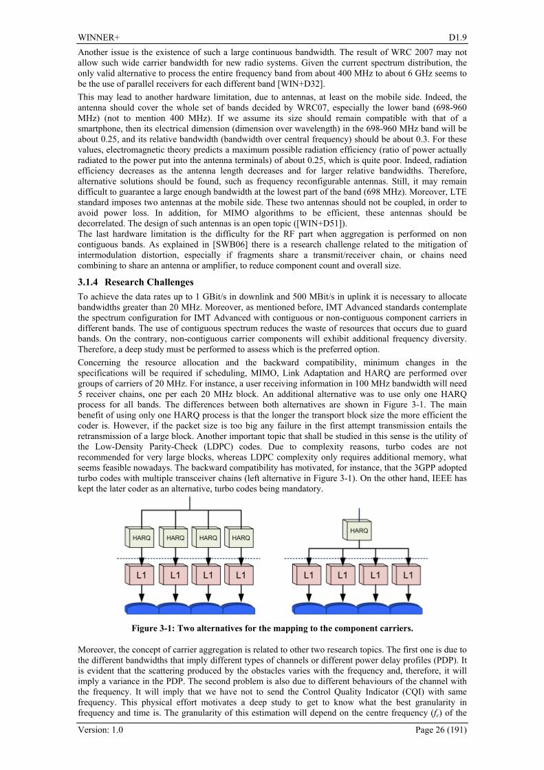
WINNER+ D1.9
Version: 1.0 Page 26 (191)
Another issue is the existence of such a large continuous bandwidth. The result of WRC 2007 may not allow such wide carrier bandwidth for new radio systems. Given the current spectrum distribution, the only valid alternative to process the entire frequency band from about 400 MHz to about 6 GHz seems to be the use of parallel receivers for each different band [WIN+D32]. This may lead to another hardware limitation, due to antennas, at least on the mobile side. Indeed, the antenna should cover the whole set of bands decided by WRC07, especially the lower band (698-960 MHz) (not to mention 400 MHz). If we assume its size should remain compatible with that of a smartphone, then its electrical dimension (dimension over wavelength) in the 698-960 MHz band will be about 0.25, and its relative bandwidth (bandwidth over central frequency) should be about 0.3. For these values, electromagnetic theory predicts a maximum possible radiation efficiency (ratio of power actually radiated to the power put into the antenna terminals) of about 0.25, which is quite poor. Indeed, radiation efficiency decreases as the antenna length decreases and for larger relative bandwidths. Therefore, alternative solutions should be found, such as frequency reconfigurable antennas. Still, it may remain difficult to guarantee a large enough bandwidth at the lowest part of the band (698 MHz). Moreover, LTE standard imposes two antennas at the mobile side. These two antennas should not be coupled, in order to avoid power loss. In addition, for MIMO algorithms to be efficient, these antennas should be decorrelated. The design of such antennas is an open topic ([WIN+D51]). The last hardware limitation is the difficulty for the RF part when aggregation is performed on non contiguous bands. As explained in [SWB06] there is a research challenge related to the mitigation of intermodulation distortion, especially if fragments share a transmit/receiver chain, or chains need combining to share an antenna or amplifier, to reduce component count and overall size.
3.1.4 Research Challenges To achieve the data rates up to 1 GBit/s in downlink and 500 MBit/s in uplink it is necessary to allocate bandwidths greater than 20 MHz. Moreover, as mentioned before, IMT Advanced standards contemplate the spectrum configuration for IMT Advanced with contiguous or non-contiguous component carriers in different bands. The use of contiguous spectrum reduces the waste of resources that occurs due to guard bands. On the contrary, non-contiguous carrier components will exhibit additional frequency diversity. Therefore, a deep study must be performed to assess which is the preferred option. Concerning the resource allocation and the backward compatibility, minimum changes in the specifications will be required if scheduling, MIMO, Link Adaptation and HARQ are performed over groups of carriers of 20 MHz. For instance, a user receiving information in 100 MHz bandwidth will need 5 receiver chains, one per each 20 MHz block. An additional alternative was to use only one HARQ process for all bands. The differences between both alternatives are shown in Figure 3-1. The main benefit of using only one HARQ process is that the longer the transport block size the more efficient the coder is. However, if the packet size is too big any failure in the first attempt transmission entails the retransmission of a large block. Another important topic that shall be studied in this sense is the utility of the Low-Density Parity-Check (LDPC) codes. Due to complexity reasons, turbo codes are not recommended for very large blocks, whereas LDPC complexity only requires additional memory, what seems feasible nowadays. The backward compatibility has motivated, for instance, that the 3GPP adopted turbo codes with multiple transceiver chains (left alternative in Figure 3-1). On the other hand, IEEE has kept the later coder as an alternative, turbo codes being mandatory.
Figure 3-1: Two alternatives for the mapping to the component carriers.
Moreover, the concept of carrier aggregation is related to other two research topics. The first one is due to the different bandwidths that imply different types of channels or different power delay profiles (PDP). It is evident that the scattering produced by the obstacles varies with the frequency and, therefore, it will imply a variance in the PDP. The second problem is also due to different behaviours of the channel with the frequency. It will imply that we have not to send the Control Quality Indicator (CQI) with same frequency. This physical effort motivates a deep study to get to know what the best granularity in frequency and time is. The granularity of this estimation will depend on the centre frequency (fc) of the
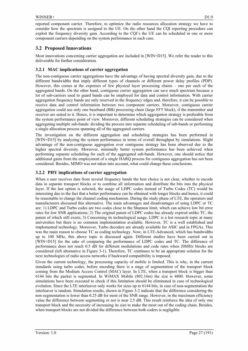
WINNER+ D1.9
Version: 1.0 Page 27 (191)
reported component carrier. Therefore, to optimize the radio resources allocation strategy we have to consider how the spectrum is assigned to the UE. On the other hand the CQI reporting procedure can exploit the frequency diversity gain. According to the CQI’s the UE can be scheduled in one or more component carriers depending on the system performance in each case.
3.2 Proposed Innovations Most innovations concerning carrier aggregation are included in [WIN+D15]. We refer the reader to this deliverable for further consideration.
3.2.1 MAC implications of carrier aggregation The non-contiguous carrier aggregations have the advantage of having spectral diversity gain, due to the different bandwidths that imply different types of channels or different power delay profiles (PDP). However, this comes at the expenses of few physical layer processing chains – one per each of the aggregated bands. On the other hand, contiguous carrier aggregation can save much spectrum because a lot of sub-carriers used to guard bands can be employed for data and control information. With carrier aggregation frequency bands are only reserved in the frequency edges and, therefore, it can be possible to receive data and control information between two component carriers. Moreover, contiguous carrier aggregation could use only one baseband (BB) processing chain (large FFT block), if the transmitter and receiver are suited to it. Hence, it is important to determine which aggregation strategy is preferable from the system performance point of view. Moreover, different scheduling strategies can be considered when aggregating multiple sub-bands: dividing the process into separate scheduling of sub-bands or performing a single allocation process spanning all of the aggregated carriers. The investigation on the different aggregation and scheduling strategies has been performed in [WIN+D15] by analyzing the system performance in terms of overall throughput by simulations. Slight advantage of the non-contiguous aggregation over contiguous strategy has been observed due to the higher spectral diversity. Moreover, minimally better system performance has been achieved when performing separate scheduling for each of the aggregated sub-bands. However, one should notice that additional gains from the employment of a single HARQ process for contiguous aggregation has not been considered. Besides, MIMO was not taken into account, what could change these conclusions.
3.2.2 PHY implications of carrier aggregation When a user receives data from several frequency bands the best choice is not clear, whether to encode data in separate transport blocks or to combine all information and distribute the bits into the physical layer. If the last option is selected, the usage of LDPC codes instead of Turbo Codes (TC) would be interesting due to the fact that a better performance can be obtained with longer blocks and hence, it could be reasonable to change the channel coding mechanism. During the study phase of LTE, the operators and manufacturers discussed this alternative. The main advantages and disadvantages of using LDPC or TC are: 1) LDPC and Turbo codes are two codes close to the Shannon limit, which can achieve low bit error rates for low SNR applications; 2) The original patent of LDPC codes has already expired unlike TC, the patent of which still exists; 3) Concerning its technological usage, LDPC is a hot research topic at many universities but there is no common implementation available. However, TC is a well established and implemented technology. Moreover, Turbo decoders are already available for ASIC and in FPGAs. This was the main reason to choose TC as coding technology. Now, in LTE-Advanced, which has bandwidths up to 100 MHz, this above topic is discussed again. Different studies have been carried out in [WIN+D15] for the sake of comparing the performance of LDPC codes and TC. The difference of performance does not reach 0.5 dB for different modulations and code rates when 20MHz blocks are considered (left alternative in Figure 3-1). Therefore, TC continues to be an appropriate solution for the next technologies of radio access networks if backward compatibility is imposed. Given the current technology, the processing capacity of mobile is limited. This is why, in the current standards using turbo codes, before encoding there is a stage of segmentation of the transport block coming from the Medium Access Control (MAC) layer. In LTE, when a transport block is bigger than 6144 bits the packet is segmented. In WiMAX Mobile (802.16m) the size is 4800. However, some simulations have been executed to check if this limitation should be eliminated in case of technological evolution. Since the LTE interleaver only works for sizes up to 6144 bits, in case of non-segmentation the interleaver is random. Simulation results, shown in Figure 3-2 indicate that the difference considering the non-segmentation is lower than 0.25 dB for most of the SNR range. However, in the maximum efficiency value the difference between segmenting or not is near 2.5 dB. This result reinforce the idea of only one transport block and the necessity of increasing its size to make the most out of the coding chain. Besides, when transport blocks are not divided the difference between both coders is negligible.

WINNER+ D1.9
Version: 1.0 Page 28 (191)
5 6 7 8 9
5
10
15
20
SNR (dB)
Effe
ctiv
e T
hrou
ghpu
t (M
bps)
Standard TCOne Block LDPCOne Block TC
Figure 3-2: Performance comparison between turbo codes with packets no larger than 6144, turbo codes with only one turbo block and LDPC codes for [126476 bits, rate=5/6] and a QPSK modulation.
3.2.3 CQI signalling in Carrier Aggregation OFDMA systems such as LTE and LTE-Advanced can perform link adaptation and user multiplexing in the frequency domain if the packet scheduler in the eNodeB has the knowledge of the instantaneous channel quality. Frequency selective scheduling (FSS) significantly improves system performance. Depending on the CQI bandwidth used, explicit CQI feedback for every Resource Block (RB) can result in significant overhead and therefore reduced capacity. In case of reducing excessively the CQI bandwidth the FSS performance benefit could result degraded. An efficient and flexible technique for the CQI reporting would optimize the trade-off between the system performance of a frequency selective scheduling algorithm and the uplink bandwidth occupancy. Therefore, it could be useful to define a flexible CQI reporting method to select a certain level of granularity in the time domain and in the frequency domain depending on the radio channel condition the UE experiences. A preliminary analysis of this proposal was performed using a dynamic system level simulator that follows the indications of ITU-R. The aim is to identify, for a set of different scenarios, the optimum CQI reporting period and the number of RBs included per report. From the obtained results it can be concluded that all scenarios augmenting the reporting period provoke a significant degradation on spectral efficiency. This degradation is more or less significant depending on the specific scenario. However, the reporting bandwidth does not affect all cases in the same way. For the urban case (macrocellular, UMa, and microcellular UMi), a lower reporting period increases the spectral efficiency, since errors on channel estimation are minimised. On the contrary, for the rural case (RMa) the differences among reporting bandwidths are not significant. These preliminary results have been summarized in Figure 3-3, taking into account only the best results in terms of cell performance in order to find the optimal trade-off between the maximization of the cell efficiency and the minimization of the uplink overhead. Based on these results, and assuming the definition of an acceptable degradation in terms of system performance, it could be identified the optimal pair (number of TTI - number of RBs) that could be the optimal trade-off considering each scenario.

WINNER+ D1.9
Version: 1.0 Page 29 (191)
101 102 103 104 105 1060
0.5
1
1.5
2
2.5
Uplink control rate [b/s]
Cel
l spe
ctra
l effi
cien
cy [b
/s/H
z]
128-5064-50
32-5016-50 8-50
4-50
16-1016-5 8-5 16-2
4-52-5 1-5 2-2 1-2 1-1
128-50
64-50
32-5016-50 8-50
8-2516-10
8-108-5 4-5 2-5 2-1 1-1
128-5064-50
32-5016-50 8-50 4-50 2-50 2-25 2-1 1-1
UMaUMiRMa
Figure 3-3: Cell spectral efficiency vs uplink overhead for Urban Macro (UMa), Urban Micro (UMi) and Rural Macro (RMa) scenarios. Each pair of numbers represents the reporting period
and reporting bandwidth respectively.
3.3 Potential Impacts on Signalling and Architecture When using carrier aggregation, some signalling information related to the allocation of the resources shall be provided. As previously mentioned, the 3GPP is currently addressing this specific topic where the following constraints are being considered: the backward compatibility and the reduction of the complexity. However, with the objective of having the maximum system performance, all cases must be studied. The CQI analysis has confirmed that some significant overhead reduction can be achieved if the carrier and environment are known. Therefore flexibility in the reporting mechanism is recommended. The mentioned CQI reporting procedure can be automatically performed by the UE depending on the frequency carrier that this UE is using to communicate with the base station and depending on the speed that characterizes its radio channel. Therefore, in this case no specific requirement on signalling nor specific measurement would be expected by the eNodeB and by the UE in order to perform such a procedure. Nevertheless, assuming that the eNodeB has the possibility to know the look-up table used by the UE and/or assuming that the eNodeB has the possibility to set its own look-up table in the UE, the eNodeB could decide to force the UE to change the granularity of the CQI reporting referring to another pair (number of frequencies, number of TTIs) contained in the look-up table in order to optimize its radio resources allocation strategy. In such scenario, it is expected a new signalling from the UE to the eNodeB where the UE communicates the look-up table to the base station every time that the UE is going to camp on a new cell or it is expected a new signalling from the eNodeB to the UE where the eNodeB communicates its own look-up table every time that a new UE is going to be served. Moreover in this scenario it is expected a new signalling from the eNodeB to the UE where the eNodeB communicates the UE to change the level of CQI reporting granularity to be used every time that the eNodeB wants to force the UE to use a new combination (number of frequencies, number of TTIs) of the look-up table.
3.4 Potential Impacts on Architecture and Protocols We can have either segmentation at the MAC layer or segmentation at the physical layer. Depending on the selected scheme the protocol stack shall be modified with respect to LTE. In Figure 3-1 two schemes of resource mapping were presented. On the right the MAC layer does not segment the packets and the physical layer is the entity in charge of distributing bits among resource elements. In this case, if a packet arrived with errors all the Transport Blocks (TBs) should be retransmitted and, therefore, it is not very efficient. On the left hand, if a packet arrived with errors only the packet associated with the TB segmented in the MAC layer must be retransmitted. According to last discussions in standardisation forums, the protocol stack will not be modified in this sense.

WINNER+ D1.9
Version: 1.0 Page 30 (191)
Concerning MAC aspects, the only requirement in carrier aggregation is the synchronization of all of the aggregated carriers, with respect to both time and frequency.
3.5 Compatibility to LTE and LTE-Advanced Unless the use of LDPC codes, the rest of proposals have been developed with the main scope of keeping backward compatibility.
3.6 Conclusions Carrier aggregation is one of the main factors of the success of the next 4G technologies. This concept implies transmitting data on multiple contiguous or non-contiguous sub-bands, called component carriers. Each component carrier shall occupy up to 20 MHz of bandwidth in which it can be transmitted information towards legacy or IMT Advanced mobiles, thus guaranteeing backward compatibility. In [WIN+D15] the concept of carrier aggregation has been deeply assessed from different points of view; specifically from physical layer, MAC layer and signalling. Three techniques were proposed:
1. Spectrum aggregation from the physical layer perspective: this research focuses on the viability of using LDPC codes with longer size blocks. As a conclusion of this study, transport block segmentation should be avoided as much as possible, since it naturally entails some degradation in the system performance. The improvement achieved with LDPC is, in most cases, limited to 0.5 dB. Provided that LDPC are not LTE-compatible, its inclusion in WINNER+ seems not justified.
2. Spectrum aggregation from the scheduling perspective: the research focuses on different aggregation strategies and related scheduling approaches. A significant advantage of non-contiguous carrier aggregation over contiguous aggregation has been observed, mostly due to the higher spectral diversity of the former strategy. The disadvantage regards hardware redundancy, i.e. the employment of more than one physical (and possibly MAC) layer processing chains. Carrier aggregation is a must in IMT Advanced and hence a proper allocation of frequencies is recommended in order to make the most of the diversity gain offered by the wide bandwidth.
3. CQI signalling in Carrier Aggregation: from the point of view of the CQI reporting procedure in a bandwidth aggregation scenario, the proposed concept defines the CQI report granularity in the time domain and in the frequency domain depending on the carrier the UE is using aiming to save uplink bandwidth without degrading the system performance.
According to ITU-R requirements carrier aggregation must be included in the WINNER+ system concept and this is why WINNER+ consortium has dedicated spetial effort to its study. This section summarises the contributions from the radio resource management point of view, whereas other aspects are addressed in section 3 of [WIN+D33]. Finally, Table 3-2 summarizes the main interest of the three techniques proposed in the WP1 of WINNER+ concerning carrier aggregation.
Table 3-2: Summary of carrier aggregation techniques.
Applicable to
FDD/TDD Applicable to UL/DL
Expected performance (+ source)
Compatibility to LTE/LTE-A
Topic for future studies
MAC Implications of Carrier Aggregation ALL
Up to 25% increase in system throughput
[WIN+D15] LTE-A
PHY Implications of Carrier Aggregation ALL
Max 0.5dB TC vs LDPC Up to 2.5 dB for non-
segmentation [WIN+D15]
LTE-A and LDPC for Future Studies
CQI signalling in Carrier Aggregation FDD
25% - 50% Improvement in Spectral Efficiency
[WIN+D15] LTE-A

WINNER+ D1.9
Version: 1.0 Page 31 (191)
4. Femtocells
4.1 Introduction
4.1.1 General The best method to increase capacity in cellular networks is to bring transmitter and receiver closer to each other [Cha09]. Conventionally this can be accomplished in two basic ways: (1) increase eNB density; (2) deploy relay stations. Increasing the number of eNB’s is the most expensive solution. Relay stations are cheaper since only a subset of eNB functionality needs to be implemented.
Femtocells provide a third alternative. Femtocells are low-cost, low-power, short-range, plug-and-play base stations [CA08]. They are privately owned and typically installed in subscribers’ homes; backhaul is typically implemented by a DSL connection. Due to indoor deployment, there is natural isolation between femtocells resulting from the penetration loss. This provides efficient spatial reuse of resources.
In principle, we could use different bands for femto and macro operations. However, in order to maximize spectral efficiency, femto and macro layers share the spectrum. This approach has another advantage: it avoids bi-mode terminals.
Femtocells are divided into groups depending on the admission rights. Closed access refers to a femtocell, where access rights have been limited to a small group of UE’s (Closed subscriber group (CSG)). This is typically the case with privately owned femto base stations. Femtocells with open access allow all UE’s to connect to it. Third group uses mixed access: full access rights are given to a small subset of UE’s; limited access is given to all UE’s. For example, maximum throughput may be limited, or access is allowed only if UE’s in CSG do not use the femtocell.
The obvious problem with CSG’s is the macro-to-femto interference. Since a nearby macro UE cannot connect to the femto base station, it causes interference to the femtocell. Open subscriber group may partially solve this problem by allowing any UE to connect to the femtocell. An intermediate group exists which allows users outside the CSG limited connectivity. In addition, two other types of interference may arise, namely the femto-to-femto and femto-to-macro. The former occurs on both uplink Femto UE Home NodeB and downlink Home NodeB Femto UE among neighboring femtocells, whereas the latter occurs on both uplink (Femto UE eNB) and downlink (Home NodeB Macro UE).
The main advantage of femtocells is the ability to increase indoor coverage. This is especially important since majority of the traffic originates indoors, and penetration loss limits the throughput and coverage when the UE is connected to a macro eNB. Since there is no penetration loss between the UE and the femto BS, very low transmission powers can be used.
Femtocells also offload traffic from macro cells, potentially increasing the performance of both macro UE’s and femto UE’s. With wireless in-band relays, the offloading effect is smaller since resources are needed for the relay’s backhaul link. In general, femtocells also do not have the half duplex limitation of relays.
Since femtocells typically are installed and owned by the consumer, there are no costs for deployment, energy supply and site rental for the operator. This may result in smaller fees.
4.1.2 Femtocell Standardization Femtocell technology began to attract industry in 2007 and early 2008 [KYF09]. The need for femtocells came from the requirement of good indoor signal quality and interference limited nature of WCDMA networks. Although LTE network technology is different, femtocells still provide potentially very large gains in spectral efficiency per area. Existing fixed broadband technology as the backhaul leads to reduction in CAPEX and OPEX.
The Femto Forum started the discussion on the femto architecture in the beginning of 2008. In May 2008 a single architecture was agreed. It is based on a modified version of the existing Iu interface. The agreement has lead to the Iuh interface.
As mentioned above, the major challenge with femtocells is interference. Interference management techniques can be divided into two categories: interference avoidance, and interference coordination and interference suppression. In the next subsection we address these methods.

WINNER+ D1.9
Version: 1.0 Page 32 (191)
4.1.3 Interference Management Coping with interference is of fundamental importance with femtocells. The interference management techniques can be divided into three groups: interference avoidance, interference coordination and interference suppression.
In interference avoidance, the system is set up so that interference does not occur, or the probability of interference is small. This is typically done by reusing resources on different geographical locations.
Interference coordination can be divided into reactive and proactive schemes [HT09]. Reactive schemes are based on measurements. If the measured interference is too high, actions are taken to reduce the interference. Proactive schemes include transmission of scheduling information to the neighbor base stations, which can then take this information into account in their own scheduling.
Interference suppression [Web07] includes methods to specifically subtract interference from the received signal. Examples are interference rejection combining (IRC), multi-user MIMO, and time domain methods. The problem with suppression techniques is increased hardware complexity.
4.2 Proposed Innovations
4.2.1 Femtocells with beacons Femto base stations broadcast control information to monitor the spectrum usage situation locally. The UE’s receive beacons from several HNBs and when combined with information about the UE’s physical location, local awareness of the spectrum usage situation can be formed. This information is then sent back to the HNB. Combining these messages gives the HNB information about the spectrum usage situation in the entire cell area [WIN+D12].
The broadcast messages include information about neighbor cells, which resources the neighbors are using and how much interference the neighbors are causing. Optionally, information about bandwidth demand estimates and TDD UL/DL switching point is also broadcast.
Each HNB should estimate if the resources currently used by it are sufficient for the operation or not. If an HNB has more resources than it needs, the HNB should release some resources, and modify its own beacon information accordingly (i.e. announce that resources released are now free for other access points.)
If local awareness indicates that free resources are available, and access point needs more resources, it should reserve the resources by modifying the resource reservation information in beacon to include new resources.
Priority based fairness scheme is used to resolve resource usage conflicts between nearby femtocells. The method has to solve two problems: (1) How to decide which femtocell can use the resources in a fair manner; (2) How to indicate to the other femtocell(s) that the resource are reserved. Each femtocell is given a priority value, which is used to settle a conflict (a femtocell with higher priority can take resources from a femtocell with lower priority.) These priorities are broadcast by each femtocell, and nearby UE’s are able to receive this and transmit the information to their own femtocell.
4.2.2 Coordinated femtocells with ICIC This innovation introduces an interference coordination technique for femtocells. The most critical scenario from the interference point of view is a macro UE located in the vicinity of a femto cell. Despite the low transmission power in the femtocell, there may be detrimental interference between macro UE and HNB.
The cell area is divided into regions [WIN+D12]. Each cell-edge region is characterized by the corresponding neighbouring macroeNB (the one which is closest to the area). Each HNB uses RSRP (Reference Signal Received Power) measurements from FUEs to establish whether it lies in one of the cell-edge areas or not. If not, it is then classified into belonging to a cell-interior area (near the serving eNB). High interference indicator (HII) messages (specific to each region) are sent to all femtocells located in the region. The procedure is similar to the UL intercell interference coordination (ICIC) [TS36420, TS36423], and extended to DL.
When the macro UE (MUE) detects potential interference from a femtocell, it signals the femto ID to the eNB, which then uses the HII message to inform the femtocell about which physical resource block (PRB) it may schedule or not. The femtocell then decides how to assign resources to their FUEs, thus preventing them to use the same DL and UL physical resources. As a result, FUEs and MUEs that re-use the same resource blocks are inherently spatially separated.

WINNER+ D1.9
Version: 1.0 Page 33 (191)
An optimized signaling method, called Request and Release signaling was introduced in [WIN+D16]. The objective is to decrease the amount of signaling over the X2 interface.
4.2.3 Self organized femtocells This contribution is based on estimating the potential femto-to-macro interference (Annex B.1, [WIN+D12], [WIN+D16]). The femtocell uses TDD mode on the UL band of the macro network. The amount of the potential interference is estimated from the eNB → HNB path loss. If the path loss is large enough, we can be quite certain that the traffic in the femtocell does not interfere with the macro cell uplink.
Home UE’s (and HNB) measure the RSRP from the macro BS (eNB). These measurement results are sent to the HNB, which averages out fast fading by combining the measurement results to form a single path loss estimate. These calculations are performed for each macroBS. The minimum path loss is then compared to a threshold. If the minimum of eNB → HNB path losses is smaller than the threshold, the femtocell is simply switched off. This is not usually a problem, since the HUE’s may connect directly to the eNB. On the other hand, if the path loss is large, femtocell operation is allowed. Transmission powers of both HBN and HUE are limited (typically in the order of 10 dBm) and as a result, the interference to the macro network is minimal. Note also that often HNB and HUE are in the same premises and penetration loss does not limit the performance, and on the other hand has a shielding effect to isolate femtocells from each other and from the macrocell.
4.2.4 Femtocells and game theory This contribution (Annex B.2) is based on the use of game theoretic tools to model the scenario where eNB and HNB share the same spectrum. It is shown that there is an optimal number of HNB that can be deployed in a network, after which the overall efficiency of a network decreases. Moreover, through the concept of hierarchy it is shown that the performance of the network can be improved, bridging therefore the gap between the non-cooperative and centralized approach.
4.3 Expected Performance of Innovations With femtocell with beacons, coverage is significantly improved. In the simulated case the outage probability decreased from 15 % (without femtocells) to 0 % (with femtocells). Furthermore, the median data rate in the system increased by more than 200 %.
For coordinated femtocells with ICIC, the femto-to-macro interference power (received by the MUE) is decreased by 20 dB compared to the case without ICIC, illustrated in Figure 4-1(b). Self organized femtocells with open access provide 170 % throughput increase median cell throughput with 8 femtocells per macrocell. Gain in UE throughput is 390 %. For closed access, the gain in cell throughput (TP) is 146 % with 3 femtocells per macrocell, shown in Figure 4-1 (c). More results can be found in Annex B.1.
The application of Femtocells using game theory provides improvement in the sum-rate of the network when adopting the concept of hierarchy. Moreover, given a geographical area and number of users, there exist an optimal number of base stations to be deployed.
Examples of femtocell performance are given in Figure 4-1.
(a)
-140 -130 -120 -110 -100 -90 -80 -70 -60 -500
0.2
0.4
0.6
0.8
1
Interference Pow er (dBm)
Cum
ulat
ive
Den
sity
MacroFemto, conventionalFemto, proposed
(b)

WINNER+ D1.9
Version: 1.0 Page 34 (191)
0 5 10 15 20 25 30 35 40 45 50 550
0.1
0.2
0.3
0.4
0.5
0.6
0.7
0.8
0.9
1
Cell throughput (Mbit/s)
Pro
babi
lity
CDF of cell TP
Without femtocells3 femtocells / macrocell
(c)
0 5 10 15 20 250
2
4
6
8
10
12
σ2 = 1
number of access points
sum
-rate
of t
he n
etw
ork
Stackelberg
Selfish
Centralized
(d)
Figure 4-1. Femtocell performance. (a) Femtocells with beacons.
(b) Coordinated femtocells with ICIC. Interference power received by a MUE near a femtocell. (c) Self organized femtocells. System TP with closed access (three HNB’s per macrocell).
(d) Femtocells and game theory. Sum-rate for vs. number of access points.
4.4 Potential Impacts on Signalling and Measurements For femtocells with beacons, at least beacon information structure and UE feedback signalling have to be defined. The beacons should not be a problem since existing broadcast channel can be utilized.
The signalling impacts for coordinated femtocells are quite low since existing procedures for ICIC between macro cells can be extended.
In the case of self organized femtocells, the HUE’s have to measure the RSRP from the macro BS and estimate the path loss, and send the estimate to the HNB. Also some changes due to TDD on the UL band in the signalling and frame structure are needed.
With femtocells and game theory signalling between eNB and HNB is required. However, this can be done through the X2 interface between the macro and the femtocell in which case the macrocell reports to the femtocell that there is extensive interference at the macro user.
4.5 Potential Impacts on Architecture and Protocols For femtocells with beacons, no architecture changes are needed.
For coordinated femtocells, X2 has to be expanded to the femtolayer, as shown in Figure 4-2. X2 connection between eNB’s and HNB gateway is needed. X2 between HNB and HNB gateway is done through S1-h interface.
MME / S-GW MME / S-GW
HeNB GW
eNB
eNB
eNB
HeNBHeNB
S1
S1
S1 S1
S1S1
S1-hS1-h
X2X2
X2
X2
X2
Figure 4-2: Architecture for the coordinated femtocell concept.

WINNER+ D1.9
Version: 1.0 Page 35 (191)
No architectural changes are needed for self organized femtocells.
Femtocells and game theory: signaling between femto and macro is needed (X2 interface).
4.6 Compatibility to LTE and Implementation Complexity Uncoordinated femtocells with beacons is not backwards compatible due to UE feedback signaling and broadcast beacons. With coordinated femtocells, MUE’s need to measure and detect interference from the femtocells. Changes are also needed for eNB’s due to changes in X2 interface (reception of interference reports from the MUE, and transmission of HII messages to HNB’s.) In the case of self-organized femtocells and femtocells, no changes are mandatory in the macro network or macro UE’s. For the femtocells and game theory, the measurement reports sent by MUEs and eNB-HNB interface (X2) are needed. Implementation complexity of all the femtocell concepts is quite low, mainly consisting of measurements (RSRP, interference level, channel coefficients) and signaling (transmission of measurement results, X2 information.)
4.7 Conclusions Femtocells and flexible spectrum use are one of the most promising techniques to increase throughput of a cellular network on the system level. Compared to the alternatives — wireless relays and increased eNB density — femtocells provide a less expensive solution, which specifically addresses the indoor coverage problem.
The uncoordinated nature of femtocell deployment offers benefits, but it also creates problems, most notably increased interference. In this chapter we have provided four solutions:
1. Femtocells with beacons: Broadcast signaling and UE feedback are used to create understanding of the local spectrum usage situation. Mechanism for resource sharing between femtocells is provided. The main benefit of this technique is reduced femto-to-femto interference. On the other hand, femto-to-macro interference is not addressed.
2. Coordinated femtocells with ICIC: X2 interface is extended to the femtolayer to control femto-to-macro interference. This method provides good femtocell performance, but ICIC is not able to remove all femto-to-macro interference. Only intra-operator sharing is possible.
3. Self organized femtocells: Interference avoidance is used to limit femtocell functionality when it would interfere with macro cell operation. No changes are needed in the macro network; also inter-operator sharing is possible. The technique is able to remove femto-to-macro interference.
4. Femtocells and game theory: it is shown that through adopting hierarchy the overall network efficiency is increased. Moreover, more femtocells can be deployed compared with the pure non-cooperative approach. Advantage of this technique is good performance. Due to the coordinated nature of the resource allocation, signaling is needed and as a consequence, only intra-operator sharing is possible.
Table 4-1 provides a summary of the femtocell concept applicability to FDD/TDD and UL/DL, performance and compatibility to LTE and LTE-Advanced. Note that since femtocells are not a part of LTE, the compatibility column refers to the major changes required in the current Rel-10 specification.

WINNER+ D1.9
Version: 1.0 Page 36 (191)
Table 4-1: Summary of femtocell concepts.
Applicability to FDD/TDD;UL/DL
Expected performance Compatibility to LTE(-A)
Femtocells with beacons
All 200 % increase in median throughput [WIN+D12]
Broadcast beacons need specifications; as well as measurements and signaling on the UE side.
Coordinated femtocells
FDD and TDD, DL
20 dB decrease in interference power [WIN+D12, WIN+D16]
MUE’s need to detect femto interference + send HII to eNB. Support for ICIC for the femtolayer required in eNB and HNB.
Self organized femtocells
All (femtocells always in TDD)
170 % increase in cell median TP with open access (Annex B.1)
No changes required in the macro network. TDD on UL band for the HBN and HUE and measurements needed.
Femtocells and game theory
FDD and TDD, DL
Increased sum-rate (Annex B.2).
MUE’s need to detect femto interference + send measurement reports to eNB. There is a need for an eNB-HNB interface.

WINNER+ D1.9
Version: 1.0 Page 37 (191)
5. Relaying
5.1 Introduction Relaying is one of the key candidate technologies to achieve the ubiquitous demand of high data rate traffic which is expected for next generation mobile radio systems. Relays can be used in many different ways, e.g., to enhance the coverage of a radio cell or the user throughput at the cell edge (as in relay enhanced cells (RECs)), to extract spatial diversity (using cooperative relaying), or to enhance the traffic density in the cell by playing the role of a direct communication partner (as in one-way or two-way relaying). The proposed concepts consider the inband backhauling, which means that the connection between relays and Base Station (BS) uses the available cell time frequency resources. Another assumption is that RNs behaves alternately as a BS or as a UT. Indeed, if RNs were to receive data from the base station and simultaneously to transmit data to the user terminal (UT) on the same frequency, expensive isolating devices would be needed to avoid the interference thus generated. So, transmission is divided into two phases, one concerning the link BS-RN, and another the link RN-UT. This two time-slot transmission generates both a delay and a three dB penalty to terminals accessing the network through relays. Relays can be of mostly two types: the simplest is Amplify and Forward (AF), and the more sophisticated is Decode and Forward (DF). DF relays allow to regenerate the source signal, but also gives the possibility to process the signal before forwarding it, thus enabling additional gains. This section describes specific aspects of relays that have been investigated during the project. A first family of methods deal with scheduling with relays. As previously mentioned, half-duplex terminals suffer a penalty in terms of fairness compared to full-duplex ones. Relayed users also suffer a penalty, due to the half-duplex behaviour of the relaying scheme. To deal with such an heterogeneous population of terminals, it is therefore proposed to use a proportionally fair scheduler. In addition, a flow management mechanism enables to perform QoS scheduling, at the BS and/or at the RN. Another type of QoS scheduling also deals with mixed (real time and non real time) traffic, and manages urgency on top of relaying. A second family of methods considers cooperative relaying, either between BSs and RNs, or between two RNs. In this way, cell-edge users can enjoy an improved quality. The first two methods combine CoMP (Multi-cell MIMO) with relaying. The two others consider cooperative coding: space-time coding with the Golden Code, in order to benefit from space diversity brought by RNs without losing the full rate coding property, and cooperative LDPC coding, where the relay transmits extra parity bits obtained by splitting and extending the parity check matrix. A last innovation targets increased spectral use by introducing two-way relaying. Two paired UTs exchange information in TDD mode via a relay, without involving BSs. It is shown that they can estimate each other channel without feedback, so that this system is equivalent to two separted MIMO schemes.
5.2 Proposed Innovations
5.2.1 Scheduling
5.2.1.1 Relay capable scheduling for combined half/full duplex FDD This contribution considers terminals working in half duplex mode, coexisting with full duplex terminals. Moreover, some of them are connected to the BS via a half-duplex RN, while some are directly connected to the BS. Both full and half duplex modes are not new, but they have not been designed to work at the same time, neither with relays. Indeed, the WINNER-II MAC super-frame does not allow such cooperation of the two modes at the same time and need some changes in the resource scheduling assignments [WIN+D11]. When half duplex terminal access the network through relays, the scheduling at the relay node and the base station becomes tricky. It has to take into account that half duplex terminals do not listen to all sub-frames, and can thus miss some of the resource assignments. More over, the intrinsic three dB penalty of the scheme can be compensated in introducing some fairness in the scheduling, which is not obvious. The proposed scheduling algorithms provide fairness between all types of terminals, namely half- and full-duplex, single- and multi-hop. It requires a sub-frame resource assignment mechanism and by this approach terminals do not suffer from their disadvantageous initial situation [OSW08]. In parallel, the same fairness is achieved for the delays although two-hop transmissions obviously always suffer twice the delay of single-hop transmissions. The main output of this work is that without fairness, scheduling half-duplex in a relay enhanced cell is not possible [AOZ10]. The fairness criterion applied in the investigation is the achievable throughput and delay per terminal class, i.e. full-duplex and half-duplex terminals served directly by the base station or by a relay node. Simulation results presented in

WINNER+ D1.9
Version: 1.0 Page 38 (191)
[WIN+D41] show that proportional fair scheduling taking into account the history of achieved throughput for each terminal class can be used to distribute the available capacity among the user terminals in a fair manner. Also it is shown that the delay performance is fair for both half- and full-duplex terminals.
5.2.1.2 Relay-capable flow management for QoS scheduling This innovation is described in [WIN+D15] and summarized in Section 8.2.4. Further details and simulation results are provided in Appendix C.1. The purpose of this innovation is to enable QoS scheduling at the Data Link Layer (DLL). For this, a mechanism to uniquely define flows was devised (see Section 8.2.4). This mechanism supports fixed relay stations and also mixed half- and full-duplex FDD terminals. This flow management concept enables QoS-aware resource scheduling both in BSs and RNs. QoS classes are defined. Then, a two-step hierarchical static priority is applied. First, the flow is selected according to its QoS class priority, then a classical packet scheduling is applied. Simulation results with a mixed real time and best effort traffic with and without relays are presented in Appendix C.1.
5.2.1.3 HYGIENE scheduling with relays HYGIENE (HurrY-Guided-Irrelevant-Eminent-NEeds) is a scheduling algorithm for heterogeneous traffic scenarios, and has been presented in [WIN+D15]. It is summarized in Section 8.2.1 and Appendix C.5. This scheduling is based on the three following steps: - First a rushing entity classifier identifies rushing entities that must be treated with higher priority.
For instance, real-time (RT) packets are classified as rushing, if their remaining time-to-live is smaller than a certain function of a threshold times their Time-to-Live (TTL) (see Appendix C.5).
- In a second step, the proposed scheduler deals with urgency. Rushing entities are scheduled regardless of their instantaneous link quality.
- Then in a third step, if any resources (here chunks) are still unscheduled, HYGIENE allocates resources to users with better instantaneous link quality, regardless of their time constraints.
HYGIENE has then been extended to the relaying case, under the name of HYGIENE2. The basic idea is to bring urgency on top of relaying, which means giving the priority to urgent users and then to relayed users. Obviously, some of the urgent users may belong to the set of users that require relaying. The proposed scheduler can be described as follows: - Firstly, the rushing entity classifier classifies users into two sets, urgent and non urgent users, based
on the rules of HYGIENE. - Secondly the base station identifies the users that require relaying. This latter step is based on
traditional SINR measurements, comparing the direct link with the two-hop link. - Then resource allocation is performed according to modified HYGIENE rules, as in Table 5-1.
Table 5-1. Modified HYGIENE rules.
Type of user Scheduling Priority
Urgent and relayed 3 (Max)
Urgent but Non-relayed 2
Non urgent but relayed and
Non urgent and non relayed
1
Details and performance results are presented in Appendix C.5. Simulations show HYGIENE2 performance, in presence of Voice-over-IP (VoIP) traffic, for AF relays and LTE-Advanced systems. Performance was assessed considering non full buffer traffics (here VoIP). The relaying concept inside the HYGIENE2 scheduler improves performance of the system, in terms of residual FER, and UE throughput. Tuning the value of the rushing thresholds forces HYGIENE2 to behave like classical schedulers Max C/I, Earliest Deadline First (EDF), or EDF+MCI. It has been observed that when the scheduler behaves as the combined EDF+MCI (rushing threshold 0.5), it outperforms all the presented results in terms of throughput and FER. Future studies will investigate the impact of HARQ on HYGIENE2 and consider heterogeneous traffics.
5.2.2 Cooperative Relaying
5.2.2.1 A Multi-user MIMO relaying approach In this method, presented in [WIN+D14], the use of half-duplex AF relays is justified in order to improve throughput performances at the cell edge. As demonstrated on Figure 5-1, during the first time slot of the
WINNER+ D1.9
Version: 1.0 Page 39 (191)
two hop link (blue beams), the relay node is considered as a mobile terminal. During the second time slot (yellow beams), the relay and the base station form a distributed, virtual antenna array. The idea is to exploit spatial modes of the channels to avoid, or at least mitigate the loss in spectral efficiency coming from the duplex loss. The proposed concept assumes a joint optimisation of the scheduling, power allocation, precoding and relay gain. It also assumes perfect channel state information at the transmitter. It shows that substantial sum-capacity gains can be achieved compared to a system without relay. In the example given in [WIN+D14], adding a single relay in a hot spot area with high user-density can result in substantial sum-capacity gain, which depends strongly on the noise level. This gain can be as high as 50% for high noise levels. Furthermore this relaying scheme allows for a redistribution of the available throughput over the cell-area, especially in the cell edge or in high user density areas. More details on the relaying concept as well as simulation results can be found in [WSO08].
Figure 5-1: A multi-user MIMO relaying approach.
5.2.2.2 Integration CoMP and relaying Coordinated MultiPoint (CoMP), extensively studied in [WIN+D14] [WIN+D18] and considered in 3GPP LTE-A, is expected to be an efficient means to improve the SINR distribution, particularly at cell edge, by cancelling or avoiding interference. Deploying RNs is another means to improve cell-edge user experience. It is to be noted that the link between BS and RN could be significantly improved using CoMP approaches. System level simulation results were presented in [WIN+D18] in order to study the use of relays in the network with the aim to improve the cell-edge user throughput. Four deployment schemes were proposed:
- The conventional direct transmission where no relay is used. The frequency band is split in two parts where the first part is used for cell-edge transmission, and the second part for the remaining.
- The Multi-cell MIMO transmission where coordinated multi-cell transmission is used for cell-edge users on top of the frequency band split described in the preceding technique.
- The relay only transmission where transmissions only occur through relay nodes (no cooperation with the BS). The coding scheme used in that case requires users and relays pairing. Two users always cooperate with two relays.
- The mixed protocol using relays, and Multi-Cell MIMO Transmission for UTs and RNs. The performances were analysed in term of cell-edge and median user throughput in the urban wide area and Manhattan grid deployment scenarios. The deployment of two additional relay nodes and application of the relaying-only protocol improves the median throughput but reduces the performance of the worst users. The reason is that only relay nodes are used and there is no direct BS-UT transmission. Hence, the worst users are those placed closely to the base station. In contrast, the use of the Multi-Cell MIMO transmission scheme always improves the situation of cell-edge user, as well as the median but in a smaller proportion (when the cell-edge is multiplied by six, the median is only multiplied by three). The study also shows that increasing the number of relays finally boosts performances as expected, but obviously more expensively. These results hold for downlink transmission. New results, for downlink and uplink transmission are presented in Appendix C.4. A significant output is that in Manhattan-area deployment with most UTs located indoor, the indoor deployment of four additional relay nodes and CoMP on the BS-RN-link is capable to significantly improve the worst-user throughput performance by about three orders of magnitude. (see Figure C-21)
5.2.2.3 Distributed space time coding Distributed Alamouti schemes have been widely studied in previous WINNER phases, as well as in the literature, but suffer an intrinsic penalty compared to full rate codes. It has thus been proposed to include distributed Golden codes which are full rate compatible and can be easily adapted to relay configurations
BS
RN
RN
WINNER+ D1.9
Version: 1.0 Page 40 (191)
without loss if the relayed link cannot be listened to by the mobile terminal. By this means, the two hop penalty is compensated with a distributed space-time code, namely the Golden code. This flexible solution adjusts itself to the position of the mobile in the relay enhanced cell in acting like a direct link when the mobile is close to the base station. Indeed, whereas an Alamouti scheme would require some signalling to switch from a multi-path to a single path scheme in some circumstances, the Golden scheme does not need this extra signalling and self-adapts in all circumstances. Partial decoding is needed to fully exploit the code if the relay is using DF as well as a Maximum Likelihood receiver. This scheme is indeed fully compatible with half-duplex relaying mode [WIN+D14]. It exhibits a 120% gain on the link capacity.
5.2.2.4 Distributed LDPC coding This innovation consists in a new code design for LDPC coding schemes distributed over a source and a relay. The relay first decodes the received signal, and then computes a new packet of parity bits which is forwarded to the destination. Such a distributed coding scheme is closely related to incremental redundancy, and some approaches have been already proposed in the literature, which are mainly based either on serial or parallel code concatenation. From the code design point of view, the serial or parallel concatenation of LDPC codes has intrinsic limitations, mainly because parity-check matrices used for decoding at the relay and the destination are included one in the other, resulting in inappropriate matrix topologies (density on non-zero entries, column and row weight distributions, cycles, etc.). The proposed code design aims to create incremental redundancy for LDPC codes, while avoiding both serial and parallel concatenation. It is based on a “split-and-extend” (SE) approach, and allows the construction of codes with enhanced correction capacity and low integration cost. After decoding the received signal, the relay node computes extra parity bits by splitting parity-checks corresponding to rows of the parity check matrix. Then the relay node transmits these new parity bits towards the destination. The whole process amounts to create a new matrix, whose rows correspond to parity-checks involving both old and new parity bits. This new matrix can be used at the destination to jointly decode the received signals from both the source and relay. Simulation results over the Gaussian relay channel show an improvement in order of several dB with the Split-Extend scheme compared to the case where the relay forwards the sequence of information bits towards the destination (see Figure C-16, Figure C-17, Figure C-18). Besides advantageous applications for cooperative transmission systems, the proposed design can also be used for communication systems employing HARQ schemes with incremental redundancy. Details and simulation results can be found in [WIN+D18] and in Appendix C.3.
5.2.3 Increased traffic density/Two way relaying Here, the goal of the relaying scheme is rather to increase traffic density. The two-way relaying scheme with MIMO proposed in [WIN+D17] and extended in Appendix C.2 is based on a two step procedure. Two nodes (UE or BS indiscriminately) want to exchange data using an intermediate node called the relay. In the first step of the procedure the two nodes send their data to the relay node on the same resources, and they interfere. In the second step of the procedure, the relay sends back the data to both nodes (Figure C-8).
A key feature of this scheme is the use of AF relays which is likely to have lower costs. In addition, the scheme is supposed to work in TDD mode. Consequently, the signal received by each node comprises three main terms (see Appendix C.2) including the “self-interference”, which is the echo of the node’s own transmission. A channel estimation period using pilot symbol is thus needed before the transmission. While acquiring its own channel is fairly straight forward for each terminal in a system where reciprocity holds, the main difficulty lies in the acquisition of the channel's knowledge between the other terminal and the relay. Thus the key issue is to devise a feedback-free channel estimation scheme that provides the relevant channel parameters to both nodes. The salient features of this algorithm are presented below and detailed in [WIN+D17].
• During the first phase, a particular training signaling and the complex relay amplification matrices are devised.
• Crucial to the derivation of the estimator is the expression of received signals as a function of transmit signals in tensor form.
• Application of the TENCE algorithm to estimate all relevant channel parameters [RH09a] . • Use of Structured Least Squares based iterative refinement of the estimate obtained via TENCE
[RH09b]. The choice of the relay amplification matrix G depends on the availability of CSI at the relay as well as the requirements of the current transmission. If no CSI is available, one can for instance choose a properly
WINNER+ D1.9
Version: 1.0 Page 41 (191)
scaled DFT matrix. This simple choice provides the full spatial multiplexing gain at high SNRs. If channel knowledge is present, one can improve the system performance further by choosing G such that a suitable optimization criterion is maximized, e.g., the sum rate or the signal to noise ratio. The maximization of the sum rate leads to a rather complicated non-convex optimization problem. A simple algebraic solution is obtained if we maximize the squared Frobenius norms of the effective channel matrices (those relating receive and transmit signals disregarding self-interference), which gives rise to the Algebraic Norm-Maximizing (ANOMAX) Transmit Strategy [RH09c]. Via numerical simulations it was found that it is almost optimal in terms of the SNR. However, it inherently favors low-rank solutions in G, which leads to a sub-optimal sum rate performance for high SNRs. The Rank-Restored ANOMAX (RR-ANOMAX) scheme [RH10], which circumvents this drawback, is described in Appendix C.2. Performance of this two-way relaying scheme in terms of bit error rate, and in terms of sum-rate performance under the various proposed choices of G is presented in [WIN+D17] and Appendix C.2.
5.3 Potential Impacts on Signalling The half-duplex FDD concept requires the negotiation of a duplex group to which a terminal belongs to. The RN has to signal the cumulated uplink resource requests of its user terminals. However, this is not special to half-duplex FDD, but has to be done anyway if relaying is applied. The partitioning information indicating what resources RNs can use on the second hop to serve their UTs, also has to be signalled from the BS to its RNs. Again this is not special to half-duplex FDD, but to relaying. As to relay capable flow management for QoS scheduling: the flow establishment has to be signalled cross-layer wise between the application and link layers
HYGIENE2 scheduler requires a dedicated control signalling between user equipments, relay nodes and base stations. Indeed UE and RNs should be aware of the resource blocks they are assigned for transmission as well as their associated MCS and HARQ Stop-and-Wait (SAW) index number. Furthermore, selecting users that need relaying or not introduces new measurements (e.g. aggregated SINR on the single relay channel) and produces dedicated uplink traffic signalling. It is worth noting that the proposed algorithm should not introduce special additional requirements on signalling and measurements, compared to state-of-the-art algorithms. The Multi-User MIMO relaying approach seems to have a large impact on signalling: two precoding matrices have to be calculated, one for each time-slot of the relaying process. The system is assumed to work in TDD mode, so that channel knowledge (channels between BS and Us, as well as between BS and RNs) is available at the BS, without any feedback. However, during the second time-slot, the precoding matrix at the BS does not only become a function of channels between BS and UTs, but also a function of the channels between RNs and relayed UTs. This channel knowledge has to be fed back and centralized somewhere in the network, likely at the BS. The method integrating CoMP and relaying, obviously requires some signalling to form BS clusters, which will serve UTs or RNs or both. In addition, the relaying scheme groups two relays with two users. Each user is associated to the relay with the smallest path loss, and to the one with the second smallest path loss with regard to this user. User pairing is not defined. The choice of User/relay pairs has to be signalled to the clustered BSs, in order to ensure each relay receives the correct message to transmit to associated users. Distributed space-time coding with the Golden code: the fact that this scheme is activated or not has to be signalled to the UT. Distributed LDPC coding: no impact on signaling for this DF scheme. Two-Way Relaying: requires the incorporation of the support for relaying-specific signaling and measurements into the system. First of all, to find suitable communication partners, a link quality indicator for the links between users and relay stations in their vicinity should be obtained (the simplest one could be their geometrical distance). This information can be used, likely at the BS, to assign a relay station to each pair of communication partners. Next, a training phase for each of these pairs is needed, in which the channels between nodes and the relays are estimated. Some pilot slots are needed, but. no feedback of CSI is required. After this training phase, the data transmission phase can immediately be initiated.
5.4 Potential Impacts on Architecture The implementation of half-duplex FDD operation as part of a MAC protocol mainly relates to the resource scheduling. The resource scheduler as part of a MAC protocol is the instance to decide what resources in the frequency and time domain are to be assigned to a certain UT. Therefore the resource scheduler needs to know whether a half-duplex terminal can be reached at a certain point in time or not. A full-duplex terminal can transmit and receive all the time and is always reachable. In addition to the requirements on scheduling algorithms (short term decisions), the resource partitioning decision is
WINNER+ D1.9
Version: 1.0 Page 42 (191)
important for resources of the different hops in a multi-hop system. Finally, it is assumed that RNs operate in full-duplex. They perform the scheduling independently of the BS, on the resources they were assigned by the resource partitioning for the second hop. However, on the first hop the RNs are scheduled by the resource scheduler of the BS together with all the single-hop UTs. As to relay capable flow management for QoS scheduling, a protocol in the DLL needs to be defined for the establishment of flows. All types of stations (UT, RN, BS, Gateway) have to be involved in the flow establishment process. HYGIENE2 should not introduce special additional requirements on architecture and protocols, compared to state-of-the-art algorithms in the context of relay-enhanced cellular networks Similar to HYGIENE2 the MU- MIMO relaying approach works on two consecutive time-slots, which is the baseline for relay enhanced cell networks.
As mentioned in the previous section, the method integrating CoMP and relaying implicitly assumes a clustering CoMP architecture. In addition, a pairing between relays and users has to be signalled to BSs.
Distributed space-time coding with Golden code works on groups of four consecutive symbols (resp. frames). The relay introduces a delay of two symbols (resp. frames). This grouping and this delay have to be taken into account in the design of the architecture.
Distributed LDPC coding: no impact on architecture.
Two-way relaying: this transmission scheme is applicable only with a number of additional protocols. In the beginning, the presence of potentially bidirectional user terminals and relay stations must be detected by all communication partners. In the next step, the training phase must take place. A protocol is required to initiate and control the transmission of the pilots. After finishing the training phase, a protocol mechanism should initiate the data transmission phase.
5.5 Compatibility to LTE and LTE-Advanced Relay capable scheduling for combined half/full duplex FDD: the innovation is two-fold, since it considers on the one hand half/full duuplex terminals, on the other hand relaying.. To cope with half-duplex terminals, the frame structure has to be modified, specifically to deal with the resource map signalling. For relaying, the proposed method is a proportionally fair scheduler. Schedulers not being part of standards, this scheme is compatible with LTE and LTE-A. Relay-capable flow management for QoS scheduling: IP Convergence layer is compatible with LTE. HYGIENE2 is compatible with LTE-A, since it defines a scheduler. However, relaying is not yet completely defined in LTE-A. The MU- MIMO relaying scheme assumes MU- MIMO between BS on one side, RNs and UTs on the other, and for the relaying stage, virtual MIMO betweeen BS and RNs on one side, and relayed UTs on the other. It is unlikely that this complex scheme be compatible with LTE-A. Moreover, a lot of CSI feedback is required. Integration of CoMP and relaying: CoMP without relaying, which is one of the presented schemes, may be compatible with LTE-A, though the CoMP schemes are not defined yet in LTE-A. On the other hand, the relaying scheme involves relay and user pairing, which does not seem to be compatible with LTE-A. Distributed space-time code with Golden code is not compatible with LTE-A, since the Golden code is not acknowledged as a transmit diversity scheme by LTE-A. Distributed LDPC coding is not compatible with LTE-A, since LDPC are not part of LTE-A. Two-way relaying is not compatible with LTE-A, since as seen in the above section, the pairing between terminals has a large impact on the system architecture, which is not envisaged by LTE-A.
5.6 Conclusions In this section dedicated to relaying, several innovations have beeen proposed that take advantage of the relays and overcome the relaying duplex resource loss. These innovations tackle different aspects of relaying: From the scheduling perspective, it has been noted that fairness should be included in the scheduler when half-duplex terminals with or without relays are present. An IP Convergence layer has been introduced in order to enable QoS scheduling. A scheduler designed for heterogeneous traffic and to deal with urgency has beeen modified to take into account relaying. From the physical layer perspective, the relay inherent duplex loss can be overcome by combining cooperative relaying and MU-MIMO schemes, where several users share the same resources. User experience can be improved by several orders of magnitude combining CoMP and relaying. Distributed space-time codes that take advantage of channel diversity enable a 120% gain. Distributed LDPC codes
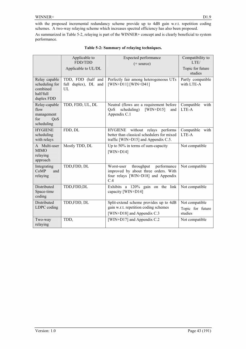
WINNER+ D1.9
Version: 1.0 Page 43 (191)
with the proposed incremental redundancy scheme provide up to 4dB gain w.r.t. repetition coding schemes. A two-way relaying scheme which increases spectral efficiency has also been proposed. As summarized in Table 5-2, relaying is part of the WINNER+ concept and is clearly beneficial to system performance.
Table 5-2: Summary of relaying techniques.
Applicable to FDD/TDD
Applicable to UL/DL
Expected performance (+ source)
Compatibility to LTE/
Topic for future studies
Relay capable scheduling for combined half/full duplex FDD
TDD, FDD (half and full duplex), DL and UL
Perfectly fair among heterogeneous UTs [WIN+D11] [WIN+D41]
Partly compatible with LTE-A
Relay-capable flow management for QoS scheduling
TDD, FDD, UL, DL Neutral (flows are a requirement before QoS scheduling) [WIN+D15] and Appendix C.1
Compatible with LTE-A
HYGIENE scheduling with relays
FDD, DL HYGIENE without relays performs better than classical schedulers for mixed traffic [WIN+D15] and Appendix C.5.
Compatible with LTE-A
A Multi-user MIMO relaying approach
Mostly TDD, DL Up to 50% in terms of sum-capacity [WIN+D14]
Not compatible
Integrating CoMP and relaying
TDD,FDD, DL Worst-user throughput performance improved by about three orders. With four relays [WIN+D18] and Appendix C.4
Not compatible
Distributed Space-time coding
TDD,FDD,DL Exhibits a 120% gain on the link capacity [WIN+D14]
Not compatible
Distributed LDPC coding
TDD,FDD, DL Split-extend scheme provides up to 4dB gain w.r.t. repetition coding schemes [WIN+D18] and Appendix C.3
Not compatible Topic for future studies
Two-way relaying
TDD, [WIN+D17] and Appendix C.2 Not compatible

WINNER+ D1.9
Version: 1.0 Page 44 (191)
6. Network Coding
6.1 Introduction Currently, most of the existing cooperative communication protocols keep information of different users separate in different orthogonal channels (orthogonal in time, frequency or spreading codes). Hence, these schemes are actually physical-layer routing (detect, replicate and forward). As a new strategy for information transmission in networks, network coding [ACL+00] allows messages from different sources (or to different sinks) to mix in the intermediate nodes hence yielding performance gains in terms of e.g., network flow, robustness or energy efficiency [X+08]. Though network coding was originally proposed for error-free computer networks, the principles of network coding can be applied also to implement wireless communications. Most methods for network coding in wireless communication [CKL06,LJS06] use binary network coding: exclusive or (XOR), which may not be optimal. For wireless cooperative networks, designed non-binary network codes can have significant performance improvement compared to binary ones. The first two innovations investigate the performance of non binary network coding in cooperative and multiple-relay scenarios. The third and fourth innovations investigate the relay selection and user grouping in a relay multiple access scenario. Finally the last innovation tackles the usage and implementation of physical network coding in a two-way relaying in an LTE system.
6.2 Proposed Innovations
6.2.1 Non Binary Network Coding in uplink relaying scenario The method consists of using non-binary network codes on top of channel codes to rebuild source information from the minimum possible set of coded blocks. In this sense, the network codes achieve the min-cut capacity for mobile or fixed relaying networks, which have the dynamic topology due to block erasures in channels. Since each transmitting block is subject to independent fading, high diversity order is achieved. Further the used linear non binary network codes are asymptotically optimal in terms of diversity (diversity order 3) as shown in [XS09]. In the following the “+” operation means the operations are in finite Galois field GF(4). Thus, it will not cause any bandwidth expansion or extra power consumption.
Figure 6-1: Two-user cooperative networks with designed non-binary network codes.
Figure 6-2: Two-user two-relay networks with network coding.
6.2.1.1 Network Coding for cooperating mobiles The scheme illustrated in Figure 6-1 uses network codes, over certain finite fields, on top of the channel codes. The relaying and local messages are encoded by network codes in the relay node (which is a user terminal in that case i..e. mobile relay and not fixed relay). The network coding scheme is fixed in each relay node (deterministic codes). The network codes are designed such that any two successfully received blocks out of four transmission blocks can rebuild two source message blocks. In the first time slot, the two source nodes use proper channel coding to transmit their own messages 1I and 2I respectively (in e.g., different frequency-orthogonal channels). In the second time slot, if both relay nodes successfully decode the channel codes, the transmitted messages for user 1 and user 2 are encoded using network

WINNER+ D1.9
Version: 1.0 Page 45 (191)
coding as 21 II + and 21 2II + , respectively. Then, the resulting blocks are channel encoded and transmitted. If a relay node cannot decode correctly, it instead repeats its own message using the same channel code. Upon receiving repeated codewords, the BS performs MRC (maximum ratio combination) of these codewords and decodes. Clearly, any two of these four blocks can rebuild the source blocks
1I and 2I , and hence a network error event occurs only when three or more blocks cannot be decoded
correctly from channels. For instance, if the BS only correctly receives blocks 211 IIC +=
and 212 2IIC += , it can decode as 211 2 CCI += , and 212 CCI += .
6.2.1.2 Network coding for multiple-user multiple-relay systems
The multiple-user multiple-relay (MUMR) wireless networks consists of M ( 2≥M ) users have independent information to be transmitted to a common base station (BS), with the help of N ( 2≥N ) relays. An illustration for MUMR network comprising of a two-user, two-relay is shown in Figure 6-2. When user nodes (user 1 and user 2) transmit to the BS, both relay nodes also receive the respective messages due to the broadcast property of the wireless medium. The relay nodes will attempt to decode, and if decoding is successful, each relay will forward the decoded messages to the BS following suitable channel and network encoding. Here successful decoding means that information is received error-free. To increase asymptotic performance, a linearly independent (LI) network codes in the two relays, as are used. Similarly to the cooperating mobiles case, the network codes are deterministic at each relay node. It follows that the BS receives four codeword transmissions with four different message combinations: I1, I2, I1+I2 and I1+2I2, constituting a resulting nonbinary LI network code. If the relay can only successfully decode one source message, it transmits the message with the same channel codeword as the source.
6.2.1.3 Performance The outage probability for the Network coding for cooperative mobiles is shown in Figure 6-3 which is extracted from [WIN+D13]. It can be clearly seen the improvement by proposed network coding systems for cooperative schemes (we call them “dynamic network codes” in the figure legend). For MUMR, Significant improvements in outage probability (and FER) are obtained in the high SNR region. One example on the FER gain is shown in Figure 6-4. For instance, in Figure 6-3 for reciprocal inter-user channels, about 2dB in SNR can be obtained from FER 310− . In Figure 6-4, about the same 2dB gain can be achieved for FER 310− for the two-user two-relay networks. The channel codes are regular LDPC codes with [200, 400, 3] matrix. All nodes have only one antenna. The relaying and BS use CRC. The channels are orthogonal, either in frequency (FDMA) or time (TDMA). We assume BPSK modulation scheme. The binary NC means both relays use binary NC, and the non-binary is LI NC.
It is interesting to note in a multi-cell scenario the relays (in the UL) will cause higher interference to neighboring BS (assuming the relay power is higher than a UT) compared to the case of 1-hop scenario. Hence the 2dB SINR gain provided by MUMR can be considered as an upper bound gain.
Figure 6-3: Outage probabilities with reciprocal
inter-user channels.
Figure 6-4: Outage probability and frame error
rates of two-user two-relay networks with network coding.

WINNER+ D1.9
Version: 1.0 Page 46 (191)
6.2.2 Network Coding for uplink relay-based wireless communication systems Very few works have examined the case of network coding for the uplink channel, and none has tackled it in a multi-cell scenario. In reality, in a wireless network system there is a limited amount of active users in a cell that need to be paired together. The first obstacle that we face is which set of users shall be selected and grouped to perform the network coding operation. Moreover, in a system where more than one relay is available per cell, the issue of relay selection arises. In fact it is not necessary that the relay close to one of the coded pair would provide the best performance. Obviously a random selection of the users and/or relays will not yield the optimal capacity of the system. Hence in [MOS08, MOS09] we proposed the usage of user grouping and relay selection whenever NC is performed in order to extract the capacity gains expected from the decrease in the number of transmissions.
6.2.2.1 User Grouping When only two users are present in a system then network coding will be applied to those two users. In reality, in a wireless network system there is a set of active users in a cell at a time from which two users shall be selected. Obviously a random selection will not yield the optimal system capacity. In fact if we choose to pair users randomly then we could end up pairing users with non-complementary channel conditions to the relay and base station, and consequently losing the advantage provided by network coding. The proposed user grouping scheme allows only one of the network coded pair to increase its SINR through the relay connection whereas the other user has to be decoded through its direct connection's SINR. A possible user grouping for a set of 6 active users is exemplified in Figure 6-5.
Figure 6-5: A possible user grouping for a set of 6 active users.
Based on the quality of the links of these users, to the relay and/or to the base station, the user grouping is carried out in order to optimize a certain cost function which can be in terms of sum-capacity, outage, interference or any other performance measure of interest.
6.2.2.2 Relay Selection In a system where more than one relay is available per cell, the issue of relay selection arises. In fact it is not necessary that the relay close to one of the coded pair would provide the best performance. When network coding is introduced, the relay selection scheme should be aware of this operation and select the best relay accordingly. Otherwise, if the relay selection choice is simply based on an individual user without any consideration to the other user in the pair, this other user could be detrimentally affected. When applying relay selection in conjunction with NC, the problem gets even more challenging. This is because the data of both sources to be encoded together should be available at the network coding node. Consequently, the relay selection algorithm should be aware of the NC operation and take into account both of the sources to be network coded when selecting the relay node. Otherwise, it could be expected that one of the network coded sources would be detrimentally affected if traditional relay selection algorithms (i.e. choosing a relay suitable to an individual source only) are applied.We specifically consider the distinct cases where network coding is performed on the relay that maximizes: 1) the capacity of the weaker source, or 2) the capacity of the stronger source, or 3) the sum-capacity of the network coded pair. More on relay selection for uplink network coding can be found in [MOS09]. The scheme selects one relay out of a set of relay nodes on which network coding of a pair of users can be performed. As multiple users are typically active at a certain time, an optimal performance could be reached if the relay selection algorithm would be performed jointly with user grouping. However, if the number of possible alternatives is too high (e.g. due to a large pool of active users that can be potentially network coded together), relay selection and user grouping can be performed separately to reduce the search window at the expense of some decrease in performance as opposed to a joint relay selection--user grouping algorithm.
WINNER+ D1.9
Version: 1.0 Page 47 (191)
6.2.2.3 Performance Simply performing network coding on the relay suitable to one of the grouped users does not guarantee a good performance. As evidenced by the capacity Figure 6-6, relay selection diversity provides a better performance as it relaxes the limitation of the connection between the users and the relays. In the legends: 'NC, S' and 'NC, W' refer to performing NC on the relay suitable for the strong user and weak user, respectively. 'NC, RS' refers to the case of relay selection diversity. Interestingly, even further gains are obtained by performing joint user grouping and relay selection. Performing NC on the relay suitable to the weak user provides a normalized mean capacity of 1.27[b/s/Hz], as opposed to 1.34[b/s/Hz] for performing random NC on the relay suitable to the strong user. Using relay selection, a normalized mean capacity of 1.69[b/s/Hz] can be obtained. This means that the joint algorithm can provide mean capacity gains of 33% and 26% as compared to performing NC on the relay suitable to the weak and strong users, respectively. Using joint user and relay grouping on a pool of 4 active users yields an additional 10% gain (not shown here) as compared to performing the relay selection algorithms on a pool of 2 active users.
6.2.3 Network coding for wireless broadcasting It has been shown in the literature that network coding can improve the transmission efficiency of wireless broadcasting as compared to traditional ARQ schemes. We propose an improved network coding scheme that can asymptotically achieve the theoretical lower bound on transmission overhead for a sufficiently large number of information blocks. Numerical results show that the proposed scheme enables higher transmission efficiencies than traditional ARQ, and previously proposed networks coding schemes for wireless broadcasting. The proposed scheme achieves an overhead reduction up to 25% compared to ARQ. Additional details are shown in the Appendix D.
6.2.4 Transmission range extension using relay station and network coding Reducing time resources from four to two slots in exchanging data blocks between the MS and BS via a relay was rendered possible thanks to the use of physical layer network coding. The proposed scheme consists of applying physical network coding principal to the two-way relaying in an LTE based scenario. Figure 6-7 illustrates the idea where the RS jointly detects individual signals sent by the BS and MS using the MIMO technique and broadcasts the codeword whose information block is the modulo-2 sum of the information blocks of the detected codewords. Recall again that in the downlink and uplink of the LTE different multiple access schemes are applied, so in the proposed transmission shall take it into account. In the multiple access time slot the MS transmits its data block in the SC-FDMA format, whereas the BS transmits concurrently its own data block in the OFDMA format. It has to be underlined that both stations use the same time and frequency slots belonging to the assigned channel. The MS which participates in the relaying process operates in the reversed direction as compared with other MSs which do not use relays in the uplink. This is our first assumption related to the proposed scheme. The RS jointly detects both data blocks using the MIMO technique. The RS we can interpret the transmission system as a virtual
0 1 2 3 4 5 60
0.1
0.2
0.3
0.4
0.5
0.6
0.7
0.8
0.9
1
Capacity [b/ s/ Hz]
cdf
NC, W
NC, S
NC, RS
Figure 6-6: Normalized capacity of NC with relay selection see [WIN+D41].

WINNER+ D1.9
Version: 1.0 Page 48 (191)
MIMO system in which out of two transmit antennas one is located in the MS and the other one is on the BS side. The RS performs soft-decoding of the codewords transmitted by the MS and BS and finds information blocks transmitted by both stations. Subsequently, the modulo-2 sum of these information blocks is calculated and re-encoded. In the broadcasting time slot the RS transmits the produced codeword in the OFDMA format using the same frequency resources again. It is further assumed: the BS is able to receive signals not only in the SC-FDMA, but also in the OFDMA mode.
a
b
RS
Relaystation
X (n)1
X (n)2
1
1
2
2
MS
BS
SC-FDMA
OFDMAOFDMA
OFDMA
Figure 6-7: Two-way relaying in the LTE with the application of MIMO and network coding in the RS.
Two-way relaying in the system with basic features of the LTE system was modelled. The performance of all the component links was estimated. These links were the links from MS to RS, from BS to RS and vice versa. Note that in the multiple access phase the suboptimum ML MIMO receiver was applied in the RS, whereas in the transmission from the RS to the BS and MS the MISO transmission with the Alamouti code was implemented. Figure 6-8 presents the BER plots on the output of the turbo code decoder when the information block length and the turbo code interleaver length were equal to 504 and 16 subcarrier OFDM/SC-FDMA blocks were applied.
4 4.5 5 5.5 6 6.5 7 7.510-5
10-4
10-3
10-2
10-1
100
SNR [dB]
BER
on
the
deco
der o
utpu
t
BER for turbo coded transmission (k=504, R=1/3, 16 subcarriers)
RS->MSRS->BSMS->RSBS->RS
Sub-ML MIMO
MISO with Alamouti code
Figure 6-8: Performance of the component links between MS and BS with the relay station.
4 4.5 5 5.5 6 6.5 7 7.510-4
10-3
10-2
10-1
100
SNR [dB]
BE
R o
n th
e de
code
r out
put
BER for turbo coded transmission (k=504, R=1/3, 16 subcarriers)
MS->BSBS->MS
Figure 6-9: Performance of two-way relaying for the transmission.
The performance of the links between the MS and BS and vice versa is shown in Figure 6-9. The quality of the whole links in the broadcasting phase is virtually determined by the MISO transmission.
6.3 Potential Impacts on Signalling and Architecture The implementation of Network Coding for cooperating mobiles will impact the signaling and architecture of LTE in particular:
• The frame structure shall be modified since two uplink phases are required, • Additional signaling since the cooperating UTs shall listen to each other, • The MAC layer should be modified to take into the user cooperation.
For the network coding for cooperative mobile method it is assumed that the UTs are transmitting and receiving at the same time. In a TDD scenario it will be challenging to implement such a case due the dynamic range problem in the transceiver and extra time slot is needed to relay partner information. In a FDD scenario it implies stringent and fast frequency swapping between the transmit and receive carriers, and extra frequency band is needed to relay the information of the partner.
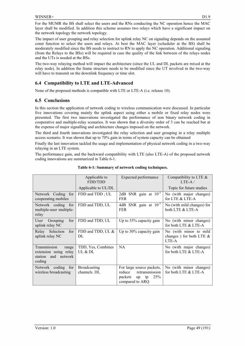
WINNER+ D1.9
Version: 1.0 Page 49 (191)
For the MUMR the BS shall select the users and the RNs conducting the NC operation hence the MAC layer shall be modified. In addition this scheme assumes two relays which have a significant impact on the network topology the network topology. The impact of user grouping and relay selection for uplink relay NC on signaling depends on the assumed const function to select the users and relays. At best the MAC layer (scheduler at the BS) shall be moderately modified since the BS needs to instruct to RN to apply the NC operation. Additional signaling (from the Relays to the BSs) will be required in case the quality of the link between of the relays nodes and the UTs is needed at the BSs. The two-way relaying method will impact the architecture (since the UL and DL packets are mixed at the relay node). In addition the frame structure needs to be modified since the UT involved in the two-way will have to transmit on the downlink frequency or time slot.
6.4 Compatibility to LTE and LTE-Advanced None of the proposed methods is compatible with LTE or LTE-A (i.e. release 10).
6.5 Conclusions In this section the application of network coding to wireless communication were discussed. In particular five innovations covering mainly the uplink aspect using either a mobile or fixed relay nodes were presented. The first two innovations investigated the performance of non binary network coding in cooperative and multiple-relay scenarios. It was shown that a diversity order of 3 can be reached but at the expense of major signalling and architecture changes imposed on the network. The third and fourth innovations investigated the relay selection and user grouping in a relay multiple access scenario. It was shown that up to 70% gain in terms of system capacity can be obtained Finally the last innovation tackled the usage and implementation of physical network coding in a two-way relaying in an LTE system. The performance gain, and the backward compatibility with LTE (also LTE-A) of the proposed network coding innovations are summarized in Table 6-1.
Table 6-1: Summary of network coding techniques.
Applicable to FDD/TDD
Applicable to UL/DL
Expected performance
Compatibility to LTE & LTE-A /
Topic for future studies Network Coding for cooperating mobiles
FDD and TDD ; UL 2dB SNR gain at 10-3 FER
No (with major changes) for LTE & LTE-A
Network coding for multiple-user multiple-relay
FDD and TDD, UL 4dB SNR gain at 10-3 FER
No (with mild changes) for both LTE & LTE-A
User Grouping for uplink relay NC
FDD and TDD, UL Up to 35% capacity gain No (with minor changes) for both LTE & LTE-A
Relay Selection for uplink relay NC
FDD and TDD, UL & DL
Up to 30% capacity gain No (with minor to mild changes ) for both LTE & LTE-A
Transmission range extension using relay station and network coding
TDD, Yes, Combines UL & DL
NA No (with major changes) for both LTE & LTE-A
Network coding for wireless broadcasting
Broadcasting channels. DL
For large source packets, reduce retransmission packets up tp 25% compared to ARQ
No (with minor changes) for both LTE & LTE-A
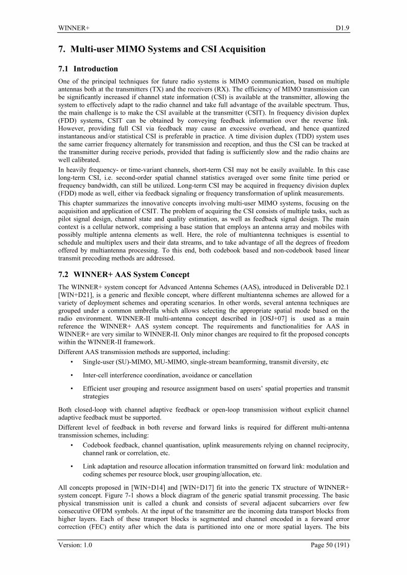
WINNER+ D1.9
Version: 1.0 Page 50 (191)
7. Multi-user MIMO Systems and CSI Acquisition
7.1 Introduction One of the principal techniques for future radio systems is MIMO communication, based on multiple antennas both at the transmitters (TX) and the receivers (RX). The efficiency of MIMO transmission can be significantly increased if channel state information (CSI) is available at the transmitter, allowing the system to effectively adapt to the radio channel and take full advantage of the available spectrum. Thus, the main challenge is to make the CSI available at the transmitter (CSIT). In frequency division duplex (FDD) systems, CSIT can be obtained by conveying feedback information over the reverse link. However, providing full CSI via feedback may cause an excessive overhead, and hence quantized instantaneous and/or statistical CSI is preferable in practice. A time division duplex (TDD) system uses the same carrier frequency alternately for transmission and reception, and thus the CSI can be tracked at the transmitter during receive periods, provided that fading is sufficiently slow and the radio chains are well calibrated. In heavily frequency- or time-variant channels, short-term CSI may not be easily available. In this case long-term CSI, i.e. second-order spatial channel statistics averaged over some finite time period or frequency bandwidth, can still be utilized. Long-term CSI may be acquired in frequency division duplex (FDD) mode as well, either via feedback signaling or frequency transformation of uplink measurements. This chapter summarizes the innovative concepts involving multi-user MIMO systems, focusing on the acquisition and application of CSIT. The problem of acquiring the CSI consists of multiple tasks, such as pilot signal design, channel state and quality estimation, as well as feedback signal design. The main context is a cellular network, comprising a base station that employs an antenna array and mobiles with possibly multiple antenna elements as well. Here, the role of multiantenna techniques is essential to schedule and multiplex users and their data streams, and to take advantage of all the degrees of freedom offered by multiantenna processing. To this end, both codebook based and non-codebook based linear transmit precoding methods are addressed.
7.2 WINNER+ AAS System Concept The WINNER+ system concept for Advanced Antenna Schemes (AAS), introduced in Deliverable D2.1 [WIN+D21], is a generic and flexible concept, where different multiantenna schemes are allowed for a variety of deployment schemes and operating scenarios. In other words, several antenna techniques are grouped under a common umbrella which allows selecting the appropriate spatial mode based on the radio environment. WINNER-II multi-antenna concept described in [OSJ+07] is used as a main reference the WINNER+ AAS system concept. The requirements and functionalities for AAS in WINNER+ are very similar to WINNER-II. Only minor changes are required to fit the proposed concepts within the WINNER-II framework. Different AAS transmission methods are supported, including:
• Single-user (SU)-MIMO, MU-MIMO, single-stream beamforming, transmit diversity, etc
• Inter-cell interference coordination, avoidance or cancellation
• Efficient user grouping and resource assignment based on users’ spatial properties and transmit strategies
Both closed-loop with channel adaptive feedback or open-loop transmission without explicit channel adaptive feedback must be supported. Different level of feedback in both reverse and forward links is required for different multi-antenna transmission schemes, including:
• Codebook feedback, channel quantisation, uplink measurements relying on channel reciprocity, channel rank or correlation, etc.
• Link adaptation and resource allocation information transmitted on forward link: modulation and coding schemes per resource block, user grouping/allocation, etc.
All concepts proposed in [WIN+D14] and [WIN+D17] fit into the generic TX structure of WINNER+ system concept. Figure 7-1 shows a block diagram of the generic spatial transmit processing. The basic physical transmission unit is called a chunk and consists of several adjacent subcarriers over few consecutive OFDM symbols. At the input of the transmitter are the incoming data transport blocks from higher layers. Each of these transport blocks is segmented and channel encoded in a forward error correction (FEC) entity after which the data is partitioned into one or more spatial layers. The bits
WINNER+ D1.9
Version: 1.0 Page 51 (191)
mapped to each layer are separately modulated. In case of single carrier uplink transmission the transmitted data is subject to an additional Discrete Fourier Transform (DFT) operation referred to as generalized multi-carrier (GMC) processing in Figure 7-1. The data transmitted on each layer is further subject to linear dispersion coding or linear precoding. Finally, the generated antenna signals for all the layers are summed over the antennas and OFDM modulation per antenna is performed.
Figure 7-1: Generic transmitter (source WINNER-II).
7.3 Proposed Innovations and Performance
7.3.1 Enhancements for codebook based multi-antenna transmission This section summarizes advanced methods to interference mitigation and avoidance for the cellular multiantenna downlink transmission systems employing codebook based precoding, where the downlink transmit precoders are chosen from pre-defined sets. Conventionally, the terminals estimate their channels based on common downlink pilot signal, and directly feedback their preferred precoder choices to the base station. In the proposed innovations, both intra-cell and inter-cell interference are considered. The improvement arises from interference management solutions that enable either interference rejection receiver processing in terminals, or interference avoidance scheduling in the network side. The adaptive FDD MIMO transmission solution developed in WINNER II [WIN2D61310] for wide-area environments is based on fixed unitary pre-coding weights derived from the DFT matrix. The concept is called Grid of Beams (GoB), since when employed with uniform linear antenna arrays, the precoders form directional beams. The contributions presented in this section are well aligned with the GoB concept. However, more general precoding and antenna array geometries can be readily supported as well. Due to the codebook-based nature, the proposals can also be easily embedded into the LTE standard. Adaptive MIMO transmission In the context of GoB, the practical performance limitations of adaptive MIMO transmission in wide-area were examined in [WIN+D14 Section 2.1.2]. There, the main contribution is in multiantenna receiver processing and CQI reporting. The UTs are assumed to provide frequency-selective CQI feedback per chunk for both single- and multi-stream transmission. In particular, optimization with respect to the SINR conditions at the receiving side is performed, and the achievable post-equalization SINR is reported as CQI. At the BS, an extended score-based scheduler is used, which is able to switch adaptively between single- and multi-stream transmission, depending on the reported CQIs. In a multi-cellular simulator assuming ideal channel knowledge, a capacity increase of the mean sector spectral efficiency by a factor of 1.9 for the adaptive MIMO 2x2, and by 3.5 for the adaptive 4x4 system with respect to the SISO reference case, is observed. In Appendix E.3, further simulation results with interference-aware score-based fair scheduling are provided. The evaluated scenario assumes symbol-synchronism between cells and fixed pre-coding beams. Thus, multi-cell channel estimation based on virtual pilots [WIN+D14 Appendix B.1] is enabled so that each UT can estimate the beam responses of the interfering data streams transmitted by the neighbouring BSs. As a result, UTs may construct correlation-based interference covariance matrix estimates, which enables efficient interference rejection combining (IRC). The effect of inaccuracy in channel estimation and

WINNER+ D1.9
Version: 1.0 Page 52 (191)
interference covariance estimation is evaluated in [WIN+D14 Appendix A.1]. According to the results, in a synchronized network the system throughput is not sensitive to the estimation errors. The work on adaptive MIMO transmission was extended in [WIN+D17 Section 2.4], where the predicting of future channels was addressed. In a practical system, evaluation of the SINRs at the terminal will be carried out based on the channel measured at time instant while the scheduling decision will be applied at the subsequent time instants, resulting in a delay. During this time, the channel may change, so that the SINR conditions determined from the measured channel may no longer be valid. In this innovation, a practical channel prediction method is proposed. For channel prediction, the channels measurements gathered up to a given time instant as well as statistical information on the channel dynamics can beneficially be used. This innovation concerns predictive estimation of the channel and CQI in a rather specific setup, where a vehicular terminal has ULA antenna setup, i.e. correlated antennas within half wave length distance to each other. Adaptive MIMO mode switching with different levels of multi-site cooperation was addressed in [WIN+D14 Section 2.1.1]. In multicell systems, different levels of cooperation between neighbouring cells can be applied. In a certain time-frequency resource, a mobile can be served in one of the following MIMO modes: A) SU-MIMO: Multiple spatial data streams towards a single user, B) MU-MIMO: Multiple spatial data streams towards multiple users, C) Spatial interference avoidance based on beam coordination: exchanging resource restrictions to avoid spatial collisions. Here, option C requires information exchange between the BSs. In order to keep the backhaul traffic moderate, option C should only be used for cell-edge users. Intra-cell and inter-cell interference avoidance by partial CSIT sharing The objective of this concept [WIN+D14 Section 2.1.3], is to reduce intra-cell and/or inter-cell interference in downlink FDD MIMO systems that employ codebook-based linear precoding. The aim is to provide additional codebook-based channel state information in addition to the existing best weight indices (called PMI in LTE) in order to reduce the interference in the overall system. Interference is reduced by better support for beam pairing. The approach for avoiding intra-cell interference in MU-MIMO is depicted in Figure 7-2. Here, a novel signaling concept called “best companion” is introduced.
DL Reference symbols
Codebook
PMI, CQI+ BCI, delta CQI
User 1
User k
User j
DL FDD
……w22w11
Weightvector
Index
……w22w11
Weightvector
Index
Potential partners of user 1:PMIk,j == BCI1
Figure 7-2: Improved reporting scheme for MU-MIMO mode.
• The UTs measure the channel, and report the best beam index (rank 1 PMI) for their serving cell, i.e. the codebook index of the transmit precoder that maximizes the SINR at the receiver output.
• The UTs report best-companion indexes (BCI) for the serving cell, i.e. the index of the least interfering potential co-scheduled precoder, which maximises the SINR at the receiver output, assuming the transmission of PMI and candidate BCI.
• The UTs report the CQI for the case that the BCIs are not used. For the case that the BCIs are used, a delta-CQI is reported.
Based on the additional information, for dual stream MU-MIMO, the base station now can pair two users n and m so that the PMI of m is the BCI of n and vice versa. As a result, spectral efficiency will be increased. A similar approach for avoiding inter-cell interference is developed as well.
• The UTs measure the channel and report the best beam index (preferred rank 1 PMI) for their serving cell.
• The UTs further measure the channels from a set of dominant interfering cells, and report BCIs or worst-companion PMIs (WCI) for the set of interfering cells.
WINNER+ D1.9
Version: 1.0 Page 53 (191)
• The UTs report the CQI for the case that the BCIs are not used, and for the case that the BCIs are used or the WCIs are not used (the latter may be in the form of a delta-CQI).
Based on this additional information, multi-cell beam coordination can now occur. As a result, especially the cell edge user throughput will be increased. Simulation results for inter-cell interference avoidance are provided in [WIN+D14 Appendix A.2]. The results show a performance gain of +16% for an urban macro channel and a gain of +22% for an urban micro channel in terms of average cell throughput.
7.3.2 Feedback methods for multi-user MIMO zero-forcing Another approach for downlink multi-user MIMO is to allow adaptive generic precoder design that does not employ pre-defined static precoder sets. The approach allows the base station more freedom to control or nearly null intra-cell interference. On the other hand, this freedom mandates that each downlink data stream has to be accompanied with a dedicated, precoded demodulation pilot. This section summarizes two methods for downlink multi-user zero-forcing by transmit-receive processing based on limited feedback. The first scheme is based on feedback of CSI, where the channel quantization is based on hierarchical codebooks. The hierarchy can take advantage of slow channel fading rate, as the CSIT is refined over several feedback periods. The second scheme proposes to use a combination of long term channel statistics and instantaneous feedback from the mobile. The channel statistic can be gathered via low-rate feedback in FDD mode or alternatively by reverse link measurements in TDD mode. Again, the long-term statistics are most useful when the MIMO channel has strong and slowly changing directional components. Joint transmit-receive optimisation and user scheduling for FDD downlink A multi-user MIMO transceiver architecture and methodology is proposed [WIN+D14 Section 2.2.1, Appendix A.3], [WIN+D41 Section 5.2], under the assumption of limited CSIT, based on linear zero-forcing beamforming and linear receiver combining. This proposal is motivated by a downlink FDD cellular network where a base station equipped with M>1 antennas serves a large number (K>M) of users, each equipped with N>1 antennas. The channel is first estimated by each user, and CSI feedback and the receiver combiner for each user are jointly computed to maximize a novel metric based on the signal-to-interference-plus-noise ratio (SINR) at the combiner output. The actual SINR achieved during data transmission is a function of the beamforming weights. However, as users cannot know the beamforming weights in advance, the metric is based on an expectation of the SINR. This combining strategy is called the maximum expected SINR combiner (MESC). Once the transmitter receives the CSI feedback from all K users, it determines the set of users to serve in order to maximize the weighted sum rate. During the data transmission, serviced users can demodulate the data using the previously derived MESC or using an enhanced combiner that requires knowledge of the beamformed MIMO channel for maximizing the actual SINR. The assumption is that UTs feedback – along with CQI – quantized channel direction information (CDI), estimated based on downlink common pilot. Typically, the feedback bits are used to index a set of vectors (or codewords) in a codebook C which is known to the transmitter and all receivers. For example, B bits per feedback interval can be used to index a codebook with 2B vectors. For a transmitter with M antennas, each codeword in C is an M-dimensional vector that characterizes the MIMO channel for that user. A well-designed codebook will contain codewords that effectively span the set of MIMO channels experienced by the users. A practical, highly adaptable technique for generating codebooks suited for any antenna configuration and level of spatial correlation is proposed, based on the Lloyd-Max algorithm. In practice, codebook generation would be performed offline for a large variety of channel environments, and each user would measure the MIMO channel statistics and load an appropriate codebook from memory. Different codebooks can be loaded if the mobile moves to a different spatial environment, for example, from outdoors to indoors. The proposed codebook design creates a nested structure that lends itself to hierarchical indexing. As a result, CSI feedback can be accumulated over multiple signaling intervals in order to index a much larger codebook which results in improved performance for low mobility users. The simulation results in a multi-cell environment with a spatial channel model show approximately a 50% improvement in median cell throughput thanks to hierarchial indexing. Efficient feedback schemes combining long term and short term information Again, the downlink of a multi-user system with multiple antennas at each end is considered in this proposal [WIN+D14 Section 2.2.2], [WIN+D41 Section 5.3]. The transmitter is assumed to have long-term covariance information about the MIMO channels for each user. Each UT, in addition to the covariance information, also estimates the instantaneous channel based on common pilot transmissions. The information of the instantaneous channel state is provided in the form of quantized CQI feedback of sufficiently low dimensionality so as to keep the feedback overhead at a minimum. Here, the CQI indicates the effective MIMO channel norm. The base station utilizes the long-term statistics and the CQI feedback to employ user scheduling and multi-user transmit beamforming, where the beamforming is

WINNER+ D1.9
Version: 1.0 Page 54 (191)
based on zero-forcing of the user-specific eigenbeams. On the other hand, the receivers employ linear interference cancellation. For the purposes of scheduling, SINR of each selected beam needs to be estimated. The estimator can be formulated in closed form. According to the simulations, very few bits (3-5) for the CQI feedback per user are needed in order to approach the throughput performance of unquantized feedback. On the other hand, the knowledge of long term channel statistics can be collected at the BS using low rate feedback from the UTs, or alternatively it can be estimated on the reverse link without any additional signalling. This study continued in [WIN+D17 Section 2.2], where it was noted that the CQI estimation performance affects the system throughput more than CQI quantization. In order to mitigate the problem, a training based estimation scheme is proposed that allows for a direct estimation of the channel norm in addition to the instantaneous channel. The long term information is exploited in the design of the training scheme. Here, the pilot precoder matrices are optimized per user for the estimation of the effective channel norm in terms of mean-squared-error. Thus, common pilot is no longer applicable, but downlink dedicated pilots for each user are needed to support the feedback.
7.3.3 Resource allocation schemes for TDD systems This section summarizes advanced methods for resource allocation and multi-user MIMO precoding in cellular TDD systems. In networks employing TDD, unquantized instantaneous CSIT can be obtained at the transmitter. This allows more advanced or accurate multi-user interference balancing or zero-forcing to be performed by the base station. The benefits of TDD are best available in local and metropolitan area deployments, where the cell sizes are relatively small and the channel changes slowly so that the coherence time is longer than a TDD frame. The assumption is that the uplink and downlink MIMO channels are reciprocal, and that the transmit and receive RF chains in all transceivers are well calibrated. In order to facilitate multi-user MIMO precoding in the downlink, mutually orthogonal antenna-specific uplink sounding pilot signals were defined in WINNER II. The number of mobile antennas to be served in the same resource block defines the amount of orthogonal pilot resources needed. Thus the number of users that can be tracked simultaneously is limited by the pilot overhead. Note that the uplink pilot is needed to keep the downlink MIMO channel open even when the mobile has no data to transmit. If the traffic in uplink and downlink is relatively symmetric, the same subcarriers can be allocated to the same set of users in both directions. In this case the uplink data demodulation pilot can be re-used as a reference for downlink transmit precoding as well. In addition to channel sounding, some form of scalar CQI feedback is needed to support rate allocation and adaptive modulation. This is due to the fact that the interference levels are not reciprocal, and the transmitter should know the SINR seen by the receiver. Downlink resource allocation for multi-user MIMO-OFDM TDD system with linear transceiver processing The focus in this concept [WIN+D14 Section 2.3.1] is on spatial user scheduling with greedy beam/user selection combined with various linear transceiver design techniques with a near perfect transmitter CSI. The proposed greedy beam allocation allows efficient grouping of non-interfering users and/or streams/beams across different, often non-correlated frequency and time dimensions. While the maximum number of beams is limited by the number of BS transmit antennas, the number of beams per user can get any value between zero and the number of terminal antennas depending on the channel conditions. At the same time, the advanced precoder design (TX weight and power allocation) algorithms can be used to guarantee user/stream QoS requirements while maximising the system optimisation objectives. Unlike conventional schemes, the proposed design method can be optimised according to different objectives, including: • Power minimisation subject to per stream SINR or rate constraints • Minimum weighted SINR maximisation, i.e. SINR balancing • Weighted sum rate maximisation • Weighted common rate maximisation, i.e. weighted rate balancing The transceiver optimisation method can handle additional constraints, such as a guaranteed minimum bit rate per user, upper or lower bounds for the SINR values of data streams, as well as per antenna or per BS power constraints. The feasibility of the resulting optimisation problems can be easily verified. A practical model for the rate provided by each data stream can be easily adapted. The achievable rate per stream can be modelled for example as min(log2(1 + Γγs), rmax), where Γ describes the SINR gap to the channel capacity, γs is the SINR of stream s and rmax is the maximum rate limit, both imposed by the set of practical modulation and coding schemes. The optimisation problems are decomposed into a series of remarkably simpler subproblems which can be efficiently solved by using standard geometric program and/or second order cone program solvers. Even though each subproblem is optimally solved, the global optimum cannot be guaranteed in general

WINNER+ D1.9
Version: 1.0 Page 55 (191)
due to the nonconvexity of most linear transceiver optimisation problems. However, the algorithms have been shown to converge fast to a solution, which can be a local optimum, but remains efficient. Multi-user MIMO downlink precoding for time-variant correlated channels This concept [WIN+D17 Section 2.1] presents a novel method for low-rank modeling and averaging of the long-term CSI, estimated over a finite time and frequency bandwidth. Long-term CSI can be applied to any previously introduced multi-user MIMO precoding techniques – such as block diagonalization (BD) and regularized block diagonalization (RBD) – originally requiring perfect CSI at the BS. The method relies on the existence of uplink CSI sounding signals. Here, the BS measures the spatial channel covariance matrices over the frequency selective and time-varying channel per terminal antenna. The dominant eigenmode of each antenna-specific matrix is then determined, and the equivalent MIMO channel – to be used as a reference for precoding – for each user is modeled as the combination of these eigenmodes. The innovation provides a rather smooth transition from instantaneous CSIT to statistical CSIT. Simulation results, assuming noise-free channel estimation, indicate that a significant performance improvement is achieved by the new approach as compared to the state of the art modeling of long-term CSI, especially in the case when a user has a line of sight (LOS) channel. Pilot overhead reduction for multi-user MIMO systems in TDD mode Antenna-specific uplink CSI sounding pilot streams cause an extensive overhead that restricts the size of the practical user group and the terminal antenna setup that can be handled within the same time-frequency slot. The goal of this concept, introduced in [WIN+D17 Section 2.3], is to reduce the required sounding overhead by letting the terminals form a reduced number of uplink pilot beams by transmit precoding, instead of transmitting antenna-specific pilots. As a result, the number of the required orthogonal uplink pilot resources reduces. In the simplest form of operation, terminals may be treated as single-antenna devices. The sounding beams can be formed based on the knowledge of the user-specific MIMO channels, obtained via a downlink common pilot signal. This way part of the signaling overhead is moved to the downlink, which is more resource efficient. The use of this concept requires that the common pilot should be distributed across the entire bandwidth with a reasonable density also in TDD mode. The innovation improves the system performance while reducing the signaling overhead. This is due to the power efficiency of the sounding: Uplink transmit power is not wasted on weak eigenmodes that are unlikely to be utilized for downlink data transmission. Another benefit is that the physical layer specifications of the communication system, such as LTE-A, do not need to explicitly support arbitrarily large or odd numbers of antennas at the terminal. UT can mimic to have some specification compliant number of virtual antennas, e.g., a UT with five antenna elements may appear as a virtual two-antenna UT to the BS.
Figure 7-3: Reduced overhead CSI sounding: pilot and data signaling stages.
The problem of CSI sounding for multi-cell or CoMP environments is addressed briefly in Appendix E.4. The main extension there is in informing each BS of the spatial modes already occupied in the neighbouring cells so that coordinated beamforming can be supported. Uplink-downlink multi-user SDMA strategy for TDD-MIMO systems This contribution, introduced in [WIN+D14 Section 2.3.2], proposes a practical uplink MIMO scheme for time division duplex (TDD) systems to co-exist with downlink multi-user transmit-receive zero-forcing so that the locally available CSI of the block diagonalized channel is used by the terminals in the uplink transmission. Uplink transmit beamforming gain is significant especially when the base station employs a relatively small antenna array. The precoded pilot symbols are sufficient in both uplink and downlink to satisfy the needs of both transmission and reception. The base station selects the same set of spatially compatible eigenbeams for both directions. The existence of the downlink beams accommodates reciprocal beamforming for uplink. In essence, the uplink is based on reversing the downlink signal processing chain, and the same space and frequency
WINNER+ D1.9
Version: 1.0 Page 56 (191)
resources are reserved for both directions. If the data traffic between uplink and downlink is heavily asymmetric, the asymmetry can be dealt with by uneven allocation of resources in time domain. The concept is based on linear multi-user transmit-receive zero-forcing. The multi-user MIMO channel is effectively decoupled into a set of parallel single-user MIMO channels so that per-user precoding based on SVD can be performed. In the uplink, each mobile only sees its own zero-forced MIMO channel and thus implicitly assumes a zero-forcing receiver in the base station. However, in practice other multi-user receivers than zero-forcing can be applied to improve the robustness of the system. The main innovative idea is in coupling the uplink and downlink MIMO transmission so that they support each other. Here, the data-stream-specific precoded downlink pilots are sufficient for creating uplink precoders. The proposed concept utilizes all spatial degrees of freedom while taking advantage of CSIT. Thus both multiplexing gain and beamforming gain are obtained, which is a combination not found in the current uplink solutions.
7.3.4 New concepts in coding and decoding This section presents innovative concepts related to coding and decoding in the general context of point-to-point communication. The first concept proposes the use of network coding methods for MIMO transmission, with the aim to provide diversity-multiplexing trade-off. In the second concept, an improved generic iterative joint channel estimation and decoding architecture employing belief propagation is presented. The third concept proposes a transparent antenna switched transmit diversity scheme for the uplink. Space-time network coding The proposed method [WIN+D17 Section 4.1] consists of imitating network coding at the space-time encoder of a multi-antenna transmitting node in order to combine the symbols of various data streams and consequently increase the space-time encoder data rate. The code design is divided into two categories. In the first category, network coding at the transmitter source is used to obtain multiplexing gain and low diversity. In the second category, a trade-off between diversity and multiplexing gain can be obtained. The proposed method can obtain adaptively some tradeoff between diversity and multiplexing gains without requiring any channel state information at the transmitter (CSIT). The receiver needs to know the scheme used at the transmitter. In addition, depending of the transmitted code matrix the CSIT may be required at the transmitter. Joint channel estimation and decoding using Gaussian approximation in a factor graph The general receiver processing problem of joint channel estimation, equalization and decoding was addressed in a concept [WIN+D17 Section 4.2] employing an iterative belief propagation algorithm. The novel idea is to model the probability distributions as mixtures of Gaussian distributions. The approach allows for estimation improvement and complexity reduction simultaneously. In Appendix E.2, the concept is extended from single-carrier to multi-carrier modulation. The appendix addresses channel estimation in time and frequency domains, and provides simulation results. Tile-switched transmit diversity The presented uplink technique uses the basic idea of transmit antenna selection, and benefits from the frequency selectivity of the channel by means of channel coding. It requires the implementation of two transmit antennas at the mobile station but is fully transparent to the base station like cyclic delay diversity (CDD) transmission. However, compared to CDD transmission, it has better or equal performance in fading environments and significantly better performance in environments with a line-of-sight channel. For more details and performance results see Appendix E.1.
7.4 Potential Impacts on Signalling and Architectures Most of the proposed concepts have relatively minor impacts on the system architecture or signalling. The adaptive FDD MIMO transmission solutions for wide-area environments are well aligned with the general GoB concept. However, more general precoding and antenna array geometries can be readily supported as well. Thus, the codebook-based concept proposals can be easily embedded into the LTE standard. Multi-site cooperation with adaptive MIMO mode switching requires additionally a low latency information exchange between multiple sites. TDD frame and pilot signal structure of LTE-A are proposed to support precoded stream-specific pilots. In the downlink, these pilots are sufficient. However, changes to the uplink are suggested so that the pilots are appended by additional streams, resulting in each user's pilot precoder matrix becoming unitary. The number of users that can be tracked simultaneously is limited by pilot overhead in TDD mode. Note that the uplink pilot is needed to keep the downlink MIMO channel open even when the mobile has no data to transmit. In order to be able to reduce the required uplink pilot overhead caused by CSI sounding, it is beneficial to have common pilot distributed across the entire bandwidth. Furthermore, the base station may inform the terminals of the number of allowed CSI sounding beams per user. Alternatively,

WINNER+ D1.9
Version: 1.0 Page 57 (191)
an advanced terminal may choose a number independently so that the BS does not need to know how many antennas the terminal actually has. Even if perfect CSIT is available in TDD systems, some form of scalar feedback is needed to support rate allocation and adaptive modulation. This is due to the fact that the interference levels are not reciprocal, and the transmitter should know the SINR seen by the receiver. The frame structure in the LTE TDD mode has some potential shortcomings. In the LTE system, the minimum switching time between uplink and downlink is 5 ms. This limits the usability of methods that utilise channel reciprocity for acquiring CSIT. For example in the WINNER-II proposal, two consecutive slots can be used for the uplink and downlink, which allows a very short loop in the system (0.35 ms downlink/uplink switching time). It could be beneficial to have a more flexible frame structure also in the LTE-Advanced system, thereby allowing network operators to optimize the frame structure for a given deployment scenario.
7.5 Compatibility to LTE and LTE-Advanced LTE supports multi-antenna transmission using two or four antenna ports. Four multi-antenna transmission schemes are defined in downlink, in addition to single antenna transmission:
• Transmit diversity • Closed-loop spatial multiplexing using code-book based precoding • Closed-loop non-codebook-based single-stream beamforming (based on user specific reference
signals) • Open-loop spatial multiplexing
The 3GPP technical report [3GPP36814] describes the potential physical layer advancements to be included in LTE-Advanced. LTE-Advanced will support spatial multiplexing with up to four layers on the uplink. Furthermore, it will extend the downlink spatial multiplexing with up to eight layers. Downlink reference signals targeting user data demodulation will be UT-specific, i.e., user data and the demodulation reference signals intended for a specific UT are subject to the same precoding operation. The design principle for the demodulation reference signals is an extension to multiple layers of the concept of Rel-8 UT-specific reference signals used for beamforming. This enables the support for multiple advanced AAS features in LTE-Advanced, including different multi-user (MU)-MIMO approaches and coordinated multipoint transmission/reception methods (CoMP). Multiple changes are required on top of LTE rel.8. Modifications or extensions to CQI feedback reporting are required, including, for example, CDI reports and “best companion indices”. Information exchange via X2 interfaces must be improved as the best companion index needs to be communicated between sites. Furthermore, a new pilot structure and synchronism between BSs has been proposed for improved multi-cell channel estimation. Finally, LTE rel.8 does not offer UT-specific sounding pilots for more than one stream which are required by most of the proposed concepts for TDD. Also, the support for uplink multistream transmission is needed in order to fully support the DL assisted UL SDMA proposal.
7.6 Conclusions This section discussed the innovative concepts proposed in the field of Advanced Antenna Schemes. The WINNER+ multi-antenna concept must support multiple scenarios with different spatial/temporal channel characteristics. Users with low velocity may benefit from closed-loop transmission with different feedback rates while high velocity users must rely on open-loop transmission based on, e.g., per antenna rate control or space-time-frequency coding. Users located in environments with low angular spread, including rural and wide area scenarios can be served by adaptive beamforming or code-book-based precoding relying mostly on statistical CSI and simple CQI feedback. In environments with high angular spread such as urban local area scenario there is a possibility to have more reliable instantaneous CSI via uplink sounding, thus allowing for the use of more sophisticated MU-MIMO precoding schemes. For a given deployment scenario, an appropriate spatial scheme must be chosen. As the user is moving in the network, the transmission must be adapted continuously to the spatial properties of the channel and the interference. The innovations introduced in WINNER+ focus mostly on seeking for system performance improvements from advances in the acquisition of CSIT – short term or long-term – via new signaling and estimation solutions. For example, for the FDD mode, interference aware scheduling, enabled by multicell channel estimation by the UTs in a synchronized network, is proposed. New feedback signaling schemes to support beam scheduling with the objective of avoiding both intra-cell and inter-cell interference is also suggested. For the TDD mode, a concept that reduces the uplink CSI sounding overhead without loss in the system throughput is introduced. In the TDD mode, very general linear MU-MIMO transmit precoder designs can be applied. These designs can be employed by the decision of the network vendor, without the need for them to be defined by the communication system standards. Thus, optimisation methods for maximising various system performance objectives can be directly applied in the precoder design.

WINNER+ D1.9
Version: 1.0 Page 58 (191)
The performance gain, and the backward compatibility with LTE of the proposed AAS innovations are summarized in Table 7-1.
Table 7-1: Summary of AAS innovations.
Applicable to FDD/TDD
Applicable to UL/DL
Expected performance (+ source)
Compatibility to LTE and LTE-A /
Topic for future studies
Enhancements for codebook based multi-antenna transmission
FDD (and TDD)
downlink
Improved spectral efficiency for cell-edge
users (D1.4, D1.7, Appendix E)
Not directly compatible to LTE: feedback signaling changes
needed / Can be considered for LTE-A
Feedback methods for multi-user MIMO zero-forcing
FDD (and TDD)
downlink
Improved spectral efficiency in environments
with high antenna correlation
(D1.4, D1.7)
Not compatible to LTE / Can be considered for LTE-A (DL precoded demodulation
pilot used)
Resource allocation schemes for TDD systems
TDD downlink and uplink
Highly increased overall performance if accurate
CSI available (D1.4, D1.7, Appendix E)
Not directly compatible to LTE: multiantenna UL sounding pilot
needed / Can be considered for LTE-A (pilot signaling expected to be
compatible) Coding and decoding Any duplexing
mode and link Provides diversity, coding,
and decoding gain for point-to-point links
Mostly readily applicable to LTE
Space-time network coding for further studies

WINNER+ D1.9
Version: 1.0 Page 59 (191)
8. Quality of Service Control
8.1 Introduction Modern wideband communication systems present a very challenging multi-user communication problem: many users in the same geographic area require high on-demand data rates in a finite bandwidth with a variety of heterogeneous services such as voice (VoIP), video, gaming, web browsing and others. Emerging broadband wireless systems such as 3GPP LTE employ Orthogonal Frequency Division Multiple Access (OFDMA) as multiple access scheme. OFDMA allows to exploit multi-user diversity as well as to flexibly support mupliple users with varying applications, data rates, and Quality of Service (QoS) requirements. Cross-layer scheduling algorithms strive to satisfy QoS requirements as well as to exploit channel diversity between users. Naturally, the QoS control approaches presented in this section are closely related to the resource allocation and scheduling schemes elaborated in Section 2.2.1 The QoS related innovations reported in WINNER+ deliverables [WIN+D11], [WIN+D15] are described in the following sections. A scheduling approach applicable to a mixed service classes scenario, including delay sensitive services, is presented in Section 8.2.1. A framework for cross-layer design is introduced in Section 8.2.2. The objective is to jointly optimize the resource allocation at the scheduler together with tuning the data rates at the application layer, such that users are served with the best possible perceived quality,. In Section 8.2.3 information about the applications and the channel is used for admission control considering QoS requirements. An essential condition for application aware RRM is the identification of different traffic flows at the link layer. This topic is treated in Section 8.2.4, including specific requirements of relays.
8.2 Proposed Innovations
8.2.1 HYGIENE scheduling HYGIENE (HurrY-Guided-Irrelevant-Eminent-NEeds), is a scheduling algorithm for heterogeneous traffic scenarios [CCK09]. HYGIENE scheduling is based on the three following steps. First a Rushing Entity Classifier (REC) identifies rushing entities that must be treated with higher priority. Depending on the nature of the traffic, entities are UTs (NRT traffic) or packets (RT). Therefore, rushing entity classification is traffic-dependent.. In a second step, HYGIENE deals with urgencies. Rushing entities are scheduled regardless of their momentary link quality. If any resources (here chunks) are still unscheduled, then in a third step, HYGIENE allocates resources to those users with better momentary link quality, regardless of their time constraints. These three steps are described in detail in [WIN+D15], and in Appendix C.5.
8.2.1.1 Performance and benefits In [WIN+D15], [CCK09] HYGIENE scheduling is compared with schedulers common in the literature. To put it in a nutshell, the results obtained for OFDMA wireless cellular networks, reveal that while early deadline first (EDF) scheduling does not profit from multi-user diversity, Max C/I and proportional fair schedulers targets at maximizing the cell throughput regardless of the user’s QoS constraints. Simulation results reported in [WIN+D15], Appendix 9.1.1.2, show that HYGIENE is a highly flexible and effective scheduler for a mix of multi-media applications. HYGIENE scheduling is extended so to support relays in Section 5.2.1.3, and its performance is presented in Appendix C.5.
8.2.1.2 Requirements on signalling, architecture and protocols As the scheduler is typically not standardized, HYGIENE scheduling should not introduce special additional requirements on signalling, architecture and protocols, compared to state of the art algorithms for LTE and LTE-Advanced.
8.2.2 Cross-Layer Optimization (CLO) Between Link and Application (APP) Layer We consider resource allocation on shared wireless downlink, where K applications (users) are served by the base station. Possible applications include video and audio streaming, web browsing or file download. At the link layer a scheduler distributes the wireless resources among the users. For cross-layer optimization (CLO) the resource allocation at the link layer and the resource consumption of the application (APP) layer are tuned by an optimizer. The basic idea of CLO is that the data rates offered by the APP layer are adjusted, so to take into account the channel conditions of the wireless link, the number of users to be served, as well as other QoS constraints. One essential condition for applying
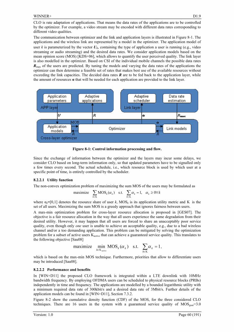
WINNER+ D1.9
Version: 1.0 Page 60 (191)
CLO is rate adaptation of applications. That means the data rates of the applications are to be controlled by the optimizer. For example, a video stream may be encoded with different data rates corresponding to different video qualities. The communication between optimizer and the link and application layers is illustrated in Figure 8-1. The applications and the wireless link are represented by a model in the optimizer. The application model of user k is parameterized by the vector Uk, containing the type of application a user is running (e.g., video streaming or audio streaming) and the desired data rates. We consider application models based on the mean opinion score (MOS) [KDS+06], which allows to quantify the user perceived quality. The link layer is also modelled in the optimizer. Based on CSI of the individual mobile channels the possible data rates Rmax of the users are predicted. By tuning the models and varying the data rates of the applications the optimizer can then determine a feasible set of rates that makes best use of the available resources without exceeding the link capacities. The decided data rates R are to be fed back to the application layer, while the amount of resources α that will be needed for each application are provided to the link layer.
Figure 8-1: Control information processing and flow.
Since the exchange of information between the optimizer and the layers may incur some delays, we consider CLO based on long-term information only, so that updated parameters have to be signalled only a few times every second. The actual schedule, i.e., which resource block is used by which user at a specific point of time, is entirely controlled by the scheduler.
8.2.2.1 Utility function The non-convex optimization problem of maximizing the sum MOS of the users may be formulated as kk
kk
kkk ∀≥=∑∑
Κ∈Κ∈
0,1s.t.)(MOSmaximize ααα
where αk=[0,1] denotes the resource share of user k, MOSk is its application utility metric and Κ is the set of all users. Maximizing the sum MOS is a greedy approach that ignores fairness between users. A max-min optimization problem for cross-layer resource allocation is proposed in [GES07]. The objective is a fair resource allocation in the way that all users experience the same degradation from their desired utility. However, it may happen that all users are forced to share an unacceptably poor service quality, even though only one user is unable to achieve an acceptable quality, e.g., due to a bad wireless channel and/or a too demanding application. This problem can be mitigated by solving the optimization problem for a subset of active users Kactive that can achieve a guaranteed service quality. This translates to the following objective [Sau08]
1s.t.)(MOSminmaximizeactive
=∑Κ∈
Κ∈ kkkkk
αα ,
which is based on the max-min MOS technique. Furthermore, priorities that allow to differentiate users may be introduced [Sau08].
8.2.2.2 Performance and benefits In [WIN+D11] the proposed CLO framework is integrated within a LTE downlink with 10MHz bandwidth frequency. By employing OFDMA users can be scheduled to physical resource blocks (PRBs) independently in time and frequency. The applications are modelled by a bounded logarithmic utility with a minimum required data rate of 300kbit/s and a desired data rate of 3Mbit/s. Further details of the application models can be found in [WIN+D11], Section 7.3.2. Figure 8-2 show the cumulative density function (CDF) of the MOS, for the three considered CLO techniques. There are 16 users in the system with a guaranteed service quality of MOSguar=3.0

WINNER+ D1.9
Version: 1.0 Page 61 (191)
(1.1Mbit/s). While the max-min MOS technique can serve only 81% of the users with this data rate a significantly higher number of users achieves at least MOS=3.0 for the proposed technique. This gain is paid for by not serving 1.3% of the users, who experience very poor channel qualities, e.g., due to strong shadowing at the cell edge. The max-sum MOS technique serves a majority of more than 50% of the users with the best possible quality of MOS=4.5. These are the users with good channels, for which high data rates can be easily obtained. On the other hand, more than 12% of the users are not served with at least MOS=3.0 and 6.5% of the users are not served at all. Additional simulation results on user differentiation based on static priorities can be found in the [WIN+D11].
1 1.5 2 2.5 3 3.5 4 4.0
0.2
0.4
0.6
0.8
1
Mean Opinion Score
Cum
ulat
ive
Den
sity
Max-sum MOSMax-min MOSProposed
0.3 0.5 0.7 1 2 3
Data Rate (Mbit/s)
Figure 8-2: Cumulative density of user perceived quality.
8.2.2.3 Requirements on signalling and measurements An indispensible condition for the considered CLO is that the applications can adapt their data rates in a certain range following the decision of a cross-layer optimizer. With respect to the data exchange between optimizer and application layer there are three possibilities. Firstly, the application server supports CLO and serves the requested data rate. Basically, signalling protocols like Session Initiation Protocol (SIP), or Transmission control protocol Friendly Rate Control (TFRC), etc. may be employed for this purpose. Secondly, an application (e.g. video stream) may be transcoded to a lower rate at the eNodeB. Transcoding may increase the complexity and cost of eNodeB’s. Thirdly, the application server encodes the data stream in a way that rate adaptation can be done with little effort at the eNodeB. An example is the SVC extension of H.264 advanced video codec (AVC) [SMW07] that allows the data rate and video quality to be varied by simple packet dropping.
8.2.2.4 Requirements on architecture and protocols As the considered timescales for the link layer are up to several orders of magnitude smaller than on the application layer, we consider placing the optimizer close to the eNodeB, so to limit the signalling overhead over the network.
8.2.3 Joint Resource Allocation-Admission Control A call admission control mechanism is proposed that predicts the QoS performance in terms of rate and delay prior the admission, based on radio link CQI. Admission control decides for accepting or denying a service request, so to guarantee that admitted users achieve their required QoS. The interaction between the resource allocation and the admission control is shown in Figure 8-3. The proposed mechanism aims at providing the QoS a user initially has requested, while maximizing the number of served users by the system.

WINNER+ D1.9
Version: 1.0 Page 62 (191)
Figure 8-3: Joint Admission Control and resource allocation Based on QoS satisfaction.
An OFDMA downlink is assumed where a single eNodeB serves multiple UEs. Dynamic radio resource allocation in time and frequency facilitates enhanced radio link capacity by exploiting multi-user diversity. Based on the satisfaction index, the resource allocation adapts the priority for scheduling thus adapting to the channel variations; on the other hand, the admission control uses the satisfaction index to derive the general QoS satisfaction for users in the cell. With the arrival of a new service request, first, a-priori resource requests are calculated, then the admission control decides on the admission of the service based on the current cell load (via satisfaction index) and new resource request. The joint resource allocation-admission control mechanism weights the QoS of the admitted services based on the overall load condition. This offers a dynamic process which maximises the throughput of the cell when the load is under a pre-defined threshold (we assume that a cell experiences high load if the load values are close to or above 70%).
8.2.3.1 Performance and Benefits Simulation results presented in [WIN+D15], section 3.4, indicate reduced blocking rates without QoS degradation for admitted users. The mechanism can be extended to negotiate the QoS parameters in terms of priority, mean data rate, delay, and jitter in order to improve resource utilization. Multiple service flows can be associated with a single user, and multiple users associated with a single mobile terminal, e.g., in the case where a mobile terminal is a device providing service for multiple end devices. This will be beneficial in the context of next generation systems for which it is expected that multiple service flows will be originated from the same mobile device.
8.2.3.2 Requirements on signalling and measurements The CQI measurements as specified for LTE Rel. 8 [3GPP36213] are sufficient. The QoS class of the application needs to be signalled to the admission control unit.
8.2.3.3 Requirements on architecture and protocols As admission control is typically not standardized, there are no specific requirements on the system architecture, apart from the necessary signalling described above.
8.2.4 Relay-Capable Flow Management for QoS Scheduling Future communication systems shall support a flexible set of QoS classes, associated to a variety of applications (e.g, Mobile Internet access, Voice over IP, IPTV and interactive gaming). Specifically, it is important for future systems to have the ability to negotiate the QoS class associated with each service flow. According to [REC04] QoS service classes can be defined by: the data rate; latency (delivery delay); packet error rate (after all corrections provided by MAC/PHY layers); and delay variation (jitter). In order to differentiate QoS, the queued packets must be distinguished by flow identification and handling. Therefore, the concept of flows is introduced in the link layer with support for fixed relay stations. A flow can be understood as a link layer connection, defined by: A flow is a logical group of packets which have a common attribute. This attribute may be the QoS class or the application the packets belong to.

WINNER+ D1.9
Version: 1.0 Page 63 (191)
Unfortunately flows cannot be distinguished with the information available in the data link layer (DLL). Information from higher layers is needed, so to decide when a new flow (or synonymously connection) shall be established and released. One possibility to identify different flows uniquely is the quadruple of source IP address, destination IP address, source port number and destination port number. In this approach an IP Convergence Layer (IPCL) would read the TCP/IP- and UDP/IP-headers. Furthermore, a cross-layer interface for QoS aware requests by e.g. the application on top of the TCP/UDP/IP protocols would be necessary. Even if it is decided how to distinguish the different flows, it is still a challenge to handle, i.e. establish and release the flows, especially in the case of supporting multiple hops. Packets belonging to the same flow are labelled with the same DLL flow ID. Besides the DLL also the IPCL has knowledge of DLL flow IDs. Therefore, the User Terminal (UT) and the Gateway (GW) are the endpoints of the flow management concept, since these two types of stations have an IPCL. The IPCL has the ability to analyse TCP-/UDP-/IP headers and is so able to map IP packets to DLL flows and vice versa. Through the ability to identify the flow a packet belongs to, packets of higher layer applications can be identified and mapped to their QoS needs and handled accordingly, e.g. by different ARQ instances for different flows or prioritised resource scheduling which is illustrated in Figure 8-4. Adding a flow ID to the packets obviously increases the signalling overhead. In [WIN+D15] means to minimise the length of the flow ID field in the protocol header are explained.
Figure 8-4: Flow based ARQ and resource scheduling.
With the flow management concept it is possible to support QoS-aware resource scheduling, both in BSs and RNs. Based on the QoS requirements demanded during the signalling of the cross-layer flow, user plane flows are mapped to a certain QoS class. Having identified the QoS class of each flow, it is now possible to prioritise the flows during the resource scheduling. A two-step hierarchical static priority is applied. In the first step it is iterated over the priority classes. In the second step a packet scheduling is performed based on a certain scheduling strategy, e.g. Proportional-Fair. As each flow is mapped to one QoS class, packets of one flow are stored in the queue of the same priority.
8.2.4.1 Performance and benefits The described technique allows distinguishing between different types of applications during the resource scheduling and so enables a prioritised handling of applications with stringent QoS needs in order to fulfil these QoS requirements. Since RNs are also involved in the flow management, QoS-aware scheduling is also possible during the resource scheduling on the second hop. The technique enables the scheduler, both in BSs and RNs, to comply with requirements in terms of delay and throughput, especially in the higher QoS classes which have the most stringent requirements.
8.2.4.2 Requirements on signaling and measurements The flow establishment has to be signalled cross-layer between the application and link layers.
8.2.4.3 Requirements on architecture and protocols A protocol in the DLL needs to be defined for the establishment of flows. All types of stations (UT, RN, BS, Gateway) have to be involved in the flow establishment process.
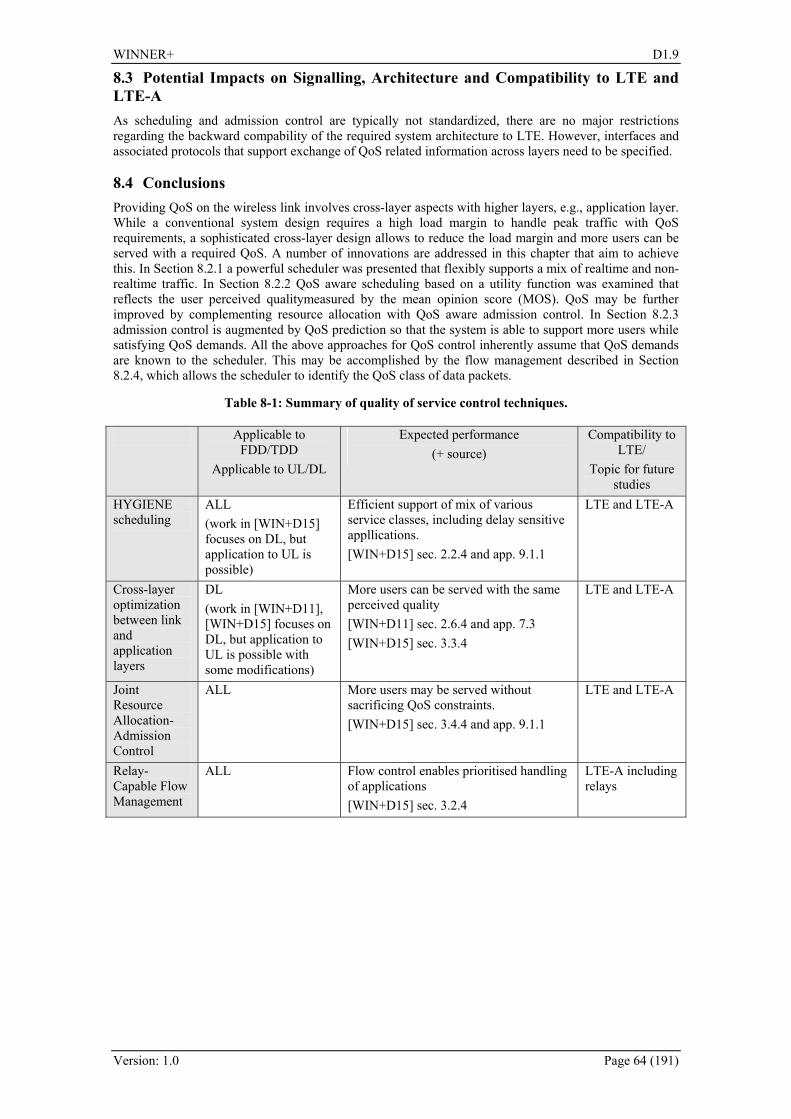
WINNER+ D1.9
Version: 1.0 Page 64 (191)
8.3 Potential Impacts on Signalling, Architecture and Compatibility to LTE and LTE-A As scheduling and admission control are typically not standardized, there are no major restrictions regarding the backward compability of the required system architecture to LTE. However, interfaces and associated protocols that support exchange of QoS related information across layers need to be specified.
8.4 Conclusions Providing QoS on the wireless link involves cross-layer aspects with higher layers, e.g., application layer. While a conventional system design requires a high load margin to handle peak traffic with QoS requirements, a sophisticated cross-layer design allows to reduce the load margin and more users can be served with a required QoS. A number of innovations are addressed in this chapter that aim to achieve this. In Section 8.2.1 a powerful scheduler was presented that flexibly supports a mix of realtime and non-realtime traffic. In Section 8.2.2 QoS aware scheduling based on a utility function was examined that reflects the user perceived qualitymeasured by the mean opinion score (MOS). QoS may be further improved by complementing resource allocation with QoS aware admission control. In Section 8.2.3 admission control is augmented by QoS prediction so that the system is able to support more users while satisfying QoS demands. All the above approaches for QoS control inherently assume that QoS demands are known to the scheduler. This may be accomplished by the flow management described in Section 8.2.4, which allows the scheduler to identify the QoS class of data packets.
Table 8-1: Summary of quality of service control techniques.
Applicable to FDD/TDD
Applicable to UL/DL
Expected performance (+ source)
Compatibility to LTE/
Topic for future studies
HYGIENE scheduling
ALL (work in [WIN+D15] focuses on DL, but application to UL is possible)
Efficient support of mix of various service classes, including delay sensitive appllications. [WIN+D15] sec. 2.2.4 and app. 9.1.1
LTE and LTE-A
Cross-layer optimization between link and application layers
DL (work in [WIN+D11], [WIN+D15] focuses on DL, but application to UL is possible with some modifications)
More users can be served with the same perceived quality [WIN+D11] sec. 2.6.4 and app. 7.3 [WIN+D15] sec. 3.3.4
LTE and LTE-A
Joint Resource Allocation-Admission Control
ALL More users may be served without sacrificing QoS constraints. [WIN+D15] sec. 3.4.4 and app. 9.1.1
LTE and LTE-A
Relay-Capable Flow Management
ALL Flow control enables prioritised handling of applications [WIN+D15] sec. 3.2.4
LTE-A including relays

WINNER+ D1.9
Version: 1.0 Page 65 (191)
9. Coordinated Multipoint
9.1 Introduction Future cellular networks will need to provide high data rate services for a large number of users, which requires a high spectral efficiency over the entire cell area. In order to achieve this, it is important that the radio interface is robust to interference and in particular inter-cell interference (ICI) which appears when the same radio resources are re-used in different cells in an uncoordinated way. Naturally, ICI particularly degrades the performance of users located in the cell edge areas, which creates a performance discrepancy between cell edge and inner cell users. One possible means to alleviate this performance discrepancy is to employ Coordinated Multi Point (CoMP) transmission and reception, which refers to a system where the transmission and/or reception at multiple, geographically separated antenna sites is dynamically coordinated in order to improve system performance. The CoMP framework encompasses all the system designs allowing tight coordination between multiple radio access points for transmission and/or reception. Three types of coordinated entities can be considered, as stated in [WIN+D14] and depicted in 263HFigure 9-1:
• Remote radio units (RRU); • Cells, which involve intra-BS or inter-BS coordination; • Relay nodes (RNs; see chapter 264H5 for details).
Figure 9-1: Different instances of systems able to implement CoMP.
CoMP schemes are studied in literature both for downlink and uplink, aiming to assess the performances of coordination in transmission and reception. In WINNER+ the main focus is on downlink coordination and at a high level, downlink coordination schemes can be divided into two categories (this classification mostly follows the one 3GPP adopted in the study item for Long Term Evolution Advanced (LTE-A) [3GPP36814]):
• Coordinated scheduling and/or beamforming • Joint processing/transmission
In the first category data to a single user equipment (UE) is instantaneously transmitted from one of the transmission points, and scheduling decisions and/or generated beams are coordinated across cells in order to control the created interference. The main advantages of these schemes compared to schemes involving joint processing/transmission are that the requirements on the coordination links and on the backhaul are significantly reduced, since typically
• only information on scheduling decisions and/or generated beams (and information needed for their generation) need to be coordinated, and
• user data do not need to be made available at the coordinated transmission points, since there is only one serving transmission point for one particular UE.
In the second category, joint processing/transmission, data to a single UE is simultaneously transmitted from multiple transmission points, e.g. to (coherently or non-coherently) improve the received signal quality and/or cancel actively interference for other UEs. This category of schemes puts higher requirements on the coordination links and the backhaul since user data need to be made available at multiple coordinated transmission points. The amount of data to be exchanged over the coordination links is also larger, e.g. channel knowledge and computed transmission weights. On the other hand, the joint
WINNER+ D1.9
Version: 1.0 Page 66 (191)
processing CoMP could ensure more significant gains with respect to coordinated scheduling/beamforming in terms of average and cell-edge users throughput. Either in coordinated beamforming and in joint processing case, the notion of clustering, i.e. the selection process of a set of coordinated cells, is a key issue to improve the achievable performances. The concept of clustering, as used in WINNER+, is closely related to those of CoMP cooperative sets and/or measurement sets as defined in 3GPP [3GPP36814].
9.2 Proposed Innovations In this section an overview of the main innovations introduced in WINNER+ as far as CoMP is concerned is presented, encompassing architectures and clustering issues, joint processing solutions and coordinated beamforming activities.
9.2.1 Architectures and clustering The introduction of CoMP implies a considerable impact on the architecture of the radio system that will make use of it, and the feasibility of this solution is then widely studied in the research community. Besides, if a CoMP scheme is adopted, efficient cells and users selection scheme are mandatory issues to be analyzed. Coordination between neighbouring base stations is a very promising way to reduce inter-cell interference in the network, either in the uplink (coordinated reception) or in the downlink (coordinated transmission). Although different time scales are possible for the coordination, the most efficient schemes require the information needed for scheduling to be available at each coordinated BS, which calls for very low-latency (on the order of the millisecond) information exchanges between coordinated nodes, or between the UE and all the coordinated nodes. Two extreme approaches can be distinguished regarding how to make this information timely available at distant BSs: centralised and decentralised coordination. These approaches are described in the following in the most general case where joint processing is performed across various BSs. Nevertheless, these approaches also apply in the simpler case of coordinated scheduling/beamforming. Otherwise, an architecture that could enable an efficient digital RoF based CoMP approach has been introduced in WINNER+ (see [WIN+D14]), where M Remote Units (RU) are connected via digital/optical fiber in daisy chain to the Base-Band modules of the Base Station (Central Unit, CU). The Central Unit is able to transmit/receive multiple antenna carriers and each RU has multiple antenna elements forming an antenna array. The RoF based architecture easily paves the way both to inter site cooperation and to coordination within the same site as well, referring in the latter case to CoMP schemes encompassing the different sectors of the same site. This proposed architecture can include newly-introduced so-called reconfigurable antennas in the remote antenna units, i.e. system capable of making digital beamforming so as to optimize the beam for the cell. Reconfigurable antennas can be effectively used in cellular network planning. In fact by means of an optimization procedure, it is possible to dynamically define a set of beam patterns that the reconfigurable antennas can radiate in order to maximize several output parameters. In any case, whatever the chosen architecture, studies have been performed on how the distributions of users in a given ideal cellular layout could improve the performances with respect to an uncoordinated case. For details see Appendix B.4 in [WIN+D14] and paragraph 2.1 in [WIN+D18]. On the other hand, the selection of users among the coordinated cells is another problem focused on in WINNER+: “CoMP” means that several base stations share some knowledge about users but, as the number of users and BSs increase, the signaling overhead required for the inter-base information exchange and the amount of feedback needed from the users also increase. Therefore, cooperation should be restrained to a limited number of BSs. To achieve this goal, the network is thus divided into clusters of cooperative cells. Cluster selection is obviously a key to cooperation algorithms performance and has been widely studied in WINNER+. Cluster formation may be static, if the clusters remain fixed in time, or dynamic. Selection may be performed in a network-centric manner, where a cell is coordinated with specific cells in the cluster, whatever the UE to be served, or in a per-user way, i.e. in a user-centric manner.
9.2.2 Joint processing Joint transmission or joint processing between base stations (BSs) has been identified in WINNER+ as one of the key techniques for mitigating inter-cell interference in future broadband communication systems. In this approach, a group of BSs acts as a single distributed antenna array and hence, data to a single user is simultaneously transmitted from more than one BS. Joint processing CoMP generally involves coherent joint signal processing relying on instantaneous channel state information (CSI) enabling multi-cell multi-user precoding techniques like linear beamforming. Therefore, the same number of users can be served simultaneously on one time-frequency resource as in single-cell transmission, while the interference between the users is minimised. In addition to linear techniques such as Zero
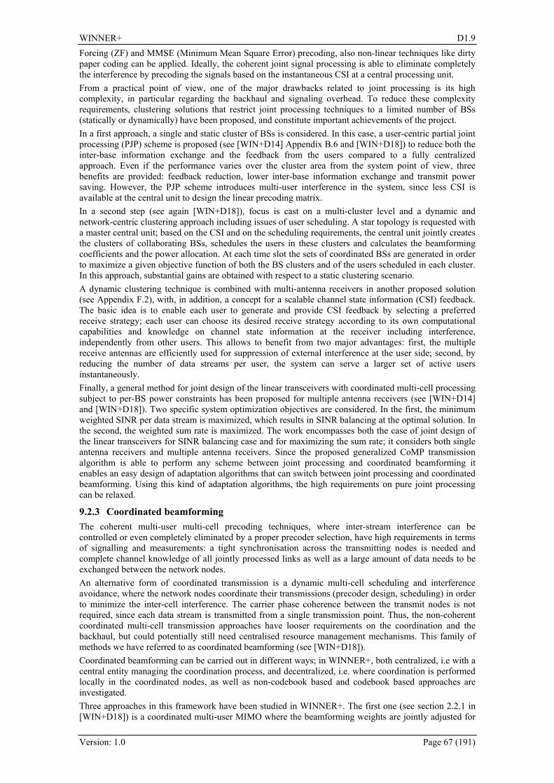
WINNER+ D1.9
Version: 1.0 Page 67 (191)
Forcing (ZF) and MMSE (Minimum Mean Square Error) precoding, also non-linear techniques like dirty paper coding can be applied. Ideally, the coherent joint signal processing is able to eliminate completely the interference by precoding the signals based on the instantaneous CSI at a central processing unit. From a practical point of view, one of the major drawbacks related to joint processing is its high complexity, in particular regarding the backhaul and signaling overhead. To reduce these complexity requirements, clustering solutions that restrict joint processing techniques to a limited number of BSs (statically or dynamically) have been proposed, and constitute important achievements of the project. In a first approach, a single and static cluster of BSs is considered. In this case, a user-centric partial joint processing (PJP) scheme is proposed (see [WIN+D14] Appendix B.6 and [WIN+D18]) to reduce both the inter-base information exchange and the feedback from the users compared to a fully centralized approach. Even if the performance varies over the cluster area from the system point of view, three benefits are provided: feedback reduction, lower inter-base information exchange and transmit power saving. However, the PJP scheme introduces multi-user interference in the system, since less CSI is available at the central unit to design the linear precoding matrix. In a second step (see again [WIN+D18]), focus is cast on a multi-cluster level and a dynamic and network-centric clustering approach including issues of user scheduling. A star topology is requested with a master central unit; based on the CSI and on the scheduling requirements, the central unit jointly creates the clusters of collaborating BSs, schedules the users in these clusters and calculates the beamforming coefficients and the power allocation. At each time slot the sets of coordinated BSs are generated in order to maximize a given objective function of both the BS clusters and of the users scheduled in each cluster. In this approach, substantial gains are obtained with respect to a static clustering scenario. A dynamic clustering technique is combined with multi-antenna receivers in another proposed solution (see Appendix 265HF.2), with, in addition, a concept for a scalable channel state information (CSI) feedback. The basic idea is to enable each user to generate and provide CSI feedback by selecting a preferred receive strategy; each user can choose its desired receive strategy according to its own computational capabilities and knowledge on channel state information at the receiver including interference, independently from other users. This allows to benefit from two major advantages: first, the multiple receive antennas are efficiently used for suppression of external interference at the user side; second, by reducing the number of data streams per user, the system can serve a larger set of active users instantaneously. Finally, a general method for joint design of the linear transceivers with coordinated multi-cell processing subject to per-BS power constraints has been proposed for multiple antenna receivers (see [WIN+D14] and [WIN+D18]). Two specific system optimization objectives are considered. In the first, the minimum weighted SINR per data stream is maximized, which results in SINR balancing at the optimal solution. In the second, the weighted sum rate is maximized. The work encompasses both the case of joint design of the linear transceivers for SINR balancing case and for maximizing the sum rate; it considers both single antenna receivers and multiple antenna receivers. Since the proposed generalized CoMP transmission algorithm is able to perform any scheme between joint processing and coordinated beamforming it enables an easy design of adaptation algorithms that can switch between joint processing and coordinated beamforming. Using this kind of adaptation algorithms, the high requirements on pure joint processing can be relaxed.
9.2.3 Coordinated beamforming The coherent multi-user multi-cell precoding techniques, where inter-stream interference can be controlled or even completely eliminated by a proper precoder selection, have high requirements in terms of signalling and measurements: a tight synchronisation across the transmitting nodes is needed and complete channel knowledge of all jointly processed links as well as a large amount of data needs to be exchanged between the network nodes. An alternative form of coordinated transmission is a dynamic multi-cell scheduling and interference avoidance, where the network nodes coordinate their transmissions (precoder design, scheduling) in order to minimize the inter-cell interference. The carrier phase coherence between the transmit nodes is not required, since each data stream is transmitted from a single transmission point. Thus, the non-coherent coordinated multi-cell transmission approaches have looser requirements on the coordination and the backhaul, but could potentially still need centralised resource management mechanisms. This family of methods we have referred to as coordinated beamforming (see [WIN+D18]). Coordinated beamforming can be carried out in different ways; in WINNER+, both centralized, i.e with a central entity managing the coordination process, and decentralized, i.e. where coordination is performed locally in the coordinated nodes, as well as non-codebook based and codebook based approaches are investigated. Three approaches in this framework have been studied in WINNER+. The first one (see section 2.2.1 in [WIN+D18]) is a coordinated multi-user MIMO where the beamforming weights are jointly adjusted for

WINNER+ D1.9
Version: 1.0 Page 68 (191)
all transmission points in the coordination cluster in order to minimize the caused interference. The second concept is a distributed solution for the coordinated multi-cell multi-antenna minimum power beamformer design problem with single-antenna users where the minimum power beamformers are obtained locally at each BS relying on limited backhaul information exchange between adjacent BSs. Hence, this concept operates in a decentralized manner in contrast to the previous concept. The third concept studied in WINNER+ is based on the codebook-based precoding which already exists in LTE Rel-8. The main idea in this concept is to make use of a report from the UE of a Precoding Matrix Index (PMI) indicating either the most interfering (MI) beam, or the least interfering (LI) beam received from an interfering cell (see also paragraph 266H7.3.1 for a similar method based on the best/worst companion index). The serving cell communicates to coordinated interfering cells the time-frequency resources that will be used for transmission to the scheduled UE, together with the MI/LI-PMI reported by this UE. These pieces of information will then act as constraints for the coordinated cells' schedulers, which should try as much as possible to avoid/favour the reported MI/LI-PMI on the associated resources for their own transmission.
9.3 Expected Performance of Innovations
9.3.1 Joint processing performance The above mentioned joint processing solutions are assessed by independent evaluations by means of proper comparisons to reference scenarios, not disregarding the added complexity they carry on the overall system characteristics. A full overview of the achieved results of the user centric partial joint processing (PJP) and related techniques is reported in Appendix 267HF.1. In 268HFigure 9-2 the average sum-rate per cell obtained by the different transmission schemes is plotted when moving away from one of the BSs of the cluster. In this case, M = 6 users are placed in each position. The PJP plots stand for active set threshold values of 10, 20 or 40 dB, respectively. Results for the conventional single-BS transmission scheme, `1BS', are also included as a base-line. For low mobility users, the backhaul overhead related to exchanging the user data between the BSs is higher than the overhead required for exchanging the channel coefficients. Then, the combined value of backhaul exchange and feedback from the users can be roughly estimated by means of the average number of BSs that are transmitting to a user. In the CJP and DJP schemes, this parameter remains fixed regardless of the location of the users in the cluster area. However, for the PJP scheme, that number depends both on the active set threshold value and the user position over the cluster area. Different metrics and more results are in Appendix 269HF.1.
Figure 9-2: PJP joint processing, average sum rate per cell (left) and average number of BSs per user (right).
As far as the dynamic clustering approach is concerned, a system simulator has been developed with 19 single antenna BSs and wraparound, 30 users per BS, edge-of-cell SNR of 15dB. Each single-antenna user is dropped with uniform probability inside each cell. Fairness is guaranteed by a proportional fairness scheduler. The reference SNR is defined as the SNR at the cell vertex. The channel has been modeled considering Rayleigh and path loss effect (with path loss exponent equal to 4.5). In 270HTable 9-1 the performance of the proposed algorithm is summarized respectively in terms of average rate per cell and cell-edge rate (5% tile) for a cluster size of 10 BSs, which corresponds to a 50% reduction in the number of BSs sharing the data of the users scheduled for transmission in a given frame compared to full network coordination (full CoMP). Four different techniques are compared: non-cooperating BSs, static coordination, i.e. clusters of cooperating BSs are kept fixed during all the simulation and in each cluster

WINNER+ D1.9
Version: 1.0 Page 69 (191)
the users are selected for transmission using a proportional fair scheduler (hence the increased cell-edge user throughput with respect to the average one), dynamic coordination and full coordination, i.e. all the N BSs cooperate together and up to N users are scheduled for transmission in each frame with a proportional fair approach.
Table 9-1: Performance of joint processing dynamic clustering approach.
For the case of joint processing with scalable CSI feedback a system simulator has been developed with 57 multi-antenna BS sectors and a wraparound using 3GPP's extended spatial channel model (SCME). A set of active multi-antenna terminals is uniformly distributed in the i-th cluster of the cellular environment. All users are connected to a master BS. Further, we emulate a cluster selection which is user-centric and dynamic over frequency. Results are provided for different cluster sizes (1; 2; 3). In 271HFigure 9-3, the performance of the concept is demonstrated with respect to the spectral efficiency per sector within the cluster. For reference purpose, we provide results for SISO and MIMO 2x2 (static DFT) without any CoMP transmission. For the static DFT-precoded system, we perform simultaneous multi-user service to 2 users with a fixed or dynamic stream assignment. For K = 3 BSs in the cluster, this transmission strategy increases the median sector and cell-edge user throughput by a factor of 4.2 and 13, respectively, compared to the non-coordinated SISO setup.
Figure 9-3: Sector spectral efficiency of the proposed joint processing method with scalable CSI feedback.
Performance of the generalized method for joint design of linear transceivers with CoMP transmission is evaluated in detail in [WIN+D18]. 272HTable 9-2 presents the ergodic sum rate of users at the cell edge for systems with sum rate maximization algorithm at 20 dB single link signal to noise ratio (SNR). The single link SNR denotes the average SNR at the receiver, and the received signal strength is based on the maximum transmit power and the pathloss. Coherent multi-cell beamforming, coordinated beamforming with optimal beam allocation (exhaustive search), non-coordinated beamforming with optimal beam allocation (exhaustive search) are compared. The inter-cell interference is neglected in the precoder design.
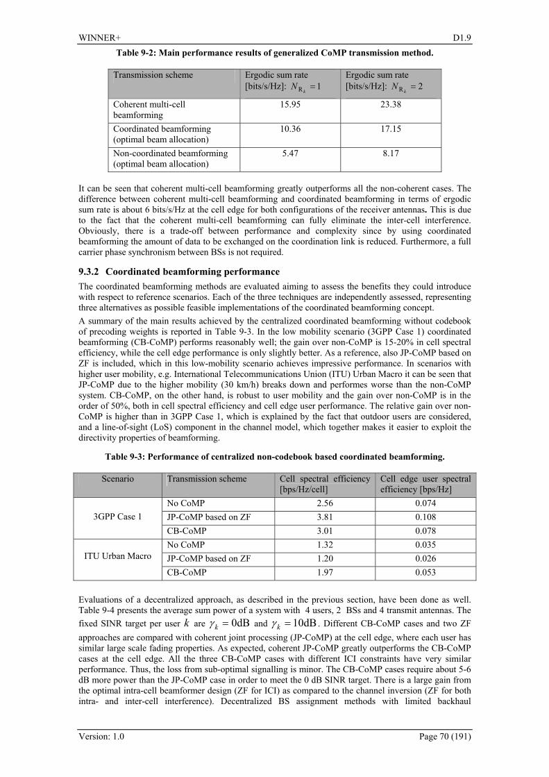
WINNER+ D1.9
Version: 1.0 Page 70 (191)
Table 9-2: Main performance results of generalized CoMP transmission method.
Transmission scheme Ergodic sum rate [bits/s/Hz]: 1R =
kN
Ergodic sum rate [bits/s/Hz]: 2R =
kN
Coherent multi-cell beamforming
15.95 23.38
Coordinated beamforming (optimal beam allocation)
10.36 17.15
Non-coordinated beamforming (optimal beam allocation)
5.47 8.17
It can be seen that coherent multi-cell beamforming greatly outperforms all the non-coherent cases. The difference between coherent multi-cell beamforming and coordinated beamforming in terms of ergodic sum rate is about 6 bits/s/Hz at the cell edge for both configurations of the receiver antennas. This is due to the fact that the coherent multi-cell beamforming can fully eliminate the inter-cell interference. Obviously, there is a trade-off between performance and complexity since by using coordinated beamforming the amount of data to be exchanged on the coordination link is reduced. Furthermore, a full carrier phase synchronism between BSs is not required.
9.3.2 Coordinated beamforming performance The coordinated beamforming methods are evaluated aiming to assess the benefits they could introduce with respect to reference scenarios. Each of the three techniques are independently assessed, representing three alternatives as possible feasible implementations of the coordinated beamforming concept. A summary of the main results achieved by the centralized coordinated beamforming without codebook of precoding weights is reported in 273HTable 9-3. In the low mobility scenario (3GPP Case 1) coordinated beamforming (CB-CoMP) performs reasonably well; the gain over non-CoMP is 15-20% in cell spectral efficiency, while the cell edge performance is only slightly better. As a reference, also JP-CoMP based on ZF is included, which in this low-mobility scenario achieves impressive performance. In scenarios with higher user mobility, e.g. International Telecommunications Union (ITU) Urban Macro it can be seen that JP-CoMP due to the higher mobility (30 km/h) breaks down and performes worse than the non-CoMP system. CB-CoMP, on the other hand, is robust to user mobility and the gain over non-CoMP is in the order of 50%, both in cell spectral efficiency and cell edge user performance. The relative gain over non-CoMP is higher than in 3GPP Case 1, which is explained by the fact that outdoor users are considered, and a line-of-sight (LoS) component in the channel model, which together makes it easier to exploit the directivity properties of beamforming.
Table 9-3: Performance of centralized non-codebook based coordinated beamforming.
Scenario Transmission scheme Cell spectral efficiency [bps/Hz/cell]
Cell edge user spectral efficiency [bps/Hz]
No CoMP 2.56 0.074 JP-CoMP based on ZF 3.81 0.108
3GPP Case 1
CB-CoMP 3.01 0.078 No CoMP 1.32 0.035 JP-CoMP based on ZF 1.20 0.026
ITU Urban Macro
CB-CoMP 1.97 0.053 Evaluations of a decentralized approach, as described in the previous section, have been done as well. 274HTable 9-4 presents the average sum power of a system with 4 users, 2 BSs and 4 transmit antennas. The fixed SINR target per user k are dB0=kγ and dB10=kγ . Different CB-CoMP cases and two ZF approaches are compared with coherent joint processing (JP-CoMP) at the cell edge, where each user has similar large scale fading properties. As expected, coherent JP-CoMP greatly outperforms the CB-CoMP cases at the cell edge. All the three CB-CoMP cases with different ICI constraints have very similar performance. Thus, the loss from sub-optimal signalling is minor. The CB-CoMP cases require about 5-6 dB more power than the JP-CoMP case in order to meet the 0 dB SINR target. There is a large gain from the optimal intra-cell beamformer design (ZF for ICI) as compared to the channel inversion (ZF for both intra- and inter-cell interference). Decentralized BS assignment methods with limited backhaul

WINNER+ D1.9
Version: 1.0 Page 71 (191)
information exchange in combination with decentralized beamforming approaches were introduced as well (see Appendix 275HF.3 for details).
Table 9-4: Performance of decentralized non-codebook based coordinated beamforming.
Transmission scheme Average sum power (dB): dB0=kγ
Average sum power (dB): dB10=kγ
Coherent JP-CoMP -1.45 9.71 CB-CoMP: user-specific ICI constraint 3.90 19.44 CB-CoMP: BS-specific ICI constraint 4.20 19.96 CB-CoMP: common ICI constraint 4.88 23.96 ZF for ICI 8.92 24.81 ZF for intra- and inter-cell interference 15.21 25.21 At last, a decentralized codebook-based coordinated beamforming approach has been evaluated (see 276HTable 9-5). The considered scenario is similar to 3GPP case 1 with full buffer traffic model. A simplified snapshot/quasi-static based system-level simulator has been used (see [WIN+D18] for a full description of the simulation set-up). Coordinated beamforming with the proposed scheme provides only moderate gains in cell-edge performance compared to non-coordinated beamforming in a realistic coordination setup (3 coordinated cells, no central control entity): +13% for 1 MI-PMI and +19% for 3 MI-PMI. No significant change in cell throughput is observed. Note that these results are only preliminary, and in particular use a very simple scheduler.
Table 9-5: Performance of decentralized codebook based coordinated beamforming.
Transmission scheme Cell spectral efficiency [bps/Hz/cell]
Cell edge user spectral efficiency [bps/Hz]
No coordination 4.49 0.16 CB-CoMP with 1 MI-PMI 4.43 (-1%) 0.18 (+13%) CB-CoMP with 3 MI-PMI 4.62 (+3%) 0.19 (+18%)
9.4 Practical implementation in a trial environment The efficiency of CoMP techniques on the field is yet to be proven. A trial is currently ongoing aiming to validate the CoMP concept, wich implements the joint processing method based on scalable CSI feedback. Details on the method are given in previous paragraph 277H9.2.2 and 278H9.3.1 and a full description of the trial as well is reported in Appendix 279HF.2. The distributed joint processing (DJP) has been implemented in the downlink on top of an existing real-time FDD LTE trial system. This extension is limited to two coherently cooperating base stations and two terminals operating at 2.68 GHz in 20 MHz bandwidth in the downlink. Base stations and terminals have two antennas each, hence the whole setup is a virtual 4x4 MIMO link with cooperation enabled at the transmit side. Enabling features for DJP such as distributed synchronization using GPS, cell- and user-specific pilots, feedback of multi-cell channel state estimates over the uplink as well as synchronous data exchange over a standard Ethernet link between the base stations have been implemented and tested. Interference-limited transmission experiments have then been conducted step by step, starting over channels measured in real deployment scenarios and played back in a real-time channel emulator, followed by over-the-air measurements in a lab. The setup is extended currently to enable outdoor field trials. In all experiments, impressive gains compared to interference-limited operation have been observed, however it is also noticed that synchronization is feasible but challenging in general for the distributed joint processing approach. Altogether, even if these trials have not yet been fully finished at the time of this writing, we can already conclude that the distributed joint processing approach is technically feasible and that the great performance benefits of CoMP transmission in the downlink can also be realized on the field using advanced cellular system technology. Already with a simple linear CoMP precoder, a significant fraction of the capacity of an isolated cell can be achieved while facing strong inter-cell interference.

WINNER+ D1.9
Version: 1.0 Page 72 (191)
9.5 Potential Impacts on Signalling In order to realize CoMP, there are some potential impacts on the signalling, e.g. transmit control signalling, pilots for demodulation and CSI acquisition, feedback design etc. In the case of coordinated beamforming schemes, the transmission to a certain UE takes place from one of the transmission points (typically a cell), which means that from a control signalling perspective there is no specific impact; scheduling assignments, etc., are as usual transmitted from the serving cell. The only difference compared to a non-coordinated system is that information on scheduling decisions and /or generated beams (and information needed for their generation, including CSI acquisition in some possible approaches) need to be coordinated. This can be done in different ways, where the most straight-forward would be that each UE reports to its serving cell, and then it is an architectural question how to communicate among the coordinated BSs, which will be discussed in the next section. The joint processing schemes cause more implications on the signalling. Since the transmission to a certain UE takes place from several cells/sites, this affects the type of demodulation reference signals. In case of cell-specific demodulation reference signals, there is a need to signal the transmission scheme to the UE. Therefore UE specific demodulation reference signals might be preferred, since in that case the reference signals are subject to the same precoding as the data, which means that the UE does not have to care from which cells/sites the transmission originates. Perhaps the main challenge for joint processing is CSI acquisition and feedback, since short-term CSI of high accuracy for all links involved in the coordination typically is required for this kind of schemes. Methods for achieving this are thoroughly discussed in chapter 280H7 above; the main extension when applying this to CoMP is how to communicate among the coordinated BSs. This is, however, rather an architectural question than a signalling aspect; hence it will be discussed in the next section.
9.6 Potential Impacts on Architecture As can be imagined, and also already touched upon in the sections above, CoMP can have significant impacts on the architecture. This is since information need to be communicated and coordinated between the cells/sites involved in the coordination. Although different time scales are possible for the coordination, the most efficient schemes require the information needed for scheduling to be available at each coordinated BS, which calls for very low-latency (on the order of the millisecond) information exchanges between coordinated nodes. Two extreme approaches can be distinguished regarding how to make this information timely available at distant BSs: centralised and decentralised coordination. In the case of centralised coordination, a central unit is responsible for all the coordination in terms of scheduling and also beamforming weight generation (in the case of coordinated beamforming) as well as full baseband processing (in case of joint processing). All the transmission points communicate with the central unit in terms of channel knowledge for precoder calculation, and the central unit communicates the generated precoders and scheduling decisions to the transmission points. This put high requirements on the backhaul in terms of capacity and latency, and one possible implementation of it is a base station with remote units (RU) connected over RoF links as described in section 281H9.2.1. In the decentralised coordination the coordinated BSs communicate directly with each other, e.g. over the X2 interface. Joint processing type of schemes typically require centralised coordination, in order to effectively realise the joint baseband processing, but also decentralised implementations are possible, see e.g. appendix 282HF.2. Regardless the assumed architecture, the backhaul requirements are high in terms of capacity and latency, since user data has to be made available at all transmission points. Coordinated beamforming can, as already discussed in section 283H9.2.3, be implemented in both centralised and decentralised architectures. Coordinated beamforming typically have lower requirements in terms of capacity of the coordination links than joint processing, and thus might require less investments from the operator.
9.7 Compatibility to LTE and LTE-Advanced CoMP is one of the features that was considered by 3GPP for LTE-Advanced in the Study Item (SI) phase (see [3GPP36814]). It did, however, not make it into the LTE release 10 Work Item (WI) phase, but will instead potentially be further studied for future releases of LTE. Within the SI, several structuring decisions were made regarding the support of CoMP. As in WINNER+, the techniques have been divided into two main categories:
• Coordinated scheduling and/or beamforming (where the data is transmitted from a single point) • Joint processing (where the data is transmitted from multiple points)

WINNER+ D1.9
Version: 1.0 Page 73 (191)
Regardless of the above category, it was decided in 3GPP that the UE will receive its control channel (PDCCH, Physical Downlink Control Channel) carrying e.g. the scheduling information, from a single cell. This cell is called the serving cell, and is the cell the UE would be served by in the case of a single-cell transmission. In addition, the UE may not be aware of the cells it is receiving data from. It was also decided that the reference signals used for data transmission in CoMP will be UE-specific. This means that the reference signals experience the same precoding as the data. In that case, the UE does not need to know how many cells are involved in the transmission, since it only sees one composite channel formed by the sum of the channels to all the involved eNodeBs. In addition, the eNodeB does not need to signal to the UE what are the precoding weights used at the transmitter, which allows any precoding schemes to be supported, provided the necessary CSI can be acquired or fed back. Note that multiple layers (up to 8 in the DL) will be supported by the defined reference signal framework. The reference signal for CSI (e.g. PMI and CQI) estimation will be cell-specific, in order to allow the UE to estimate and report its CSI to various neighbouring cells. Furthermore, 3GPP (see [3GPP36814]) has defined CoMP sets:
• CoMP cooperating set: Set of (geographically separated) points directly or indirectly participating in PDSCH (Physical Downlink Shared Channel, the DL data channel) transmission to UE.
• CoMP transmission point(s): point or set of points actively transmitting PDSCH to UE • CoMP measurement set: set of cells about which channel state/statistical information related to
their link to the UE is reported. The CoMP sets are to a large extent related to the clustering approaches studied in WINNER+, see e.g. section 284H9.2.1. Note however that 3GPP so far has not decided any details on how the CoMP sets are formed. The main remaining areas in the 3GPP CoMP framework are the measurements needed at the UE and the feedback design principles. These items aim at supplying CSI to the transmitter (at least in FDD), and possibly at facilitating the identification of the transmission points to be coordinated for one given UE, i.e. the formation of CoMP sets. Most of the discussions have focussed on the CoMP-supporting feedback design. Two main types of feedback have been identified:
• Explicit feedback: channel as observed by the receiver, without assuming any transmission or receiver processing (e.g. channel impulse response, channel covariance matrix)
• Implicit feedback: feedback mechanisms that use hypotheses of different transmission and/or reception processing, e.g., CQI/PMI/RI as used already in LTE release 8.
In addition, UE transmission of UL sounding reference signal (SRS) can be used for CSI estimation at multiple cells, exploiting channel reciprocity (both for FDD and TDD). Enhanced SRS schemes may be considered for this purpose. If new feedback will be needed, strive for scalable feedback for different CoMP categories (CB and JP) if both CoMP categories were supported. Feedback scalability means that a feedback in support of JP-CoMP is a superset of a feedback in support of CB-CoMP. A UE feedback in support of a CoMP transmission category is such that it also enables the network to dynamically switch to single-point transmission for this CoMP transmission category. Individual per-cell feedback is the baseline for schemes that need feedback. Here, per-cell feedback only relates to the content of the feedback. In other words, per-cell feedback does not mean the feedback has to be transmitted to each corresponding cell: the feedback related to each individual cooperating cell could be also transmitted only to the serving cell. The baseline is that UE CoMP feedback reports target the serving cell. In this case, the reception of UE reports at cells other than the serving cell is a network implementation choice. The CSI-RS (i.e. the reference signals used to measure the CSI) will be designed in Rel-10 to allow accurate inter-cell measurements, thus providing the UE with the capability of acquiring CSI from neighbouring cells in future LTE releases. To summarize, a CoMP framework has been defined in 3GPP, but several issues are still unclear and remain to be studied for releases beyond LTE release 10 (LTE-Advanced). Regarding the CoMP techniques being studied in WINNER+, it can be envisioned that at least the coordinated beamforming ones can be supported with only minor additions to LTE release 8, if any. When it comes to joint processing techniques, more support is likely to be needed to be added in the standard, e.g. mechanisms for clustering. These are part of the CoMP framework that was defined in the LTE-Advanced SI. In particular, most of the joint processing techniques require short-term CSI which in the FDD case would mean explicit feedback, which is still an open issue in 3GPP. Hence, these are the areas that need to be adressed in order to provide standard support for CoMP in future releases of LTE beyond release 10 (LTE-Advanced). Note however that proprietary implementation, relying e.g. on the (long-term) channel

WINNER+ D1.9
Version: 1.0 Page 74 (191)
reciprocity between UL and DL, may be possible within the Rel-10 specifications, even though specific standard support is not provided.
9.8 Conclusions Coordinated MultiPoint transmission is a topic widely studied and analyzed in WINNER+, and was also one of the most discussed issues in the 3GPP Study Item for LTE Advanced, even though it did not make it into the Work Item phase. In this section the work carried on in the framework of WINNER+ project regarding CoMP has been presented, encompassing the suggested approaches and the related main area of interest and discussion. Consisting in a possible and extensive network innovation, CoMP is deemed to have a significant impact on the RAN architecture. Some proposals, either centralised or decentralised, have been studied to introduce CoMP on top of LTE-A system as seamlessly as possible. On this issue, moreover, the proposal of creating cluster of cooperating cells is a distinctive contribution of the project to the effective implementation of such techniques. Furthermore, WINNER+ introduced the intra-eNB CoMP with RoF architecture as a viable solution, much easier to implement due to the fact that no backhaul impact is foreseen in this case. Like in the 3GPP framework, WINNER+ has cast attention to both joint processing and coordinated beamforming solutions for CoMP. The former approach is the most challenging, requiring huge exchange of data and maybe also an enhanced interface architecture among cooperating nodes. At the moment, then, many different proposals about joint processing are being studied and no final and definitive choice on which of them is the most feasible has been taken. The latter approach is more straightforward, even if performances, especially if compared to joint processing, are somewhat poorer and less encouraging. Anyway, the relative easy implementation of some coordinated beamforming solutions and the more seamless application to current network architectures let coordinated beamforming methods, especially for intra-eNB scenarios, be considered as the likely first step towards CoMP in future networks.
Table 9-6: Summary of coordinated multipoint techniques.
Applicable to FDD/TDD
Applicable to UL/DL
Expected performance (+ source)
Compatibility to LTE/
Topic for future studies
RAN Architecture for CoMP
ALL Enabler of CoMP solutions (D1.4)
Proposed for LTE-A
To be further studied
Coordinated beamforming
FDD/TDD, DL Increase cell edge and cell average performance, in a
centralised/decentralised solution (D1.8, partially D1.4)
Proposed for LTE-A
To be further studied
Joint processing
FDD/TDD, DL Increase of overall performance (cell throughput, ergodic sum rate, spectral
efficiency,…) (D1.4 and D1.8)
Proposed for LTE-A
To be further studied
First practical trial
implementation
FDD/TDD, DL Practical implementation of first CoMP solutions
(D1.9, appendix F2)
Trial still ongoing

WINNER+ D1.9
Version: 1.0 Page 75 (191)
10. Other techniques In this chapter we briefly highlight two techniques that have been proposed within the project, but that were classified as outside the scope of the previous chapters.
10.1 Device-to-device communication as an underlay to an LTE network Device to device (D2D) communication as an underlay to the cellular network operation was proposed in [WIN+D13] chapter 2. The BS is in control of the resources that are used by UE1 and UE2 for D2D communication, as shown in 285HFigure 10-1. Further, the BS can set the maximum transmit power of the D2D transmitters to limit the interference to the cellular network.
Figure 10-1: Device to device communication in parallel to the cellular communication. Green arrows indicate the wanted signals and red arrows the interference.
The D2D concept was first investigated as an enabler for supporting new local special services like a media server during a rock concert without need for an additional air interface in the UEs and with interference control in the cellular network. Then, the D2D concept was investigated as a means to maximize the overall throughput in the cell. An LTE network in TDD operation was assumed. The throughput was evaluated in an isolated cell scenario under different resource allocation strategies between the D2D and the cellular network users. The study shows that without constraints an up to 7-fold increase in cell throughput can be achieved. The gains are lower when offering a guaranteed rate to the cellular users. Nevertheless the cell throughput can still be doubled or even increased 3 times depending on the D2D link distance. Thus, the single cell studies showed that D2D communication is a promising technology to increase the sum rate in a cellular network. Future work is needed to study D2D communication as an underlay to an LTE network in an interference limited local area scenario. In particular procedures that allow the BS to limit the interference from D2D communication to the cellular network would be needed, and such procedures would impact compatibility with LTE and LTE Advanced.
10.2 Power efficient uplink transmission In [WIN+D15] chapter 6 a power efficient uplink transmission scheme denoted Continuous Phase Modulated Single Carrier Frequency Division Multiple Access (CPM-SC-FDMA) scheme was proposed. A Continuous Phase Modulated (CPM) signal is sampled and the samples are sent as the data symbols to a Single Carrier Frequency Division Multiple Access (SC-FDMA) modulator with interleaved subcarrier mapping, as shown in 286HFigure 10-2. The discrete time modulated signal is then pulse shaped before transmission.
Figure 10-2: CPM-SC-FDMA modulator for user q out of Q users. Here, there are J M-ary CPM data symbols αn,q that are transmitted in OFDM symbol n on JN out of in total K subcarriers.
Furthermore, N is the number of samples per CPM symbol interval T.

WINNER+ D1.9
Version: 1.0 Page 76 (191)
This uplink transmission scheme can be tuned to support a very low PAPR with associated very low back-off requirement on the power amplifier within an OFDM transmitter architecture. At the same time, orthogonal multiple access is supported among uplink users with large frequency diversity gains. In [WIN+D15] chapter 6 this scheme was compared to convolutionally encoded, QPSK modulated, SC-FDMA with interleaved subcarriers (CC-QPSK-SC-FDMA). It was shown that in addition to providing a very low PAPR and similar end-to-end performance as CC-QPSK-SC-FDMA, CPM-SC-FDMA can also be tuned to provide substantially better end-to-end performance than CC-QPSK-SC-FDMA, still with better PAPR than CC-QPSK-SC-FDMA. In particular, is was shown that CPM-SC-FDMA can provide either a more than 6 dB lower PAPR and similar end-to-end performance as convolutionally encoded QPSK modulated SC-FDMA, or more than 2 dB better end-to-end performance than CC-QPSK-SC-FDMA. These gains are obtained without optimizing the CPM-SC-FDMA schemes. Due to the use of a distributed subcarrier mapping, it requires good synchronization and low Doppler shifts, which could potentially limit its use to rather low mobility scenarios, but this is for further study. The scheme has the potential to replace the lowest QPSK based modulation and coding scheme in the link adaptation set of Modulation and Coding Schemes (MCS) both for user data traffic and control traffic. The scheme seems promising for low mobility scenarios with high path loss and no short-term channel state information available at the transmitters. Thus, MCS signalling needs to be updated in existing standards. This will add a small overhead, in particular due to backward compatibility. Note that the CPM-SC-FDMA scheme can flexibly co-exist with users that are not power constrained and/or which are experiencing a low path loss that enables them to use MCSs based on higher order QAM with SC-FDMA.

WINNER+ D1.9
Version: 1.0 Page 77 (191)
11. Conclusions In this deliverable, we have described the innovations presented to the innovation workpackage in WINNER+. We analyzed the suitability of these innovations as technology enablers for improving current systems, in particular IMT Advanced and beyond. In Chapter 2, which is devoted to resource allocation, we showed that an efficient and flexible scheduling and spectrum allocation process improves the achieved spectral efficiency. Moreover, the QoS support allows providing heterogeneous services in the network, such as VoIP, streaming video, etc. Several techniques were proposed showing substantial gains compared to baseline schemes. In Chapter 3 on carrier aggregation, we concluded that transport block segmentation should be avoided as much as possible, and that the gains reported when using LDPC codes are too small to justify incorporation of such codes in LTE standards. We observed a significant advantage of non-contiguous carrier aggregation over contiguous aggregation, mostly due to the higher spectral diversity of the former strategy. The disadvantage is the increased hardware complexity. For CQI signalling in carrier aggregation scenarios, we proposed a concept that adjusts the CQI report granularity in the time domain and in the frequency domain depending on the carrier the UE is using, aiming to save uplink bandwidth without degrading the system performance. Chapter 4 is dedicated to femtocells. Femtocells and flexible spectrum use are promising techniques to increase the capacity of a cellular network (efficient solution to the indoor coverage problem). We discussed several techniques to manage interference for femtocells such as femtocells with beacons, coordinated femtocells with intercell interference coordination (ICIC), self organized femtocells and finally femtocells and game theory. These techniques have different advantages such as capability to reduce femto-to-femto interference, and femto-to-macro interference. They also have different requirements on the interfaces to the macro network for their coordination. In Chapter 5, we presented the innovations related to relaying. These innovations tackle different aspects, such as providing fairness for relayed and non-relayed users and QoS aware scheduling. In addition, physical layer techniques combining cooperative relaying and MU-MIMO schemes were investigated to overcome the inherent duplex loss. User experience can be improved by several orders of magnitude by combining CoMP and relaying. We showed that distributed space-time codes that take advantage of channel diversity enable a 120% gain. We also showed that distributed LDPC codes with the proposed incremental redundancy scheme can provide up to 4dB gain w.r.t. repetition coding schemes. In addition, we discussed a two-way relaying scheme, which was shown to increase the spectral efficiency. In Chapter 6, five innovations on network coding, covering mainly the uplink aspect using either a terminal or fixed relay nodes, were presented. We showed that non-binary network coding in cooperative and multiple-relay scenarios can provide a diversity order of 3, but at the expense of major signalling and architecture changes imposed on the network. The innovations related to relay selection and user grouping in a relay multiple access scenario showed that up to 70% gain in terms of system capacity can be obtained. Finally, the last innovation tackled the usage and implementation of physical network coding in two-way relaying in an LTE system. In chapter 7, we summarized the innovative concepts involving multi-user MIMO systems, focusing on the acquisition and application of channel state information at the transmitter. Both codebook based and non-codebook based linear transmit precoding methods were addressed. The findings can be summarized as follows. In general, the multi-antenna concept should support multiple scenarios with different spatial/temporal channel characteristics. Users with low velocity may benefit from closed-loop transmission with different feedback rates, while high velocity users must rely on open-loop transmission based on, e.g., per antenna rate control or space-time-frequency coding. Users located in environments with low angular spread, including rural and wide area scenarios can be served by adaptive beamforming or code-book-based precoding relying mostly on statistical CSI and simple CQI feedback. In environments with high angular spread such as an urban local area scenario there is a possibility to have more reliable instantaneous CSI, allowing for the use of more sophisticated MU-MIMO precoding schemes. Thus, for a given deployment scenario, an appropriate spatial scheme must be chosen, and as the user is moving in the network, the transmission must be adapted continuously to the spatial properties of the channel and the interference. For the FDD mode, we proposed interference aware scheduling, enabled by multicell channel estimation by the UTs in a synchronized network. We also suggested feedback signaling schemes to support beam scheduling with the objective of avoiding both intra-cell and inter-cell interference. For the TDD mode, we introduced a concept that reduces the uplink CSI sounding overhead without loss in the system throughput. In the TDD mode, very general linear MU-MIMO transmit precoder designs can be applied and employed by the decision of the network vendor, without the need for them to be defined by the communication system standards. Thus, optimisation methods for maximising various system performance objectives can be directly applied in the precoder design.

WINNER+ D1.9
Version: 1.0 Page 78 (191)
In chapter 8 we discussed the QoS related innovations within WINNER+. These techniques cover a scheduling approach applicable to a mixed service classes scenario, a framework for cross-layer design, and application aware admission control considering QoS requirements, which is supported by the work on application aware RRM using identification of different traffic flows at the link layer. In particular, we presented a powerful scheduler that can flexibly support a mix of realtime and non-realtime traffic, a QoS aware scheduler based on a utility function that reflects the user perceived quality measured by the mean opinion score (MOS) and an admission control approach that is augmented by QoS prediction so that the system is able to support more users while satisfying QoS demands. All the above approaches for QoS control inherently assume that QoS demands are known to the scheduler. We proposed that the QoS control may be accomplished by a flow management scheme, which allows the scheduler to identify the QoS class of data packets. In Chapter 9 we described the work on CoMP within WINNER+, such as architectures and clustering, joint processing and coordinated beamforming schemes, and we reported on practical implementation in a trial environment. CoMP is foreseen to have a significant impact on the RAN architecture; some proposals, either centralised or decentralised, have been studied to introduce CoMP on top of an LTE-A system as seamlessly as possible. The proposal of creating clusters of cooperating cells is a distinctive contribution of the project to the effective implementation of such techniques. Furthermore, we introduced the intra-eNB CoMP with a RoF architecture as a viable solution, which is much easier to implement due to the fact that no backhaul impact is foreseen in this case. Joint processing CoMP is most challenging, since this technique requires exchange of a huge amount of data between cooperating nodes. Thus, existing standards would need an enhanced architecture with improved capabilities of the interfaces among cooperating nodes. Currently many different proposals about joint processing are being studied and no final and definitive choice on which of them is the most feasible has been taken. The more seamless application to current network architectures suggests that intra-eNB CoMP may be the likely first step towards CoMP in future networks. Coordinated beamforming appears as being more robust to mobility and less demanding in terms of backhaul capacity compared to joint processing. Coordinated beamforming may thus be preferred to serve users on the move, and the solution for inter-eNB CoMP. In Chapter 10, we complemented the main innovation chapters with a short summary of two additional techniques: device-to-device communication as an underlay to an LTE network, and a power efficient uplink transmission scheme. The D2D study showed that without constraints an up to 7-fold increase in cell throughput can be achieved. The gains are lower when offering a guaranteed rate to the cellular users. Nevertheless the cell throughput can still be doubled or even tripled depending on the D2D link distance. The proposed power efficient uplink transmission scheme denoted CPM-SC-FDMA is compatible with Single-Carrier FDMA. We showed that CPM-SC-FDMA can provide either 6 dB lower PAPR and similar end-to-end performance as convolutionally encoded QPSK modulated SC-FDMA, or 2 dB better end-to-end performance than convolutionally encoded QPSK modulated SC-FDMA. Due to the use of a distributed subcarrier mapping, it requires good synchronization and low Doppler shifts, which could potentially limit its use to rather low mobility scenarios. All those innovations, traced in Appendix G, are preliminary qualified as backward compatible to LTE, candidates for future standardisation in the LTE-Advanced process, or topics for future research studies. Some performance assessments, which should be confirmed and/or completed, give also some partial indications of the more interesting implementation scenarios of these concepts. D1.9 is thus a first step allowing future WINNER+ deliverables to suggest ways forward for IMT Advanced and beyond.

WINNER+ D1.9
Version: 1.0 Page 79 (191)
A. Appendix – Innovations within Advanced RRM
A.1 A Closed Loop Control MAC Layer
Duplexing mode FDD/TDD Link UL/DL Topology / links involved Any, relays allowed Network deployment Any Target system Any History New ideas from past activities Field of main contribution MAC layer
The many MAC layer tasks required for IMT Advanced systems are coupled in a way that it is not comprehensive to the system architect. Usual approaches try to handle all optimization algorithms in a monolithic block, e.g. an integer linear programming job. They are unaware that resource scheduling (RS) is almost orthogonal to packet scheduling (PS). And packet scheduling with variable departure rates was solved already centuries ago. Even the tasks for RS have limited coupling interfaces if they are viewed in a different way. It is possible to subdivide the MAC layer big scheduler block into smaller units and have each of them perform the task it is specialized for. Thus, we propose here a control theoretic block diagram based view (figure A-1), because an Adaptive Power Control (APC) block compares the target and real SINR value of each OFDMA subchannel and controls the transmit power (within the possible bounds) to achieve the target. The dynamic subcarrier assignment (DSA) has been performed before this, which is why the subchannels for any UE are known and can be assigned a PhyMode in the adaptive modulation and coding (APC) step [SW07]. At this point the service offer (in bits) is known for any UT and the packets can be assigned into the resource blocks by the order controlled by the packet scheduler and its substrategies (one per QoS/priority class). From transmission to reception the signal is subject to path loss and fading plus interference which results in a received SINR value. The components are measured and reported by CQI which, after signaling, offers the input values to the DSA block again. In [SOQ09] the controller has been investigated using the OpenWNS simulator tool [BMKS09]. A MAC like this works hop-by-hop in a relay (multihop) environment, where relay nodes have both eNB and UT parts.
Figure A-1: Closed Loop Control of Resource Scheduling together with the Packet Scheduler.
Ada ptive Powe r Control
Phys ica l channe l(Pa th loss + fading)+
RxPowe rP hyMode (f,t),TxPowe r(f,t)
+
Inte rfe re nce+ Nois eS INR(f,t)
P re diction of pa th los s Prediction of inte rfe rence
(Ka lma n Filte r)norma liza tion
de s ire d RxS INR(20dB)
+me a s ure me ntnois e
channel qua lity me a s ure me nt
Inte rpola tion
filte ring
s e nd filte re d info ba ck to BS
Ave ra ging filte re d info
s pe cia l proce dure s toge t downlink cha nne lqua lity a t BS
Ada ptiveModula tiona nd Coding
S INR Es tima tion with nomina l txPowe r
RxSINR with nomina lTxPowe r
-
I
L
Ra w
P a thLos sInte rfe re nce
ma xP owe r
BS UT
z-1
P a cke tScheduling
P a cke t Que ue s
Tra ffic
de ma nd
de cis ion
serviceoffe r:re sourceunit a nd#bits
s ta te
Dynamic Subchannel As s ignme nt
S ta tic P riority
s ubs tra te gie s
-
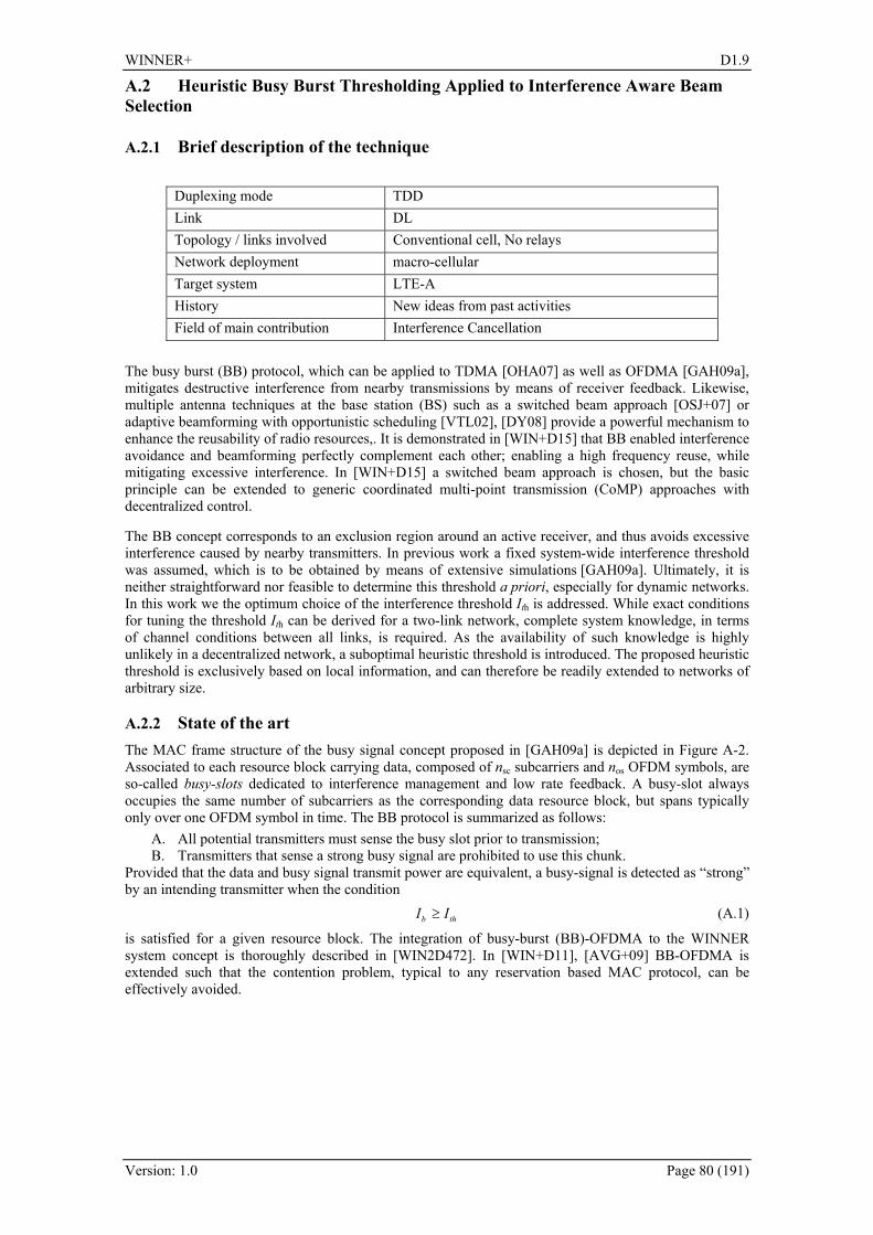
WINNER+ D1.9
Version: 1.0 Page 80 (191)
A.2 Heuristic Busy Burst Thresholding Applied to Interference Aware Beam Selection
A.2.1 Brief description of the technique
Duplexing mode TDD Link DL Topology / links involved Conventional cell, No relays Network deployment macro-cellular Target system LTE-A History New ideas from past activities Field of main contribution Interference Cancellation
The busy burst (BB) protocol, which can be applied to TDMA [OHA07] as well as OFDMA [GAH09a], mitigates destructive interference from nearby transmissions by means of receiver feedback. Likewise, multiple antenna techniques at the base station (BS) such as a switched beam approach [OSJ+07] or adaptive beamforming with opportunistic scheduling [VTL02], [DY08] provide a powerful mechanism to enhance the reusability of radio resources,. It is demonstrated in [WIN+D15] that BB enabled interference avoidance and beamforming perfectly complement each other; enabling a high frequency reuse, while mitigating excessive interference. In [WIN+D15] a switched beam approach is chosen, but the basic principle can be extended to generic coordinated multi-point transmission (CoMP) approaches with decentralized control.
The BB concept corresponds to an exclusion region around an active receiver, and thus avoids excessive interference caused by nearby transmitters. In previous work a fixed system-wide interference threshold was assumed, which is to be obtained by means of extensive simulations [GAH09a]. Ultimately, it is neither straightforward nor feasible to determine this threshold a priori, especially for dynamic networks. In this work we the optimum choice of the interference threshold Ith is addressed. While exact conditions for tuning the threshold Ith can be derived for a two-link network, complete system knowledge, in terms of channel conditions between all links, is required. As the availability of such knowledge is highly unlikely in a decentralized network, a suboptimal heuristic threshold is introduced. The proposed heuristic threshold is exclusively based on local information, and can therefore be readily extended to networks of arbitrary size.
A.2.2 State of the art The MAC frame structure of the busy signal concept proposed in [GAH09a] is depicted in 287HFigure A-2. Associated to each resource block carrying data, composed of nsc subcarriers and nos OFDM symbols, are so-called busy-slots dedicated to interference management and low rate feedback. A busy-slot always occupies the same number of subcarriers as the corresponding data resource block, but spans typically only over one OFDM symbol in time. The BB protocol is summarized as follows:
A. All potential transmitters must sense the busy slot prior to transmission; B. Transmitters that sense a strong busy signal are prohibited to use this chunk.
Provided that the data and busy signal transmit power are equivalent, a busy-signal is detected as “strong” by an intending transmitter when the condition b thI I≥ (A.1)
is satisfied for a given resource block. The integration of busy-burst (BB)-OFDMA to the WINNER system concept is thoroughly described in [WIN2D472]. In [WIN+D11], [AVG+09] BB-OFDMA is extended such that the contention problem, typical to any reservation based MAC protocol, can be effectively avoided.
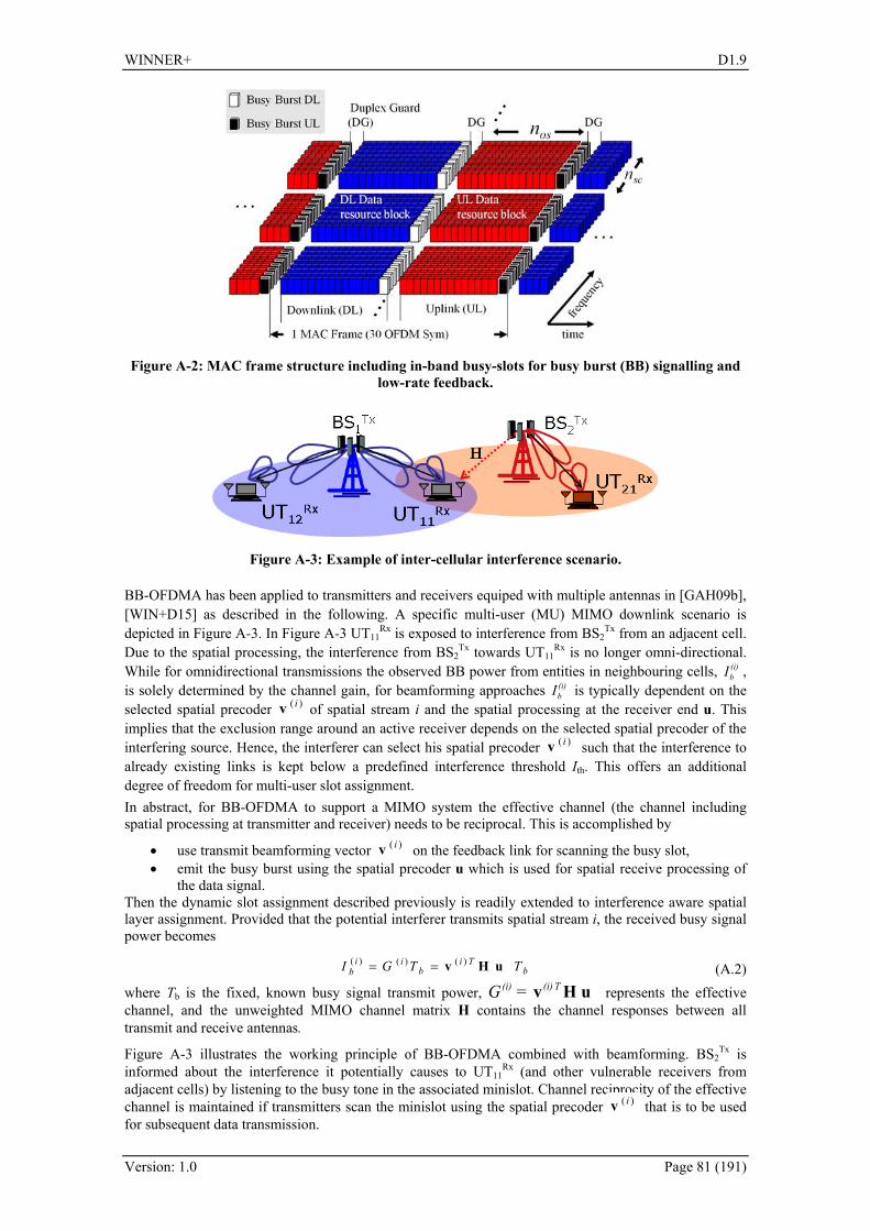
WINNER+ D1.9
Version: 1.0 Page 81 (191)
Figure A-2: MAC frame structure including in-band busy-slots for busy burst (BB) signalling and low-rate feedback.
Figure A-3: Example of inter-cellular interference scenario.
BB-OFDMA has been applied to transmitters and receivers equiped with multiple antennas in [GAH09b], [WIN+D15] as described in the following. A specific multi-user (MU) MIMO downlink scenario is depicted in 288HFigure A-3. In 289HFigure A-3 UT11
Rx is exposed to interference from BS2Tx from an adjacent cell.
Due to the spatial processing, the interference from BS2Tx towards UT11
Rx is no longer omni-directional. While for omnidirectional transmissions the observed BB power from entities in neighbouring cells, (i)
bI , is solely determined by the channel gain, for beamforming approaches (i)
bI is typically dependent on the selected spatial precoder )( iv of spatial stream i and the spatial processing at the receiver end u. This implies that the exclusion range around an active receiver depends on the selected spatial precoder of the interfering source. Hence, the interferer can select his spatial precoder )( iv such that the interference to already existing links is kept below a predefined interference threshold Ith. This offers an additional degree of freedom for multi-user slot assignment. In abstract, for BB-OFDMA to support a MIMO system the effective channel (the channel including spatial processing at transmitter and receiver) needs to be reciprocal. This is accomplished by
• use transmit beamforming vector )( iv on the feedback link for scanning the busy slot, • emit the busy burst using the spatial precoder u which is used for spatial receive processing of
the data signal. Then the dynamic slot assignment described previously is readily extended to interference aware spatial layer assignment. Provided that the potential interferer transmits spatial stream i, the received busy signal power becomes
bTi
bii
b TTGI uHv )()()( == (A.2) where Tb is the fixed, known busy signal transmit power, uHv T(i)(i) =G represents the effective channel, and the unweighted MIMO channel matrix H contains the channel responses between all transmit and receive antennas.
290HFigure A-3 illustrates the working principle of BB-OFDMA combined with beamforming. BS2Tx is
informed about the interference it potentially causes to UT11Rx (and other vulnerable receivers from
adjacent cells) by listening to the busy tone in the associated minislot. Channel reciprocity of the effective channel is maintained if transmitters scan the minislot using the spatial precoder )( iv that is to be used for subsequent data transmission.

WINNER+ D1.9
Version: 1.0 Page 82 (191)
A.2.3 Proposed innovation
Optimum Threshold for a 2 Link Network: In the following the problem of BB threshold selection with the objective of maximising the sum rate is reviewed. A 2 link network as depicted in 291HFigure A-4 where Tx1 communicates with Rx1 and Tx2 communicates with Rx2.Given that each receiver decodes only its intended signal and treats all other signals as noise, the sum rate can be written as 2 1 2 2log (1 ) log (1 )C γ γ= + + + (A.3)
where
111
21
G PG P N
γ =+
, 222
12
G PG P N
γ =+
denote signal to interference plus noise ratios (SINRs) at receivers Rx1 and Rx2. The maximum transmitter power is denoted by P. Moreover, Gxy denotes the path gain between transmitter Txx and receiver Rxy, x,y ∈1,2, and N accounts for the variance of zero-mean additive white Gaussian noise. The channel gain between nodes x and y, T
xy xyG = v H u , includes spatial processing at the transmitter and receiver.
G11
G21
G22
G12
Tx1 Rx1
Tx2
Rx2
BB
Figure A-4: Two-link wireless network. Solid and dashed arrows indicate intended communication links and interference.
Suppose that link 1 (Tx1 to Rx1) is already active and link 2 (Tx2 to Rx2) attempts to access a certain resource block. It is shown in [SBS+09] that the activation of link 2 increases the sum rate if the interference threshold is set to:
( )2th, opt 11 12 22 21
11 12
42
NI Z Z G G G GG G
= + + (A.4)
Unfortunately, this solution requires full knowledge of channel state information, which might not be available in practical systems. Furthermore, the extension to multiple links is cumbersome and is not pursued here. Special case of symmetric path gains: Consider the case where the intended links (Tx1 to Rx1) and (Tx2 to Rx2) experience the same path gain, G11=G22. Likewise, interfering links (Tx1 to Rx2) and (Tx2 to Rx1) also have the same path gain, G12=G21. Then the condition for the optimum threshold can be rewritten as
th, sym 11I NPG= (A.5)
Extension to multiple links: The optimum threshold for the special case of symmetric channel gains has the appealing property that it only depends on, G11, the channel gain of link 1. This means that extension to multiple links is straightforward, although the interference threshold (A.5) is, in general, suboptimal. In practice, some further aspects call for an adjustment of the variable interference threshold:
• Practical modulation and coding schemes do not achieve the Shannon capacity bound (A.3) which was used to derive the optimal threshold
• In a network with multiple links interference from remote links aggregates to an interference temperature that is substantially higher than thermal noise N.
• In a wireless network with multiple links more than 2 links may be active concurrently. This means that the potential gains of allowing multiple links to transmit concurrently are higher compared to a 2-link network.
All the above points imply that the threshold (A.5) is too optimistic, in the way that the exclusion range of an active receiver is too large. To compensate for this a scaling factor Δ>1 is introduced:
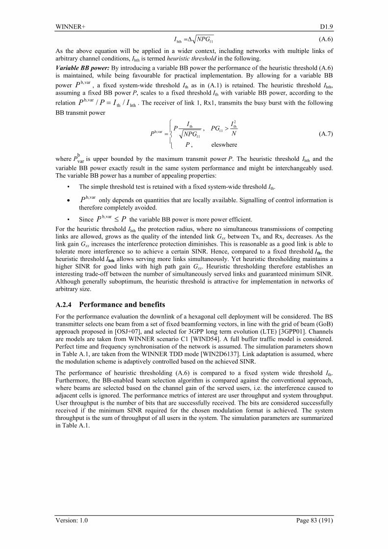
WINNER+ D1.9
Version: 1.0 Page 83 (191)
hth 11I NPG=Δ (A.6)
As the above equation will be applied in a wider context, including networks with multiple links of arbitrary channel conditions, Ihth is termed heuristic threshold in the following. Variable BB power: By introducing a variable BB power the performance of the heuristic threshold (A.6) is maintained, while being favourable for practical implementation. By allowing for a variable BB power varb,P , a fixed system-wide threshold Ith as in (A.1) is retained. The heuristic threshold Ihth, assuming a fixed BB power P, scales to a fixed threshold Ith with variable BB power, according to the relation hthth
varb, // IIPP = . The receiver of link 1, Rx1, transmits the busy burst with the following BB transmit power
2th th
11b,var11
,
, eleswhere
I IP PG
NP NPGP
⎧>⎪
= ⎨⎪⎩
(A.7)
where Pbvar is upper bounded by the maximum transmit power P. The heuristic threshold Ihth and the
variable BB power exactly result in the same system performance and might be interchangeably used. The variable BB power has a number of appealing properties:
• The simple threshold test is retained with a fixed system-wide threshold Ith.
• varb,P only depends on quantities that are locally available. Signalling of control information is therefore completely avoided.
• Since PP ≤varb, the variable BB power is more power efficient. For the heuristic threshold Ihth the protection radius, where no simultaneous transmissions of competing links are allowed, grows as the quality of the intended link Gxx between Txx and Rxx decreases. As the link gain Gxx increases the interference protection diminishes. This is reasonable as a good link is able to tolerate more interference so to achieve a certain SINR. Hence, compared to a fixed threshold Ith, the heuristic threshold Ihth allows serving more links simultaneously. Yet heuristic thresholding maintains a higher SINR for good links with high path gain Gxx. Heuristic thresholding therefore establishes an interesting trade-off between the number of simultaneously served links and guaranteed minimum SINR. Although generally suboptimum, the heuristic threshold is attractive for implementation in networks of arbitrary size.
A.2.4 Performance and benefits For the performance evaluation the downlink of a hexagonal cell deployment will be considered. The BS transmitter selects one beam from a set of fixed beamforming vectors, in line with the grid of beam (GoB) approach proposed in [OSJ+07], and selected for 3GPP long term evolution (LTE) [3GPP01]. Channels are models are taken from WINNER scenario C1 [WIND54]. A full buffer traffic model is considered. Perfect time and frequency synchronisation of the network is assumed. The simulation parameters shown in 292HTable A.1, are taken from the WINNER TDD mode [WIN2D6137]. Link adaptation is assumed, where the modulation scheme is adaptively controlled based on the achieved SINR.
The performance of heuristic thresholding (A.6) is compared to a fixed system wide threshold Ith. Furthermore, the BB-enabled beam selection algorithm is compared against the conventional approach, where beams are selected based on the channel gain of the served users, i.e. the interference caused to adjacent cells is ignored. The performance metrics of interest are user throughput and system throughput. User throughput is the number of bits that are successfully received. The bits are considered successfully received if the minimum SINR required for the chosen modulation format is achieved. The system throughput is the sum of throughput of all users in the system. The simulation parameters are summarized in 293HTable A.1.

WINNER+ D1.9
Version: 1.0 Page 84 (191)
Table A.1: Simulation Parameters.
Parameters Value OFDM symbol length (including CP) 22.48 μs
Carrier Frequency 3.95 GHz System bandwidth 89.84 MHz
Number of subcarriers 1840 Frame duration 0.6912 ms
OFDM symbols/frame 30 Resource block (RB) size (time x frequency) = 15 x 8 = 120
Number of sectors/cell 3 Number of antenna elements/sector 4
Average number of users/cell 10 Transmit power per RB 16.4 dBm Elevation antenna gain 14 dBi
Azimuth antenna element gain
⎪⎭
⎪⎬⎫
⎪⎩
⎪⎨⎧
⎟⎟⎠
⎞⎜⎜⎝
⎛− mA,12min
2
3dBθθ [dB],
where θ3dB=70o and Am=20 Noise level / RB -117.8 dBm
Number of snapshots 100 Simulation duration per snapshot 75 ms
294HFigure A-5 shows the system throughput (top) and user throughput (bottom) of BB-enabled beam selection with fixed and heuristic thresholding. Results for conventional beam selection are also included for comparison. It can be observed that BB-OFDMA with GoB outperforms the conventional GoB approach, both in terms of system throughput and user throughput. Heuristic thresholding, with the scaling factors Δ=18 dB in (A.6), is seen to attain a somewhat superior trae-off between system and user throughput. While a fixed threshold of Ith=-70dBm achieves the highest system throughput, the corresponding user throughput is significantly lower than for a fixed threshold of Ith=-75dBm. Heuristic thresholding, on the other hand, attains a high user throughput, while the system throughput is higher than that of a fixed threshold of Ith=-75dBm.
120 130 140 150 160 170 180 190 2000
0.10.20.30.40.50.60.70.80.9
1
Throughput [Mbps/cell]
cdf
System Throughput
-70 dBm-75 dBmFull reuseheuristic, Δ = 18 dB
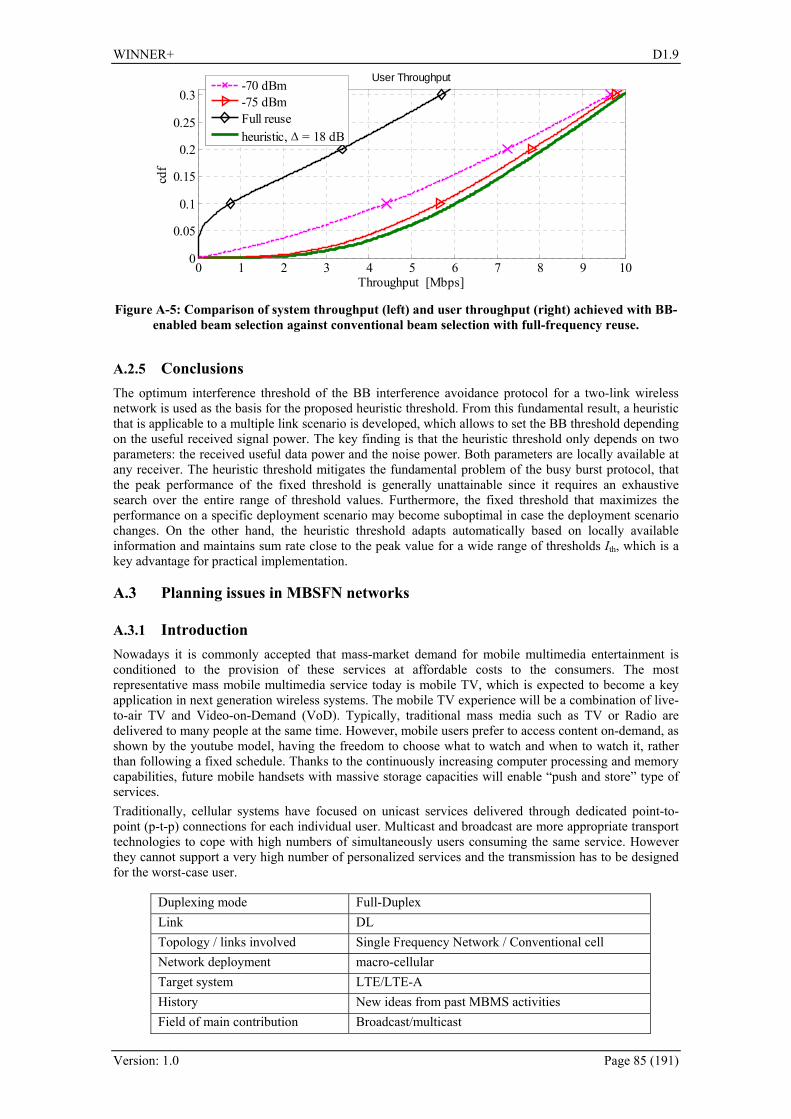
WINNER+ D1.9
Version: 1.0 Page 85 (191)
0 1 2 3 4 5 6 7 8 9 100
0.05
0.1
0.15
0.2
0.25
0.3
Throughput [Mbps]
cdf
User Throughput
-70 dBm-75 dBmFull reuseheuristic, Δ = 18 dB
Figure A-5: Comparison of system throughput (left) and user throughput (right) achieved with BB-enabled beam selection against conventional beam selection with full-frequency reuse.
A.2.5 Conclusions The optimum interference threshold of the BB interference avoidance protocol for a two-link wireless network is used as the basis for the proposed heuristic threshold. From this fundamental result, a heuristic that is applicable to a multiple link scenario is developed, which allows to set the BB threshold depending on the useful received signal power. The key finding is that the heuristic threshold only depends on two parameters: the received useful data power and the noise power. Both parameters are locally available at any receiver. The heuristic threshold mitigates the fundamental problem of the busy burst protocol, that the peak performance of the fixed threshold is generally unattainable since it requires an exhaustive search over the entire range of threshold values. Furthermore, the fixed threshold that maximizes the performance on a specific deployment scenario may become suboptimal in case the deployment scenario changes. On the other hand, the heuristic threshold adapts automatically based on locally available information and maintains sum rate close to the peak value for a wide range of thresholds Ith, which is a key advantage for practical implementation.
A.3 Planning issues in MBSFN networks
A.3.1 Introduction Nowadays it is commonly accepted that mass-market demand for mobile multimedia entertainment is conditioned to the provision of these services at affordable costs to the consumers. The most representative mass mobile multimedia service today is mobile TV, which is expected to become a key application in next generation wireless systems. The mobile TV experience will be a combination of live-to-air TV and Video-on-Demand (VoD). Typically, traditional mass media such as TV or Radio are delivered to many people at the same time. However, mobile users prefer to access content on-demand, as shown by the youtube model, having the freedom to choose what to watch and when to watch it, rather than following a fixed schedule. Thanks to the continuously increasing computer processing and memory capabilities, future mobile handsets with massive storage capacities will enable “push and store” type of services. Traditionally, cellular systems have focused on unicast services delivered through dedicated point-to-point (p-t-p) connections for each individual user. Multicast and broadcast are more appropriate transport technologies to cope with high numbers of simultaneously users consuming the same service. However they cannot support a very high number of personalized services and the transmission has to be designed for the worst-case user.
Duplexing mode Full-Duplex Link DL Topology / links involved Single Frequency Network / Conventional cell Network deployment macro-cellular Target system LTE/LTE-A History New ideas from past MBMS activities Field of main contribution Broadcast/multicast

WINNER+ D1.9
Version: 1.0 Page 86 (191)
A.3.2 Proposed technique In 3GPP, cell broadcast bearers have been standardized as part of MBMS, commercial availability since the beginning of 2008. LTE takes MBMS one step further to provide highly efficient multi-cell broadcast. By transmitting not only identical signals from multiple cell sites (with identical coding and modulation), but also synchronize the transmission timing between cells, the signal at the mobile terminal will appear exactly as a signal transmitted from a single cell site and subject to multi-path propagation. Due to the OFDM robustness to multi-path propagation, such multi-cell transmission also referred to as Multicast–Broadcast Single-Frequency Network (MBSFN) transmission, will then improve the received signal strength. In the current Release 9 of the standard, only two alternatives for MBMS inclusion are considered. The former allows time division multiplexing (TDM) of unicast transmission and multicast transmission whereas the latter consist in separating both transmission modes in different carriers, that is, applying frequency division multiplexing (FDM). Concerning TDM, each frame comprises 10 subframes. Within the Physical Broadcast Channel (PBCH) system informs about which specific subframes are allocated to multicast transmission. Only subframes #1, # 2, # 3, # 6, # 7 and #8 can be used with this aim. Besides, the system can choose among reserving 1 up to 6 subframes at most for such multicast transmission. This contribution intends to clarify which is the best option for MBSFN planning including, apart from TDM and FDM, a third hybrid version that allows changing the TDM to only unicast transmission for time to time. This third option is motivated by the need of multicast transmission for a recovery phase in which low coverage users could be served with better-suited transmission modes. Note that only file delivery service is considered in this case.
A.3.3 Performance results Case 1: TDM transmission We first consider the case in which 10MHz are jointly allocated to unicast and multicast transmission. As shown in Figure A-6, the higher the number of TTI allocated to multicast users, the lower the average quality perceived by unicast counterparts.
100 101 102
10-2
10-1
100
Number of users per cell
Ave
rage
dat
a ra
te p
er u
ser (
Mbp
s)
10 unicast subframes 8 unicast subframes / 2 multicast subframes6 unicast subframes / 4 multicast subframes4 unicast subframes / 6 multicast subframes
Figure A-6: Unicast users performance with multicast TDM.
On the contrary, multicast users increase their QoS with higher number of subframes. This additional QoS can be measured with the time required for file delivery. In this case, we have considered three sizes for that file: 2, 4 and 8 MBytes. Figure A-7 represents the time required for the download of the file increasing the number of TTI allocated to multicast users. In this case CQI 7 has been considered conservative enough to serve more than 95% of users in the cell.

WINNER+ D1.9
Version: 1.0 Page 87 (191)
1 2 3 4 5 60
10
20
30
40
50
60
70
80
Number of subframes allocated to multicast users
File
Del
iver
y Ti
me
(s)
File size 2 MBFile size 4 MBFile size 8 MB
Figure A-7: Multicast users’ performance with TDM.
From Figure A-6 and given a certain number of unicast users and a desired QoS for these users, it can be easily derived the maximum number of subframes to be allocated to multicast. In case of flexibility, Figure A-7 demonstrates that most benefit for multicast occur for 3 subframes, whereas for a higher number of subframes the benefit is not so high. Case 2: Hybrid TDM transmission and unicast In this case not all the frames are TDM multiplexing unicast and multicast users. On the contrary, some frames will be only used by unicast services (pure unicast and also repair services). Next figures depict the performance of unicast users considering different number of subframes allocated to multicast and different percentages of time with TDM mode.
100
101
102
10-2
10-1
100
Number of users per cell
Ave
rage
dat
a ra
te p
er u
ser (
Mbp
s)
Only unicastTDM 2 multicast subframesTDM 2 multicast subframes 25%TDM 2 multicast subframes 50%TDM 2 multicast subframes 75%All users in unicast
Figure A-8: Unicast users performance in case 2 with 2 subframes allocated to multicast.

WINNER+ D1.9
Version: 1.0 Page 88 (191)
100
101
102
10-2
10-1
100
Number of users per cell
Ave
rage
dat
a ra
te p
er u
ser (
Mbp
s)
Only unicastTDM 4 multicast subframesTDM 4 multicast subframes 25%TDM 4 multicast subframes 50%TDM 4 multicast subframes 75%All users in unicast
Figure A-9: Unicast users performance in case 2 with 4 subframes allocated to multicast.
100
101
102
10-2
10-1
100
Number of users per cell
Ave
rage
dat
a ra
te p
er u
ser (
Mbp
s)
Only unicastTDM 6 multicast subframesTDM 6 multicast subframes 25%TDM 6 multicast subframes 50%TDM 6 multicast subframes 75%All users in unicast
Figure A-10: Unicast users performance in case 2 with 6 subframes allocated to multicast.
From the obtained results it can be concluded that when increasing the number of subframes allocated to multicast transmission it is more recommended to split the frames between TDM and only-unicast. This conclusion is not surprising, since for the point of view of unicast users it is always preferred to share as minimum resources as possible with multicast users. From the point of view of multicast users, the optimum scheme depends on the number of users requiring multicast services. Next figure represents some of the feasible modes. Of course, increasing the number of subframes allocated to multicast will increase users satisfaction but at the expenses of unicast services.

WINNER+ D1.9
Version: 1.0 Page 89 (191)
100
101
102
0
10
20
30
40
50
60
70
80
90
100
Number of multicast users per cell
File
Del
iver
y Ti
me
(s)
TDM 2 multicast subframesTDM 2 multicast subframes 25%TDM 2 multicast subframes 50%TDM 4 multicast subframesTDM 6 multicast subframesAll users in unicast
Figure A-11: Multicast users performance in case 2 with different number of subframes allocated to multicast.
Case 3: FDM transmission In this last case the same number of unicast and multicast users is assumed. Therefore, from the 10MHz available, half will be dedicated to unicast, i.e. 5 MHz, and the same for multicast. This last case has been compared with case 1, in order to assess its performance. As shown in the next two figures, this is never a good option, and hence TDM is preferred for unicast and multicast users.
100
101
102
10-2
10-1
100
Number of users per cell
Ave
rage
dat
a ra
te p
er u
ser (
Mbp
s)
10 unicast subframes 8 unicast subframes / 2 multicast subframes 6 unicast subframes / 4 multicast subframes 4 unicast subframes / 6 multicast subframes FDM
Figure A-12: Unicast users performance with FDM.
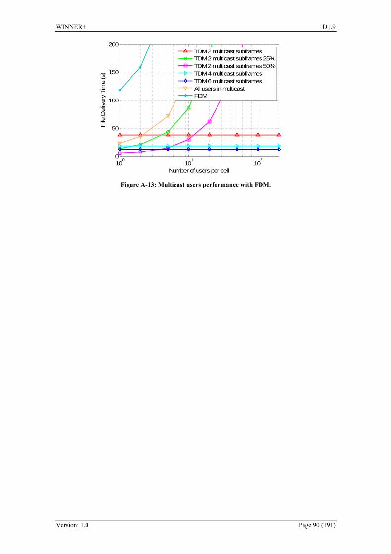
WINNER+ D1.9
Version: 1.0 Page 90 (191)
100
101
102
0
50
100
150
200
Number of users per cell
File
Del
iver
y Ti
me
(s)
TDM 2 multicast subframesTDM 2 multicast subframes 25%TDM 2 multicast subframes 50%TDM 4 multicast subframesTDM 6 multicast subframesAll users in multicastFDM
Figure A-13: Multicast users performance with FDM.
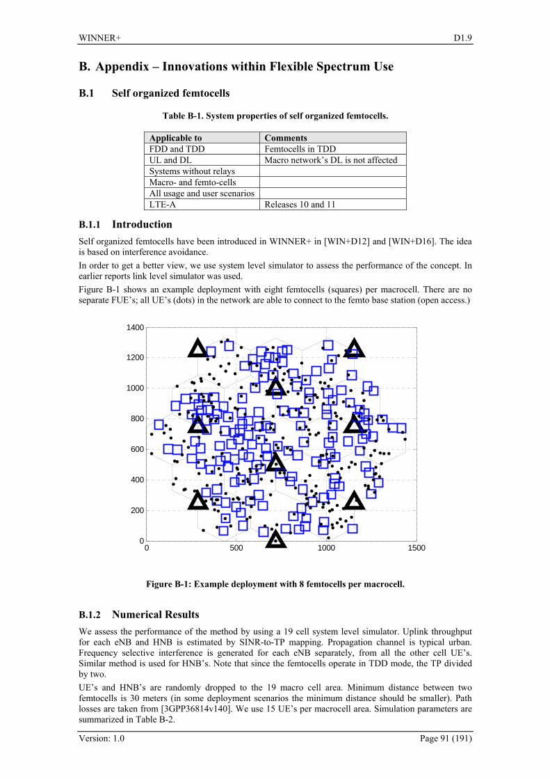
WINNER+ D1.9
Version: 1.0 Page 91 (191)
B. Appendix – Innovations within Flexible Spectrum Use
B.1 Self organized femtocells
Table B-1. System properties of self organized femtocells.
Applicable to Comments FDD and TDD Femtocells in TDD UL and DL Macro network’s DL is not affected Systems without relays Macro- and femto-cells All usage and user scenarios LTE-A Releases 10 and 11
B.1.1 Introduction Self organized femtocells have been introduced in WINNER+ in [WIN+D12] and [WIN+D16]. The idea is based on interference avoidance. In order to get a better view, we use system level simulator to assess the performance of the concept. In earlier reports link level simulator was used. 295HFigure B-1 shows an example deployment with eight femtocells (squares) per macrocell. There are no separate FUE’s; all UE’s (dots) in the network are able to connect to the femto base station (open access.)
0 500 1000 15000
200
400
600
800
1000
1200
1400
Figure B-1: Example deployment with 8 femtocells per macrocell.
B.1.2 Numerical Results We assess the performance of the method by using a 19 cell system level simulator. Uplink throughput for each eNB and HNB is estimated by SINR-to-TP mapping. Propagation channel is typical urban. Frequency selective interference is generated for each eNB separately, from all the other cell UE’s. Similar method is used for HNB’s. Note that since the femtocells operate in TDD mode, the TP divided by two. UE’s and HNB’s are randomly dropped to the 19 macro cell area. Minimum distance between two femtocells is 30 meters (in some deployment scenarios the minimum distance should be smaller). Path losses are taken from [3GPP36814v140]. We use 15 UE’s per macrocell area. Simulation parameters are summarized in 296HTable B-2.
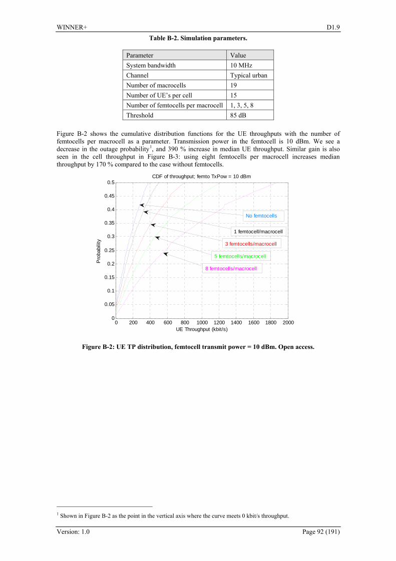
WINNER+ D1.9
Version: 1.0 Page 92 (191)
Table B-2. Simulation parameters.
Parameter Value System bandwidth 10 MHz Channel Typical urban Number of macrocells 19 Number of UE’s per cell 15 Number of femtocells per macrocell 1, 3, 5, 8 Threshold 85 dB
297HFigure B-2 shows the cumulative distribution functions for the UE throughputs with the number of femtocells per macrocell as a parameter. Transmission power in the femtocell is 10 dBm. We see a decrease in the outage probability 0F
1, and 390 % increase in median UE throughput. Similar gain is also seen in the cell throughput in 298HFigure B-3: using eight femtocells per macrocell increases median throughput by 170 % compared to the case without femtocells.
0 200 400 600 800 1000 1200 1400 1600 1800 20000
0.05
0.1
0.15
0.2
0.25
0.3
0.35
0.4
0.45
0.5CDF of throughput; femto TxPow = 10 dBm
UE Throughput (kbit/s)
Pro
babi
lity
No femtocells
1 femtocell/macrocell
3 femtocells/macrocell
5 femtocells/macrocell
8 femtocells/macrocell
Figure B-2: UE TP distribution, femtocell transmit power = 10 dBm. Open access.
1 Shown in Figure B-2 as the point in the vertical axis where the curve meets 0 kbit/s throughput.

WINNER+ D1.9
Version: 1.0 Page 93 (191)
0 1 2 3 4 5 6 7 8 9
x 104
0
0.1
0.2
0.3
0.4
0.5
0.6
0.7
0.8
0.9
1
Cell throughput (kbit/s)
Pro
babi
lity
No femtocells
1 femtocell/macrocell
3 femtocellsmacrocell
5 femtocells/macrocell
8 femtocells/macrocell
Figure B-3: Cell TP distribution, femtocell transmit power = 10 dBm. Open access.
299HFigure B-4 shows the performance with the HUE transmit power as a parameter (note that in the femtocell, the transmit power is the same for HUE and HNB.). As expected, increasing the Tx power also increases median TP. However, it is clearly seen that the difference between 15 dBm and 20 dBm is very small. This is further illustrated in 300HFigure B-5, which shows the median UE TP as a function of femtocell transmit power. After 20 dBm, the throughput starts to decrease due to increased interference.
0 200 400 600 800 1000 1200 1400 1600 1800 20000
0.05
0.1
0.15
0.2
0.25
0.3
0.35
0.4
0.45
0.5
UE throughput (kbit/s)
Pro
babi
lity
No femtocells
-5 dBm
0 dBm
10 dBm
5 dBm
15 dBm
-10 dBm
-15 dBm
20 dBm
Figure B-4: UE TP distribution with HUE transmit power as a parameter. Eight femtocells per macrocell area. Open access.

WINNER+ D1.9
Version: 1.0 Page 94 (191)
-10 -5 0 5 10 15 20 25 30 35 40 450
200
400
600
800
1000
1200
1400
1600
1800
2000
2200
Femtocell Tx power (dBm)
50 %
UE
thro
ughp
ut (k
bit/s
)
Figure B-5: Median UE throughput as a function of femtocell transmit power with eight femtocells per macrocell area. Open access.
However, in the results above, we assumed that all UE’s are able to connect to a femtocell, and that open access is used. Since these assumptions are not valid in many practical situations, we simulate the performance with closed access, and only a subset of the UE’s are able to use femtocells. Each femtocell has 3 dedicated UE’s in its closed subscription group (CSG), dropped in the vicinity of the femtocell (these UE’s can use macro network only if their femtocell is switched off). The remaining UE’s are dropped in the cell area randomly. These legacy UE’s do not have the capability to use femtocells. This causes increased macro-to-femto interference, as MUE’s close to femtocell interfere with the UL TDD transmission of the femtocell. 301HFigure B-6 shows the CSG and legacy UE median throughput as a function of femtocell transmit power. When the femtocell Tx power exceeds 5 dBm, the performance of legacy UEs starts to deteriorate due to increased femto-to-macro interference. The legacy UE throughput without femtocells is 405 kbit/s. When femtocells are used, the legacy UE TP is increased to 500 kbit/s. This is due to offloading effect: femtocells take part of the traffic leaving more resources for the macro cell users. The offloading gain in this example is 23.4 %. 302HFigure B-7 shows the outage probabilities for CSG UE’s and legacy UE’s. Again, due to interference, the outage probability starts to increase after femtocell transmit power exceeds a threshold, in this case 10 dBm. Also the CSG users’ outage increases after a certain threshold, presumably due to femto-to-femto interference. Outage limit was 10 kbit/s. Finally, 303HFigure B-8 shows the system TP for closed access.

WINNER+ D1.9
Version: 1.0 Page 95 (191)
-20 -10 0 10 20 30 400
500
1000
1500
2000
2500
3000
3500
4000
4500CSG users
Femtocell Tx power (dBm)
Med
ian
UE
TP
(kbi
t/s)
CSG usersLegacy users
Legacy UEs withoutfemtocells
Figure B-6: Median UE throughput for CSG and legacy UE’s. Closed access
´
-20 -10 0 10 20 30 400
5
10
15
20
25
30
35
40
45
50
Femtocell Tx power (dBm)
Out
age
prob
abili
ty (%
)
Legacy usersCSG users
Figure B-7: Outage probability. Closed access.

WINNER+ D1.9
Version: 1.0 Page 96 (191)
0 5 10 15 20 25 30 35 40 45 50 550
0.1
0.2
0.3
0.4
0.5
0.6
0.7
0.8
0.9
1
Cell throughput (Mbit/s)
Pro
babi
lity
CDF of cell TP
Without femtocells3 femtocells / macrocell
Figure B-8: Cell throughput. Closed access.
B.1.3 Conclusion We have reviewed the self organized femtocell contribution introduced in [WIN+D12] and [WIN+D16]. We have verified the concept by using system level simulator with 19 cells. Numerical results indicate significant gains. In the open access case, the system level gain is 170 % with eight femtocells per macro cell area. For closed access, macro UE performance is improved by 23 % due to offloading effect; system throughput is improved by 146 %.
B.2 Femtocell spectrum sharing from a game theoretical perspective
Table B-3. System properties of femtocells using game theory.
Applicable to Comments
FDD and TDD macrocell and femtocells in both TDD and FDD
UL and DL Macro network’s DL is not affected Systems without relays Macro- and femto-cells both are envisaged All usage and user scenarios LTE-A
B.2.1 Introduction We study the problem of spectrum sharing from a game theoretical perspective in which a eNB and several HNBs share the same spectrum band. This work is motivated by the huge interest in femtocell networks. Typically, in such a wireless network, several HNBs are installed by end users to provide signal coverage for a small area (home, enterprise, shopping mall). As a result, a number of interference scenarios can be envisaged. In this work, we focus on the downlink interference scenario at the macro UE who perceives interference from adjacent femtocell networks. The contribution of this work is two-fold: first in a pure non-cooperative case, we show that there is an optimal number of HNBs that can be deployed in a certain geographical area before the overall performance start decreasing. Second, through the concept of hierarchy, we show that better performance can be obtained hence bridging the gap between the selfish and fully centralized approach.

WINNER+ D1.9
Version: 1.0 Page 97 (191)
B.2.2 Non-cooperative (selfish) spectrum sharing scenario
Figure B-9: Deployment scenarios with one eNB and three HNBs with an emphasis on the downlink.
The above depicted access point deployment scenario can be cast into an interference channel in which every access point communicates with its intended UE. Since all access points share the same frequency band, interference is detrimental where all user terminals perceive interference from the other access points. Moreover, it is assumed that each sub-channel is preassigned to a different user by a scheduler. Hence, each user detects the signal only on the assigned sub-channel. As a result, a certain user i will receive a good signal from its serving AP as well as the other interfering APs.We consider a Gaussian interference channel with M (1 eNB + 1−M HNBs) APs simultaneously sending information to N user terminals on the same frequency band. Let H .be a random channel gain matrix whose ),( nm entry
is the channel power gain of the link from the thm AP to the thn UT. Moreover, we assume single user decoding at all receivers, meaning that signals from other APs are treated as interference.
The signal-to-interference plus noise ratio (SINR) of the signal from the thm AP to the thn UT is:
∑≠
+=
mjnjnj
nmnmnm ph
phSINR
,2
,2
,2
,, ||
||σ
(B.1)
where nmp , is the transmitter power by AP m towards UT n and 2σ represents the white Gaussian noise variance. The maximum achievable sum-rate for AP n is given by:
( )∑ +=n
nmm SINRR ,1log (B.2)
Moreover, every AP has a power constraint such that:
∑=
≤N
nmnm Pp
1
_
, (B.3)
Let us now formulate the first spectrum sharing game in which every access point behaves selfishly. In other words, every AP maximizes its achievable rate regardless of the interference it inflicts on other APs. This game falls within the umbrella of non-cooperative games where each player (AP) chooses its own power vector [ ]Nmm pp ,1, K subject to its total power constraint. The game is defined as follows:
• Players set: M,...,1
• Strategy set: ⎭⎬⎫
⎩⎨⎧
≤∀≥ ∑=
N
nmnmnmm Ppnpp
1
_
,, ,,0:
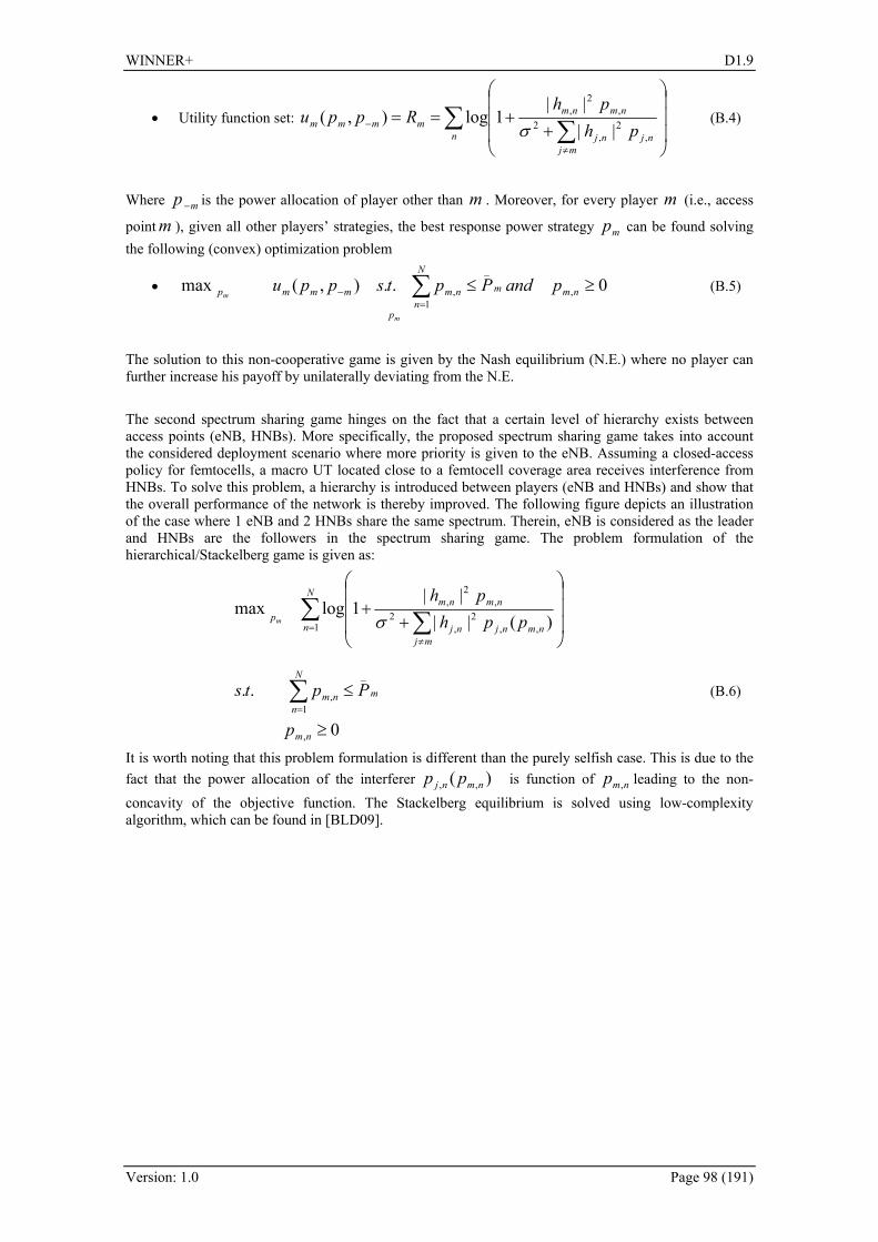
WINNER+ D1.9
Version: 1.0 Page 98 (191)
• Utility function set: ∑ ∑ ⎟⎟⎟
⎠
⎞
⎜⎜⎜
⎝
⎛
++==
≠
−n
mjnjnj
nmnmmmmm ph
phRppu
,2
,2
,2
,
||||
1log),(σ
(B.4)
Where mp − is the power allocation of player other than m . Moreover, for every player m (i.e., access
point m ), given all other players’ strategies, the best response power strategy mp can be found solving the following (convex) optimization problem
•
m
m
p
nm
N
nmnmmmmp pandPptsppu 0..),(max ,
1
_
, ≥≤∑=
− (B.5)
The solution to this non-cooperative game is given by the Nash equilibrium (N.E.) where no player can further increase his payoff by unilaterally deviating from the N.E.
The second spectrum sharing game hinges on the fact that a certain level of hierarchy exists between access points (eNB, HNBs). More specifically, the proposed spectrum sharing game takes into account the considered deployment scenario where more priority is given to the eNB. Assuming a closed-access policy for femtocells, a macro UT located close to a femtocell coverage area receives interference from HNBs. To solve this problem, a hierarchy is introduced between players (eNB and HNBs) and show that the overall performance of the network is thereby improved. The following figure depicts an illustration of the case where 1 eNB and 2 HNBs share the same spectrum. Therein, eNB is considered as the leader and HNBs are the followers in the spectrum sharing game. The problem formulation of the hierarchical/Stackelberg game is given as:
0
..
)(||||
1logmax
,
1
_
,
1 ,,2
,2
,2
,
≥
≤
⎟⎟⎟
⎠
⎞
⎜⎜⎜
⎝
⎛
++
∑
∑ ∑
=
=≠
nm
N
nmnm
N
nmj
nmnjnj
nmnmp
p
Ppts
pphph
m σ
(B.6)
It is worth noting that this problem formulation is different than the purely selfish case. This is due to the fact that the power allocation of the interferer )( ,, nmnj pp is function of nmp , leading to the non-concavity of the objective function. The Stackelberg equilibrium is solved using low-complexity algorithm, which can be found in [BLD09].
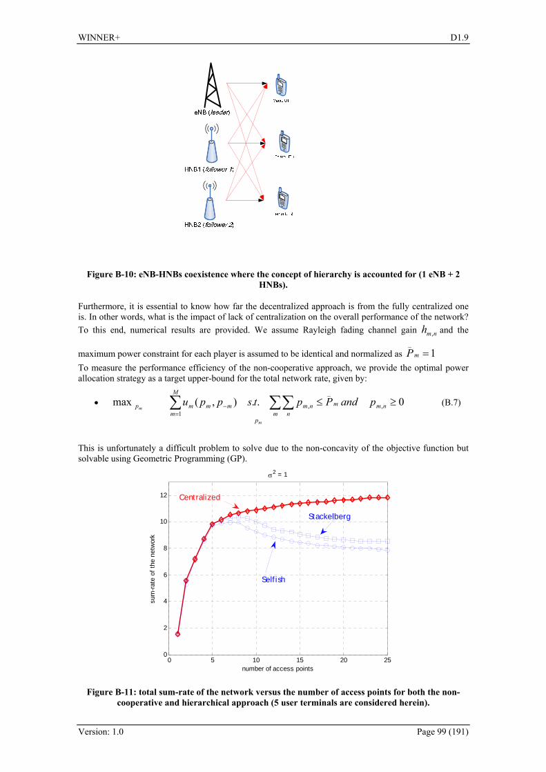
WINNER+ D1.9
Version: 1.0 Page 99 (191)
Figure B-10: eNB-HNBs coexistence where the concept of hierarchy is accounted for (1 eNB + 2 HNBs).
Furthermore, it is essential to know how far the decentralized approach is from the fully centralized one is. In other words, what is the impact of lack of centralization on the overall performance of the network? To this end, numerical results are provided. We assume Rayleigh fading channel gain nmh , and the
maximum power constraint for each player is assumed to be identical and normalized as 1_
=mP To measure the performance efficiency of the non-cooperative approach, we provide the optimal power allocation strategy as a target upper-bound for the total network rate, given by:
•
m
m
p
nmmm n
nm
M
mmmmp pandPptsppu 0..),(max ,
_
,1
≥≤∑∑∑=
− (B.7)
This is unfortunately a difficult problem to solve due to the non-concavity of the objective function but solvable using Geometric Programming (GP).
0 5 10 15 20 250
2
4
6
8
10
12
σ2 = 1
number of access points
sum
-rate
of t
he n
etw
ork
Stackelberg
Selfish
Centralized
Figure B-11: total sum-rate of the network versus the number of access points for both the non-cooperative and hierarchical approach (5 user terminals are considered herein).
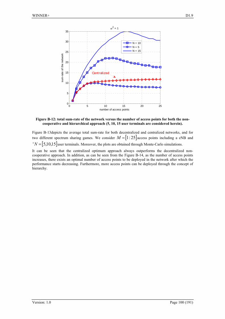
WINNER+ D1.9
Version: 1.0 Page 100 (191)
0 5 10 15 20 250
5
10
15
20
25
30
35σ2 = 1
number of access points
sum
-rate
of t
he n
etw
ork
N = 10N = 5N = 15
Centralized
Figure B-12: total sum-rate of the network versus the number of access points for both the non-cooperative and hierarchical approach (5, 10, 15 user terminals are considered herein).
Figure B-13depicts the average total sum-rate for both decentralized and centralized networks, and for two different spectrum sharing games. We consider [ ]25:1=M access points including a eNB and
[ ]15,10,5' =N user terminals. Moreover, the plots are obtained through Monte-Carlo simulations.
It can be seen that the centralized optimum approach always outperforms the decentralized non-cooperative approach. In addition, as can be seen from the Figure B-14, as the number of access points increases, there exists an optimal number of access points to be deployed in the network after which the performance starts decreasing. Furthermore, more access points can be deployed through the concept of hierarchy.

WINNER+ D1.9
Version: 1.0 Page 101 (191)
C. Appendix – Innovations within Relaying
C.1 Relay-capable flow management and QoS scheduling Applicability Comment Duplexing mode FDD/TDD FDD/TDD Link (UL/DL) UL/DL Usage and deployment and usage scenario (hot spot, micro-cellular, macro-cellular)
Any
Support for relays Yes Flow management has been introduced in former reports in order to allow for QoS scheduling in the MAC layer. In this section, the results for the technique are presented.
In order to be able to distinguish different flows and, hence, support QoS requirements by prioritising flows belonging to QoS classes with higher priorities, a mechanism to uniquely identify flows must be used. A flow can be understood as a DLL connection. We define it in the following way:
A flow is a logical group of packets which have a common attribute. This attribute may be the QoS class or the application the packets belong to.
Details can be found in [WIN+D15]. In this approach an IP Convergence Layer (IPCL) would read the TCP/IP- and UDP/IP-headers. Furthermore, a cross-layer interface for QoS aware requests by e.g. the application on top of the TCP/UDP/IP protocols would be necessary. One main point of this contribution is the solution to handle, i.e. establish and release the flows, especially in the case of supporting multiple hops. Packets belonging to the same flow are labelled with the same DLL flow ID. 304HFigure C-1 shows the protocol layers which are aware of flow IDs.
Figure C-1: Protocol layers with knowledge about DLL flow IDs.
Through the ability to identify the flow a packet belongs to, packets of higher layer applications can be identified and mapped to their QoS needs and handled accordingly, e.g. by different ARQ instances for different flows or prioritised resource scheduling. Adding a flow ID to the packets obviously increases the signalling overhead and of course it is desired to minimise the length of the flow ID field in the protocol header.
The validity of the flow ID is limited locally. The approach, which is preferred and is taken as a basis in the following, is to assign only locally, say hop-wise valid flow IDs, which are stored in tables and are map incoming flow IDs valid for the access links only to outgoing flow IDs valid for the backhaul link only. This approach would minimise the signalling overhead, but increase the hardware costs in terms of
RN UT
log. RLC conn. flow
L2 LLC connection
BS
Wire
Server
RF
L3 virtual connection
log. RLC conn. flow
IP IP
IPCL
LLC
BSSGP
Network Service
L2
L1bis L1
RLC BSSGP
MAC Network Service
PHY L1bis
RLC RLC
MAC MAC
PHY PHY
GW
RF
TCP/ UDP
IP
L2
L1
4
3
2
1
TCP/ UDP
IP
IPCL
LLC
RLC
MAC
PHY

WINNER+ D1.9
Version: 1.0 Page 102 (191)
required memory. However, these hardware costs can be neglected nowadays. This approach is illustrated in 305HFigure C-2.
Figure C-2: Hop-wise valid DLL flow IDs.
The flow establishment and signalling methods can be found in the previous report D1.5. The following figures explain the sequence of messages. More details can be found in the paper [OSW09].
Figure C-3: Flow establishment initiated by the UT (Message Sequence Chart).
Figure C-4: Flow establishment initiated by the BS (Message Sequence Chart).
After having introduced the flow management concept it is now possible to support QoS-aware resource scheduling, both in BSs and RNs. Those connections which have higher QoS needs in terms of, e.g. a
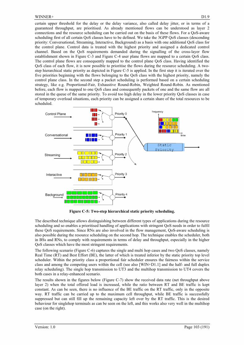
WINNER+ D1.9
Version: 1.0 Page 103 (191)
certain upper threshold for the delay or the delay variance, also called delay jitter, or in terms of a guaranteed throughput, are prioritised. As already mentioned flows can be understood as layer 2 connections and the resource scheduling can be carried out on the basis of these flows. For a QoS-aware scheduling first of all certain QoS classes have to be defined. We take the 3GPP QoS classes (descending priority: Conversational, Streaming, Interactive, Background) as a basis with one additional QoS class for the control plane. Control data is treated with the highest priority and assigned a dedicated control channel. Based on the QoS requirements demanded during the signalling of the cross-layer flow establishment shown in 306HFigure C-3 and 307HFigure C-4 user plane flows are mapped to a certain QoS class. The control plane flows are consequently mapped to the control plane QoS class. Having identified the QoS class of each flow, it is now possible to prioritise the flows during the resource scheduling. A two-step hierarchical static priority as depicted in 308HFigure C-5 is applied. In the first step it is iterated over the five priorities beginning with the flows belonging to the QoS class with the highest priority, namely the control plane class. In the second step a packet scheduling is performed based on a certain scheduling strategy, like e.g. Proportional-Fair, Exhaustive Round-Robin, Weighted Round-Robin. As mentioned before, each flow is mapped to one QoS class and consequently packets of one and the same flow are all stored in the queue of the same priority. To avoid too high delay in the lower priority QoS classes in case of temporary overload situations, each priority can be assigned a certain share of the total resources to be scheduled.
Figure C-5: Two-step hierarchical static priority scheduling.
The described technique allows distinguishing between different types of applications during the resource scheduling and so enables a prioritised handling of applications with stringent QoS needs in order to fulfil these QoS requirements. Since RNs are also involved in the flow management, QoS-aware scheduling is also possible during the resource scheduling on the second hop. The technique enables the scheduler, both in BSs and RNs, to comply with requirements in terms of delay and throughput, especially in the higher QoS classes which have the most stringent requirements. The following scenario (309HFigure C-6) captures the single and multi hop cases and two QoS classes, namely Real Time (RT) and Best Effort (BE), the latter of which is treated inferior by the static priority top level scheduler. Within the priority class a proportional fair scheduler ensures the fairness within the service class and among the competing users within the cell (see also [WIN+D1.1] and the half- and full duplex relay scheduling). The single hop transmission to UT3 and the multihop transmission to UT4 covers the both cases in a relay-enhanced scenario. The results shown in the figures below (310HFigure C-7) show the received data rate (net throughput above layer 2) when the total offered load is increased, while the ratio between RT and BE traffic is kept constant. As can be seen, there is no influence of the BE traffic on the RT traffic, only in the opposite way. RT traffic can be carried up to the maximum cell throughput, while BE traffic is successfully suppressed but can still fill up the remaining capacity left over by the RT traffic. This is the desired behaviour for singlehop terminals as can be seen on the left, and this works also very well in the multihop case (on the right).

WINNER+ D1.9
Version: 1.0 Page 104 (191)
Figure C-6: Multihop Multi-QoS Scenario.
Figure C-7: Throughput versus offered load for the Multihop Multi-QoS Scenario and a traffic mix of (BE:75%, RT:25%). Left: Singlehop. Right: Multihop (one relay).
C.2 Two-Way Relaying with MIMO AF relays Applicability Comment Duplexing mode FDD/TDD TDD Link (UL/DL) UL/DL Usage and deployment and usage scenario (hot spot, micro-cellular, macro-cellular)
Any
Support for relays Yes In [WIN+D17] Two-Way Relaying with MIMO AF relays was introduced as an efficient scheme for bidirectional exchange of information with the help of one relay. The system model is shown again here for convenience in 311HFigure C-8.

WINNER+ D1.9
Version: 1.0 Page 105 (191)
Figure C-8: Two-Way Relaying System model.
Two nodes that are equipped with M1 and M2 antennas, respectively, exchange data with the help of one AF relay having MR antennas not requiring any interaction from the base station. The two-way relaying scheme consists of two phases: In the first phase both nodes transmit to the relay where their transmissions interfere. Assuming frequency-flat fading, we can express the received signals at the relay as
R1 1 2 2 R C ,M= ⋅ + ⋅ + ∈r H x H x n (C.1)
where R 1 R 21 2C , CM M M M× ×∈ ∈H H represent the quasi-static block fading MIMO channel matrices
between the nodes and the relay, 1 21 2C , CM M∈ ∈x x are the transmitted vectors, and R
R CM∈n is the thermal noise at the relay. The AF relay amplifies the received signal by multiplying it with a complex amplification matrix R RCM M×∈G and transmits the amplified signal in the second transmission phase. The second transmission takes place in a subsequent time slot in a TDD fashion. We assume that reciprocity is valid. We can therefore express the received signal in the second time slot in the following manner
( )( )
1
2
T1 1 1 1 2 2 R 1
T2 2 1 1 2 2 R 2
C
C .
M
M
= ⋅ ⋅ ⋅ + ⋅ + + ∈
= ⋅ ⋅ ⋅ + ⋅ + + ∈
y H G H x H x n n
y H G H x H x n n (C.2)
Expanding these equations we find the following alternative representation
T T
1 1 1 1 1 2 2 1T T
2 2 2 2 2 1 1 2.
= ⋅ ⋅ ⋅ + ⋅ ⋅ ⋅ +
= ⋅ ⋅ ⋅ + ⋅ ⋅ ⋅ +
y H G H x H G H x n
y H G H x H G H x n
%
% (C.3)
We observe that the received signals for both nodes comprise three terms: The first term represents the self-interference the node receives from its own transmissions. The second term is the desired information from the other node. The third term represents the effective noise contribution which consists of the forwarded relay noise and the node’s own thermal noise contribution. We can conclude that the bidirectional two-way relaying transmission is feasible if both nodes have sufficient knowledge of the channel matrices 1 2,H H since the self-interference term can then be cancelled and the data transmissions can be decoded. Once the self-interference terms have been cancelled, the two-way relaying system is decoupled into two parallel single-user MIMO systems with effective channel matrices
(e) T
1,2 1 2
(e) T2,1 2 1
= ⋅ ⋅
= ⋅ ⋅
H H G H
H H G H (C.4)
Since they depend on the relay amplification matrix G , the system performance may be optimized by choosing G properly.
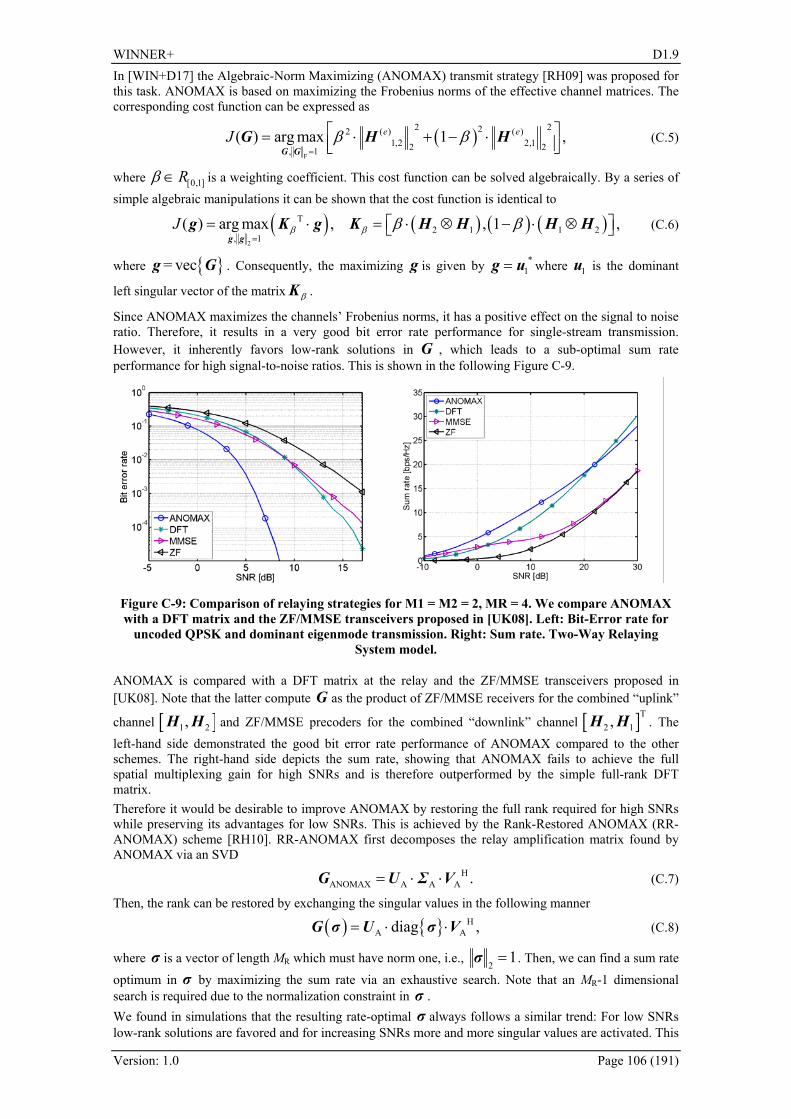
WINNER+ D1.9
Version: 1.0 Page 106 (191)
In [WIN+D17] the Algebraic-Norm Maximizing (ANOMAX) transmit strategy [RH09] was proposed for this task. ANOMAX is based on maximizing the Frobenius norms of the effective channel matrices. The corresponding cost function can be expressed as
( )F
2 222 ( ) ( )1,2 2,12 2, 1
( ) arg max 1 ,e eJ β β=
⎡ ⎤= ⋅ + − ⋅⎢ ⎥⎣ ⎦G GG H H (C.5)
where [0,1]Rβ ∈ is a weighting coefficient. This cost function can be solved algebraically. By a series of simple algebraic manipulations it can be shown that the cost function is identical to
( ) ( ) ( ) ( )2
T2 1 1 2
, 1( ) arg max , , 1 ,J β β β β
=⎡ ⎤= ⋅ = ⋅ ⊗ − ⋅ ⊗⎣ ⎦
g gg K g K H H H H (C.6)
where = vecg G . Consequently, the maximizing g is given by *1=g u where 1u is the dominant
left singular vector of the matrix βK .
Since ANOMAX maximizes the channels’ Frobenius norms, it has a positive effect on the signal to noise ratio. Therefore, it results in a very good bit error rate performance for single-stream transmission. However, it inherently favors low-rank solutions in G , which leads to a sub-optimal sum rate performance for high signal-to-noise ratios. This is shown in the following 312HFigure C-9.
Figure C-9: Comparison of relaying strategies for M1 = M2 = 2, MR = 4. We compare ANOMAX with a DFT matrix and the ZF/MMSE transceivers proposed in [UK08]. Left: Bit-Error rate for
uncoded QPSK and dominant eigenmode transmission. Right: Sum rate. Two-Way Relaying System model.
ANOMAX is compared with a DFT matrix at the relay and the ZF/MMSE transceivers proposed in [UK08]. Note that the latter compute G as the product of ZF/MMSE receivers for the combined “uplink”
channel [ ]1 2,H H and ZF/MMSE precoders for the combined “downlink” channel [ ]T2 1,H H . The
left-hand side demonstrated the good bit error rate performance of ANOMAX compared to the other schemes. The right-hand side depicts the sum rate, showing that ANOMAX fails to achieve the full spatial multiplexing gain for high SNRs and is therefore outperformed by the simple full-rank DFT matrix. Therefore it would be desirable to improve ANOMAX by restoring the full rank required for high SNRs while preserving its advantages for low SNRs. This is achieved by the Rank-Restored ANOMAX (RR-ANOMAX) scheme [RH10]. RR-ANOMAX first decomposes the relay amplification matrix found by ANOMAX via an SVD
ANOMAX A A A .Η= ⋅ ⋅G U Σ V (C.7)
Then, the rank can be restored by exchanging the singular values in the following manner
( ) A Adiag ,Η= ⋅ ⋅G σ U σ V (C.8)
where σ is a vector of length MR which must have norm one, i.e., 2
1=σ . Then, we can find a sum rate optimum in σ by maximizing the sum rate via an exhaustive search. Note that an MR-1 dimensional search is required due to the normalization constraint in σ . We found in simulations that the resulting rate-optimal σ always follows a similar trend: For low SNRs low-rank solutions are favored and for increasing SNRs more and more singular values are activated. This
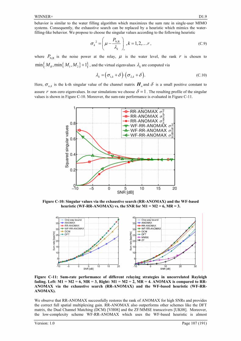
WINNER+ D1.9
Version: 1.0 Page 107 (191)
behavior is similar to the water filling algorithm which maximizes the sum rate in single-user MIMO systems. Consequently, the exhaustive search can be replaced by a heuristic which mimics the water-filling-like behavior. We propose to choose the singular values according to the following heuristic
N,R2 , 1, 2,kk
Pk rσ μ
λ+
⎛ ⎞= − =⎜ ⎟
⎝ ⎠K , (C.9)
where N,RP is the noise power at the relay, μ is the water level, the rank r is chosen to
1 2min ,min , 1RM M M + , and the virtual eigenvalues kλ are computed via
( ) ( )1, 2, .k k kλ σ δ σ δ= + ⋅ + (C.10)
Here, ,n kσ is the k-th singular value of the channel matrix nH and δ is a small positive constant to
assure r non-zero eigenvalues. In our simulations we choose 1δ = . The resulting profile of the singular values is shown in 313HFigure C-10. Moreover, the sum-rate performance is evaluated in 314HFigure C-11.
Figure C-10: Singular values via the exhaustive search (RR-ANOMAX) and the WF-based heuristic (WF-RR-ANOMAX) vs. the SNR for M1 = M2 = 6, MR = 3.
Figure C-11: Sum-rate performance of different relaying strategies in uncorrelated Rayleigh fading. Left: M1 = M2 = 6, MR = 3, Right: M1 = M2 = 2, MR = 4. ANOMAX is compared to RR-ANOMAX via the exhaustive search (RR-ANOMAX) and the WF-based heuristic (WF-RR-ANOMAX).
We observe that RR-ANOMAX successfully restores the rank of ANOMAX for high SNRs and provides the correct full spatial multiplexing gain. RR-ANOMAX also outperforms other schemes like the DFT matrix, the Dual Channel Matching (DCM) [VH08] and the ZF/MMSE transceivers [UK08]. Moreover, the low-complexity scheme WF-RR-ANOMAX which uses the WF-based heuristic is almost

WINNER+ D1.9
Version: 1.0 Page 108 (191)
indistinguishable from the RR-ANOMAX curve which requires an exhaustive search. Finally, RR-ANOMAX performs very close to the one-way upper bound which is obtained by choosing G to maximize the capacity of the two links in the two-way relaying system separately and then adding the resulting sum rates.
C.3 Split-Extend design for LDPC coded cooperation Applicability Comment Duplexing mode FDD/TDD FDD/TDD Link (UL/DL) DL Usage and deployment and usage scenario (hot spot, micro-cellular, macro-cellular)
Any
Support for relays Yes This work deals with a new code design for LDPC coding schemes distributed over a source and a relay. The cooperative transmission system implements the decode-and-forward protocol (315HFigure C-12), in which the relay first decodes the received signal, and then computes a new packet of parity bits which is forwarded to the destination.
S
R
DI,P1
I,P1
P2
Figure C-12: Distributed LDPC coding in a Source-Relay-Destination scheme.
Thus, such a distributed coding scheme is closely related to incremental redundancy, and some approaches have been already proposed in the literature, which are mainly based either on serial or parallel code concatenation. From the code design point of view, the serial or parallel concatenation of LDPC codes has intrinsic limitations, mainly because parity-check matrices used for decoding at the relay and the destination are included one in the other, resulting in inappropriate matrix topologies (density on non-zero entries, column and row weight distributions, cycles, etc.).
The proposed code design aims to create incremental redundancy for LDPC codes, while avoiding both serial and parallel concatenation. It is based on a “split-and-extend” approach, and allows the construction of codes with enhanced correction capacity and low integration cost. After decoding the received signal, the relay node computes extra parity bits by splitting parity-checks corresponding to rows of the parity-check matrix. Then the relay node transmits these new parity bits towards the destination. The whole process amounts to create a new matrix, whose rows correspond to parity-checks involving both old and new parity bits. This new matrix can be used at the destination to jointly decode the received signals from both the source and relay.
Simulation results over the Gaussian relay channel show an improvement of several dBs with the Split-Extend scheme compared to the case where the relay forwards the sequence of the information bits to the destination.
Split-Extend design The main idea The basic idea of the split-extend design can be resumed as follows. Let H1 be the parity-check matrix of the LDPC code used by the source for encoding the information sequence I. If the LDPC code is systematic, the encoded sequence is of the form (I, P1), where P1 is the sequence of parity bits, and we have that H1
.(I, P1)t = 0. Each row of H1 corresponds thereby to a parity-check equation involving source

WINNER+ D1.9
Version: 1.0 Page 109 (191)
and parity bits. The encoded sequence is transmitted from the source towards both the relay and the destination. After decoding the received signal, the relay computes extra parity bits by splitting parity-checks corresponding to rows of H1, as illustrated at 316HFigure C-13: the parity-check in the middle corresponds to a row of H1; in the left example, a new parity bit e1 is created by splitting the original parity-check into two parity-checks; in the right example, two new parity bits e1 and e2 are created by splitting the original parity-check into three parity-checks. The total number of extra parity bits depends on the number of rows of H1 (which is also equal to the length of P1) and the number of extra bits generated for each row of H1 (which may vary from one row to another). The sequence of all the extra parity bits, denoted by P2 = (e1, e2, …), is then transmitted from the relay to the destination. The matrix H obtained by the split-extension of H1 (i.e. the incidence matrix of the split-extended graph) verifies H.(I, P1, P2)t = 0, therefore it can be used at the destination in order to jointly decode the received signals from both the source and the relay.
Figure C-13: Example of split-extend design.
The general case In order to rigorously define the split-extend design, we first fix the notation:
• For any set E we denote by E the cardinality of E (number of elements of E )
• For any two sets E and F , FE \ denotes the set of elements E which are not in F .
• For any positive integer N , we denote by [ ]N:1 the set of integers between 1 et N : [ ] NN ,,2,1:1 K=
• If ( )NvvvV ,,, 21 K= is a vector of length N and [ ]NiiiE k :1,,, 21 ⊆= K , we denote by EV the length- k vector defined by the coordinates of V which are in E , that is:
( )kiiiE vvvV ,,,
21K=
Definition
Let 1H and H be two matrices of respective sizes 11 NM × and NM × , with NN ≤1 .
(a) We say that the rows kiii LLL ,,,
21K of H are obtained by “split-extending” the row jR of 1H ,
if there exists a subset [ ]NE :1⊆ of cardinality 1N (i.e. 1NE = ) such that:
[ ]0 and
\:12121=⊕⊕⊕=⊕⊕⊕
ENiiijEiii kkLLLRLLL KK
In this case, we also say that rows kiii LLL ,,,
21K are obtained by a “ k -split-extension” of the
row jR (note that for 1=k , a row iL is a 1-split-extension of jR if jEi RL = and
[ ] 0\:1 =ENiL )
(b) We say that the matrix H is obtained by “split-extending” the matrix 1H if there exist:
• a partition of the M rows of the matrix H in 1M disjoint subsets 11, , kL LK ,
1 21, ,k kL L+ K ,……, 11 11, ,M Mk kL L
− + K (so MkM =1
)
• and a subset [ ]NE :1⊆ with cardinality 1N (i.e. 1NE = )

WINNER+ D1.9
Version: 1.0 Page 110 (191)
such that for any 1,,1 Mm K= :
[ ] 0 and :12121 1111
=⊕⊕⊕=⊕⊕⊕ ++++ −−−− ENkkkmEkkk mmmmmmLLLRLLL KK ,
where 1
,,, 21 MRRR K denote the 1M rows of 1H (non necessarily in increasing order).
(note also that 11, , kL LK denotes any 1k distinct rows of H , which are not necessarily
consecutive; and the same holds for 1 21, ,k kL L+ K , etc.)
In this case, the sub-set E is called “set of columns corresponding to primary bits”, or by abusing language “set of primary bits” and [ ] EN \:1 is called “set of columns corresponding to complementary bits”, or by abusing language “set of complementary bits”.
Remark: The above definition is also valid for non-binary LDPC codes. In this case the parity-check matrices 1H and H are with coefficients in some Galois field )(qGF , and the ⊕ operator from the above definition stands for the addition in )(qGF .
Now, consider a matrix H that is obtained by split-extending a matrix 1H , and let E be the set of primary bits from the above definition.
(a) If ( )NxxX ,,1 K= is a codeword1F
2 of H , then EX is a codeword of 1H
(b) If 1X is a codeword of 1H and X is a codeword of H , such that 1XX E = , then X verifies the system:
⎪⎩
⎪⎨⎧
==⋅
1
0XX
XH
E
t
(C.11)
Matrices ( 1H , H ) can be used in a cooperative transmission system as follows:
• The source S encodes the packet of information bits I , generating a codeword 1X of 1H . It
sends 1X towards the relay R and the destination D. (note that if matrix 1H is systematic, then ( )11 , PIX = , where 1P is the packet of parity bits – but this condition is not necessary).
• The relay R decodes the received signal, correcting the transmission errors on 1X . Then it generates a codeword X of H , such that 1XX E = (for instance, by using the system (1)), and
sends the set of complementary bits (that is, [ ] ENX \:1 ) towards the destination D.
• Thus, D receives noisy versions of [ ]( ) [ ]( ) XXXXX ENEEN == \:1\:11 ,, (from both the source
and the relay), which can be decoded using the matrix H.
Note also that the proposed design can be used for transmission systems employing HARQ schemes with incremental redundancy: in this case, the set of complementary bits [ ] ENX \:1 is transmitted by the source
whenever the destination fails to decode 1X because of bad channel conditions.
Split-extend design for WiMAX-LDPC codes. In order to demonstrate the benefits of the proposed design, we applied it to the Quasi-Cyclic LDPC codes specified by the IEEE.802.16e (WiMAX) standard. Parity-check matrices of WiMAX-LDPC codes with coding rates 1/2 and 2/3 have been split-extended, such that the number of generated complementary parity bits be equal to the number of information bits. Thus, for coding rate 1/2, each row of the parity- 2 By abusing language, a codeword of the LDPC code with parity-check matrix H , will be simply called codeword of H . Thus, a “codeword” of H is a vector ( )NxxX ,,1 K= of length N such that
0=⋅ tXH , where tX denotes the transposed vector of X .

WINNER+ D1.9
Version: 1.0 Page 111 (191)
check matrix has been split into two rows; while for rate 2/3, each row of the parity-check matrix has been split into three rows. Splitting has been performed by a dedicated algorithm that searches for short cycles in the parity check matrix, then splits rows such as to break as many short cycles as possible. Parity-check matrices and their split-extended versions are shown in 317HFigure C-14 and 318HFigure C-15. Frame Error Rate performance of the Split-Extend design has been evaluated by Monte-Carlo simulation over the Gaussian relay channel, and has been compared with the performance obtained by forwarding the information sequence I from the relay to the destination. Simulation results presented at 319HFigure C-16 and 320HFigure C-17 satisfy the following rules:
• All the three links are AWGN channels with QPSK modulation.
• The source S uses either the WiMAX-LDPC code with rate 1/2 or 2/3:
o Solid curves (split-extend design): after decoding the received signal, the relay R generates and sends toward the destination a number of complementary parity bits equal to the number of information bits.
o Dashed curves: after decoding the received signal, the relay R forwards the sequence of information bits to the destination.
• SNR between Source and Relay is fixed such that the Frame Error Rate at the Relay is very low (about 10-5): 2.5 dB when the source uses the WiMAX-LDPC code with rate 1/2, and to 4.5 dB when the source uses the WiMAX-LDPC code with rate 2/3.
• To evaluate the SNR gain, the x-axis corresponds either to the SNR between Relay and Destination (left figures), or to the SNR between Source and Destination (right figures).
• Each curve color corresponds to some SNR on the remaining link (that is, Source to Destination for left figures, and Relay to Destination for right figures), which is given in the legend of each figure.
Finally 321HFigure C-18 follows the same rules, except that 16-QAM modulation is used on the Relay-to-Destination link.
We remark that in all cases the gain of the proposed design is in order of several dB (up to 4dB), depending on the quality of the Source-to-Destination or Relay-to-Destination links. Conclusion In conclusion, the proposed code design aims to create incremental redundancy for LDPC codes, while avoiding both serial and parallel concatenation. It is based on a “split-and-extend” approach, and allows the construction of codes with enhanced correction capacity and low integration cost. Besides advantageous applications for cooperative transmission systems, it can also be used for communication systems employing HARQ schemes with incremental redundancy. Finally, the proposed design can also be applied to existing codes, which allows for addressing cooperation issues for evolving standards, with a reduced impact on user equipment and maintaining backward compatibility.
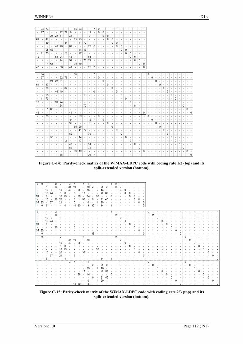
WINNER+ D1.9
Version: 1.0 Page 112 (191)
Figure C-14: Parity-check matrix of the WiMAX-LDPC code with coding rate 1/2 (top) and its split-extended version (bottom).
Figure C-15: Parity-check matrix of the WiMAX-LDPC code with coding rate 2/3 (top) and its split-extended version (bottom).

WINNER+ D1.9
Version: 1.0 Page 113 (191)
Figure C-16: Performance of the proposed SE design for rate 1/2 . Solid curves: Split-Extend design, Dashed curves: Relay Repetition scheme.
Figure C-17: Performance of the proposed SE design for rate 2/3. Solid curves: Split-Extend design, Dashed curves: Relay Repetition scheme.
Figure C-18: Performance of the proposed SE design for rate 2/3, with 16-QAM modulation on the Relay-Destination link. Solid curves: Split-Extend design, Dashed curves: Relay Repetition scheme.

WINNER+ D1.9
Version: 1.0 Page 114 (191)
C.4 Relaying in the framework of CoMP Applicability Comment Duplexing mode FDD/TDD TDD Link (UL/DL) UL and DL Usage and deployment and usage scenario (hot spot, micro-cellular, macro-cellular)
Any
Support for relays Yes
Non-relaying protocols suffer from a non-uniform spatial power distribution. The provision of a uniform spatial power distribution is the requirement for an energy-efficient delivery of high data rates. CoMP approaches already improve this distribution by canceling or avoiding interference, which otherwise worsens the SINR particularly at the cell edge. Alternatively, relaying can improve the spatial resource reuse by deploying additional RAPs, which aggregate user data and forward it to the BS (uplink) or to the UTs (downlink). In comparison to a conventional deployment with only BSs, relay-enhanced cells (REC) are a more flexible way to provide indoor coverage as well as coverage in otherwise shadowed areas, e.g., in street-canyons or densely developed downtown areas. However, usually the bottleneck in a REC is the link between BS and RN, which can be significantly improved using CoMP approaches. In [WIN+D18] we investigated the effect of interference on the performance of a relaying-based system using the interference-relay-channel where two BSs communicate with two UTs using the support of two RNs (each assigned to one communication pair) [RFL09],[Ros09]. Using this particular channel, we investigated different protocols, which either avoid interference (TDD), coordinate interference (Han-Kobayahi’s superposition coding [HK81]), or cancel interference (Dirty-Paper-Coding). One approach, which integrates CoMP and relaying, provides the highest performance gains. More specifically, this approach improves the link between BS and RN by using CoMP and it improves the spatial reuse and therefore the system throughput by using relay nodes with interference coordination (Han-Kobayashi coding). Based on these results we applied a conventional transmission approach, a CoMP approach using ZF-DPC [CS03], and relaying to the WINNER system level model [WIN2D6112]. Using this analysis we have been able to show and emphasize the ability of relaying to improve the worst-user performance in both wide-area and Manhattan-area scenario. Particularly in the Manhattan-area, indoors deployed RNs significantly improve the worst-user performance by about 2 orders. In addition, we provided numerical results for the spatial throughput distribution in a relay-enhanced system, which is more homogeneous than in a system using conventional or CoMP approaches. Furthermore, we provided results for different interference coordination approaches where a simple approach with either only common or only private messages provides the best performance while the computational complexity is reduced.
Figure C-19: Throughput CDF for downlink transmission in wide-area.

WINNER+ D1.9
Version: 1.0 Page 115 (191)
Figure C-20: Throughput CDF for uplink transmission in wide-area.
Figure C-21: Throughput CDF for uplink transmission in Manhattan-area.
In this deliverable, we provide new numerical results for uplink transmission in both Manhattan-area and wide-area. 322HFigure C-19 and 323HFigure C-20 show respectively the downlink and uplink throughput CDF for the wide-area reference scenario and using the parameters as in [WIN+D18]. Both figures demonstrate that the reduced average distance between a UT and its assigned RAP results in a significantly improved worst-user performance as well as average performance. This effect is even more dominant for the uplink performance in Manhattan-area as shown in 324HFigure C-21. Since most UTs are located indoors, the indoor deployment of additional relay nodes and CoMP on the BS-RN-link are capable to significantly improve the worst-user throughput performance by about three orders. Interestingly, the performance of using only relays to serve UTs and using the integrated approach do not differ significantly, which implies that most UTs have a very strong link towards a RN. In addition, this implies that multi-cell MIMO in a micro-cellular environment does not offer significant gains as the performance of individual UTs is not interference-limited but limited due to the strong shadowing caused by the building walls. Hence, in a micro-cellular scenario, BSs could be deployed on roof-top to serve only RNs while indoor RNs and RNs on street-level serve UTs.

WINNER+ D1.9
Version: 1.0 Page 116 (191)
Figure C-22: Cost-benefit tradeoff for uplink transmission in wide-area.
The previous results compared two different deployments: one without relay nodes and one, which was extended by additional relays. Although the REC setup provides a significant performance gain, we did not include the additional deployment costs in such a system. Hence, we provide in this deliverable a cost-benefit-tradeoff analysis where the costs of both deployments are normalized by extending the inter-site distance in the REC setup. More specifically, let the relative costs of a RN compared to a BS be αRN, then the inter-site distance in a REC is given by:
,( ) 1is RN is ref RN RNd d Nα α= +
where dis,ref is the inter-site distance in a conventional deployment (1000m) and NRN is the number of relays per site (6 in our setup). 325HTable C-1 shows an example for CAPEX and OPEX for a RN and site which results in the relative costs , 0.1RN refα = .
Table C-1: Example for initial and operating costs for a relay node and a site with three BSs. Item of Expenditure Relay Node Site with 3 BS Hardware 10 kEUR 80 kEUR Loan 3 years at 8% 8 years at 8% Installation 5 kEUR 30 kEUR Rental costs 100 EUR p.m. 1000 EUR p.m. Energy costs (at 10 Cent per kWh)
438 EUR p.a. (500 W) 4.4 kEUR p.a. (5kW)
Life-Span 10a 10a Cost-Ratio αRN,ref = 0.1 326HFigure C-22 shows the 5% quantile throughput performance for different relative relay cost values. The usage of an integrated approach provides a significant performance gain for all relative costs. This approach serves the cell-center and cell-edge between two cells at the same site using CoMP and the remaining, major part of the cell with RNs. These results imply that for the same deployment costs, relaying provides higher performance gains and still offers a more flexible deployment. Another aspect is the energy-efficiency of the network. In our setup a RN is transmitting with about 13% of the BS power. If αRN reflects the relative energy consumption of a RN compared to a BS, 327HFigure C-22 could be interpreted as an energy-normalizing plot. Assuming a similar ratio of 13%, the RECs setup provides significant performance gains even if the total energy consumption and deployment costs are normalized. Hence, relays not only provide performance gains at lower deployment costs but also at reduced energy consumption [RF10].
WINNER+ D1.9
Version: 1.0 Page 117 (191)
Within WINNER+ we introduced an approach to integrate the REC concept and CoMP in order to exploit the benefits of both approaches. In particular, we showed how a REC using CoMP on the link between BS and RN is able to improve the throughput by multiple orders. In addition, relaying promises to reduce the computational complexity, the energy consumption, and the deployment costs. Hence, relays are an ecological and economic option for systems based on direct transmission. In addition, RECs are more flexible and allow for a reuse of existing 2G and 3G sites in order to reduce the deployment costs.
C.5 Scheduling for heterogeneous traffic in OFDMA-based wireless relay enhanced cellular networks
Applicability Comment Duplexing mode FDD/TDD FDD/TDD Link (UL/DL) DL Usage and deployment and usage scenario (hot spot, micro-cellular, macro-cellular)
Any
Support for relays Yes Introduction HYGIENE (HurrY-Guided-Irrelevant-Eminent-NEeds ), a scheduling algorithm for heterogeneous traffic scenarios, has been presented in [WIN+D15]. This scheduling is based on the three following steps. First a Rushing Entity Classifier (REC) identifies rushing entities that must be treated with higher priority. Depending on the nature of the traffic, entities are UEs (NRT traffic) or packets (RT). Therefore, rushing entity classification is traffic-dependent. In a second step, the proposed scheduler deals with urgencies. Rushing entities are scheduled regardless of their momentary link quality. If any resources (here chunks) are still unscheduled, then in a third step, HYGIENE allocates resources to those users with better momentary link quality, regardless of their time constraints. The objective here is to present the adaptation of the HYGIENE scheduling to the context of relay enhanced cellular networks, and to compare its performance in terms of throughput, coverage and fairness between users with state of the art algorithms, in presence of mixed traffic for LTE-Advanced systems. Scheduling algorithm description The basic idea is to bring urgency on top of relaying, which means giving the priority to urgent users and then to relayed users. Obviously, some of the urgent users may belong to the set of users that require relaying. For sake of clarity, HYGIENE is first introduced in this section before explaining its adaptation to relay-enhanced cellular networks. HYGIENE scheduler, as already introduced in [WIN+D15], is described in 328HFigure C-23 and can be summarized as follows:
o First a Rushing Entity Classifier (REC) identifies rushing entities that must be treated with higher priority. Depending on the nature of the traffic, entities are UEs (NRT traffic) or packets (RT). Therefore, rushing entity classification is traffic-dependent. The REC classifies entities (packets or UEs) waiting to be scheduled as rushing or non-rushing. With RT traffic, packets are classified as rushing if rush TTLTh TTL Rη⋅ + ≥ , where Thrush is a threshold on the QoS deadline which depends on the traffic type, η is a constant which takes into account both retransmission interval and maximum allowed number of retransmissions. RTTL is the remaining Time To Live (TTL) of the packet. With NRT traffic, UEs and not packets are classified by the REC. Therefore, the ith UE (UEi) is classified as rushing if it has been under-served during the observation time window TWi. More precisely, every TTI the REC checks for each UEi if
min
,, R
txQoStTW idatai
inowi−
≤− , where tnow,i is the elapsed time since the beginning of TWi, QoSi
the QoS requirements of the UE class of traffic, txdata,i the total data transmitted by user i during (TWi-tnow,i) and Rmin the minimum transmission rate of the system. Note that Thrush, η and TWi are scheduler design parameters.
o In a second step, the proposed scheduler deals with urgencies. Rushing entities are scheduled regardless of their momentary link quality. Resources (chunks) are allocated to rushing entities with an EDF (Earliest Deadline First)-like scheduler which allocates best chunk(s) to entities

WINNER+ D1.9
Version: 1.0 Page 118 (191)
with higher deadline priority. Deadline priority metrics differ between RT and NRT traffics: with RT traffic deadline priority depends on RTTL, while with NRT traffic it depends on the lack of data transmitted during TWi. Again, chunks are selected in order to maximize the spectral efficiency.
o If any resources (here chunks) are still unscheduled, then in a third step they are allocated to users which maximize the cell throughput regardless of any QoS constraints of active UEs. Thus, the allocation is done according to MCI (Maximum Carrier to Interference ratio) per chunk
Figure C-23: HYGIENE steps.
The proposed adaptation to relay-enhanced cellular networks can then be described as follows. First a Rushing Entity classifies users into two sets, U(k) and U’(k) (resp. the set of urgent and non urgent users) based on the first step of the classical HYGIENE. Secondly the base station identifies the users that require relaying, where R(k) and R’(k) are respectively the set of relayed and not relayed users. This latter step is based on traditional SINR measurements, comparing the direct link with the two-hop link. Then resource allocation is performed, starting with the second TTI of a group of two consecutive TTIs (TTI+1) described in 329HFigure C-24, for urgent users that need cooperation (i.e. for U(k)∈R(k)) according to step2 of the HYGIENE scheduler. For RT Packets, each packet is prioritized according to its remaining TTL (RTTL) and then chunks are allocated to the ordered packets in order to maximize spectral efficiency. For non real time users, PF scheduling rule is applied.
Figure C-24: TTI+1 allocation step RS-UT (Relay Station to User Terminal = Relayed User), BS-UT (Base Station to User Terminal = Not relayed User).
Then for this same set of users (i.e. U(k)∈R(k)), resources are allocated in the first TTI (Base station to Relay phase, also called TTI phase, 330HFigure C-25): chunks are assigned according to a MCI policy, while matching the number of relayed users of the second TTI.

WINNER+ D1.9
Version: 1.0 Page 119 (191)
Figure C-25: TTI allocation step Bs-Rs (Base Station to Relay Station = first part of relayed user).
To match the relayed users a pairing policy is applied: same Modulation and Coding Scheme and same number of chunks for relayed user between second TTI and first TTI have to be guaranteed (331HFigure C-26). This is because for the moment, we consider an AF (Amplify and Forward) type of relay.
Figure C-26: Pairing Step.
Then, we allocate resources for urgent users that do not need cooperation (i.e. for U(k) ∈ R’(k)), starting with first TTI (and second TTI if rushing users are remaining). The allocation policy is the same than the one described at the beginning of this paragraph (classical HYGIENE). In the next step, resources are allocated to non urgent users, starting first with second TTI and then moving to the first TTI. In the second TTI, chunks of all non urgent users are assigned with a Max C/I policy. Then in the first TTI, for those users belonging to R(k), chunks are assigned according to a Max C/I policy, while matching the number of relayed users of second TTI. Last but not least, resources are allocated to users belonging to R’(k). The proposed allocations policies dealing with different traffic sources (real time and non real time) and urgencies are summarized in the 332HTable C-2.
Table C-2: Scheduler selection.
WINNER+ D1.9
Version: 1.0 Page 120 (191)
The priority rules of urgency over relaying can be summarized as shown in 333HTable C-3, where UR is the set of urgent relayed user, UNR is the set of urgent but not relayed users, U’R is the set of non urgent but relayed user sand U’NR is the set of non urgent and not relayed users. Equal priority is given to U’R and U’NR, as in state of the art (SoTA) algorithms.
Table C-3: Priority rules of urgency over relaying.
Type of user Scheduling Priority
UR 3 (Max)
UNR 2
U’R and U’NR 1 (SoTA)
Results In [WIN+D15], we gave performance results obtained with the HYGIENE scheduler without relaying. Here we provide some new results considering relay-enhanced cellular networks with the new 2TTIs allocation (HYGIENE²). We have measured Hygiene² performance in the following scenario:
o high load scenario without HARQ (600 users per sector) varying the rushing threshold Thrush
The details on the adopted system model are summarized in 334HTable C-4.
Table C-4: Main system model parameters. Network
Carrier Frequency 2GHz Bandwidth 10MHz
Inter-site distance 500m Minimum distance 35m
TTI duration 1ms Cell layout Hexagonal grid, 19 3-sectorized cells Relay node One relay per sector,
Amplify & Forward Link BS-RN is perfect.
Link to System Interface EESM Traffic Models VoIP
Nb of antennas (Tx, Rx) (1,1) Access Technique OFDMA
Total number of subcarriers 600 Nb of sub-carriers per chunk 12
Total number of chunks (PRB) 50 Propagation channel
Fast fading Typical Urban, 6-tap model, 3km/h Interference White
UE Channel estimation Ideal
CQI reporting Ideal Turbo-decoder Max Log-MAP (8 iterations)
Dynamic Resource Allocation Nb of MCS 12 (from QPSK 1/3 to 64 QAM ¾)
AMC PER target 10% CQI report Each TTI, with 2ms delay
Packet scheduling MCI Sub-carriers allocation strategy Chunk based allocation
WINNER+ D1.9
Version: 1.0 Page 121 (191)
Number of control channels per TTI 50 HARQ
Stop and Wait Synchronous adaptive Retransmission Interval 4ms
Maximum number of retransmissions Up to 3 (not active at the moment) Combining technique Chase
RUSHING THRESHOLD 0.3 – 0.5 -0.9
The idea is to compare the HYGIENE scheduler on the new 2-TTI structure without the relaying notion and finally the 2-TTI structure including different percentages of relayed users (varying a threshold). The new 2-TTI structure without relaying is obtained by considering the classical HYGIENE algorithm that schedules resources first on next TTI (TTI+1) and secondly on first TTI, as can be found in most related SoTA papers dealing with relay-enhanced cellular networks. Morevover for each percentage of relayed users a “Rushing” threshold is varied between three values: 0.3; 0.5; 0.9 . The “rushing“ values are chosen in order to observe three different trends of HYGIENE²:
o 0.3 is a value that pushes HYGIENE scheduler to work as an MCI scheduler, in the sense that only a few users are considered as rushing (EDF scheduler)
o 0.5 is an intermediate value that pushes HYGIENE to schedule with the combination of EDF+MCI
o 0.9 is a value that pushes HYGIENE to work more like an EDF scheduler, in the sense that almost all users are considered as rushing.
The chosen traffic class is VoIP and the metrics under consideration are: Frame Error Rate (FER) and Throughput, for which we plotted the related CDF. Performance is assessed by relaying users whose direct (BS to UT) link SINR lies below certain thresholds, which have been chosen considering the relation between MCS (Modulation and Coding Scheme) and SINR. The basic idea is to relay users with a low SINR but at the same time to ensure that we do not lose spectral efficiency due to the two time slots used by relaying. Without relaying, a cell-edge user could have a low MCS, wasting many chunks to transmit a VoIP packet. Now, with the new relay node, the SINR seen at the cell-edge user is increased, thus we can reduce the number of used chunks while increasing the MCS for that particular user. For our scenario (600 UEs without HARQ), these thresholds are 3, 9 and 18 dB. The number of relayed users will increase according to these values (more relayed users with 18dB threshold than with 3dB). The gain for each relayed user w.r.t. its direct link is arbitrarily set to 18 dB, which corresponds to the SINR required to achieve the highest MCS (64-QAM 3/4). Furthermore we suppose that the link between Base Station and Relay Station is perfect. We recall that the relay is implementing an Amplify and Forward scheme. 335HFigure C-27 shows that with a rushing threshold of 0.3 (that corresponds to MCI) for different percentages of scheduled relayed users we can have a gain compared to the classical Hygiene scheduler. An interesting case is when the scheduled relayed users are in a percentage between 20% and 25% which corresponds to a threshold of 18 dB. In that case, we have 73% of users having a FER lower than 10-1, whereas without relaying the percentage is equal to 60%.

WINNER+ D1.9
Version: 1.0 Page 122 (191)
Figure C-27: Residual FER for 600 users, Thrush=0.3.
The same trend is observed in 336HFigure C-28 for UE throughput: the higher the threshold, the higher the number of relayed users and the higher the throughput.
Figure C-28: Throughput, Thrush=0.3.
337HFigure C-29 shows that with a rushing threshold of 0.5 and a relaying threshold of 18 dB, we have 80% of users having a FER lower than 10-1, whereas without relaying the percentage is equal to 60%. Varying the rushing threshold to a value that activates both EDF and MCI outperforms the previous FER metric obtained with Thrush=0.3.
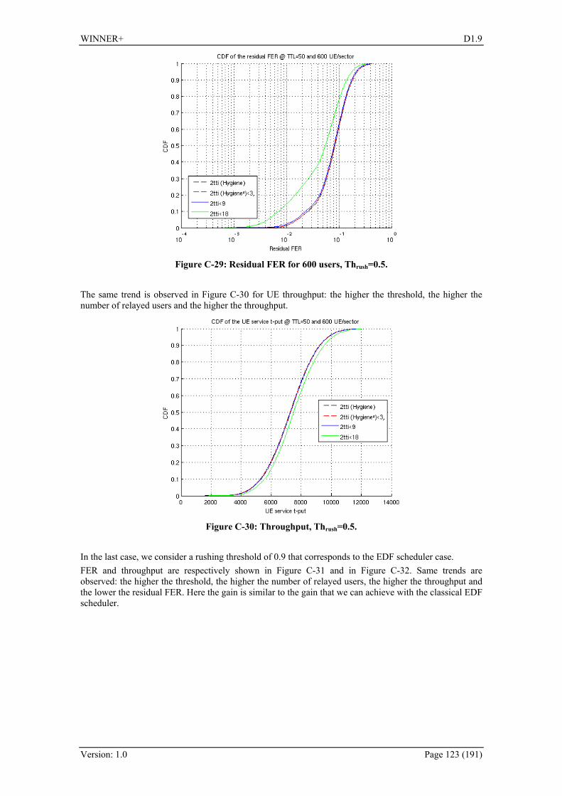
WINNER+ D1.9
Version: 1.0 Page 123 (191)
Figure C-29: Residual FER for 600 users, Thrush=0.5.
The same trend is observed in 338HFigure C-30 for UE throughput: the higher the threshold, the higher the number of relayed users and the higher the throughput.
Figure C-30: Throughput, Thrush=0.5.
In the last case, we consider a rushing threshold of 0.9 that corresponds to the EDF scheduler case. FER and throughput are respectively shown in 339HFigure C-31 and in 340HFigure C-32. Same trends are observed: the higher the threshold, the higher the number of relayed users, the higher the throughput and the lower the residual FER. Here the gain is similar to the gain that we can achieve with the classical EDF scheduler.

WINNER+ D1.9
Version: 1.0 Page 124 (191)
Figure C-31: Residual FER for 600 users, Thrush=0.9.
Figure C-32: Throughput, Thrush=0.9.
The relaying concept inside the Hygiene² scheduler improves performance of the system, in terms of residual FER, and UE throughput. However, the improvement becomes noticeable only when a significant number of users are relayed (relaying threshold = 18 dB). Performances were assessed considering non full buffer traffics (here VoIP). The different rushing thresholds highlight the trends of Hygiene² when it behaves like MCI, EDF+MCI or EDF only schedulers. We have observed that when the scheduler behaves as the combined EDF+MCI (rushing threshold 0.5), it outperforms all the presented results in terms of FER. Final step will be the investigation of the impact of HARQ on Hygiene² and to consider heterogeneous traffics. In these cases, we expect to observe an improvement due to relaying activation even when fewer users are relayed (relaying threshold = 3 or 9 dB).

WINNER+ D1.9
Version: 1.0 Page 125 (191)
D. Appendix – Innovations within Network Coding
D.1 Network Coding for Multiple-User Multiple-Relay Systems
D.1.1 Introduction The transmission links within the networks are modeled as independent quasi-static fading channels. This setting provides a general framework, encompassing previously investigated cases with only one relay. We propose to use linearly independent network codes for such scenario. Network codes are normally described by its encoding kernel, which denotes the linear relations between the source and the network codeword. For instance, two sources 1I and 2I , two codeword 1C and 2C with encoding kernel 1K
and 2K , respectively. Then, [ ]2111 , IIKC = and [ ]2122 , IIKC = . Then, 1C and 2C are linearly
independent, if 2K and 2K are linearly independent.
In particular, we investigate the performance of a class of deterministic network codes in such networks in terms of outage probabilities (to measure asymptotic performance with respective SNR: signal-to-noise ratio), and frame error rates. The former leads to theoretical performance limits constituting targets for practical schemes, while the latter provides for a performance measure for more practical settings.
Duplexing mode Half-Duplex Topology / links involved Relay enhanced cellular / uplink Network deployment Wide or local area Target system LTE-A History Refinement from D1.3 Field of main contribution Network coding
D.1.2 State of the Art Although the application of network coding to general relay networks is natural and clearly beneficial, most of previous schemes (e.g., [LJS06][YK07]) only consider two-source one-relay networks settings. In [YK07], coding for an effective two-user one-relay network was considered where the sources also act as relays. However, to increase system performance, multiple relays can be used within a cell. Thus, future cellular wireless networks can be modeled as multiple-user multiple-relay systems, as shown in 341HFigure 6-2. Surprisingly, design principles for using network coding in multiple-user multiple-relay networks are mostly unexplored. It is therefore valuable to study network coding schemes for such networks. So far only binary network coding schemes have been considered. However, as we shall show, binary network coding is generally suboptimal for MUMR wireless networks, at least for high SNRs (and quasi-static fading channels)..
D.2 Network coding for wireless broadcasting
D.2.1 Introduction
In a broadcast session a set of N information blocks iI , Ni ,....3,2,1= is to be broadcast from a BS to
a set of 1>M UEs. We assume the M BS-to-UE block-erasure channels to be independent with block-erasure probabilities iP , Mi ,...,2,1= , respectively. The transmission process is divided into two phases: the information transmission phase and the retransmission phase. In the information transmission phase, the BS broadcasts N information blocks, and during the transmission some blocks are lost over the respective BS-to- UE block-erasure channels. Each UE subsequently feeds back a packet with indices of the erased blocks, where we assume orthogonal and error-free feedback channels. A corresponding error matrix E is generated at the BS to record the blockerasure status reported by the UEs. The size of the error matrix is NM × , where 1, =jie if the j-th block of iUE is erased; otherwise, 0, =jie .
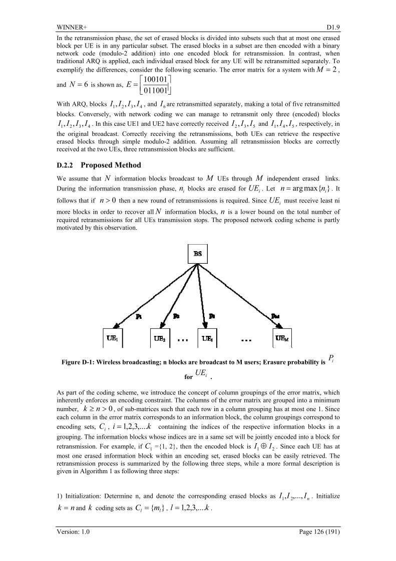
WINNER+ D1.9
Version: 1.0 Page 126 (191)
In the retransmission phase, the set of erased blocks is divided into subsets such that at most one erased block per UE is in any particular subset. The erased blocks in a subset are then encoded with a binary network code (modulo-2 addition) into one encoded block for retransmission. In contrast, when traditional ARQ is applied, each individual erased block for any UE will be retransmitted separately. To exemplify the differences, consider the following scenario. The error matrix for a system with 2=M ,
and 6=N is shown as, ⎥⎦⎤
⎢⎣⎡=011001100101E
With ARQ, blocks 4321 ,,, IIII , and 6I are retransmitted separately, making a total of five retransmitted blocks. Conversely, with network coding we can manage to retransmit only three (encoded) blocks
4321 ,,, IIII . In this case UE1 and UE2 have correctly received 532 ,, III and 541 ,, III , respectively, in the original broadcast. Correctly receiving the retransmissions, both UEs can retrieve the respective erased blocks through simple modulo-2 addition. Assuming all retransmission blocks are correctly received at the two UEs, three retransmission blocks are sufficient.
D.2.2 Proposed Method We assume that N information blocks broadcast to M UEs through M independent erased links. During the information transmission phase, in blocks are erased for iUE . Let maxarg inn = . It
follows that if 0>n then a new round of retransmissions is required. Since iUE must receive least ni
more blocks in order to recover all N information blocks, n is a lower bound on the total number of required retransmissions for all UEs transmission stops. The proposed network coding scheme is partly motivated by this observation.
Figure D-1: Wireless broadcasting; n blocks are broadcast to M users; Erasure probability is iP
for iUE .
As part of the coding scheme, we introduce the concept of column groupings of the error matrix, which inherently enforces an encoding constraint. The columns of the error matrix are grouped into a minimum number, 0>≥ nk , of sub-matrices such that each row in a column grouping has at most one 1. Since each column in the error matrix corresponds to an information block, the column groupings correspond to encoding sets, iC , ki ,....3,2,1= containing the indices of the respective information blocks in a grouping. The information blocks whose indices are in a same set will be jointly encoded into a block for retransmission. For example, if 1C =1, 2, then the encoded block is 21 II ⊕ . Since each UE has at most one erased information block within an encoding set, erased blocks can be easily retrieved. The retransmission process is summarized by the following three steps, while a more formal description is given in Algorithm 1 as following three steps:
1) Initialization: Determine n, and denote the corresponding erased blocks as nIII ,...,, 21 . Initialize
nk = and k coding sets as ll mC = , kl ,....3,2,1= .
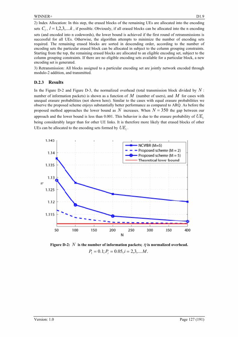
WINNER+ D1.9
Version: 1.0 Page 127 (191)
2) Index Allocation: In this step, the erased blocks of the remaining UEs are allocated into the encoding sets lC , kl ,....3,2,1= , if possible. Obviously, if all erased blocks can be allocated into the n encoding sets (and encoded into n codewords), the lower bound is achieved if the first round of retransmissions is successful for all UEs. Otherwise, the algorithm attempts to minimize the number of encoding sets required. The remaining erased blocks are sorted in descending order, according to the number of encoding sets the particular erased block can be allocated in subject to the column grouping constraints. Starting from the top, the remaining erased blocks are allocated to an eligible encoding set, subject to the column grouping constraints. If there are no eligible encoding sets available for a particular block, a new encoding set is generated. 3) Retransmission: All blocks assigned to a particular encoding set are jointly network encoded through modulo-2 addition, and transmitted.
D.2.3 Results In the 342HFigure D-2 and 343HFigure D-3, the normalized overhead (total transmission block divided by N : number of information packets) is shown as a function of M (number of users), and M for cases with unequal erasure probabilities (not shown here). Similar to the cases with equal erasure probabilities we observe the proposed scheme enjoys substantially better performance as compared to ARQ. As before the proposed method approaches the lower bound as N increases. When 350=N the gap between our approach and the lower bound is less than 0.001. This behavior is due to the erasure probability of 1UE being considerably larger than for other UE links. It is therefore more likely that erased blocks of other UEs can be allocated to the encoding sets formed by 1UE .
Figure D-2: N is the number of information packets; η is normalized overhead.
.,....3,2,05.0;1.01 MiPP i ===

WINNER+ D1.9
Version: 1.0 Page 128 (191)
Figure D-3: M is the number of user terminals. η is the normalized overhead.
MiPPN i ,...,3,2,05.0;1.0;100 1 ====
D.3 Application of MIMO and network coding in two-way relaying
D.3.1 Introduction In the recent years network coding has become one of the most promising ideas aiming at improving communication network throughput. Its development started from the seminal paper by Alswede et al [ALY00]. Soon the idea has come to attention of scientists and engineers resulting in hundreds of papers and a few valuable books [FS07,HL08,Yeu08]. Classical network coding is performed on the binary blocks (packets) in the network layer and can be considered as an alternative or extension to routing. A newer idea is to apply network coding directly in the physical layer [ZLL06], so it is performed rather on signal samples. This approach is currently intensively investigated (e.g. see [KPT09] and [ZL09]). In this section we will show a possible application of network coding in the upper part of the physical layer in which channel coding is considered. One of the frequent configurations occurring during information exchange in local or even macrocellular scenarios or is a two-way relaying. We will use this configuration to show that applying network coding with some additional tools leads to substantial savings in the system resources.
D.3.2 Application of network coding in two-way relaying Basic considerations Let us consider two-way relaying transmission on the example of a mobile (MS) and base station (BS) pair. The MS sends data blocks X1(n) to BS, whereas the BS transmits data blocks X2(n) to MS. Two duplexing methods are possible: FDD and TDD. We will consider the latter one applied in the LTE system. Thus, we assume that OFDMA is used in the downlink, whereas SC-FDMA is used in the uplink. Due to TDD duplexing and high carrier frequencies the transmission range may be rather limited, therefore a special technique has to be applied to extend the transmission range or to ensure the coverage at the appropriate quality. One of the possible solutions is the application of a relay station (RS) operating in an amplify-and-forward or decode-and-forward mode. Let us select the second type of relay stations for our considerations. First, let us consider a traditional two-way relaying TDD transmission between MS and BS via RS. In order to exchange data blocks between the MS and BS we need four time slots. For example, in the first slot the BS sends the data block to the RS which resends it to the MS in the second time slot. In the third time slot the MS sends its data block to the RS and in the fourth time slot the RS transfers it further to the BS.

WINNER+ D1.9
Version: 1.0 Page 129 (191)
It is well known that using traditional network coding performed in the network layer we are able to perform the data block exchange in three equivalent time slots. In the first time slot the MS sends the data block to the RS. In the second time slot the BS transmits its data block to the RS. In the third time slot the RS sends the modulo-2 sum of the received data blocks to both MS and BS. This phase of transmission is often called broadcasting phase. Thanks to buffering their own blocks both stations are able to calculate the remote station’s transmitted block by summing modulo-2 the received block with that one which has been sent by them. The general scheme of this operation is shown in 344HFigure D-4a.
a)
a
b
RS
RelaystationX (n)1
X (n)2
1
2
3
3
MS
BS
b)
a
b
RS
Relaystation
X (n)1
X (n)2
1
1
2
2
MS
BS
Figure D-4: Two-way relaying: with the application of RS and traditional network coding (a), with the application of RS and physical layer network coding (b). Further savings in the transmission time can be achieved if network coding is performed in the physical layer (see 345HFigure D-4b). One of the first reports on this kind of network coding is presented in [ZLL06]. In two-way relaying in which physical layer network coding is applied two time slots to exchange data blocks are needed. In the first time slot both the BS and MS send their data blocks to the RS. This transmission phase is called multiple access phase. The signals from the BS and MS are combined in the RS receive antenna. The RS appropriately interprets them as those representing the data block which is the modulo-2 sum of the data blocks received from both stations. Discussion on applicable signal constellations and their detection is a topic of [KPT09]. The block detected this way is subsequently broadcasted to the MS and BS which are able to decode the data block of the remote station knowing their own transmitted data blocks. This transmission phase is called broadcasting phase. In the original paper [ZLL06] it is assumed that the channel gains for the MS – RS as well as BS – RS links are equal and signals approaching the RS from the MS and BS are co-phased. Thus, in reality channel state information (CSI) would be required in both transmitters, which results in some loss of transmission efficiency. In [KPT09] these unrealistic assumptions are released, however, in both cases the RS generates data block by performing a symbol-by-symbol detection. Such an approach is certainly not optimal because typically channel coding is applied in transmission and through the hard decision process in the RS (even if the modulo-2 sum of the data blocks is detected only) a part of information on the transmitted data is lost. The immediate conclusion from our considerations is that channel coding applied in the transmission should be incorporated into the relaying process as well. Such an approach to the two-way relaying with traditional network coding performed in the RS has already been proposed in [LJS06]. We will further extend this idea. Proposed transmission scheme for two-way relaying Reducing time resources from four to two slots in exchanging data blocks between the MS and BS, as it is theoretically possible when physical layer network coding is applied, is a very attractive feature worth further exploitation. Recall again that in the downlink and uplink of the LTE different multiple access schemes are applied, so in the proposed transmission method in which our network coding is applied this fact has to be taken into account. The proposed solution is the following. In the multiple access time slot the MS transmits its data block in the SC-FDMA format, whereas the BS transmits concurrently its own data block in the OFDMA format. It has to be underlined that both stations use the same time and frequency slots belonging to the assigned channel. As we see, the MS which participates in the relaying process operates in the reversed direction as compared with other MSs which do not use relays in the uplink. This is our first assumption related to the proposed scheme. The RS jointly detects both data blocks using the MIMO technique. Assuming the use of at least two antennas by the RS we can interpret the transmission system as a virtual MIMO system in which out of two transmit antennas one is located in the MS and the other one is on the BS side. As it is shown in the sequel, it is possible to design a MIMO receiver which jointly detects OFDMA and SC-FDMA signals. The RS performs soft-decoding of the codewords transmitted by the MS and BS and finds information blocks transmitted by both stations. Subsequently, the modulo-2 sum of these information blocks is calculated and re-encoded. In the broadcasting time slot the RS transmits the produced codeword in the OFDMA format using the same frequency resources again. Here we set the second important assumption: the BS is

WINNER+ D1.9
Version: 1.0 Page 130 (191)
able to receive signals not only in the SC-FDMA, but also in the OFDMA mode. However, this assumption is very easy to be fulfilled. 346HFigure D-5 illustrates the idea of the proposed system.
a
b
RS
Relaystation
X (n)1
X (n)2
1
1
2
2
MS
BS
SC-FDMA
OFDMAOFDMA
OFDMA
Figure D-5: Proposed two-way relaying in the LTE with the application of MIMO and network coding in the RS.
Summarizing, in the proposed two-way relaying system the RS jointly detects individual signals sent by the BS and MS using the MIMO technique and broadcasts the codeword whose information block is the modulo-2 sum of the information blocks of the detected codewords. Proposed two-way relaying in the cellular scenario Since we have assumed that the MS participating in the two-way relaying via the RS in the multiple access phase operates in the reversed mode, it has to be shown that it does not create major interference problems to the other stations in the same and neighboring cells. Let us note that a typical frequency reuse factor in the LTE is equal to one in cell inner areas and can be equal to 1/n (e.g. n=3) in outer cell areas [DPSB08]. 347HFigure D-6 presents a typical frequency reuse pattern applied in the cells [DPS+08].
Terminals in the outer part of cell #3
Terminals in the outer part of cell #2
Terminals in the outer part of cell #1
Terminals in the inner part of the cell
Reduced power
Figure D-6: Possible frequency planning in LTE cells (quoted after [DPS+08]). Since the basic aim of relaying is to extend the transmission range, we assume that the RS is located in the outer cell ring and the MS cooperating with it is placed in the same part of the cell as well. 348HFigure D-7 shows these two stations and some other mobile stations potentially suffering from interference in the same and neighboring cells.
Figure D-7: Cellular scenario in two-way relaying with the RS – the MS operates in the time slot reversed mode.
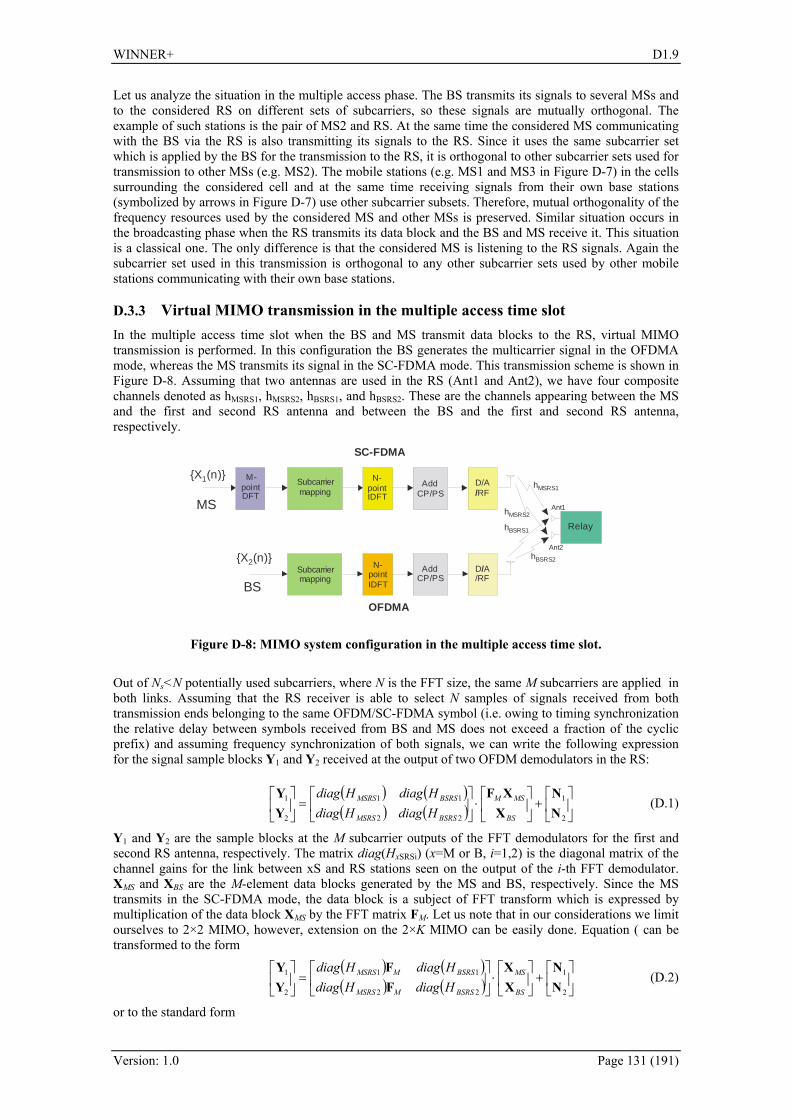
WINNER+ D1.9
Version: 1.0 Page 131 (191)
Let us analyze the situation in the multiple access phase. The BS transmits its signals to several MSs and to the considered RS on different sets of subcarriers, so these signals are mutually orthogonal. The example of such stations is the pair of MS2 and RS. At the same time the considered MS communicating with the BS via the RS is also transmitting its signals to the RS. Since it uses the same subcarrier set which is applied by the BS for the transmission to the RS, it is orthogonal to other subcarrier sets used for transmission to other MSs (e.g. MS2). The mobile stations (e.g. MS1 and MS3 in 349HFigure D-7) in the cells surrounding the considered cell and at the same time receiving signals from their own base stations (symbolized by arrows in 350HFigure D-7) use other subcarrier subsets. Therefore, mutual orthogonality of the frequency resources used by the considered MS and other MSs is preserved. Similar situation occurs in the broadcasting phase when the RS transmits its data block and the BS and MS receive it. This situation is a classical one. The only difference is that the considered MS is listening to the RS signals. Again the subcarrier set used in this transmission is orthogonal to any other subcarrier sets used by other mobile stations communicating with their own base stations.
D.3.3 Virtual MIMO transmission in the multiple access time slot In the multiple access time slot when the BS and MS transmit data blocks to the RS, virtual MIMO transmission is performed. In this configuration the BS generates the multicarrier signal in the OFDMA mode, whereas the MS transmits its signal in the SC-FDMA mode. This transmission scheme is shown in 351HFigure D-8. Assuming that two antennas are used in the RS (Ant1 and Ant2), we have four composite channels denoted as hMSRS1, hMSRS2, hBSRS1, and hBSRS2. These are the channels appearing between the MS and the first and second RS antenna and between the BS and the first and second RS antenna, respectively.
OFDMA
Subcarriermapping
N-pointIDFT
AddCP/PS
D A/RF
/
Relay
SC-FDMA
Subcarriermapping
M-pointDFT
N-pointIDFT
AddCP/PS
D/ARF/
X (n)1
X (n)2
MS
BS
hMSRS1
hBSRS1
hMSRS2
hBSRS2
Ant1
Ant2
Figure D-8: MIMO system configuration in the multiple access time slot. Out of Ns<N potentially used subcarriers, where N is the FFT size, the same M subcarriers are applied in both links. Assuming that the RS receiver is able to select N samples of signals received from both transmission ends belonging to the same OFDM/SC-FDMA symbol (i.e. owing to timing synchronization the relative delay between symbols received from BS and MS does not exceed a fraction of the cyclic prefix) and assuming frequency synchronization of both signals, we can write the following expression for the signal sample blocks Y1 and Y2 received at the output of two OFDM demodulators in the RS:
( ) ( )( ) ( ) ⎥
⎦
⎤⎢⎣
⎡+⎥
⎦
⎤⎢⎣
⎡⋅⎥
⎦
⎤⎢⎣
⎡=⎥
⎦
⎤⎢⎣
⎡
2
1
22
11
2
1
NN
XXF
YY
BS
MSM
BSRSMSRS
BSRSMSRS
HdiagHdiagHdiagHdiag
(D.1)
Y1 and Y2 are the sample blocks at the M subcarrier outputs of the FFT demodulators for the first and second RS antenna, respectively. The matrix diag(HxSRSi) (x=M or B, i=1,2) is the diagonal matrix of the channel gains for the link between xS and RS stations seen on the output of the i-th FFT demodulator. XMS and XBS are the M-element data blocks generated by the MS and BS, respectively. Since the MS transmits in the SC-FDMA mode, the data block is a subject of FFT transform which is expressed by multiplication of the data block XMS by the FFT matrix FM. Let us note that in our considerations we limit ourselves to 2×2 MIMO, however, extension on the 2×K MIMO can be easily done. Equation ( can be transformed to the form
( ) ( )( ) ( ) ⎥
⎦
⎤⎢⎣
⎡+⎥
⎦
⎤⎢⎣
⎡⋅⎥
⎦
⎤⎢⎣
⎡=⎥
⎦
⎤⎢⎣
⎡
2
1
22
11
2
1
NN
XX
FF
YY
BS
MS
BSRSMMSRS
BSRSMMSRS
HdiagHdiagHdiagHdiag
(D.2)
or to the standard form

WINNER+ D1.9
Version: 1.0 Page 132 (191)
[ ] ⎥⎦
⎤⎢⎣
⎡+⎥
⎦
⎤⎢⎣
⎡⋅=⎥
⎦
⎤⎢⎣
⎡
2
1
2
1
NN
XX
HYY
BS
MS (D.3)
where
( ) ( )( ) ( )⎥⎦
⎤⎢⎣
⎡=
22
11
BSRSMMSRS
BSRSMMSRS
HdiagHdiagHdiagHdiag
HFF
(D.4)
It is well known that the MMSE solution of equation (D.3) is
[ ]⎥⎥⎦
⎤
⎢⎢⎣
⎡=
⎥⎥⎦
⎤
⎢⎢⎣
⎡⎥⎦
⎤⎢⎣
⎡⋅=
⎥⎥⎦
⎤
⎢⎢⎣
⎡ −
)~()~(
ˆˆ
,~~
2
11
BS
MS
BS
MSHH
BS
MS
decdec
XX
XX
YY
HHHXX (D.5)
whereas the ML solution is
[ ]2
2
1
,minargˆ
ˆ⎥⎦
⎤⎢⎣
⎡⋅−⎥
⎦
⎤⎢⎣
⎡=
⎥⎥⎦
⎤
⎢⎢⎣
⎡
BS
MS
BS
MS
BSMS XX
HYY
XX
XX (D.6)
Since the ML solution, especially for multilevel QAM modulations applied in XMS and XBS, is computationally infeasible, some kind of a suboptimum algorithm would be advantageous as our first simulation experiments showed that the MMSE algorithm results in an insufficient detection quality. Suboptimum ML MIMO detector The idea of the proposed suboptimum ML MIMO detector is similar to that presented in [KDT09], however, it differs from it due to the necessity of application of high order QAM modulations. For simplicity of our notation let us denote
⎥⎦
⎤⎢⎣
⎡=⎥
⎦
⎤⎢⎣
⎡=
BS
MS
XX
XYY
Y ,2
1 (D.7)
First the detector finds a tentative solution using e.g. the MMSE criterion and applying (D.5) (the ZF solution is also applicable). In this way the set of tentative decisions XMMSE=X0 is found. In order to find the final decisions, the following error is minimized
( ) ( )HaYHaYaXHY −−=+−= ddE HMMSE
2)( (D.8)
where MMSEd XHYY ⋅−= . Let us denote the initial error as 000 YY ddE H= , where 00 XHYY ⋅−=d . The symbol a denotes the vector of data symbol corrections with respect to the current tentative solution (e.g. X0=XMMSE). After finding XMMSE=X0 the next detection step is an effective selection of the correction vector a. We perform the following steps of the algorithm. • We iteratively improve our decision Xn+1 by selecting a single most probable symbol out of the whole
vector Xn. At the starting moment the correction vector is a=0. The most probable symbol Xn,i (i=1,…,2M) to be corrected is that one for which the element of the gradient of the error E with respect to the correction vector a has the highest magnitude. In order to perform this step we find from (D.8) that
[ ] HaHaYHaYY HHn
HHn
Hnn dddΕ +−=+ Re21 (D.9)
so the gradient of En+1 with respect to a is
nHHn d
ddE YHHaH
a−=+1 (D.10)
However, at the beginning a=0, so the gradient reduces to the form
01 where, YHpp
ad
ddE H=−= (D.11)
Therefore we find the index of the entry of p featuring the highest magnitude
[ ]TMii pppi 21max ,...,where,maxarg == p (D.12)
As a result, the imax-th vector entry max,inX is a candidate for change.
• The most probable corrections of the tentative decision occur by moving our decision to one of the neighboring constellation points. For each constellation point j (j=1,…,Mconst, where Mconst is the size

WINNER+ D1.9
Version: 1.0 Page 133 (191)
of the QAM constellation) we can define and store the potential corrections cj=[cj,1,…,cj,L] in the look-up table. Its size and, in consequence, the number of required operations of the algorithm depends on how many neighboring points are taken into account as potential final decisions by the designer. 352HFigure D-9 shows an example of possible corrections for the selected tentative constellation point. The point x denotes the received sample Yi of the vector Y=[Y1,…,YM,YM+1,…,Y2M]T. For the exemplary constellation point )3,1(− shown in 353HFigure D-9 the correction block has been selected to be
[ ]]2,2,2 jc j −−= . Out of L possible corrections for the signal max,inX we select that one for which the
projection of the gradient element maxip on the vectors of possible corrections has the largest
magnitude and the projected vector has the same direction as the direction of the correction vector. For example, the correction selected for the point )3,1(− in 354HFigure D-9 is –2. In the formal notation we perform the following operation
Llcpl liil ,...,1,Remaxarg *,max maxmax
== (D.13)
Thus, the resulting correction candidate vector is Tlic ]0,...,0,,0,...,0[maxmax ,=a . Let us note that we have
calculated of the gradient of E treating the error E as a continuous function of the correction block a, however, a can take only discrete values. Therefore we have to check if the error E is really decreased if the determined correction element is applied. If it is not, the decision block remains unchanged. In general, we calculate
[ ] [ ]maxmaxmaxmaxmax
2*1 Re2Re2 i
Hiiiin
HHHnn apaEEE hhHaHapa +−=+−=+ (D.14)
where hi is the i-th column of the channel matrix H. The new decision block is Xn+1=Xn+a and we can treat it is a new tentative decision.
I
QMMSE tentative decision ( 1,3)−
Candidates forthe final decision
The largestprojection
− −3 1 1 3
1
3
Figure D-9: Example of selection of the potential correction for the tentative symbol (-1,3). • In order to proceed to the next iteration in which we determine the next symbol candidate for change,
we have to find the new vector of difference between the received block and the hypothetical channel output
( )maxmax11 iinnnnn addd hYaHYaXHYXHYY −=⋅−=+⋅−=⋅−= ++ (D.15)
The new gradient vector pn+1 can also be calculated on the basis of the previous one according to the formula
maxmaxmaxmax)(11 i
Hiniin
Hn
Hn aadd hHphYHYHp −=−== ++ (D.16)
Let us note that typically the column of the channel matrix such as hi contains mostly zeros and only a small number of its elements has a non-zero value. This is not true if hi is associated with the SC-FDMA part of the channel matrix.
• Knowing the gradient pn+1 and the new error En+1 we can start the next iteration finding a new candidate data symbol to change. Thus, we repeat the above steps till the assumed maximum number of data symbols for potential correction is reached.
After determining the final decision block X , the soft decisions have to be produced in order to enable soft-decision decoding of the FEC codewords. Let us note that as a result of finding the final decision we also have at the disposal the following vector
XHYY ˆˆ ⋅−=d (D.17)

WINNER+ D1.9
Version: 1.0 Page 134 (191)
Basically two methods of LLR calculations are possible. A much simpler, but the suboptimum one has been used in our simulation experiments. For each constellation point Xm representing the K-bit block we predefine and store the K-element table of constellation points kmX ,
~ , which are the closest to the point Xm and differ on the k-th bit.
At the beginning of derivation of the approximate LLR value for each bit associated with the elements of the vector of detected symbols X , we calculate the constant part of the soft measures in the form
YY ˆˆ dd Hconst =λ (D.18)
Let us note that constλ is practically known from the last iteration of searching for the final decision block
X and it is in fact the final error E. It is the part of the soft measure associated with the distance of all detected constellation points to the vector Y of the received samples.
For each symbol )2,...,1(ˆ MiX i = belonging to the detected data block X representing the K-bit block ),...,,( ,2,1, Kiiii bbb=b we perform the following operations
• For each bit bi,k (k=1,…,K) we find the soft-decision metric from the formula
( ) ( )( )constkiH
kikiki ddb λλ −−= ,,,, '')1ˆ2( YY (D.19)
where ( ) kid ,'Y is the error vector differing from the original vector Yd by the application of kiX ,~
instead of iX on the i-th position in the symbol block. It can be calculated from the formula
( ) ( ) ikiiki XXdd hYY ⋅−−= ,,~ˆˆ' (D.20)
We see that rather simple calculations allow us to determine the approximate LLR values needed for FEC soft-input correction. Other operations performed in the multiple access phase As we know, in the LTE system a turbo code is applied. After collecting the appropriate number of LLR soft metrics needed to decode the whole data blocks received from the MS and BS, both codewords are determined by the appropriate turbo code decoders resulting in two blocks of information bits sent by the MS and BS.
D.3.4 Transmission in the broadcasting phase At the beginning of the broadcasting phase the RS determines the modulo-2 sum of the information bit blocks. Subsequently the codeword is calculated in the turbo code encoder and its bits are mapped onto data symbols of the appropriate number of the OFDM symbols. The RS broadcasts the produced OFDM symbols in the OFDMA mode to the MS and BS using the same frequency resources as in the multiple access phase. As we see, although the BS typically receives signals in the SC-FDMA mode it must be able to receive OFDM signals as well. The MS and BS receive the transmitted signals, decode it using the decoder of the applied turbo code and, as a result, determine the modulo-2 sum of the information blocks from BS and MS. Having their own information blocks stored in their buffers, both stations are able to determine the other station’s information block by summing modulo-2 the decoded block with the own one. Since the RS inherently uses at least two antennas in the multiple access mode, they can be applied in the broadcasting mode as well in the MISO or MIMO configuration depending on the capabilities of the MS and BS participating in the two-way relaying process.
D.3.5 Simulation experiment In order to check the concept of two-way relaying with network coding and MIMO applied in the relay station, the simulation experiment was performed. Two-way relaying in the system with basic features of the LTE system was modelled. As already mentioned, multicarrier transmission in the TDD mode between BS and MS and vice versa with the RS between them was simulated. Out of many possible configurations of the LTE system the FFT size equal to 512 was selected. 16-QAM was applied in both transmission directions in which OFDM and SC-FDMA symbols are generated. Since in the LTE system several sizes of subcarrier blocks can be applied, M=16 and 32 subcarriers out of 300 possible ones were selected for the two-way relaying between the considered MS and the BS. Four different channel characteristics were set: two for the MS – RS transmission and two others in the BS – RS direction. For simplicity of the simulation stationarity of the channels and their perfect knowledge in the receivers were assumed. Based on the properties of the channels between RS and BS, the BS decides which set of

WINNER+ D1.9
Version: 1.0 Page 135 (191)
subcarriers is to be assigned to this transmission. The selection criterion was the maximization of the subsequent M squares of the magnitudes of the channel gains. 355HFigure D-10 shows the channel characteristics and the range of subcarrier frequencies selected for transmission.
Figure D-10: Amplitude characteristics of the channels between BS and RS and between MS and RS.
For the broadcasting phase channel reciprocity and MISO transmission were assumed. We tested the two-way relaying with the LTE turbo code with the coding rate R=1/3 and the information block length as well as the internal interleaver depth KI equal to 504 and 1504. A certain number of pseudorandom bits was added at the end of the transmitted codewords to fill the gap between the length of the codeword and the number of bits carried by a certain number of OFDM/SC-FDMA symbols in which 16 or 32 16-QAM modulated subcarriers are used. Recall that for the R=1/3 turbo code the length of the FEC codewords is 3×504+12=1524 or 3×1504+12=4524, respectively. For the given channel models and the assumed system configuration the performance of all the component links was estimated. These links were the links from MS to RS, from BS to RS and vice versa. As already mentioned, in the multiple access phase the suboptimum ML MIMO receiver was applied in the RS, whereas in the transmission from the RS to the BS and MS the MISO transmission with the Alamouti code was implemented. 356HFigure D-11 presents the BER plots on the output of the turbo code decoder when the information block length and the turbo code interleaver length were equal to 504 and 16 subcarrier OFDM/SC-FDMA blocks were applied.
4 4.5 5 5.5 6 6.5 7 7.510-5
10-4
10-3
10-2
10-1
100
SNR [dB]
BE
R o
n th
e de
code
r out
put
BER for turbo coded transmission (k=504, R=1/3, 16 subcarriers)
RS->MSRS->BSMS->RSBS->RS
Sub-ML MIMO
MISO with Alamouti code
Figure D-11: Performance of the component links between MS and BS with the relay station.

WINNER+ D1.9
Version: 1.0 Page 136 (191)
The performance of the whole links between the MS and BS and vice versa is shown in 357HFigure D-12. The quality of the whole links in the broadcasting phase is virtually determined by the MISO transmission.
4 4.5 5 5.5 6 6.5 7 7.510-4
10-3
10-2
10-1
100
SNR [dB]
BER
on
the
deco
der o
utpu
t
BER for turbo coded transmission (k=504, R=1/3, 16 subcarriers)
MS->BSBS->MS
Figure D-12: Performance of two-way relaying for the transmission using 16 subcarrier blocks and
R=1/3 LTE turbo code.
Similar results were received for the longer data block KL=1504 bits when 32 subcarrier blocks are applied in the two-way relaying. The estimated BER curves are shown in 358HFigure D-13 and 359HFigure D-14. Again the MISO links determine the overall link quality. Clearly the application of the MIMO technique in both directions from the RS to the BS and MS would considerably improve the end-to-end system performance.
4 4.5 5 5.5 6 6.5 710-4
10-3
10-2
10-1
100
SNR [dB]
BER
on
the
deco
der o
utpu
t
BER for turbo coded transmission (k=1504, R=1/3, 32 subcarriers)
RS->MSRS->BSMS->RSBS->RS
MISO Alamouti code
Sub-ML MIMO
Figure D-13: Performance of the component links between MS and BS with relay station.

WINNER+ D1.9
Version: 1.0 Page 137 (191)
4 4.5 5 5.5 6 6.5 710-4
10-3
10-2
10-1
100
SNR [dB]
BE
R o
n th
e de
code
r out
put
BER for turbo coded transmission (k=1504, R=1/3, 32 subcarriers)
MS->BSBS->MS
Figure D-14: Performance of two-way relaying for the transmission using 32 subcarrier blocks and R=1/3 LTE turbo code.
D.3.6 Conclusions The effective method of information exchange between two stations (e.g. the BS and MS) with the application of a relay station, the so-called two-way relaying, has been proposed. Contrary to the two-way relaying without network coding in which in the TDD mode four time slots (or transmission phases) are needed, in the proposed solution only two time slots are necessary – the multiple access and broadcasting ones. This result has been achieved thanks to the application of network coding and MIMO technique in the multiple access phase in the RS. In the transmission scheme network coding is performed on the decoded information blocks rather than directly on the physical signals or uncoded bits. This results in a high performance of each constituent link which leads to the overall high performance. In order to achieve a low BER level in the transmission from the BS and MS to the RS, the suboptimum ML detection algorithm has been proposed for detection of MIMO signals. Its performance is significantly better than the performance of the MMSE MIMO receiver. It is worth noting that the RS MIMO receiver is able to detect signals simultaneously transmitted in the OFDMA and SC-FDMA modes. Contrary to the pure physical network coding, the conditions necessary for the transmission systems to operate are easily achievable. It is only assumed that the MS is allowed to work in the time reversed mode (i.e. it transmits when other MSs receive and vice versa) and the BS is able to simultaneously receive the signals with different subcarrier blocks modulated both in OFDMA and SC-FDMA mode.

WINNER+ D1.9
Version: 1.0 Page 138 (191)
E. Appendix – Innovations within Advanced Antenna Schemes
E.1 UL-MIMO Schemes in WiMAX Systems
E.1.1 Introduction In order to fulfill the WiMAX promises, WiMAX semiconductor platforms are providing solutions for all types of WiMAX equipment makers and service providers in different markets. However, to meet the requirements of extended coverage, high data rate, and low power consumption, silicon solutions need to deliver some challenging tradeoffs presented by these key constraints. In WiMAX systems, as in other wireless systems, the uplink channel becomes the limiting factor for coverage. Improving the uplink performance yields benefits for both operators and end users; it lowers infrastructure costs and improves user experience. Typically in current WiMAX systems, MIMO (multiple input multiple output) is implemented on only the downlink channel (see D1.7 [WIN+D17] for more detailed discussion). Uplink MIMO, the implementation of dual transmit channels in a single user terminal, is one of the WiMAX capabilities that can improve uplink performance. Moreover, if an appropriate algorithm is used in implementing the second transmit channel, substantial improvement can be achieved with little or no incremental cost to the mobile station and no cost at all to the base station. In this section, we provide the benefits of UL-MIMO together with a new method, namely, tile-switched diversity (TSD), which benefits from transmit diversity without any channel knowledge at the transmitter side. This method is mainly based on the transmit diversity concept for clustered OFDM systems which is first introduced in [CDS96]. The idea has been developed for WiMAX systems and its advantages has been shown based on both performance analysis and implementation aspects. As described in the sequel, the presented innovation is completely transparent and it does not require any additional processing at the base station side. This makes the algorithm very attractive for mobile stations from the implementation point of view.
Applicability Comment Duplexing mode FDD/TDD FDD, TDD Link (UL/DL) UL Usage and deployment and usage scenario (hot spot, micro-cellular, macro-cellular)
Wide or local area
Topology Conventional cell Support for relays Not considered CSIT requirements CSIT not needed Field of main contribution UL transmit diversity transparent to
base station
E.1.2 Proposed innovation: Tile-Switched Diversity The presented technique uses the basic idea of antenna selection and benefits from the frequency selectivity of the channel by means of channel coding. It requires the implementation of two transmit antennas at the mobile station but is fully transparent to the base station like cyclic delay diversity (CDD) transmission. However, compared to CDD transmission, it has better or equal performance in fading environments and significantly better performance in environments with a line-of-sight. In a typical WiMAX system [IEEE16e05], tiles are defined as the minimum resource allocation unit for uplink transmission. A tile consists of 4 subcarriers and extends over 3 OFDMA symbols. In TSD, tiles from data slots are split between the two transmit antennas of the mobile station. In particular, each uplink slot (defined as the group of 6 tiles) is split in two groups of three tiles. Each group of tiles goes to a different transmit antenna, and, therefore, each group of tiles is affected by a different channel. This transmission technique is completely transparent to the base station, as the channel estimation is done on a tile-by-tile basis. It is worth noting that the presented TSD scheme may be applied to PUSC (namely, partial usage of subchannels) permutation in the UL which uses the notion of tile shown in 360HFigure E-1. Specifically, PUSC is defined as the permutation type in the specification which benefits from the
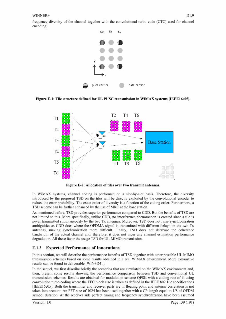
WINNER+ D1.9
Version: 1.0 Page 139 (191)
frequency diversity of the channel together with the convolutional turbo code (CTC) used for channel encoding.
Figure E-1: Tile structure defined for UL PUSC transmission in WiMAX systems [IEEE16e05].
Figure E-2: Allocation of tiles over two transmit antennas.
In WiMAX systems, channel coding is performed on a slot-by-slot basis. Therefore, the diversity introduced by the proposed TSD on the tiles will be directly exploited by the convolutional encoder to reduce the error probability. The exact order of diversity is a function of the coding order. Furthermore, a TSD scheme can be further enhanced by the use of MRC at the base station. As mentioned before, TSD provides superior performance compared to CDD. But the benefits of TSD are not limited to this. More specifically, unlike CDD, no interference phenomenon is created since a tile is never transmitted simultaneously by the two Tx antennas. Moreover, TSD does not raise synchronization ambiguities as CDD does where the OFDMA signal is transmitted with different delays on the two Tx antennas, making synchronization more difficult. Finally, TSD does not decrease the coherence bandwidth of the actual channel and, therefore, it does not incur any channel estimation performance degradation. All these favor the usage TSD for UL-MIMO transmission.
E.1.3 Expected Performance of Innovations In this section, we will describe the performance benefits of TSD together with other possible UL MIMO transmission schemes based on some results obtained in a real WiMAX environment. More exhaustive results can be found in deliverable [WIN+D41]. In the sequel, we first describe briefly the scenarios that are simulated on the WiMAX environment and, then, present some results showing the performance comparison between TSD and conventional UL transmission schemes. Results are obtained for modulation scheme QPSK with a coding rate of ½ using convolution turbo coding where the FEC block size is taken as defined in the IEEE 802.16e specifications [IEEE16e05]. Both the transmitter and receiver parts are in floating point and antenna correlation is not taken into account. An FFT size of 1024 has been used together with a CP length equal to 1/8 of OFDM symbol duration. At the receiver side perfect timing and frequency synchronization have been assumed
t
f

WINNER+ D1.9
Version: 1.0 Page 140 (191)
and a soft output equalizer with a bit de-interleaver and a soft-input CTC decoder are used. For AWGN channel the perfect channel estimation corresponds to the case where the channel estimation module is disabled. In the figures, both the perfect CSI results and results with channel estimation are presented. The results are depicted as packet error rate (PER) vs C/N where one packet contains only one FEC block and C/N denotes the received signal-to-noise ratio per subcarrier per receive antenna. 361HFigure E-3 depicts the performance comparison on AWGN. In particular, we have the performances of MRC alone (i.e., 2 antennas at the receiver side), STC (i.e., Alamouti scheme) with MRC, UL TSD with MRC and UL CDD with MRC with a cyclic delay of 6 samples. It is worth noting that in the following figures, the delay for CDD has been chosen as the one giving the overall best performance. We can see that when the channel information is perfectly available at the receiver, MRC only, STC and TSD provide the same performance as expected. However, CDD has 2 dB performance degradation compared to the others for a PER of 10-3. This simply implies that TSD does not degrade the performance in AWGN channel which is not the case for CDD transmission. On the other hand, when we enable the channel estimation module CDD has an additional 1 dB degradation compared to MRC alone and TSD schemes. Moreover, since the number of pilots are half in STC transmission that of TSD, STC suffers from 1 dB performance degradation.
-6 -4 -2 0 2 4 6 81,00E-006
1,00E-005
1,00E-004
1,00E-003
1,00E-002
1,00E-001
1,00E+000
AWGN - QPSK 1/2
MRC – Rx perfect CSIMRC – Rx floatSTC + MRC – Rx perfect CSISTC + MRC – Rx floatUL CDD + MRC – Rx per-fect CSIUL CDD + MRC – Rx floatUL TSD + MRC – Rx per-fect CSIUL TSD + MRC – Rx float
C/N
PER
Figure E-3: PER comparison in AWGN channel.
362HFigure E-4 compares the performances of MRC only, STC, TSD and CDD on the ITU pedestrian channel model B. In this figure, SISO performance is also added as a reference in which only one receive antenna is used while all the other schemes are simulated with two receive antennas. It can be observed that both TSD and CDD bring an important diversity gain that will noticeably enhance the system performance when the channel knowledge is perfectly known at the receiver. Indeed, they provide 2 dB gain at the PER of 10-3 compared to MRC only transmission with a slight complexity increase at the transmitter side. However, the performance of TSD and CDD seem not as efficient as that of STC. This is actually the case with perfect CSI and when we include the channel estimation errors TSD and CDD provide almost the same performance as STC and better than MRC only transmission. Consequently, in fading channels the principle gain of both transparent techniques, i.e., TSD and CDD, is better than MRC only transmission and remains similar to STC transmission which requires specific implementation at the receiver side. Moreover, on a typical vehicular channel representing mobile terminals, the conclusions remain unchanged.
2 dB
3 dB

WINNER+ D1.9
Version: 1.0 Page 141 (191)
-4 -2 0 2 4 6 8 101,00E-004
1,00E-003
1,00E-002
1,00E-001
1,00E+000
Ped B 3 km/h - QPSK 1/2
MRC – Rx perfect CSIMRC – Rx floatSTC + MRC – Rx perfect CSISTC + MRC – Rx floatUL CDD + MRC – Rx per-fect CSIUL CDD + MRC – Rx floatUL TSD + MRC – Rx per-fect CSIUL TSD + MRC – Rx floatSISO – Rx perfect CSI
C/N
PER
Figure E-4: PER comparison in ITU pedestrian B channel at 3 km/h.
E.1.4 Potential Impacts on Signalling Presented UL-MIMO schemes TSD and CDD do not require additional signalling. In addition, the TSD method does not require any specific decoder mechanism at the base station side and it is completely a transparent scheme to the base station for UL transmission.
E.1.5 Potential Impacts on Architecture 363HFigure E-5 illustrates a typical mobile station RF front-end design. It is worth noting that passive components for power supply decoupling are omitted for the sake of clarity. The blocks depicted in green are the main components of a 1Tx/2Rx mobile station. On the other hand, the blocks in orange are the additional components for a 2Tx/2Rx mobile station. In particular, the required components to realize the second transmit antenna path are simply a second power amplifier, ordinary filters and duplexer.
Figure E-5: Typical mobile station RF front end.
SPDT ANT _ A
PM8800WiZIRD
2T2R RFICTransceiver
Baseband I / Q Interface
SPI Control
BPFPALPF
BPF
SPDT ANT _ B
Balun
BPFPALPF
BPF Balun
Crystal
Rx A
Tx A
Rx B
Tx B
Additional components for second transmit path

WINNER+ D1.9
Version: 1.0 Page 142 (191)
The additional size required for these components is approximately 50 mm2. Actually, this may vary depending on the components chosen but the order gives the size which can be achieved without considering the recent advances in the component design. Indeed, in the future, this could even be smaller, as integrated front-end modules (FEM) are used. Note that some FEM vendors are planning integrated dual-FEM designs in a single package. This process would further reduce the impact of the second transmitter. Similarly, it is difficult to provide exact price estimates due to variable vendor pricing. Nevertheless, we estimate the added cost of the second transmitter in this case to be about $2 in 500K volumes.
E.1.6 Compatibility to LTE and LTE-Advanced Since the presented concept is transparent to the base station in uplink transmission, it can be equally applied to systems with the similar impacts on the architecture. However, the study has been limited to WiMAX systems and the compatibility of the presented concept needs further investigation for LTE and LTE-Advanced.
E.1.7 Conclusions UL-MIMO techniques are introduced in the standards to provide additional gains on the uplink link budget compared to single transmit antenna schemes. In addition to the STC based on Alamouti scheme, the current WiMAX specifications include CDD as the transparent UL transmission technique. Although this technique does not require specific detection mechanism at the base station, it suffers from performance loss in line of sight channels. In this contribution, we present an alternative transparent transmission technique which has similar performance to CDD in channel conditions where CDD is thought to perform well and does not suffer from performance loss as CDD in specific channel conditions. Moreover, we have studied the effect of second transmit antenna in the front-end design and shown that it is feasible to realize second transmission path in mobile stations with a small cost increase.
E.2 Joint channel estimation and decoding using Gaussian approximation in a factor graph for OFDM
E.2.1 Introduction Propagating messages in a suitable factor graph using a belief propagation (BP) algorithm is a systematic tool for deriving iterative algorithms. For channel estimation, BP has to handle continuous variables, namely the channel coefficients. In the literature, canonical distributions are used for quantizing probability distributions, in order to propagate discrete probability distributions. However, the degree of quantization has a strong impact on estimation accuracy and performance. In D1.7, instead of relying on quantization, we introduced a new proposal which is to model probability distributions as mixtures of Gaussian distributions. It allows for estimation improvement and complexity reduction simultaneously. The algorithm uses the Gaussian approximation for downward and upward messages and is named BP with downward and upward Gaussian approximation (BP-DUGA). In D1.7, we focused on BP with Gaussian approximation over a multipath channel, using single-carrier modulation. Here, we extend the concept to multi-carrier modulations.
Applicability Comment Duplexing mode FDD/TDD FDD or TDD Link (UL/DL) Any point-to-point link Usage and deployment and usage scenario (hot spot, micro-cellular, macro-cellular)
Any
Topology Any Support for relays Not considered CSIT requirements Depending on transmit scheme Field of main contribution Signal processing in the receiver
E.2.2 System Model We consider a coded orthogonal frequency division multiplexing (OFDM) signal transmitted over a
single-input single-output (SISO) frequency-selective channel as shown in 364H

WINNER+ D1.9
Version: 1.0 Page 143 (191)
Figure E-6. An information binary sequence S is encoded into a coded sequence C. The encoded bits are then interleaved by a pseudo-random interleaver and modulated. After pilot insertion, the obtained sequence X = (X0, …, XN-1)T is processed by an inverse fast Fourier transform (IFFT), which provides the time-domain sequence x = (x0, …, xN-1)T = U†X, where U is the normalized N×N FFT matrix and (.)† stands for transpose-conjugate. After insertion of a cyclic prefix (CP) with length LCP, the transmitted OFDM symbol is
( )TT1,,,'
CPxx −−= NLN xx L .
The received sequence is
( )T10 CP
',,'' −+= LNyy Ly
with
∑−
=− −+≤≤+=
1
0CP 10,''
L
lklklk LNknxhy ,
where L is the number of taps in the channel, L ≤ LCP, h = (h0, …, hL-1)T is the channel impulse response, and nk is a complex Gaussian noise with zero mean and variance 2σ2. After CP removal, the received time domain sequence y = (y0, …, yN-1)T is processed by FFT. The received sequence in the frequency domain is Y = (Y0, …, YN-1)T = Uy. We assume that the channel impulse response is constant over one OFDM symbol and use the well-known OFDM discrete-time model
Y = diag(H)X + N, (E.1)
where N = (N0, …, NN-1)T = Un has the same distribution as n = (n0, …, nN-1)T, H = (H0, …, HN-1)T represents the channel frequency-response H = Ωh, where the N×L matrix Ω is built from the L first columns of U, and diag(H) represents a diagonal matrix with Hk as its (k,k) entry. Finally, in order to obtain the estimated binary information data , the sequence Y is processed by an iterative receiver which performs joint channel estimation and decoding, using a factor graph. With this OFDM system, we propose two factor graph structures which correspond to channel estimation in time domain and channel estimation in frequency domain, respectively.
Figure E-6: OFDM system model.
E.2.3 Channel estimation in frequency domain We first consider a factor graph which performs detection and channel estimation in the frequency domain. Factor graph and distribution of the channel estimate We create the factor graph by factoring the objective function [WS01] as follows: p(Y|X,G)p(G)IX∈CODE (E.2) where G is the channel estimate in the frequency domain. In order to further factor this objective function, we assume that channel coefficients on adjacent OFDM sub-carriers are equal: in a sub-block j of LSB sub-carriers, we assume that all Hk values are equal to HSB,j. Thus, the channel in frequency domain is divided

WINNER+ D1.9
Version: 1.0 Page 144 (191)
into NSB sub-blocks, as for a block fading channel in time domain. With this assumption, (E.1) can be written as
k
Lkkk NHXYSB
+=⎥⎦
⎥⎢⎣
⎢SB,
.
With this new model, (E.2) can be factored as
( ) ( ) ( )∏∏−
=
−
= ⎥⎦
⎥⎢⎣
⎢ ⎟⎟⎟
⎠
⎞
⎜⎜⎜
⎝
⎛∈=∈
1
0
1
0
SB
SB
,CODECODE,N
nn
N
k Lkkk GpGXYpIIpp XXGGXY .
Based on this equation, we create the factor graph for OFDM as in 365HFigure E-7. We call this algorithm BP-DUGA with block fading-like frequency domain estimation (BP-DUGA-BLFD).
Figure E-7: Factor graph for OFDM with BP-DUGA-BLFD method (upward message).
From this factor graph, we see that, for each sub-block, the structure of the factor graph is similar to the graph for a single-carrier transmission as already presented in D1.7, assuming a single-path channel. Thus, we can use the results of single-path channel in order to derive the discrete distribution of the channel estimate and the continuous downward and upward messages. Let us consider the derivation of the discrete distribution of the channel estimate in 366HFigure E-7 for block n. The message from fn,r to Gn is
( )∑ ∑−
=
−
=+
+→
⎟⎟⎟
⎠
⎞
⎜⎜⎜
⎝
⎛ −−−∝
1
0
1
02
2
SB
SB
, 2exp
q
c
M
m
mrnL
cnmrnLc
nnGf
GsYGG
nrnξ
σδμ
where 0 ≤ n ≤ NSB-1 and 0 ≤ r ≤ LSB-1. Gnc represents a quantization code book of size q for the pdf of
Gn. Then, the product
∏−
≠=
→
1
0
SB
,
L
rii
Gf ninμ ,
which represents the part of the message from Gn to fn,r corresponding to channel estimation based on data, can be expressed as pd,n,r(Gn):
( ) ( )∑ ∑ ∏∑
−
=
−
=
−
≠=
+
−
≠=
++−
⎪⎪⎪
⎭
⎪⎪⎪
⎬
⎫
⎪⎪⎪
⎩
⎪⎪⎪
⎨
⎧
⎟⎟⎟⎟⎟⎟
⎠
⎞
⎜⎜⎜⎜⎜⎜
⎝
⎛−−
−−∝1
0
1
0
1
02
1
0
2
,,d
1SB SB
SB
SB
SBSB
2exp
q
c
M
j
L
rii
jinL
L
rii
inLinLncn
ji
cnnnrn
L
NXHGs
GGGp ξσ
δ (E.3)
Following the same approximations as in D1.7, we obtain that the pdf pd,n,r(Gn) with M-QAM modulation in factor graph can be approximated as a mixture of four Gaussian distributions:
WINNER+ D1.9
Version: 1.0 Page 145 (191)
( ) ( ) ( )∑ ∑
−
= = ⎪⎭
⎪⎬⎫
⎪⎩
⎪⎨⎧
⎟⎟⎟
⎠
⎞
⎜⎜⎜
⎝
⎛ −−−−∝
1
0
4
12
2
avSB,,d 2
1exp
q
c u
nucn
ucnnnrn
HGELGGGp
σ
αβδ
where Eav is the average data energy, αu = +1, -1, +j, -j and βu, u = 1,…,4, represent the products of LSB extrinsic probabilities that inLX +SB
equals αu. Following the same steps as in D1.7, we also conclude that the distribution of the channel estimate with pilot symbols pp,n(Gn) can be approximated as one multidimensional Gaussian distribution ( )pnn ELHCN //2, ,p
2σ , where Lp,n is the number of pilots for the n-th sub-block and Ep the pilot energy. APP evaluation from continuous downward messages In order to calculate the a posteriori probability (APP) with continuous computation, we only consider the dominant Gaussian distribution in the pdf pd,n,r(Gn), and it can be approximated as one pair of parameters ( )2
,,d ,dˆ,ˆ
nHrnH σ . Together with the pdf pp,n(Gn) from pilot channel estimate, which can be approximated as
one parameter pair ( )2,p ,p
ˆ,ˆnHnH σ , the pdf of the downward message from Gn to fn,r can be obtained by
( ) ( ) ( )nnnrnnrn GpGpGp ,p,,d, ∝ , which can also be approximated as a Gaussian distribution with one
pair of parameters ( )2ˆ,ˆnHnH σ . The parameters ( )2ˆ,ˆ
nHnH σ can be calculated from ( )2,p ,p
ˆ,ˆnHnH σ and
( )2,,d ,d
ˆ,ˆnHrnH σ as in D1.7. With discrete computation, the a posteriori probability of Xk = sm can be
expressed as
( ) ∑−
= ⎥⎦
⎥⎢⎣
⎢⎥⎦
⎥⎢⎣
⎢ ⎟⎟
⎠
⎞
⎜⎜
⎝
⎛
⎟⎟⎟
⎠
⎞
⎜⎜⎜
⎝
⎛−−∝=
1
0
2
2
SBSB2
1expq
c
c
Lk
c
Lkmkmk GPGsYsXp
σ.
By replacing the discrete distribution with the Gaussian continuous one and following the derivations in D1.7, we obtain
( )
⎟⎟⎟⎟⎟⎟⎟
⎠
⎞
⎜⎜⎜⎜⎜⎜⎜
⎝
⎛
⎟⎟⎠
⎞⎜⎜⎝
⎛+
−
−+
∝=
⎥⎥⎦
⎥
⎢⎢⎣
⎢⎥⎥⎦
⎥
⎢⎢⎣
⎢
⎥⎦
⎥⎢⎣
⎢
222
2
222
SB
SB
SBˆ2
ˆ
expˆ
1
σσσσ
mH
Lkmk
mHmk
s
HsY
ssXp
LkL
k
.
Channel Estimation from Continuous Upward Messages In this section, we derive the continuous upward messages with the Gaussian approximations. Since can be obtained from nH ,p
ˆ and rnH ,,dˆ , we derive continuous upward messages for rnH ,,d
ˆ and obtain
nH ,pˆ with pilot symbols.
Replacing the discrete computation in (E.3) by an integral, we get after some calculation the value of
rnH ,,dˆ

WINNER+ D1.9
Version: 1.0 Page 146 (191)
∑ ∑∑∑∑
∑ ∑∑∑
∑
∑
−
=
−
−
≠=
−
≠=
+
−
≠=
+−
≠=
−
=
−
−
≠=
−
≠=
+
−
≠=
+
−
≠=
−
≠=
+
−
−
⎪⎪⎭
⎪⎪⎬
⎫
⎪⎪⎩
⎪⎪⎨
⎧
⎟⎟⎟⎟
⎠
⎞
⎜⎜⎜⎜
⎝
⎛
⎟⎟⎟
⎠
⎞
⎜⎜⎜
⎝
⎛
−−Δ
⎪⎪⎭
⎪⎪⎬
⎫
⎪⎪⎩
⎪⎪⎨
⎧
⎟⎟⎟⎟
⎠
⎞
⎜⎜⎜⎜
⎝
⎛
⎟⎟⎟
⎠
⎞
⎜⎜⎜
⎝
⎛
−−
⎟⎟⎟
⎠
⎞
⎜⎜⎜
⎝
⎛Δ
=
1
0
1
1
0
2
2
1
0
*1
0
2
21
0
2
2
1
0
1
1
0
2
2
1
0
*1
0
2
22
1
0
2
1
0
*2
,,d
1SB SBSB
SB
SB
SBSB
1SB SBSB
SB
SB
SB
SB
SB
SB
21exp2
21exp
2
ˆ
L
L
M
j
L
rii
ji
L
rii
jiinL
L
rii
inLL
rii
ji
j
M
j
L
rii
ji
L
rii
jiinL
L
rii
inL
L
rii
ji
L
rii
inLj
i
j
rn
ssYYs
ssYY
s
Ys
H
σπσ
σ
πσ
where si j is the value of symbol Xj in sequence j and ∏
−
≠=
=Δ1
0
SBL
rii
jij ξ .
We only consider the item with the largest Δj in both numerator and denominator and get:
∑
∑
−
≠=
−
≠=
+
≈ 1
0
2
1
0
*
,,d SBmax
SBmax
SB
ˆL
rii
ji
L
rii
jiinL
rn
s
sY
H
where jmax = arg maxj Δj. Thus, the channel estimation is based on the most probable symbol sequence.
E.2.4 Channel estimation in time domain
In this section, we consider a factor graph which implements detection in the frequency domain and channel estimation in the time domain.
Factor Graph and Distribution of the Channel Estimate In this section, we create the factor graph by factoring the objective function as follows [WS01]: p(Y|X,g)p(g)IX∈CODE (E.4) where g is the channel estimate in the time domain. Using (E.1), we get
Denoting fk = p(Yk | Xk, g), we generate the factor graph in 367HFigure E-8. Based on this factor graph, we can implement belief propagation with Frequency domain Detection and Time domain Channel estimation (BP-DUGA-FDTC).
Figure E-8: Factor graph for OFDM with BP-DUGA-FDTC method (upward message for g).

WINNER+ D1.9
Version: 1.0 Page 147 (191)
First, we discuss the discrete distribution of the channel estimate. From 368HFigure E-8, we get
( )∑ ∑−
=
−
=→ ⎟
⎟
⎠
⎞
⎜⎜
⎝
⎛ −−−∝
1
0
1
02
2
2exp
q
c
M
m
mk
ckmkcf
sYk
ξσ
δμgΩ
ggg . (E.5)
The product ∏−
≠=
→
1
0
N
kii
fi gμ , which represents the part of the message from g to fk corresponding to channel
estimation based on data, can be expressed as [KFL01]:
( ) ( )∑ ∑ ∏∑ ∑∏−
=
−
=
−
≠=
−
≠=
−
=
−
≠=
→
−
⎪⎭
⎪⎬
⎫
⎪⎩
⎪⎨
⎧
⎟⎟⎟
⎠
⎞
⎜⎜⎜
⎝
⎛
Ω−−−∝∝1
0
1
0
1
0
1
0
21
0,2
1
0,d
1
21exp
L N
i
q
c
M
j
N
kii
ji
N
kii
L
l
clli
jiic
N
kii
fk gsYp ξσ
δμ ggg g ,
where si j is the value of symbol Xi in sequence j and ξi
j is the probability that Xi equals si j.
By denoting si j Ωi,l as si,l
j and ( )T1,1,0, ,,, j
Lij
ij
iji sss −= Ls , the equation can be written as
( ) ( )∑ ∑ ∏∑−
=
−
=
−
≠=
−
≠=
−
⎪⎭
⎪⎬
⎫
⎪⎩
⎪⎨
⎧
⎟⎟⎟
⎠
⎞
⎜⎜⎜
⎝
⎛
−−−∝1
0
1
0
1
0
1
0
2T2,d
1
21exp
L Nq
c
M
j
N
kii
ji
N
kii
cjiick Yp ξ
σδ gsggg .
We can draw the same conclusion as with the multipath channel in a single carrier system: for each channel tap, the pdf pd,k(gl) is a mixture of four Gaussian distributions; for the whole inter-symbol interference (ISI) channel, the pdf pd,k(g) can be approximated as a mixture of multiple Gaussian distributions which are the product of all pdfs of each tap with variance 2σ2/(N-1)/Eav. We get
( ) ( ) ( )∑ ∏ ∑−
=
−
= = ⎭⎬⎫
⎩⎨⎧
⎟⎠⎞
⎜⎝⎛ −
−−−∝
1
0
1
0
4
1
2
2av
,,d 21exp
Lq
c
L
l ulu
clulck hgENp α
σβδ ggg .
Following the same steps as with a single-carrier transmission, we obtain the same conclusion for the distribution of the channel estimate with pilot symbols: pp(g) can be approximated as one multidimensional Gaussian distribution ( )pELCN //2, p
2σh .
APP Evaluation from Continuous Downward Messages As in D1.7, we consider that the pdf pk(g) ∝ pp(g) × pd,k(g) can be reduced to L pairs of parameters ( )2
, ˆ,ˆhlkh σ . The probability for symbol Xk = sm can be expressed as
( ) ( ) ( )∫ =∝=g
ggg dpsXYpsXp kmkkmk , .
After some computation, we obtain the APP as
( ) ( )⎟⎟⎟
⎠
⎞
⎜⎜⎜
⎝
⎛
+
−−
+∝=
22,
2
2T,
22,
2 ˆ2
ˆexp
ˆ1
σσσσ mkh
kmkk
mkh
mk
ysXp
s
hs
s (E.6)
where sk,m = (smΩk,0,…, smΩk,L-1)T. For the first iteration, we use the same method to get lh ,pˆ as in
[LBB08]. Using the same formulas as in D1.7, we can obtain lkh ,ˆ and 2ˆhσ from the averages and
variances of channel estimates obtained from data and pilots, in order to calculate the APP of each transmitted symbol. The value of the average k,dh will be derived below, using the upward message. By considering
∑−
=
Ω=1
0
2,
22,
L
llkmmk ss ,
(E.6) can be written as

WINNER+ D1.9
Version: 1.0 Page 148 (191)
( ) ( )⎟⎟⎟
⎠
⎞
⎜⎜⎜
⎝
⎛
+
−−
+∝=
222
2T,
222 ˆ2
ˆexp
ˆ1
σσσσ mh
kmkk
mhmk
sL
y
sLsXp
hs.
Channel Estimation from Continuous Upward Messages
We now increase the accuracy of using a continuous upward message. Replacing the discrete computation in (E.5) by a continuous distribution, we get
With multiplication of all g→kf
μ , the continuous pdf of pd,k(g) is:
( ) ∑ ∑−
=
−
≠=
−
Δ⎟⎟⎟
⎠
⎞
⎜⎜⎜
⎝
⎛
−−∝1
0
1
0
2T2,d
)1(
21exp
LNM
mj
N
kii
jiik Yp gsg
σ,
where ∏−
≠=
=Δ1
0
N
kii
jij ξ .
Two different approximations are considered here: a) Maximum approximation: by taking the item which has the maximum Δj, we get
⎟⎟⎟
⎠
⎞
⎜⎜⎜
⎝
⎛
ΛΦ
−ΦΛ
≈ ∑−
≠=
1
'0' ',
',,',,
,,,d max
maxmax
max
max
R1ˆL
lll
jlk
jllk
jlkj
lkjlk
lkh ,
where
,R,,1
0
*,
*',,',
1
0
2
,
1
0
*,
*,
maxmaxmaxmaxmaxmaxmax ∑∑∑−
≠=
−
≠=
−
≠=
ΩΩ==ΛΩ=ΦN
kii
lij
ilij
ij
llk
N
kii
ji
jlk
N
kii
lij
iij
lk ssssy
and jmax = arg maxj Δj.
b) Average approximation: with a rough average approximation, we obtain
⎟⎟⎟
⎠
⎞
⎜⎜⎜
⎝
⎛
ΛΦ
−ΦΛ
≈ ∑−
≠=
1
'0' ',
,',',,
,,,d ~
R~~~
~1ˆ
L
lll lk
llklklk
lklkh ,
where
.R~,~,~21
0
*,',,',
1
0
2
,*
1
0
*,, ∑∑∑∑∑∑
−
≠=
−
≠=
−
≠=
ΩΩ==ΛΩ=Φm
mim
N
kii
lilillk
N
kii m
mimlk
m
mim
N
kii
liilk sssy ξξξ
Both the maximum and average approximations have the same form with different choices of estimated symbols: for the maximum approximation, the symbol with the maximum extrinsic information is chosen; for the average approximation, the soft symbol with extrinsic information is utilized. Compared to the well-known expectation-maximisation (EM) algorithm [LBB08], one matrix inverse is avoided. Thus, the proposed BP-DUGA algorithm is less complex than the EM algorithm for channel estimation.
E.2.5 Simulation results Channel Estimation in Frequency Domain We simulate the proposed BP-DUGA-BLFD algorithm and show results in this section. The simulations are done in typical rural area 3-tap channel. The tap channel powers are (0.574, 0.362, 0.063). The entire

WINNER+ D1.9
Version: 1.0 Page 149 (191)
channel bandwidth is divided into 256 sub-carriers. A 1/3 rate convolutional code with generator polynomials (133, 145, 175) is applied. The modulation scheme is 16-QAM. In every OFDM symbol, the pilot symbols are uniformly inserted.
Figure E-9: Bit error rate (BER) performances of BP-DUGA-BLFD with different sub-block numbers (64 and 128). The number of pilot symbols is 8 with a power 18.
In 369HFigure E-9, 8 pilot symbols with power 18 are used. Different sub-block numbers (64 and 128) are simulated for the BP-DUGA-BLFD algorithm. BP-DUGA-BLFD has the same performance with perfect channel state information (CSI) as maximum likelihood detection (MLDT). However, with channel estimation, none of the sub-block numbers allows for approaching the performances with perfect CSI and the performance of MLDT together with EM channel estimation (MLDT+EMCE). There may be two reasons:
- For channel estimation, a longer observed sequence results in a more precise channel estimate. However, in the BP-DUGA-BLFD algorithm, since the sub-carriers are divided into multiple sub-blocks, for each sub-block, the observation length for channel estimation is reduced and the accuracy of channel estimation is degraded.
- In the BP-DUGA-BLFD algorithm, the frequency domain channel coefficients are assumed to be equal to each other in one sub-block. However, it is actually not true due to frequency selectivity. Thus, a shorter sub-block length is needed to fit with frequency selectivity.
The BP-DUGA-BLFD algorithm cannot satisfy both conditions at the same time with a channel with high frequency selectivity. In 370HFigure E-10, the BER performance with 32 sub-blocks is compared with 64 sub-blocks with lower pilot overhead (8 pilot symbols with power 8). The BER performance with 32 sub-blocks is slightly better than that with 64 sub-blocks. However, it does not perform as well as the MLDT+EMCE algorithm: at 10-4, the MLDT+EMCE algorithm has a gain of about 1dB. Nevertheless, considering the very low complexity of BP-DUGA-BLFD, it might be a practical choice.
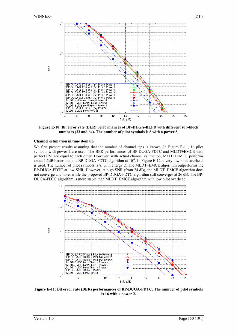
WINNER+ D1.9
Version: 1.0 Page 150 (191)
Figure E-10: Bit error rate (BER) performances of BP-DUGA-BLFD with different sub-block numbers (32 and 64). The number of pilot symbols is 8 with a power 8.
Channel estimation in time domain We first present results assuming that the number of channel taps is known. In 371HFigure E-11, 16 pilot symbols with power 2 are used. The BER performances of BP-DUGA-FDTC and MLDT+EMCE with perfect CSI are equal to each other. However, with actual channel estimation, MLDT+EMCE performs about 1.5dB better than the BP-DUGA-FDTC algorithm at 10-4. In 372HFigure E-12, a very low pilot overhead is used. The number of pilot symbols is 8, with energy 2. The MLDT+EMCE algorithm outperforms the BP-DUGA-FDTC at low SNR. However, at high SNR (from 24 dB), the MLDT+EMCE algorithm does not converge anymore, while the proposed BP-DUGA-FDTC algorithm still converges at 26 dB. The BP-DUGA-FDTC algorithm is more stable than MLDT+EMCE algorithm with low pilot overhead.
Figure E-11: Bit error rate (BER) performances of BP-DUGA-FDTC. The number of pilot symbols is 16 with a power 2.

WINNER+ D1.9
Version: 1.0 Page 151 (191)
Figure E-12: Bit error rate (BER) performances of BP-DUGA-FDTC. The number of pilot symbols is 8 with a power 2.
We now present results assuming that the actual number of channel taps is unknown. In the algorithm, the number of channel taps is assumed to be equal to the CP length. We choose a CP length equal to 18 which is longer than the ISI channel length. In 373HFigure E-13, we use 64 pilot symbols with a power 10. The pilot overhead is 25% which is a high pilot overhead. The BER performances of BP-DUGA-FDTC and MLDT with perfect CSI are almost equal to each other. With channel estimation, the BER performance of the BP-DUGA-FDTC algorithm is worse than that of the MLDT+EMCE algorithm. The BP-DUGA-FDTC does not bring any improvement at the second iteration. In 374HFigure E-14, 64 pilot symbols are used, with a power 1. The pilot overhead is 6.1%. At low SNR, the MLDT+EMCE algorithm outperforms the proposed BP-DUGA-FDTC algorithm. At high SNR (from 20 dB), the MLDT+EMCE algorithm does not converge anymore, while the BP-DUGA-FDTC still converges. At 10-4 BER, we obtain a gain of about 3dB, which will increase with decreasing BER. Therefore, in typical rural area channel, the proposed BP-DUGA-FDTC achieves almost the same performance as MLDT+EMCE algorithm with perfect CSI. With low pilot overhead, the BP-DUGA-FDTC algorithm always converges, whereas the MLDT+EMCE algorithm does not converge anymore with high SNR. Thus, the proposed BP-DUGA-FDTC algorithm is more stable. However, such a low pilot overhead might not be preferable, because it results in a strong performance degradation compared to perfect-CSI performance.

WINNER+ D1.9
Version: 1.0 Page 152 (191)
Figure E-13: Bit error rate (BER) performances of BP-DUGA-FDTC and MLDT+EMCE. The number of pilot symbols is 64 with a power 10.
Figure E-14: Bit error rate (BER) performances of BP-DUGA-FDTC and MLDT+EMCE. The number of pilot symbols is 64 with a power 1.
E.2.6 Conclusion Joint channel estimation and decoding in iterative receivers was developed by using factor graphs with Gaussian approximation. For a coded OFDM system, we tested two factor graphs with different structures: BP-DUGA-BLFD and BP-DUGA-FDTC. The BP-DUGA-BLFD implements channel estimation and detection in frequency domain and the factor graph structure is similar to a block fading channel in a single-carrier system. The BP-DUGA-FDTC estimates the channel in time domain and performs detection in frequency domain. Simulation results show that the very low-complexity BP-DUGA-BLFD is not as good as the traditional MLDT+EMCE algorithm. The BP-DUGA-FDTC outperforms the MLDT+EMCE algorithm with low pilot overhead for low BER, when the

WINNER+ D1.9
Version: 1.0 Page 153 (191)
MLDT+EMCE algorithm does not converge anymore. Thus, the BP-DUGA-FDTC is a more stable and less complex algorithm for OFDM systems. However, the low pilot overhead case is not a typical case in a practical system. Thus, the applicability of BP-DUGA for OFDM remains questionable, compared to an approach with EM channel estimation. The BP-DUGA algorithm can be extended to MIMO-OFDM by extending the ISI principles of D1.7 to inter-layer interference and combining it with BP-DUGA-BLFD or BP-DUGA-FDTC.
E.3 Synchronized FDD Downlink Transmission in Cellular OFDMA: Interference-Aware Scheduling as a Key for Spectrally Efficient Transmission
E.3.1 Introduction Transmission with multiple antennas both at the transmitting and receiving ends of a wireless link has become increasingly mature in recent years. From theory, the fundamental capacity gain in the MIMO radio link, being proportional to the minimum of the number of transmit and receive antennas, is well understood for an isolated point-to-point link. A fundamental trade-off between different transmission modes has been pointed out in [ZT03], which are SMUX and SDIV, revealing that the mode maximizing the capacity depends on the actual channel state. This fact motivated the development of an adaptive transmission system, selecting the transmission mode depending on the actual channel quality in order to improve the error rate performance for fixed data rate transmission [HP05] or to increase the spectral efficiency [CLH04]. To enable ubiquitous broadband wireless access, MIMO transmission must be made robust against multi-cell interference. However, it has not been fully evident yet how the potential capacity gains of MIMO can be realized under these conditions. In fact, early results obtained for a small set of linear transceiver setups, indicate only small gains for SMUX over SDIV systems [CDG00]. The achievable spectral efficiency may be enhanced by enabling MU-MIMO into system design and thus turning the focus to multi-user links [GKHCS07]. However, BSs would require coherent channel state information to optimally serve their users in MU-MIMO, which is difficult to obtain in FDD systems, as a high rate feedback link would be required. Further, fair resource assignment is mandatory in cellular networks in order to guarantee radio access for all users. The multi-path structure of signal and interference channels may be used beneficially in this interference-aware scheduling process. Supplemental to the time-domain scheduling already used in todays radio systems, groups of frequency resources may be assigned to the users according to frequency-selective SINR conditions. In this case users may beneficially be assigned to their best resources. In a previous report [WIN+D14 section 2.1.2] we described a system concept, which is well aligned with the one described here. These new results provide deeper insights in the key relations for a spectrally efficient transmission and highlight the main requirements. For a more detailed description refer to the work described in [JJJ+09], [TWSJ09].
Applicability Comment Duplexing mode FDD/TDD FDD Link (UL/DL) DL Usage and deployment and usage scenario (hot spot, micro-cellular, macro-cellular)
Wide area
Topology Conventional cellular with multiple cells
Support for relays Not considered CSIT requirements Feedback of precoder indexes Field of main contribution Performance evaluation of interference
aware acheduling Targeting a practical solution, we consider to use fixed beams for transmission as depicted in 375HFigure E-15. Terminals are assumed to report their preferred pre-coding indices in combination with corresponding post-equalization SINR via a low-rate feedback channel. For the equalization at the UT, comprehensive channel knowledge of the radio system is required, which may be obtained by multi-cell channel estimation based on pilot symbols. Therefore downlink transmission has to be synchronized

WINNER+ D1.9
Version: 1.0 Page 154 (191)
[JWS+08]. With this approach we demonstrate substantial capacity gains for MIMO systems in multi-cell environments, similar to those known for point-to-point links. We further indicate potential performance gains under the influence of imperfect channel estimation in systems with non-synchronized and synchronized BSs.
Figure E-15: System concept assuming multiple antennas at the base station for the purpose of unitary fixed DFT-based pre-coded beamforming. SINR feedback is provided by the terminal for
possible transmission modes using a narrow band feedback channel.
E.3.2 System Model The downlink MIMO-OFDM transmission system for an isolated sector with NT transmit and NR receive antennas per UT is described on each subcarrier by
,= nHCxy + where H is the NR x NT channel matrix and C the unitary NT x NT pre-coding matrix; x denotes the NT x 1vector of transmit symbols; y and n denote the NR x 1vectors of the received signals and of the AWGN samples, respectively, with covariance EnnH = σ2I. The evaluation process is briefly sketched as follows: Assume that all BSs provide Ω fixed unitary beam sets Cω, ω= 1,…,Ω. For the case of NT =2 and Ω=2 the beam sets based on the DFT-matrix are given as
⎥⎦
⎤⎢⎣
⎡−⎥
⎦
⎤⎢⎣
⎡− 11
112
1=11
21= 21 CC
ii , In general, each beam set contains NT fixed pre-coding vectors (beams) bω,u with u = 1,…, NT. Each BS i independently selects one of these sets. In the following we denote bi,u as the u-th pre-coding vector used by BS i. The received downlink signal ym at the UT m in the cellular environment is given by
444444 3444444 214444 34444 21
4434421
ui
jljlml
TN
jlil
ui
jijimi
TN
juj
ui
ui
uimi
m xxx
,
,,1=
,
,,1=
,
,
,=
zζ
h
nbHbHbHy +++ ∑∑∑∀≠≠
The desired data stream xi,u transmitted on the u-th beam from the i-th sector is distorted by the intra-sector and inter-sector interference aggregated in ξi,u and zi,u, respectively. Each BS may select a limited number Qi<NT of active beams in the chosen set to serve the users simultaneously. Thus, the transmit power per beam is uniformly distributed over all non-zero transmit symbols xi,j with pi/Qi , where
2,1=
||E= jiTN
ji xp ∑ is the total available power for BS i. If only one beam is active, i.e. Qi=1, we name it single-stream mode, while for Qi>1, we refer to it as multi-stream mode. In case of multi-stream transmission we can distinguish between a transmission to a single-user, i.e. SU-MIMO, or a transmission in order to serve multiple users, i.e. MU-MIMO. To enable interference-aware scheduling in a cellular system, CCI has to

WINNER+ D1.9
Version: 1.0 Page 155 (191)
be predictable. This can be achieved by limiting the available beams to a single set, i.e. Ω=1, yielding a static pre-coding.
E.3.3 Linear Receive Filters and Imperfect Channel Estimation
Assuming a linear equalizer uw , which is required to extract the useful signal from my , yields a post-
equalization SINR at the UT for stream uix , given by
,=SINR ,,
uuHu
uH
uiuiHu
iu pwZw
whhw
where uZ is the covariance matrix of the interfering signals aggregated in ui ,ζ and ui ,z , i.e.
( )( )[ ]Huiuiuiuiu ,,,,E= zζzζZ ++ , with [.]E being the expectation operator.
For IRC [W84], the interference-aware MMSE receiver is used:
i
uiyyiu Q
p ,1
MMSE =hR
w−
where yyR denotes the covariance matrix of the received signal my , i.e.
( )[ ] Huiuiu
Hmmyy ,,=E= hhZyyR +
According to [TSZJ07], the MMSE receiver yields a post-equalization SINR
uiuH
ui
i
iu Q
p,
1,
MMSE =SINR hZh −
Based on this SINR, the achievable spectral efficiency is evaluated in a downlink OFDMA multi-cellular simulation environment. For reference purpose, we compare these results with the performance achievable by using a MRC receiver
uiu ,MRC = hw
yielding a post-equalization SINR
uii
Hui
uiH
ui
i
i
uQp
,,
2
,,MRC =SINR
hZh
hh
While for theoretical investigations full CSIR may be assumed, the challenge for practical systems is the robustness against channel estimation errors. In [TSWJ08], IRC was shown to be highly sensitive to estimation errors, since the spatial structure of the system's covariance matrix is utilized for equalization. In the following we assume quasi-static channel conditions over the observation interval. According to the analysis carried out in [WIN+D14 Appendix A.1] we extend the evaluation process to cover synchronized as well as non-synchronized cellular downlink transmssion. Non-synchronized BS, i.e. BS are not synchronized to each other with respect to carrier frequencies and frame start. Therefore, we introduce channel estimation errors according to
uiuiui ,,, =~
δ+hh .
ui,
~h denotes the estimate of variable ui,h , and ui ,δ denotes the zero-mean Gaussian distributed error with variance μ , being the normalized MSE for channel estimation. For SINR estimation, we consider
knowledge on frequency-flat and frequency-selective iid interference powers 2IFσ according to Eq. (E.7)
and Eq. (E.8), respectively. Further, we consider the case of full frequency-selective covariance

WINNER+ D1.9
Version: 1.0 Page 156 (191)
knowledge Eq. (E.9) based on received data signals my . In the following, f and n denote the discrete frequency index and the discrete time index, respectively.
Frequency-flat iid interference power 2IFσ
⎟⎟⎟
⎠
⎞
⎜⎜⎜
⎝
⎛+
⎥⎥
⎦
⎤
⎢⎢
⎣
⎡−⎟⎟
⎠
⎞⎜⎜⎝
⎛∑∀
22,
2,
,
|)(~
||)(|E=~
σff uijljl
fu hhIZ
(E.7)
Frequency-selective iid interference power 2IFσ
⎟⎟⎟
⎠
⎞
⎜⎜⎜
⎝
⎛+−⎟⎟
⎠
⎞⎜⎜⎝
⎛∑∀
22,
2,
,|)(
~||)(|=)(
~σfff uijl
jlu hhIZ
(E.8)
Frequency-selective covariance uZ
[ ] H,,
H )(~
)(~
),(),(E=)(~
ffnfnff uiuimm
nu hhyyZ − (E.9)
Synchronized BS, using multi-cell channel estimation based on virtual pilot sequences [TSSJ08], [WIN+D14 Appendix B.1]. These sequences are block-orthogonal and are defined over time-domain. For channel estimation, the receiver is based on a simple correlator. For simplicity we drop the frequency index f .
Correlation approach
)()(1=~
,
1
0=, nnc
Nm
ui
N
nui yh ∗
−
∑
(E.10)
H
uiuijljljl
u ,,
H
,,,
~~~~=
~hhhhZ −∑
∀ (E.11)
E.3.4 Resource Allocation and Fair User Selection Criteria Resource allocation and selection of the proper spatial transmission mode (i.e. single-stream or multi-stream) is carried out by a score-based scheduling process developed in [STJH07], which is briefly described as follows: In a first step, the user terminals evaluate the current channel conditions per RB in terms of their achievable SINR conditions. By using SINR expression from Section 376HE.3.3 and a suitable SINR-to-rate mapping function, they can determine for each transmission mode the achievable rate per supported beam. This information is conveyed to the base station, where a score-based resource scheduling algorithm is performed: To enable direct comparison of the single per-beam rates from different spatial modes, the single-stream rates are weighted by a so-called penalty factor, which accounts for the higher power allocated to the single-stream beam compared to multi-stream mode. In particular, if Q is the number of simultaneously active streams in multi-stream mode, the penalty factor is chosen as
1−Q . For each user, the (weighted) per-beam rates from all modes over all RB are ranked by their quality, and corresponding scores are assigned. Mode selection and resource assignment is then done for each RB individually: Firstly, each beam available per transmission mode is assigned to the user providing minimum score for that beam. Thereafter, the mode is selected which comprises the minimum overall user score.
The objective of this score-based resource allocation process is to assign each user his best resources, and the decision on the spatial mode is taken under the premise of achieving a high throughput for each user. Clearly, the process is of heuristic nature, and hence the global scheduling target of assigning each user an equal amount of resources is achieved on average only or if the number of available resources tends to infinity. However, its convenient property for practical applications is its flexible utilization, as the set of resources can be defined over arbitrary dimensions (time/frequency/space). Thus, fairness can be established on a small time scale, e.g. even for the scheduling of resources contained within a single OFDM symbol.

WINNER+ D1.9
Version: 1.0 Page 157 (191)
An illustration of the performance achievable by the score-based scheduler is given in 377HFigure E-16. It depicts the histogram of normalized achievable user rates in the rate region plane for two users, which may be scheduled in each RB. In particular, we assume two spatial layers to be available in each RB (i.e.NT=2 and NR=2), allowing two users to be served simultaneously in MU-MIMO mode. The rate allocated to each of these two users is normalized to the rate it would achieve if the RB was assigned exclusively to it. 378HFigure E-16 (a) shows the distribution of normalized rates if the total set of users to select from is limited to 2=K , while 379HFigure E-16 (b) refers to the case 20=K . From both figures, it is clearly seen that the achievable rates lie beyond the TDMA rate region (indicated by the dashed red line in the rate region plane). For increasing number of users K , the histograms is more and more concentrated in the upper right corner of the rate region. This illustration indicates that the heuristic score-based scheduling approach significantly outperforms TDMA scheduling and conveniently achieves high user rates by properly utilizing the MU-MIMO mode.
K=2 users K=20 users
Figure E-16: Rate allocation across two data streams.
E.3.5 Performance Evaluation We investigate the performance in a triple-sectored hexagonal cellular network with 19 BS in total, i.e. a center cell surrounded by two tiers of interfering cells. Simulation parameters are given in [TWSJ09]. Initial results are based under the assumption of full and perfect CSIR. The SCME with urban macro scenario parameters is used [3GPP-TR25996], yielding an equivalent user's geometry as reported in [HVKS03]. The UTs are always served by the BSs whose signal is received with highest average power over the entire frequency band. For capacity evaluation, only UTs being placed inside of the center cell will be considered. In this way, BS signals transmitted from 1st and 2nd tier model the inter-cell interference [TSZJ07]. Performance is evaluated for both the sum throughput in a sector and the throughput for individual users. Both values are normalized to the signal bandwidth, yielding a sector's overall spectral efficiency and normalized user throughput, respectively. The achievable rates are determined from the SINR using a quantized rate mapping function [WIN2D223], representing achievable rates in a practical system. From these results, CDF plots according to Figure E-17 are obtained. Case 1: All BSs provide 1=Ω fixed unitary beam set. With respect to the SISO reference case, our results in 380HFigure E-18 (solid lines) indicate a capacity increase of the median sector's spectral efficiency by a factor of 1.95=α , 2.88=α and 3.43=α for the MIMO 22× ( RT NN × ), 42× and
44× system. We can observe only small additional capacity gains for systems with RT NN >
compared to radio system with RT NN = . This is mainly caused by the constraint of DFT-based pre-coding, where the total transmit power is distributed evenly over all transmit antennas. In contrast, the system with RT NN < benefits from advanced capabilities for interference suppression, as well as higher receive diversity. This enables the system to achieve larger scaling factors, e.g. 2.88=α for MIMO 42× . The 5-percentile of the normalized user throughput, which may serve as a measure to represent the throughput of cell-edge users, shows similar scaling. Case 2: All BSs provide 1>Ω fixed unitary beam sets. 381HFigure E-18 (dashed lines) further indicates the potential capacity gains for allowing the users to choose from multiple beam sets 2,4, ∈ωωB . On the one hand, the system may profit from additional beamforming gains yielding a capacity increase of
2.11=α for MIMO 22× with 2=Ω beam . However, note that in case of non-unitary precoding
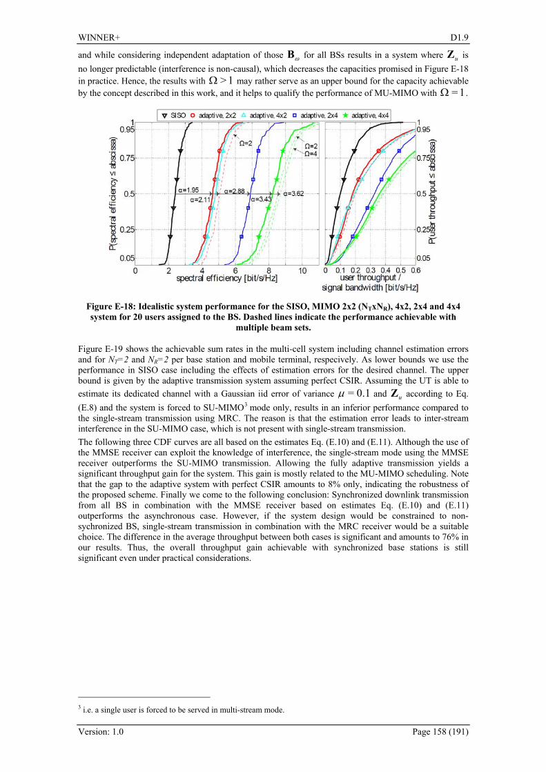
WINNER+ D1.9
Version: 1.0 Page 158 (191)
and while considering independent adaptation of those ωB for all BSs results in a system where uZ is no longer predictable (interference is non-causal), which decreases the capacities promised in 382HFigure E-18 in practice. Hence, the results with 1>Ω may rather serve as an upper bound for the capacity achievable by the concept described in this work, and it helps to qualify the performance of MU-MIMO with 1=Ω .
Figure E-18: Idealistic system performance for the SISO, MIMO 2x2 (NTxNR), 4x2, 2x4 and 4x4 system for 20 users assigned to the BS. Dashed lines indicate the performance achievable with
multiple beam sets.
383HFigure E-19 shows the achievable sum rates in the multi-cell system including channel estimation errors and for NT=2 and NR=2 per base station and mobile terminal, respecively. As lower bounds we use the performance in SISO case including the effects of estimation errors for the desired channel. The upper bound is given by the adaptive transmission system assuming perfect CSIR. Assuming the UT is able to estimate its dedicated channel with a Gaussian iid error of variance 0.1=μ and uZ according to Eq. (E.8) and the system is forced to SU-MIMO2F
3 mode only, results in an inferior performance compared to the single-stream transmission using MRC. The reason is that the estimation error leads to inter-stream interference in the SU-MIMO case, which is not present with single-stream transmission. The following three CDF curves are all based on the estimates Eq. (E.10) and (E.11). Although the use of the MMSE receiver can exploit the knowledge of interference, the single-stream mode using the MMSE receiver outperforms the SU-MIMO transmission. Allowing the fully adaptive transmission yields a significant throughput gain for the system. This gain is mostly related to the MU-MIMO scheduling. Note that the gap to the adaptive system with perfect CSIR amounts to 8% only, indicating the robustness of the proposed scheme. Finally we come to the following conclusion: Synchronized downlink transmission from all BS in combination with the MMSE receiver based on estimates Eq. (E.10) and (E.11) outperforms the asynchronous case. However, if the system design would be constrained to non-sychronized BS, single-stream transmission in combination with the MRC receiver would be a suitable choice. The difference in the average throughput between both cases is significant and amounts to 76% in our results. Thus, the overall throughput gain achievable with synchronized base stations is still significant even under practical considerations.
3 i.e. a single user is forced to be served in multi-stream mode.

WINNER+ D1.9
Version: 1.0 Page 159 (191)
Figure E-19: Spectral efficiency of various transmission schemes including estimation errors.
E.3.6 Conclusion This section evaluates the gains from using interference-aware, frequency-selective MU-MIMO scheduling in a cellular network with synchronized BSs. Terminals are assumed to be able to estimate their dedicated and interfering channel coefficients. With the suggested scheduling approach, we can conclude with two important observations: Efficient MU-MIMO transmission can be achieved by using fixed DFT-based unitary pre-coding, i.e. without the requirement of full CSIT. Further, proper application of the MU-MIMO mode enables to conveniently serve even users in the multi-stream mode who experience relatively poor SNR conditions. Thus, the MU-MIMO mode establishes a win/win situation for low- and high-rate users competing for a resource: Low-rate user can be served without blocking a given resource for any high-rate users, who can support a rate on any of the available beams. We further studied the suggested concept in an interference-limited environment and observed that knowledge of the interference channels yields a more precise estimation of the achievable SINR compared to the traditional approach, where interference is assumed to be white. The work described in [STW+09], [JJJ+09] confirmed the significantly increased probability to select the multi-stream mode also for realistic propagation conditions. Those results were directly obtained from the Berlin LTE-Advanced testbed, which represents a typical urban macro deployment.
E.4 CSI signaling for CoMP in TDD mode
E.4.1 Introduction Efficient transmit precoding or beamforming requires complex spatial channel state information at the transmitter (CSIT). Multi-user precoding, i.e., simultaneous precoding for multiple users, requires centralized CSIT of all the terminals. In the time division duplex (TDD) mode, CSIT for the BS is provided by means of uplink CSI sounding pilot signals. CSIT can be used as a reference for scheduling as well. However, antenna-specific uplink pilot streams cause an extensive overhead that restricts the size of the practical user group and the terminal antenna setup that can be handled within the same time-frequency slot. Furthermore, if we wish to employ advanced multicell beam coordination or CoMP, the BSs need to obtain CSI towards the UTs served by the neighbouring base stations as well. Thus, the overhead problem is escalated further, as common orthogonal sounding pilot resources need to be allocated within the area of multiple cells. Here, a multicell CSI sounding concept for terminals employing arbitrarily many antennas is presented. The objective is to support different multicell beam coordination algorithms with reasonable pilot overhead and with minimal backhaul between BSs. The concept combines the ideas of CSI sounding overhead reduction [WIN+D17 Section 2.3] and that of beamformed busy signaling [WIN+D15 Section 2.4].

WINNER+ D1.9
Version: 1.0 Page 160 (191)
Applicability Comment Duplexing mode FDD/TDD TDD Link (UL/DL) Data for DL, signaling in UL Usage and deployment and usage scenario (hot spot, micro-cellular, macro-cellular)
Local area
Topology Conventional cellular with multiple cells
Support for relays Not considered CSIT requirements Local CSI in UTs by DL obtained by
common pilot, CSIT in BS obtained by UL sounding
Field of main contribution Pilot signalling: UL CSI sounding for multi-cell systems
E.4.2 Description The CSI sounding overhead reduction concept [WIN+D17 Section 2.3] is based on letting a terminal that employs Nk antennas form Jk uplink pilot beams, where Jk < Nk, by transmit precoding instead of transmitting Nk antenna-specific pilots. The sounding beams are formed based on the knowledge of the user-specific MIMO channels, obtained via the downlink common pilot signal. This way part of the signaling overhead is moved to the downlink, which is more resource efficient. On the other hand, by the beamformed busy signaling concept [WIN+D15 Section 2.4], a UT informs the neighbouring BSs of its composite channel – consisting of the MIMO channel and the active UT receive filter – so that each BS knows in which direction of the signal space it should avoid from generating interference. Furthermore, the received signal strength of the busy signal indicates the distance of the UT. The busy signaling has formerly been proposed to be transmitted in dedicated time slots. The busy signal essentially renders the CSI exchange via backhaul between the BSs unnecessary. In this concept, the UT decomposes its spatial signal space into busy, sounding, and weak subspaces. For example, employ SVD as
[ ] [ ]HWeakSoundBusy
Weak
Sound
Busy
WeakSoundBusy2/1 VVV
Σ000Σ000Σ
UUUHR⎥⎥⎥
⎦
⎤
⎢⎢⎢
⎣
⎡=− ,
where H is the M x Nk MIMO channel between the BS and the UT, and R is the inter-cell interference and noise covariance matrix seen by the UT. The precoding matrix for the uplink pilot becomes then UPilot = R-1/2[UBusy USound] that provides the channel sounding signal to the own BS. On the other hand the beams in UBusy indicate the signal subspace that is already busy and allocated with DL data streams. The size of UPilot is Nk x Jk, where Jk is a constant defined either by the BS or the UT itself. What remains to be signaled to the neighbour BSs is how many of the pilots are busy pilots. This number can be conveyed either via backhaul between BSs or by inband signaling by the UT. The weak eigenmodes are unlikely to be allocated with data streams, and thus neglecting them is justified in order to reduce overhead. In the previous example, all signaling was based on user-specific eigenbeams. This approach is best suitable when transmission based on multi-user eigenmodes is employed in the network. Alternatively, the busy beams can be constructed based on orthogonalized receive filters so that the BS can have more freedom in the precoder selection. The receive filters are optimal for the purpose of multicell interference avoidance. In this case, the rest of the sounding precoders may be selected such that the total pilot matrix spans the strongest possible signal subspace of the UT.
E.4.3 Expected benefits The proposed signaling concept accommodates advanced coordinated spatial processing by different CoMP algorithms in TDD mode. It also allows advanced terminals to benefit from employing arbitrary numbers of antenna elements without increasing the pilot overhead, or without affecting standard specifications.
WINNER+ D1.9
Version: 1.0 Page 161 (191)
E.4.4 Requirements on signaling The proposed concept requires symbol synchronism between the BSs, and multicell pilot sequence allocation. This way, all the BSs of the coordination cluster can distinguish the pilot responses from all the UTs without inter-cell interference. The presence of a DL common pilot is also required so that each UT can characterize its MIMO channel towards its own BS.
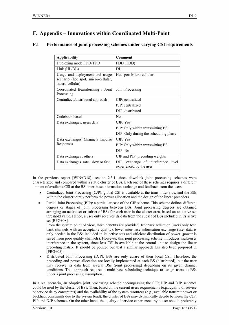
WINNER+ D1.9
Version: 1.0 Page 162 (191)
F. Appendix – Innovations within Coordinated Multi-Point
F.1 Performance of joint processing schemes under varying CSI requirements
Applicability Comment Duplexing mode FDD/TDD FDD (TDD) Link (UL/DL) DL Usage and deployment and usage scenario (hot spot, micro-cellular, macro-cellular)
Hot spot/ Micro-cellular
Coordinated Beamforming / Joint Processing
Joint Processing
Centralized/distributed approach CJP: centralized PJP: centralized DJP: distributed
Codebook based No Data exchanges: users data CJP: Yes
PJP: Only within transmitting BS DJP: Only during the scheduling phase
Data exchanges: Channels Impulse Responses
CJP: Yes PJP: Only within transmitting BS DJP: No
Data exchanges : others Data exchanges rate : slow or fast
CJP and PJP: precoding weights DJP: exchange of interference level experienced by the user
In the previous report [WIN+D18], section 2.3.1, three downlink joint processing schemes were characterized and compared within a static cluster of BSs. Each one of these schemes requires a different amount of available CSI at the BS, inter-base information exchange and feedback from the users:
• Centralized Joint Processing (CJP): global CSI is available at the transmitter side, and the BSs within the cluster jointly perform the power allocation and the design of the linear precoders.
• Partial Joint Processing (PJP): a particular case of the CJP scheme. This scheme defines different degrees or stages of joint processing between BSs. Joint processing degrees are obtained arranging an active set or subset of BSs for each user in the cluster area, based on an active set threshold value. Hence, a user only receives its data from the subset of BSs included in its active set [BPG+08]. From the system point of view, three benefits are provided: feedback reduction (users only feed back channels with an acceptable quality), lower inter-base information exchange (user data is only needed in the BSs included in its active set) and efficient distribution of power (power is saved from poor quality channels). However, this joint processing scheme introduces multi-user interference in the system, since less CSI is available at the central unit to design the linear precoding matrix. It should be pointed out that a similar approach has also been proposed in [PBG+08].
• Distributed Joint Processing (DJP): BSs are only aware of their local CSI. Therefore, the precoding and power allocation are locally implemented at each BS (distributed), but the user may receive its data from several BSs (joint processing) depending on its given channel conditions. This approach requires a multi-base scheduling technique to assign users to BSs under a joint processing assumption.
In a real scenario, an adaptive joint processing scheme encompassing the CJP, PJP and DJP schemes could be used by the cluster of BSs. Then, based on the current users requirements (e.g., quality of service or service delay constraints) and the availability of the system resources (e.g., available transmit power or backhaul constraints due to the system load), the cluster of BSs may dynamically decide between the CJP, PJP and DJP schemes. On the other hand, the quality of service experienced by a user should preferably

WINNER+ D1.9
Version: 1.0 Page 163 (191)
not be location dependent, that is, the joint processing scheme should provide a uniform performance over the cluster area. Thus, users location and mobility are other factors that should influence this decision. In this section, new performance results of the CJP, PJP and DJP schemes are presented, in addition to the ones included in [WIN+D18], Appendix A.4. Simulations are carried out following the same approach as in [WIN+D18], section A.4.4, over a static cluster of 3K = BSs, each one equipped with
3tN = antennas, where M single-antenna users are using a particular orthogonal dimension (see 384HFigure F-1). In this case, the probability of outage area, the average sum-rate per cell and a backhaul-load weighted average sum-rate per cell are the metrics considered for each one of the joint processing schemes.
Figure F-1: The cluster area under consideration is the shadowed area close to the cell-edge of each cell.
385HFigure F-2 compares the average sum-rate per cell achieved by the different schemes for a 5% probability of outage area [YH07] in an interference-limited scenario. A 5% probability of outage area metric indicates that the average sum-rate per cell is below a given value only in a 5% of the locations in the cluster area. “PJP-10dB”, “PJP-20dB” and “PJP-40dB” plots stand for the results of the PJP scheme when active set threshold values of 10, 20 or 40 dB are simulated, respectively. For comparison purposes, results for the conventional single-base station transmission scheme, “1BS”, are also included as a base-line. Results labeled with “2BSs” are obtained when each user receives its data from 2 BSs. This is a particular case of the PJP. From 386HFigure F-2, it can be seen that the CJP scheme clearly outperforms the remaining schemes, but this gain comes at the cost of a higher requirement of backhaul exchange and feedback from the users. The PJP scheme defines a trade-off between the required amount of backhaul exchange and feedback from the users and the achieved average sum-rate per cell, that is, its performance improves as the joint processing degree between BSs or the threshold value increases. Therefore, the threshold value arises as a key parameter in order to dynamically adapt in time the amount of backhaul exchange and feedback from the users. On the other hand, both the performance of the CJP and PJP schemes (including the “2BSs” case) decreases as the system becomes spatially overloaded. This is due to the design of the linear precoding as a ZF beamformer, and the suboptimal power allocation performed by the cluster (see [WIN+D18], section A.4.1). The performance of the DJP scheme remains almost constant as the number of users increases, since in this case, the number of users that each BS can serve is spatially constrained to the number of antennas in each BS. Hence, some users may remain without being served.

WINNER+ D1.9
Version: 1.0 Page 164 (191)
Figure F-2: Average sum-rate per cell for a 5% probability of outage area. Results are shown for M= 3, 6, 9 and 12 users and a system SNR of 15 dB.
In 387HFigure F-3, the average sum-rate per cell obtained by the different joint processing schemes is plotted when moving from BS 1 along the dashed line in 388HFigure F-1 In this case, M = 6 users are placed in each position of the grid, which is the value that maximizes the performance of the CJP scheme in 389HFigure F-2. When comparing the curves of the PJP scheme with the “2BSs” scheme results, we can conclude that by allowing a different number of BSs to transmit to each user, depending on the user channel conditions, we can also improve the average sum-rate per cell, since we are increasing the flexibility of our system. Comparing now the results of 390HFigure F-2 for M = 6 users and 391HFigure F-3 it can be seen that the “2BSs” and DJP transmission schemes achieve a better performance with respect to the “PJP-10dB” in terms of the average sum-rate per cell for a given probability of outage area metric. This illustrates that the suitability of a given scheme also depends on the metric under consideration and motivates further research on this direction.
Figure F-3: Average sum-rate per cell versus normalized distance [Distance/R] when moving from BS 1 along the dashed line in 392HFigure F-1. Results are shown for M = 6 users and a system SNR of 15
dB.
In the CJP scheme, the required amount of backhaul exchange and feedback from the users remains fixed regardless of the location of the users in the cluster area. In the case of the DJP scheme, when the M users are placed in a certain location of the grid, they may be served by a number of BSs that ranges from zero (in the case of users being in outage due to the spatial limitation to tN in the design of the beamformers) to K = 3. Notice that the number of BSs serving a user is also position-dependent. 393HTable F-1 shows the
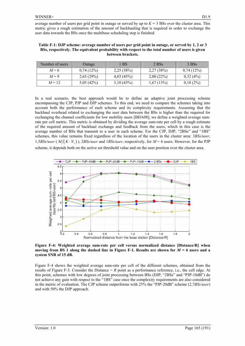
WINNER+ D1.9
Version: 1.0 Page 165 (191)
average number of users per grid point in outage or served by up to K = 3 BSs over the cluster area. This metric gives a rough estimation of the amount of backhauling that is required in order to exchange the user data towards the BSs once the multibase scheduling step is finished.
Table F-1: DJP scheme: average number of users per grid point in outage, or served by 1, 2 or 3 BSs, respectively. The equivalent probability with respect to the total number of users is given
between brackets.
Number of users Outage 1 BS 2 BSs 3 BSs M = 6 0,74 (12%) 2,25 (38%) 2,27 (38%) 0,74 (12%) M = 9 2,65 (29%) 4,03 (45%) 2,00 (22%) 0,32 (4%)
M = 12 5,05 (42%) 5,10 (43%) 1,67 (13%) 0,18 (2%) In a real scenario, the best approach would be to define an adaptive joint processing scheme encompassing the CJP, PJP and DJP schemes. To this end, we need to compare the schemes taking into account both the performance of each scheme and its complexity requirements. Assuming that the backhaul overhead related to exchanging the user data between the BSs is higher than the required for exchanging the channel coefficients for low mobility users [BHA08], we define a weighted average sum-rate per cell metric. This metric is obtained by dividing the average sum-rate per cell by a rough estimate of the required amount of backhaul exchange and feedback from the users, which in this case is the average number of BSs that transmit to a user in each scheme. For the CJP, DJP, “2BSs” and “1BS” schemes, this value remains fixed regardless of the location of the users in the cluster area: 3BSs/user, 1,5BSs/user ( ( )tM K N⋅ ), 2BSs/user and 1BSs/user, respectively, for M = 6 users. However, for the PJP scheme, it depends both on the active set threshold value and on the user position over the cluster area.
Figure F-4: Weighted average sum-rate per cell versus normalized distance [Distance/R] when moving from BS 1 along the dashed line in 394HFigure F-1. Results are shown for M = 6 users and a system SNR of 15 dB. 395HFigure F-4 shows the weighted average sum-rate per cell of the different schemes, obtained from the results of 396HFigure F-3. Consider the Distance = R point as a performance reference, i.e., the cell edge. At this point, schemes with low degrees of joint processing between BSs (DJP, “2BSs” and “PJP-10dB”) do not achieve any gain with respect to the “1BS” case once the complexity requirements are also considered in the metric of evaluation. The CJP scheme outperforms with 25% the “PJP-20dB” scheme (2,7BSs/user) and with 50% the DJP approach.

WINNER+ D1.9
Version: 1.0 Page 166 (191)
F.2 Performance of distributed joint processing with multi-antenna receivers and under scalable CSI feedback
Applicability Comment Duplexing mode FDD/TDD FDD, still valid for TDD Link (UL/DL) DL Usage and deployment and usage scenario (hot spot, micro-cellular, macro-cellular)
Macrocellular
Coordinated Beamforming / Joint Processing
Joint Processing
Centralized/distributed approach Distributed Codebook based Perfect CSI, but may be extend to pre-
agreeed codebooks Data exchanges: users data Users report effective MISO-CSI Data exchanges: Channels Impulse Responses
BS in cluster, exchange their received MISO-CSI and payload data
Data exchanges : others Data exchanges rate : slow or fast
For real-time implementation every 10ms
Higher complexity, growing data rates on the backhaul and the additional overhead are challenges for the application of CoMP techniques, especially in the downlink. Hence, a distributed system architecture has been suggested where BS communicate directly with their vicinity [ZSKJS06], [JTS+08], [PHG09]. This significantly reduces the infrastructural overhead in the system and allows an efficient distributed computation of the pre-coder using localized CSI knowledge. In addition, [BH07], [JTS+08], [ZMSTJS09], [TWH+09] provide several methods to break down the required feedback overhead. To the best of our knowledge, a real-time implementation of distributed CoMP in the cellular downlink is reported for the first time in [JTW+09]. In this appendix we focus on the distributed, active interference mitigation of CoMP transmission in the MIMO OFDMA downlink. We propose a practical unified feedback scheme for the required CSIT. The effective multi-cell channel seen after receiver processing is fed back and distributed within the cluster. Thus, each terminal can be treated as a single-antenna receiver. In particular, each terminal can choose its desired receive strategy independently from other mobile terminals according to its computational capabilities. This allows distributed MIMO pre-processing at each base station belonging to a specific cluster and makes the implementation of downlink CoMP transmission feasible. In this work we consider coherent ZF beamforming in the cluster. Furthermore, we derive a solution to efficiently merge linear receive antenna combining and distributed MIMO signal processing. Thus, terminals can use the spatial diversity gains to maximize their received signal strength by MRC. More advanced receivers can improve the SINR by utilizing interference mitigation techniques such as OC [W84]. The different concepts are evaluated in a cellular scenario, taking realistic multi-cell channel modeling into account. Therefore, we consider a cluster surrounded by non-coordinated BS emanating residual CCI. For reference purposes, we use the well-known MET concept. We extend this approach by using OC in advance to feedback provisioning and show that this improves the system throughput significantly. In particular, the user-specific CSI feedback is then based on a near-optimum receive vector, which inherently considers the dominant eigenmode and the residual CCI.
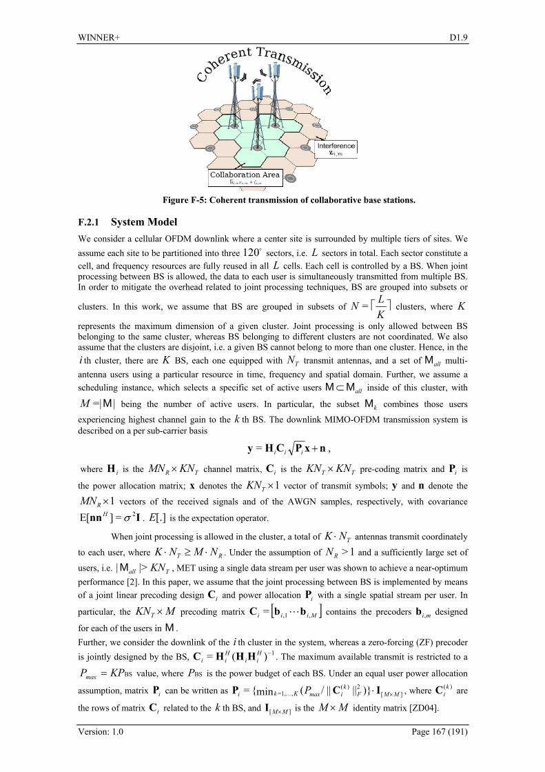
WINNER+ D1.9
Version: 1.0 Page 167 (191)
Figure F-5: Coherent transmission of collaborative base stations.
F.2.1 System Model We consider a cellular OFDM downlink where a center site is surrounded by multiple tiers of sites. We assume each site to be partitioned into three o120 sectors, i.e. L sectors in total. Each sector constitute a cell, and frequency resources are fully reused in all L cells. Each cell is controlled by a BS. When joint processing between BS is allowed, the data to each user is simultaneously transmitted from multiple BS. In order to mitigate the overhead related to joint processing techniques, BS are grouped into subsets or
clusters. In this work, we assume that BS are grouped in subsets of ⎤⎡KLN = clusters, where K
represents the maximum dimension of a given cluster. Joint processing is only allowed between BS belonging to the same cluster, whereas BS belonging to different clusters are not coordinated. We also assume that the clusters are disjoint, i.e. a given BS cannot belong to more than one cluster. Hence, in the i th cluster, there are K BS, each one equipped with TN transmit antennas, and a set of allM multi-antenna users using a particular resource in time, frequency and spatial domain. Further, we assume a scheduling instance, which selects a specific set of active users allMM ⊂ inside of this cluster, with
|=|MM being the number of active users. In particular, the subset kM combines those users
experiencing highest channel gain to the k th BS. The downlink MIMO-OFDM transmission system is described on a per sub-carrier basis
,= nxPCHy +iii
where iH is the TR KNMN × channel matrix, iC is the TT KNKN × pre-coding matrix and iP is
the power allocation matrix; x denotes the 1×TKN vector of transmit symbols; y and n denote the
1×RMN vectors of the received signals and of the AWGN samples, respectively, with covariance
Inn 2=][E σH . [.]E is the expectation operator.
When joint processing is allowed in the cluster, a total of TNK ⋅ antennas transmit coordinately
to each user, where RT NMNK ⋅≥⋅ . Under the assumption of 1>RN and a sufficiently large set of
users, i.e. Tall KN|>|M , MET using a single data stream per user was shown to achieve a near-optimum performance [2]. In this paper, we assume that the joint processing between BS is implemented by means of a joint linear precoding design iC and power allocation iP with a single spatial stream per user. In
particular, the MKNT × precoding matrix [ ]Miii ,,1= bbC L contains the precoders mi ,b designed
for each of the users in M . Further, we consider the downlink of the i th cluster in the system, whereas a zero-forcing (ZF) precoder is jointly designed by the BS, 1)(= −H
iiHii HHHC . The maximum available transmit is restricted to a
BSKPPmax = value, where BSP is the power budget of each BS. Under an equal user power allocation
assumption, matrix iP can be written as ][2)(
,1,= )||||/(min= MMFk
imaxKki P ×⋅ICP K , where )(kiC are
the rows of matrix iC related to the k th BS, and ][ MM ×I is the MM × identity matrix [ZD04].
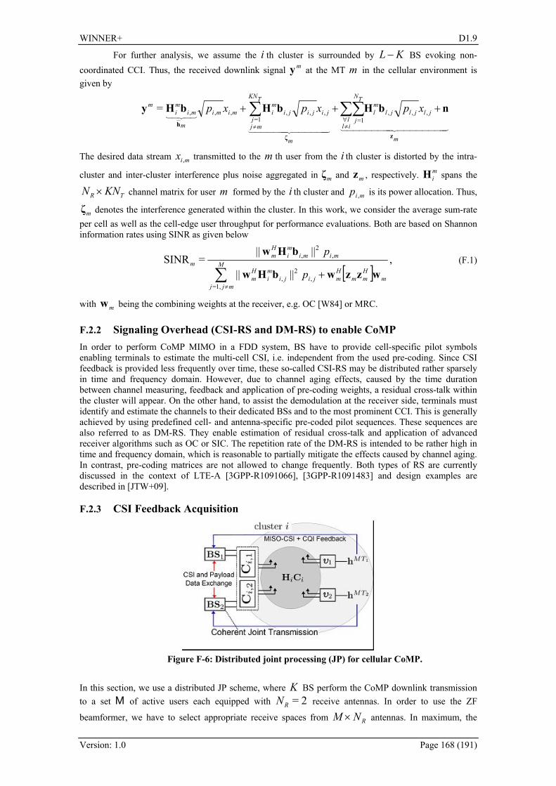
WINNER+ D1.9
Version: 1.0 Page 168 (191)
For further analysis, we assume the i th cluster is surrounded by KL − BS evoking non-coordinated CCI. Thus, the received downlink signal my at the MT m in the cellular environment is given by
44444444 344444444 21444444 3444444 21
43421
m
jljljlml
TN
jlil
m
jijijimi
TKN
jmj
mimi
m
mimi
m xpxpxp
zζ
h
nbHbHbHy +++ ∑∑∑∀≠≠
,,,1=
,,,1=
,,,=
The desired data stream mix , transmitted to the m th user from the i th cluster is distorted by the intra-
cluster and inter-cluster interference plus noise aggregated in mζ and mz , respectively. miH spans the
TR KNN × channel matrix for user m formed by the i th cluster and mip , is its power allocation. Thus,
mζ denotes the interference generated within the cluster. In this work, we consider the average sum-rate per cell as well as the cell-edge user throughput for performance evaluations. Both are based on Shannon information rates using SINR as given below
[ ]
,||||
||||=SINR
,2
,1,=
,2
,
mHmm
Hmjiji
mi
Hm
M
mjj
mimimi
Hm
m
p
p
wzzwbHw
bHw
+∑≠
(F.1)
with mw being the combining weights at the receiver, e.g. OC [W84] or MRC.
F.2.2 Signaling Overhead (CSI-RS and DM-RS) to enable CoMP In order to perform CoMP MIMO in a FDD system, BS have to provide cell-specific pilot symbols enabling terminals to estimate the multi-cell CSI, i.e. independent from the used pre-coding. Since CSI feedback is provided less frequently over time, these so-called CSI-RS may be distributed rather sparsely in time and frequency domain. However, due to channel aging effects, caused by the time duration between channel measuring, feedback and application of pre-coding weights, a residual cross-talk within the cluster will appear. On the other hand, to assist the demodulation at the receiver side, terminals must identify and estimate the channels to their dedicated BSs and to the most prominent CCI. This is generally achieved by using predefined cell- and antenna-specific pre-coded pilot sequences. These sequences are also referred to as DM-RS. They enable estimation of residual cross-talk and application of advanced receiver algorithms such as OC or SIC. The repetition rate of the DM-RS is intended to be rather high in time and frequency domain, which is reasonable to partially mitigate the effects caused by channel aging. In contrast, pre-coding matrices are not allowed to change frequently. Both types of RS are currently discussed in the context of LTE-A [3GPP-R1091066], [3GPP-R1091483] and design examples are described in [JTW+09].
F.2.3 CSI Feedback Acquisition
Figure F-6: Distributed joint processing (JP) for cellular CoMP.
In this section, we use a distributed JP scheme, where K BS perform the CoMP downlink transmission to a set M of active users each equipped with 2=RN receive antennas. In order to use the ZF
beamformer, we have to select appropriate receive spaces from RNM × antennas. In maximum, the
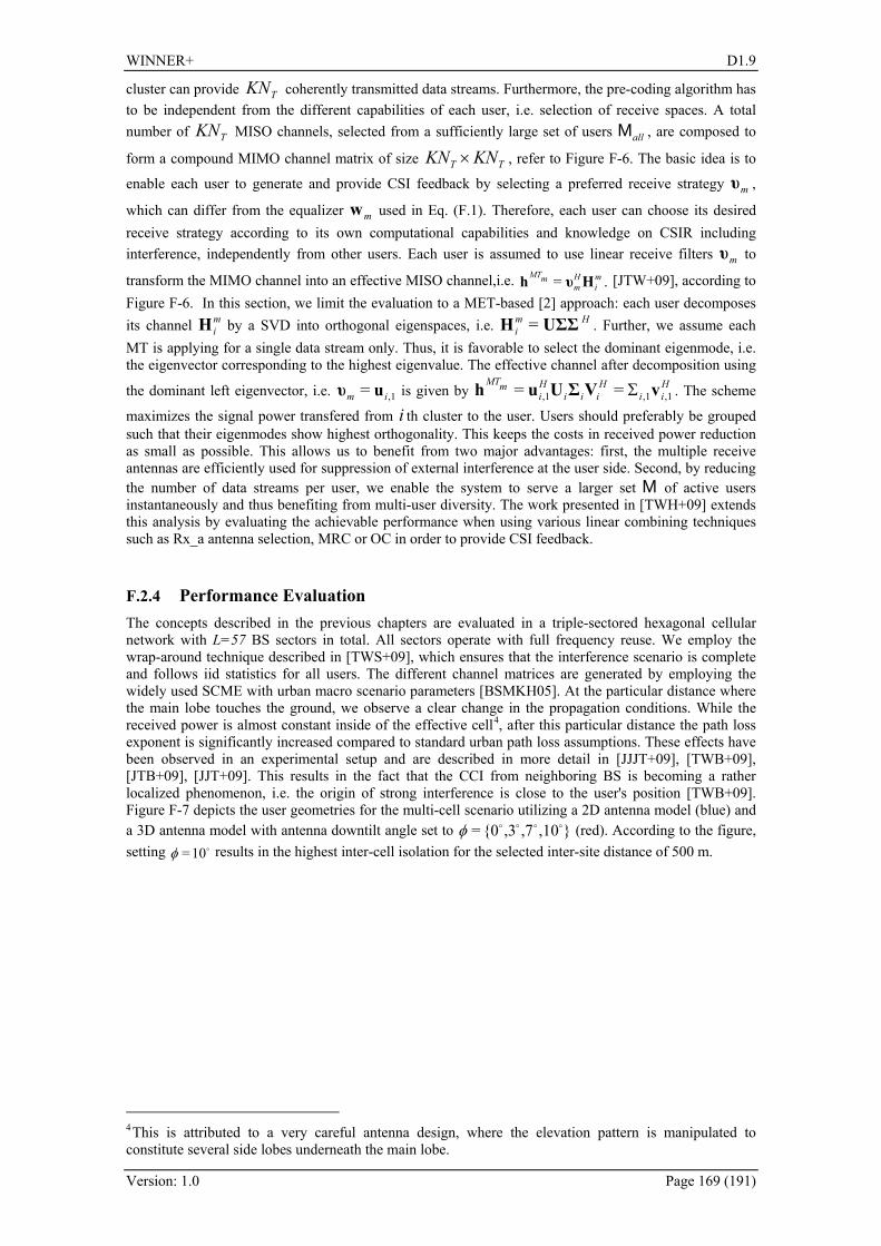
WINNER+ D1.9
Version: 1.0 Page 169 (191)
cluster can provide TKN coherently transmitted data streams. Furthermore, the pre-coding algorithm has to be independent from the different capabilities of each user, i.e. selection of receive spaces. A total number of TKN MISO channels, selected from a sufficiently large set of users allM , are composed to
form a compound MIMO channel matrix of size TT KNKN × , refer to 397HFigure F-6. The basic idea is to
enable each user to generate and provide CSI feedback by selecting a preferred receive strategy mυ ,
which can differ from the equalizer mw used in Eq. (F.1). Therefore, each user can choose its desired receive strategy according to its own computational capabilities and knowledge on CSIR including interference, independently from other users. Each user is assumed to use linear receive filters mυ to
transform the MIMO channel into an effective MISO channel,i.e. .= mi
Hm
mMT Hυh [JTW+09], according to 398HFigure F-6. In this section, we limit the evaluation to a MET-based [2] approach: each user decomposes its channel m
iH by a SVD into orthogonal eigenspaces, i.e. Hmi UΣΣH = . Further, we assume each
MT is applying for a single data stream only. Thus, it is favorable to select the dominant eigenmode, i.e. the eigenvector corresponding to the highest eigenvalue. The effective channel after decomposition using
the dominant left eigenvector, i.e. ,1= im uυ is given by Hii
Hiii
Hi
mMT,1,1,1 == vVΣUuh Σ . The scheme
maximizes the signal power transfered from i th cluster to the user. Users should preferably be grouped such that their eigenmodes show highest orthogonality. This keeps the costs in received power reduction as small as possible. This allows us to benefit from two major advantages: first, the multiple receive antennas are efficiently used for suppression of external interference at the user side. Second, by reducing the number of data streams per user, we enable the system to serve a larger set M of active users instantaneously and thus benefiting from multi-user diversity. The work presented in [TWH+09] extends this analysis by evaluating the achievable performance when using various linear combining techniques such as Rx_a antenna selection, MRC or OC in order to provide CSI feedback.
F.2.4 Performance Evaluation The concepts described in the previous chapters are evaluated in a triple-sectored hexagonal cellular network with L=57 BS sectors in total. All sectors operate with full frequency reuse. We employ the wrap-around technique described in [TWS+09], which ensures that the interference scenario is complete and follows iid statistics for all users. The different channel matrices are generated by employing the widely used SCME with urban macro scenario parameters [BSMKH05]. At the particular distance where the main lobe touches the ground, we observe a clear change in the propagation conditions. While the received power is almost constant inside of the effective cell3F
4, after this particular distance the path loss exponent is significantly increased compared to standard urban path loss assumptions. These effects have been observed in an experimental setup and are described in more detail in [JJJT+09], [TWB+09], [JTB+09], [JJT+09]. This results in the fact that the CCI from neighboring BS is becoming a rather localized phenomenon, i.e. the origin of strong interference is close to the user's position [TWB+09]. 399HFigure F-7 depicts the user geometries for the multi-cell scenario utilizing a 2D antenna model (blue) and a 3D antenna model with antenna downtilt angle set to ,10,7,30= ooooφ (red). According to the figure, setting o10=φ results in the highest inter-cell isolation for the selected inter-site distance of 500 m.
4This is attributed to a very careful antenna design, where the elevation pattern is manipulated to constitute several side lobes underneath the main lobe.
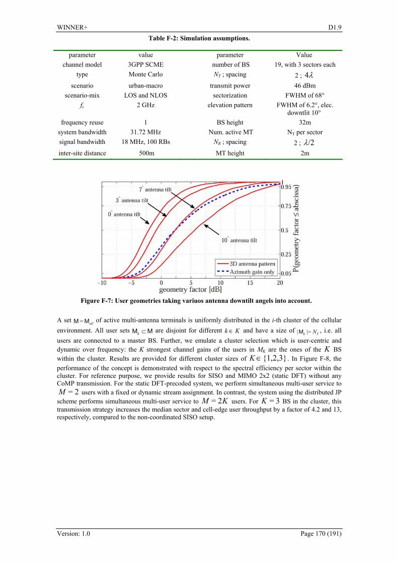
WINNER+ D1.9
Version: 1.0 Page 170 (191)
Table F-2: Simulation assumptions.
parameter value parameter Value channel model 3GPP SCME number of BS 19, with 3 sectors each
type Monte Carlo NT ; spacing 2 ; λ4 scenario urban-macro transmit power 46 dBm
scenario-mix LOS and NLOS sectorization FWHM of 68° fc 2 GHz elevation pattern FWHM of 6.2°, elec.
downtlit 10° frequency reuse 1 BS height 32m
system bandwidth 31.72 MHz Num. active MT NT per sector signal bandwidth 18 MHz, 100 RBs NR ; spacing 2 ; /2λ inter-site distance 500m MT height 2m
Figure F-7: User geometries taking variuos antenna downtilt angels into account.
A set
allMM = of active multi-antenna terminals is uniformly distributed in the i-th cluster of the cellular environment. All user sets MM ⊂k are disjoint for different Kk ∈ and have a size of
Tk N|=|M , i.e. all users are connected to a master BS. Further, we emulate a cluster selection which is user-centric and dynamic over frequency: the K strongest channel gains of the users in MK are the ones of the K BS within the cluster. Results are provided for different cluster sizes of 1,2,3∈K . In 400HFigure F-8, the performance of the concept is demonstrated with respect to the spectral efficiency per sector within the cluster. For reference purpose, we provide results for SISO and MIMO 2x2 (static DFT) without any CoMP transmission. For the static DFT-precoded system, we perform simultaneous multi-user service to
2=M users with a fixed or dynamic stream assignment. In contrast, the system using the distributed JP scheme performs simultaneous multi-user service to KM 2= users. For 3=K BS in the cluster, this transmission strategy increases the median sector and cell-edge user throughput by a factor of 4.2 and 13, respectively, compared to the non-coordinated SISO setup.
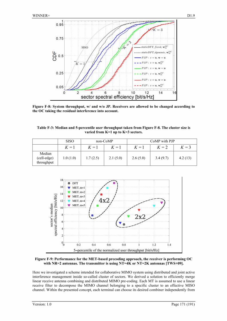
WINNER+ D1.9
Version: 1.0 Page 171 (191)
Figure F-8: System throughput, w/ and w/o JP. Receivers are allowed to be changed according to the OC taking the residual interference into account.
Table F-3: Median and 5-percentile user throughput taken from 401HFigure F-8. The cluster size is varied from K=1 up to K=3 sectors.
SISO non-CoMP CoMP with PJP 1=K 1=K 1=K 1=K 2=K 3=K
Median (cell-edge) throughput
1.0 (1.0) 1.7 (2.5) 2.1 (5.0) 2.6 (5.0) 3.4 (9.7) 4.2 (13)
Figure F-9: Performance for the MET-based precoding approach, the receiver is performing OC with NR=2 antennas. The transmitter is using NT=4K or NT=2K antennas [TWS+09].
Here we investigated a scheme intended for collaborative MIMO system using distributed and joint active interference management inside so-called cluster of sectors. We derived a solution to efficiently merge linear receive antenna combining and distributed MIMO pre-coding. Each MT is assumed to use a linear receive filter to decompose the MIMO channel belonging to a specific cluster to an effective MISO channel. Within the presented concept, each terminal can choose its desired combiner independently from

WINNER+ D1.9
Version: 1.0 Page 172 (191)
other users, following an unified feedback scheme for CoMP systems. The effective MISO channel is fed back and distributed within the collaboration area, where the BS perform a coherent ZF beamforming.
F.2.5 Proof of Feasibility in Experimental Real-Time Setup CoMP can be implemented in two ways: centralized or distributed. In the centralized concept, a central unit (CU) is the genius where all CSI and data are available. The CU pre-computes all waveforms and sends them over a star-like network to the coordinated base stations acting merely as remote radio heads (RRHs). The centralized approach has the drawbacks that a higher backhaul effort is needed since IQ samples of the waveforms are transmitted. Moreover, latency requirements are tight. Waveforms must be irradiated time-aligned on a few µs timescale, i.e. within the cyclic prefix (CP). Since the individual propagation delays must be compensated, this approach is hardly realistic in a real-world network deployment.
Figure F-10: Distributed CoMP downlink transmission (left). Principle of synchoneous data exchange (right).
In the distributed approach, a limited set of base stations (BS) transmit data jointly to multiple terminals in their cells. As a fundamental requirement of the distributed approach, BS exchange data and CSI over the network. Data instead of IQ sample transfer is a lighter burden for the backhaul compared to the centralized approach. Furthermore, the latency constraint is relaxed since waveforms are computed locally at each base station. Data exchange needed therefore can be realized with a latency of a few ms typical for optical transport networks used today. Signal processing can now be distributed, see 402HFigure F-10. Terminals estimate the channel state informtion (CSI) to multiple coherently transmitting base stations and feed back this information to their serving base. Base stations exchange data and CSI and so the become themselves the genious, i.e. each base station has the same CSI and data available and it can compute independently from other base stations the waveforms to be transmitted locally using a local precoder, where inputs are all data streams to be served within the cluster and outputs are the signals to transmitted from the local antennas. The distributively precoded signals combine over the air at the terminals constructively for the desired waveforms and destructively for the interference, see 403HFigure F-10. Clock Synchronization: A first eanbling feature is that physical layer and radio front-ends are tightly synchronized. A precise clock reference can be locally obtained at each base station from the global positioning system. Indoor base stations can be synchronized over the network using standard protocols such as IEEE1588v2 or proprietary solutions like synchronous Ethernet [VHLV09]. From the global reference, all local clock signals needed to synchronize the local oscillators (LOs) as well as frame-, symbol- and sample timing can be derived [JWS+08]. Note that phase noise requirements of local oscillators (LO) are higher compared to base stations used previously. The oscillator phase shall remain the same for all antennas involved in a joint transmission over a period comparable to the feedback delay. Otherwise e.g. for zero-forcing precoding, the precoder is no longer the channel inverse at the time it is applied. Since cooperation clusters may contain multiple sites, the relative LO phase at each site shall be stabilized over several milliseconds. This can be realized by coupling a low phase noise LO to the common GPS reference at each site and sharing it among all sectors. Synchronous Data Exchange: Data flows at the local precoder inputs shall be strictly synchronized, i.e. two base stations involved in a CoMP transmission shall transmit exactly the same data symbol on the same resource element. This is realized as indicated in 404HFigure F-10 right. Data are transmitted in a first hop over the S1 from the advanced gateway (aGW) to the serving base where they are are packed into transport blocks, encoded and mapped on the Resource Block (RB). After the MAC layer, these already mapped data are forwarded in a second hop over the X2 interconnect to all base stations involved in the

WINNER+ D1.9
Version: 1.0 Page 173 (191)
CoMP transmission. Compared to the centralized approach, MAC output data and no IQ samples are exchanged, i.e. the load in the backhaul is reduced. Moreover, retransmissions can be controlled locally. Cell-Specific Pilots: Each base station shall provide cell-specific reference signals from which terminals can estimate the multi-cell CSI. These pilots are sparse in time and frequency to minimize the additonal overhead. One design example for the so-called CSI-reference-signals (CSI-RS) is reported in [JTW+09], and it has been used in the trial system as well. CSI Feedback: Feeding back multi-cell CSI from each terminal needs a significant overhead in the uplink. It is the greatest challenge in the CoMP system design to minimize this feedback. In a scenario where demanding users are not likely to be mobile, the repetition rate for the feedback rate can be reduced. In our trial system, it is provided each 10 ms. Moreover, there is an inevitable feedback lag in the order of several milliseconds due to the necessary transmission over the uplink, the CSI exchange over the X2 interconnect and the computation of the precoding matrices at each base station. In the trial system, the feedback channel is realized as an IP network connection over the uplink resulting if a lag is composed of 5 ms for estimation and formation of IP packets, 8 ms for transmitting them over the uplink, and 6 ms for computing and setting the precoder weights. The total lag of almost 20 ms can be reduced by defining the feedback channel within the physical, and not network layer, by reducing the feedback in general, and by a faster computation of the weights. CSI feedback to the serving base and exchange over X2 turn out as mandatory. This way timing advance as well as power control can be optimized for the serving base. Cross-wise decoding by all cooperative base stations works only if the terminals have similar propagation conditions in all cells. This is not very realistic in the field. Local Precoder: The precoder performs a linear matrix-vector multiplication in our trial system. The incoming IQ constellations of all data streams are multiplied with a weight matrix and then passed through the IFFT for each antenna. For computing the weights, we assemble own- and other-cell CSI received over the feedback or X2, respectively, in the multi-cell multi-terminal channel matrix H. Next H is interpolated in frequency domain. Finally, a scaled weight matrix is evaluated on each sub-carrier. Depending on the instantaneous channel realization and the input constellations, the precoder may cause considerable signal fluctuation. Therfore, the precoder output P is normalized so that the columns of the weight matrix do have the same euclidic norm when averaged individually within each RB. This means that all beams jointly provided by all BS get approximately the same power. Precoded Pilots: The precoding matrix P depends on the CSI feedback from terminals in other cells which is as well. For tracking e.g. the time variance of the channel, we need a second set of pilots to estimate the precoded channel HP. These pilots are user-specific and referred to as demodulation reference signals (DM-RS). DM-RS enable the estimation of the residual cross-talk and application of advanced receiver algorithms such as interference rejection combining (IRC) or successive interference cancellation (SIC) at the terminal. The repetition rate of the DM-RS is much higher than for the CSI-RS. In our trial system DM-RS are repeated each 0.5 ms. A design example and the implementation in our trial system is reported in deatil in [JTW+09]. Implementation Hardware: we have modified an existing LTE trial system the parameters of which are given in 405HTable F-4. The down-link is capable of single stream and multi stream transmission. Transmission mode as well as the modulation can be set adaptively according to the CQI feedback provided by the terminals in 16 blocks of 75 sub-carriers each. Link adaptation functionality has been maintained in our trials for measuring the throughput. For details, refer to [JJJ+09]. Our schematics is shown in [JTW+09]. Both terminals are served in their cells via co-channel transmission over the whole system bandwidth. Base stations: S1 and X2 network links are realized using physically separate 1 Gbit/s Ethernet. After passing the S1 data through the queue and HARQ processor, variable-length transport blocks are formed and fed through FEC and interleaving. Finally, data are mapped onto the RB.
Table F-4: Real-Time CoMP System Parameters.
Parameter Value Up-/Downlink Frequency 2.53/2.68 GHz
Bandwidth 20 MHz each Number of cells 2
Number of BS antennas 2 Number of terminals one in each cell
Number of terminal antennas 2 Feedback rate 5 Mbit/s in each cell
X2 data rate (two ways) ≈ 300 Mbit/s
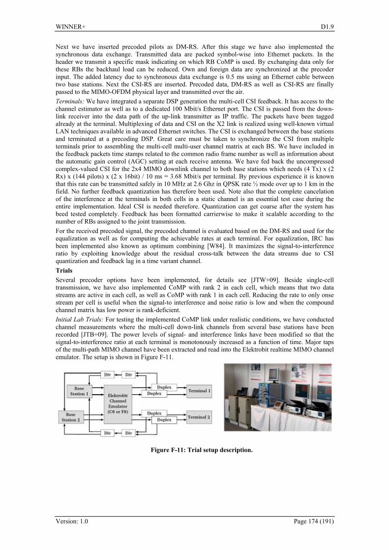
WINNER+ D1.9
Version: 1.0 Page 174 (191)
Next we have inserted precoded pilots as DM-RS. After this stage we have also implemented the synchronous data exchange. Transmitted data are packed symbol-wise into Ethernet packets. In the header we transmit a specific mask indicating on which RB CoMP is used. By exchanging data only for these RBs the backhaul load can be reduced. Own and foreign data are synchronized at the precoder input. The added latency due to synchronous data exchange is 0.5 ms using an Ethernet cable between two base stations. Next the CSI-RS are inserted. Precoded data, DM-RS as well as CSI-RS are finally passed to the MIMO-OFDM physical layer and transmitted over the air. Terminals: We have integrated a separate DSP generation the multi-cell CSI feedback. It has access to the channel estimator as well as to a dedicated 100 Mbit/s Ethernet port. The CSI is passed from the down-link receiver into the data path of the up-link transmitter as IP traffic. The packets have been tagged already at the terminal. Multiplexing of data and CSI on the X2 link is realized using well-known virtual LAN techniques available in advanced Ethernet switches. The CSI is exchanged between the base stations and terminated at a precoding DSP. Great care must be taken to synchronize the CSI from multiple terminals prior to assembling the multi-cell multi-user channel matrix at each BS. We have included in the feedback packets time stamps related to the common radio frame number as well as information about the automatic gain control (AGC) setting at each receive antenna. We have fed back the uncompressed complex-valued CSI for the 2x4 MIMO downlink channel to both base stations which needs (4 Tx) x (2 Rx) x (144 pilots) x (2 x 16bit) / 10 ms = 3.68 Mbit/s per terminal. By previous experience it is known that this rate can be transmitted safely in 10 MHz at 2.6 Ghz in QPSK rate ½ mode over up to 1 km in the field. No further feedback quantization has therefore been used. Note also that the complete cancelation of the interference at the terminals in both cells in a static channel is an essential test case during the entire implementation. Ideal CSI is needed therefore. Quantization can get coarse after the system has beed tested completely. Feedback has been formatted carrierwise to make it scalable according to the number of RBs assigned to the joint transmission. For the received precoded signal, the precoded channel is evaluated based on the DM-RS and used for the equalization as well as for computing the achievable rates at each terminal. For equalization, IRC has been implemented also known as optimum combining [W84]. It maximizes the signal-to-interference ratio by exploiting knowledge about the residual cross-talk between the data streams due to CSI quantization and feedback lag in a time variant channel. Trials Several precoder options have been implemented, for details see [JTW+09]. Beside single-cell transmission, we have also implemented CoMP with rank 2 in each cell, which means that two data streams are active in each cell, as well as CoMP with rank 1 in each cell. Reducing the rate to only onse stream per cell is useful when the signal-to interference and noise ratio is low and when the compound channel matrix has low power is rank-deficient. Initial Lab Trials: For testing the implemented CoMP link under realistic conditions, we have conducted channel measurements where the multi-cell down-link channels from several base stations have been recorded [JTB+09]. The power levels of signal- and interference links have been modified so that the signal-to-interference ratio at each terminal is monotonously increased as a function of time. Major taps of the multi-path MIMO channel have been extracted and read into the Elektrobit realtime MIMO channel emulator. The setup is shown in 406HFigure F-11.
Figure F-11: Trial setup description.

WINNER+ D1.9
Version: 1.0 Page 175 (191)
Figure F-12: Measured throughput of both terminals in both cells. The throughput has been measured for fixed multi-cell transmission modes, see 407HFigure F-12. Throughput results represent the so-called good-put, i.e. the rate of error-free data bits achieved using an uncoded bit error rate target of 0.025 in the link adaptation performed independently in each cell. In the interference-limited scenario (denoted as IRC in 408HFigure F-12) terminal 1 is in a critical scenario partly limited also by the noise. A measurable throughput can be realized with IRC only at SIR>10 dB. In the SIR range below 10 dB, CoMP can still achieve substantial throughputs which indicates the benefit at the cell edge where similar situations may be typical. With rising SIR, the throughput with CoMP using rank 1 per cell saturates while rank 2 transmission is not preferable for the terminal in this particular situation. The second terminal is mostly limited by interference. It achieves significant throughput using IRC at SIR>2dB already, but the throughput using CoMP is much higher in general. For CoMP with rank 2 per cell, terminal 2 indicates some saturation of the throughput at very high SIR > 20 dB. This is attributed to the time variance of the channel is not yet compensated. For terminal 2, we observe that CoMP with rank 2 per cell is preferable compared to CoMP with rank 1 per cell at an SIR above 15 dB, approximately. This reminds us to recent observations in single-cell multi-user MIMO systems, where multi-stream transmission becomes more likely than single-stream above an SNR of 15 dB. Multi-stream becomes more likely at SNR values even below 0 dB if there are 10 users in a cell. Over-the-air trials in the lab: Enabling CoMP trials over the air turned out as a second challenge. Therefore, several enhancements were needed in the system. Firstly, phase noise has been further reduced using a separate Rohde&Schwartz SMIQ local oscillator coupled to a 10 MHz GPS-disciplined Rubidium reference clock at at each base station instead of a common LO used previously inside both base stations. Secondly, power amplifier linearization has been turned off. It has caused infrequent but random phase hops at the transmit antenna antennas, eventually due to a calibration mismatch in the linearization algorithm. Thirdly, the measurement and optimization of the automatic gain control (AGC) has been improved. It is now measured during the time where the CSI-RS signals are transmitted and set during a short pause in the data transmission instead during regular, i.e. scheduled data transmission. In this way, multicell channel estimation became more stable and robust. Cross-talk between the estimates in both cells in case of strong interference has been reduced which has improved the overall performance. With these enhancements, over-the-air CoMP downlink transmission has been successfully tested. In an indoor environment, both cells have approximately equal power at both terminals, i.e. the expectation of the SINR is in the order of 0 dB or even less. No more data transmission is then normally possible in the presence of co-channel interference. With CoMP, co-channel interference is virtually switched off. Intermediate results indicate that even with rank 2 CoMP transmission in each cell and at a mean SINR of 0 dB, between 2/3 to 3/4 of the rate which could be realized in an isolated cell can also be realized in the presence of full co-channel interference if the joint precoder based on the CSI feedback is switched on. First oudoor experience: First CoMP trials have also been conducted outdoors meanwhile. In a first run, two sectors at the same site have been used and both terminals have been placed in the same van. This particular setting enables simultaneous decoding of the feedback channel from both terminals at each base stations also under outdoor conditions, i.e. power control as well as timing advance settings are valid for both terminals in both cells. First experiences indicate that CoMP works properly also under outdoor
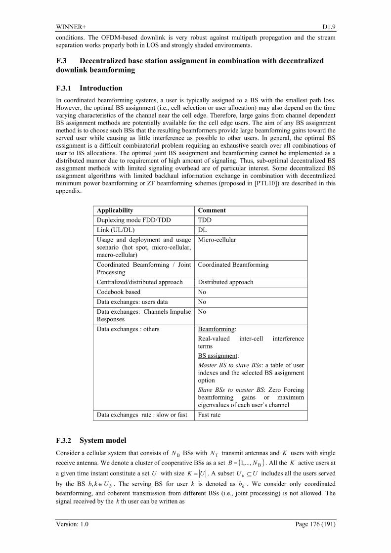
WINNER+ D1.9
Version: 1.0 Page 176 (191)
conditions. The OFDM-based downlink is very robust against multipath propagation and the stream separation works properly both in LOS and strongly shaded environments.
F.3 Decentralized base station assignment in combination with decentralized downlink beamforming
F.3.1 Introduction In coordinated beamforming systems, a user is typically assigned to a BS with the smallest path loss. However, the optimal BS assignment (i.e., cell selection or user allocation) may also depend on the time varying characteristics of the channel near the cell edge. Therefore, large gains from channel dependent BS assignment methods are potentially available for the cell edge users. The aim of any BS assignment method is to choose such BSs that the resulting beamformers provide large beamforming gains toward the served user while causing as little interference as possible to other users. In general, the optimal BS assignment is a difficult combinatorial problem requiring an exhaustive search over all combinations of user to BS allocations. The optimal joint BS assignment and beamforming cannot be implemented as a distributed manner due to requirement of high amount of signaling. Thus, sub-optimal decentralized BS assignment methods with limited signaling overhead are of particular interest. Some decentralized BS assignment algorithms with limited backhaul information exchange in combination with decentralized minimum power beamforming or ZF beamforming schemes (proposed in [PTL10]) are described in this appendix.
Applicability Comment Duplexing mode FDD/TDD TDD Link (UL/DL) DL Usage and deployment and usage scenario (hot spot, micro-cellular, macro-cellular)
Micro-cellular
Coordinated Beamforming / Joint Processing
Coordinated Beamforming
Centralized/distributed approach Distributed approach Codebook based No Data exchanges: users data No Data exchanges: Channels Impulse Responses
No
Data exchanges : others
Beamforming: Real-valued inter-cell interference terms BS assignment: Master BS to slave BSs: a table of user indexes and the selected BS assignment option Slave BSs to master BS: Zero Forcing beamforming gains or maximum eigenvalues of each user’s channel
Data exchanges rate : slow or fast Fast rate
F.3.2 System model Consider a cellular system that consists of BN BSs with TN transmit antennas and K users with single receive antenna. We denote a cluster of cooperative BSs as a set B,...,1 NB = . All the K active users at a given time instant constitute a set U with size UK = . A subset UU b ⊆ includes all the users served by the BS bUkb ∈, . The serving BS for user k is denoted as kb . We consider only coordinated beamforming, and coherent transmission from different BSs (i.e., joint processing) is not allowed. The signal received by the k th user can be written as

WINNER+ D1.9
Version: 1.0 Page 177 (191)
kkii
ibkbkbkbk nyiikk
++= ∑≠= ,1
,,,, xhxh
where T1,
Nkb C
k
×∈h is the channel gain vector from BS kb to user k , 1,
TC ×∈ Nkbk
x is the transmitted
signal vector from BS kb to user k and kn ~ ),0( 0NCN is the additive noise sample with zero mean and 0N variance.
The channel gain between BS kb and user k is given by kbkbkb kkka ,,, hh = , where kbk
a , is the large-
scale fading coefficient and kbk ,h is the complex valued channel vector with elements modelled as i.i.d. Gaussian random variables having unit variance. The transmitted signal vector from kb th BS to user k is
expressed as kkbkb dkk ,, mx = , where 1
,TC ×∈ N
kbkm is the transmit beamforming vector and kd is the
normalized complex data symbol with power [ ] 1dE 2k = . The total transmit power of the BS b is given
by
[ ]( ) ∑∑∈∈
=bb Uk
kbkbkbUk
2
2,H
,,ETr mxx
The SINR of the user k can be expressed as
∑∑
∑
∈∈
≠=
++
=
+
=Γ
K
kUiibkb
Bbkb
kbkb
K
kiiibkb
kbkbk
kb
ii
kk
ii
kk
N
N
\
2,,
2,0
2,,
,1
2,,0
2,,
ζ mh
mh
mh
mh
where 2
,,2
,ζ ∑∈
=bUi
ibkbkb mh , bUk ∉∀ , b∀ denotes the real valued inter-cell interference term from BS
b to user k and kbBB \= .
F.3.3 Optimal joint minimum power beamforming and BS assignment
A set aK
aa bb ,...,1=Α with size Ka =Α includes the fixed BS assignments for each active user k for a
given BS assignment set index a , Aa ,...,1= . The total number of different BS assignment sets aΑ depends on the number of users K and BSs BN in a given cluster B . A set a
bU includes all the users
served by the BS b , abUk ∈ for a given user to BS assignment set aΑ . Now, the problem for optimal
multi-cell minimum power beamforming and BS assignment can be formulated, and the BS assignment set that provides the minimum sum power can be found by solving the following problem
k
a
k
N
b Ukkb
Aa ab
kb
∀≥Γ
= ∑ ∑= ∈≤≤
, s.t.
minargmin
k
1
2
2,1
min
B
,
γ
mm
The optimal minimum power beamforming and BS assignment can be achieved using either an exhaustive search over all possible combinations of user to BS allocations or an iterative uplink downlink duality based algorithm from [Ben01].
F.3.4 Decentralized beamforming schemes Decentralized multi-cell minimum power beamforming and ZF beamforming techniques for a fixed user to BS assignment are described. The centralized version of the general problem of minimizing the sum power subject to fixed user-specific SINR constraints can be expressed as [TPK09b]
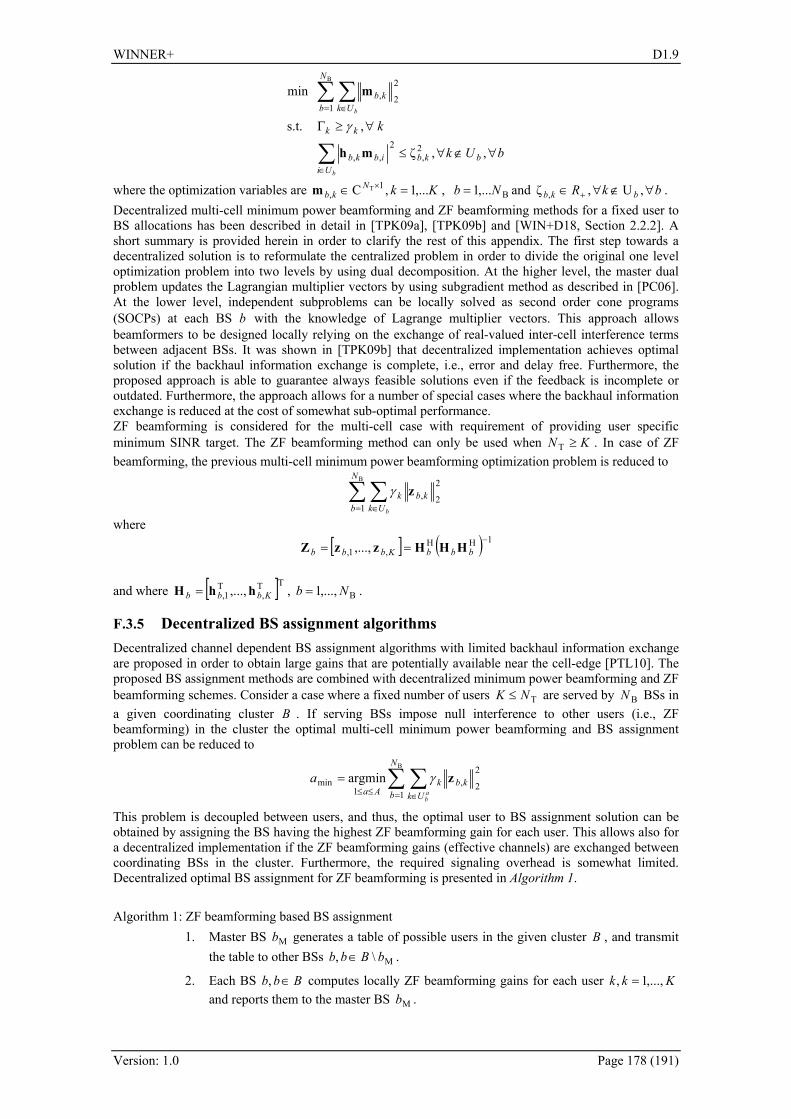
WINNER+ D1.9
Version: 1.0 Page 178 (191)
bUk
k
bkbUi
ibkb
kk
N
b Ukkb
b
b
∀∉∀≤
∀≥Γ
∑
∑ ∑
∈
= ∈
,,ζ
, s.t.
min
2,
2,,
1
2
2,
B
mh
m
γ
where the optimization variables are KkNkb ,...1,C 1
,T =∈ ×m , B,...1 Nb = and bkR bkb ∀∉∀∈ + ,U,ζ , .
Decentralized multi-cell minimum power beamforming and ZF beamforming methods for a fixed user to BS allocations has been described in detail in [TPK09a], [TPK09b] and [WIN+D18, Section 2.2.2]. A short summary is provided herein in order to clarify the rest of this appendix. The first step towards a decentralized solution is to reformulate the centralized problem in order to divide the original one level optimization problem into two levels by using dual decomposition. At the higher level, the master dual problem updates the Lagrangian multiplier vectors by using subgradient method as described in [PC06]. At the lower level, independent subproblems can be locally solved as second order cone programs (SOCPs) at each BS b with the knowledge of Lagrange multiplier vectors. This approach allows beamformers to be designed locally relying on the exchange of real-valued inter-cell interference terms between adjacent BSs. It was shown in [TPK09b] that decentralized implementation achieves optimal solution if the backhaul information exchange is complete, i.e., error and delay free. Furthermore, the proposed approach is able to guarantee always feasible solutions even if the feedback is incomplete or outdated. Furthermore, the approach allows for a number of special cases where the backhaul information exchange is reduced at the cost of somewhat sub-optimal performance. ZF beamforming is considered for the multi-cell case with requirement of providing user specific minimum SINR target. The ZF beamforming method can only be used when KN ≥T . In case of ZF beamforming, the previous multi-cell minimum power beamforming optimization problem is reduced to
∑ ∑= ∈
B
1
2
2,
N
b Ukkbk
b
zγ
where
[ ] ( ) 1HH,1, ,...,
−== bbbKbbb HHHzzZ
and where [ ]TT,
T1, ,..., Kbbb hhH = , B,...,1 Nb = .
F.3.5 Decentralized BS assignment algorithms Decentralized channel dependent BS assignment algorithms with limited backhaul information exchange are proposed in order to obtain large gains that are potentially available near the cell-edge [PTL10]. The proposed BS assignment methods are combined with decentralized minimum power beamforming and ZF beamforming schemes. Consider a case where a fixed number of users TNK ≤ are served by BN BSs in a given coordinating cluster B . If serving BSs impose null interference to other users (i.e., ZF beamforming) in the cluster the optimal multi-cell minimum power beamforming and BS assignment problem can be reduced to
∑ ∑= ∈≤≤
=B
1
2
2,1
min argminN
b Ukkbk
Aa ab
a zγ
This problem is decoupled between users, and thus, the optimal user to BS assignment solution can be obtained by assigning the BS having the highest ZF beamforming gain for each user. This allows also for a decentralized implementation if the ZF beamforming gains (effective channels) are exchanged between coordinating BSs in the cluster. Furthermore, the required signaling overhead is somewhat limited. Decentralized optimal BS assignment for ZF beamforming is presented in Algorithm 1. Algorithm 1: ZF beamforming based BS assignment
1. Master BS Mb generates a table of possible users in the given cluster B , and transmit the table to other BSs M\, bBbb ∈ .
2. Each BS Bbb ∈, computes locally ZF beamforming gains for each user Kkk ,...,1, = and reports them to the master BS Mb .

WINNER+ D1.9
Version: 1.0 Page 179 (191)
3. Master BS Mb combines all the provided information and selects the user to BS
allocation option minaΑ which results in the lowest total power minP across the coordinated BSs.
4. Master BS Mb reports the selected allocation option minaΑ to other BSs M\, bBbb ∈ .
5. All BSs Bbb ∈, perform ZF beamforming according to the selected allocation option minaΑ .
Decentralized ZF beamforming and optimal BS assignment scheme achieves near optimal performance at the cell-edge area when the user-specific SINR constraints are high as can be seen from the simulation results. However, in the case of low SINR constraints, ZF beamforming and optimal BS assignment is highly sub-optimal even near the cell-edge. Hence, more efficient beamforming and BS assignment approaches are needed when user-specific SINR targets are low. One possible solution is to combine simple ZF beamforming based BS assignment and the optimal decentralized minimum power beamforming scheme. The implementation of the resulting method follows exactly Algorithm 1, except the step 5, where optimal minimum power beamforming is performed instead of ZF beamforming. Another simple and straightforward BS assignment method to be combined with optimal minimum power beamforming is maximum eigenvalue based BS assignment. In such a case, K user-BS pairs which channels' have the highest maximum eigenvalues are selected. This BS assignment approach will require the similar amount of backhaul information exchange than that of ZF beamforming based BS assignment scheme, and is especially meant for the cases where the user-specific SINR targets are low. The implementation of maximum eigenvalue based BS assignment is described in Algorithm 2. Algorithm 2: Maximum eigenvalue based BS assignment
1. Master BS Mb generates a table of possible users in the given cluster B , and transmit the table to other BSs M\, bBbb ∈ .
2. Each BS Bbb ∈, computes locally maximum eigenvalue for each user Kkk ,...,1, = and reports them to the master BS Mb .
3. Master BS Mb combines all the provided information and selects the TN largest
eigenvalues and the corresponding user to BS allocation option minaΑ .
4. Master BS Mb reports the selected allocation option minaΑ to other BSs M\, bBbb ∈ .
5. All BSs Bbb ∈, perform decentralized optimal minimum power beamforming according to the selected allocation option minaΑ .
Decentralized minimum power beamforming scheme can also be combined with regularized ZF beamforming based BS assignment approach. In regularized ZF beamforming, some interference between other users is allowed, and this interference is controlled by a regularization term. However, optimizing the regularization term over multiple BSs would require too much signaling overhead for allowing a distributed implementation. Hence, one solution how to use regularized ZF beamforming based BS assignment is to locally perform regularized beamforming with fixed common regularization term. This kind of approach will require only the same amount of signaling than that of the general ZF beamforming based BS assignment. Regularized ZF beamforming weights can be calculated at each BS as follows
[ ] ( ) ,,,...,1HHreg
,reg
1,reg bKbbbKbbb ∀+==
−IHHHzzZ ω
where ω is the regularization term. The implementation of regularized ZF beamforming based BS assignment is similar to that of in Algorithm 1, except in step 2 regularized ZF beamforming gains are calculated instead of general ZF beamforming gains. In addition, in step 5 decentralized minimum power beamforming is performed instead of ZF beamforming. However, the problem is to determine the fixed common regularization terω . In this work, we have used off-line simulations to determine the optimal regularization term for a certain scenario since any decentralized online optimization would require large amount of backhaul information exchange. Thus, the method is heuristic. Unfortunately, we were not yet able to find analytic proof for the optimal regularization term.

WINNER+ D1.9
Version: 1.0 Page 180 (191)
F.3.6 Simulation results A simplified multi-cell transmission scenario with frequency flat block fading is considered, where
4=K single antenna users are served simultaneously by 2 BSs. The number of antennas at each BS is 4T =N . The simulation scenario is depicted in 409HFigure F-13. For simplicity, it is assumed that all the
4=K users are divided into 2B =N groups with the same size. Within a single group, each user has identical large scale fading coefficients kba , , i.e., aaaaa ==== 4,23,22,11,1 . Path gain to noise ratio is
normalized to 102 =Na . We define a parameter α to denote the distance between different user
groups, i.e., α fixes the ratio of path losses between the different user groups, as illustrated in Fig. 1. For example, 2
1,22
3,22
3,121,1 aaaa ==α . A case where all the K users are located exactly at the cell edge can
be modeled by setting α to 0 dB. By setting ∞=α cells are totally isolated. In the simulation, the required sum power over BN BSs for fulfilling the fixed user-specific SINR constraint is calculated for different beamforming and BS assignment methods as a function of α . The distance α is varied from 0 to 20 dB in order to model different user group locations.
Figure F-13: Simulation scenario.
The following beamforming and BS assignment schemes are compared in the simulations:
1. Optimal centralized coordinated beamforming with a. Optimal centralized BS assignment
2. Optimal decentralized coordinated beamforming with a. Fixed BS assignment b. ZF beamforming based BS assignment c. Maximum eigenvalue based BS assignment d. Regularized ZF beamforming based BS assignment
3. ZF beamforming with a. Fixed BS assignment b. ZF beamforming based BS assignment
Fixed BS assignment denotes a case when a user k is always allocated to a cell b with the smallest path loss. 410HFigure F-14 illustrates the average sum power of 4,2,4,, TB =NNK system as a function of α , to meet 0 dB SINR constraint. All users have equal SINR constraints. It can be noticed that ZF beamforming with fixed BS assignment requires the highest sum power to fulfill 0 dB SINR targets. When ZF beamforming is combined with optimal decentralized BS assignment, the performance is improved considerably. However, the performance is much worse than that of decentralized coordinated beamforming with fixed BS assignment. As can be seen, there are large gains available near the cell edge if decentralized optimal minimum power beamforming method is combined with proper decentralized BS assignment method. Combining ZF beamforming based BS assignment scheme and optimal minimum power beamforming, the performance is somewhat better compared to fixed BS assignment case at the cell edge area. However, when the value of α increases, i.e., α ≥ 3 dB, the performance become even worse than in the case of fixed BS assignment. This is due to a fact that ZF beamforming based BS assignment is not primarily tailored to be combined with optimal minimum power beamforming scheme. Maximum eigenvalue based BS assignment in combination with optimal minimum power beamforming obtains much of the available gains near the cell-edge. This method will achieve the same performance than optimal BS assignment when α is large enough, i.e., in the case when the cells are almost isolated.

WINNER+ D1.9
Version: 1.0 Page 181 (191)
Regularized ZF beamforming based BS assignment slightly outperforms maximum eigenvalue based method near the cell-edge. However, the difference is quite marginal. Furthermore, maximum eigenvalue based BS assignment method has better performance when α ≥ 4 dB. For this particular scenario, the regularization term value was set to ω = 0.002 based on the off-line simulations over large amount of channel realizations. 411HFigure F-15 illustrates the average sum power of 4,2,4,, TB =NNK system as a function of α , to meet 20 dB SINR constraint. In this case, the user specific SINR targets are high and the results differ significantly from the previous case with low SINR targets. It is shown that simple ZF beamforming with optimal decentralized BS assignment obtains near optimal performance at the cell edge area. Thus, it can be concluded that it is preferable to use ZF beamforming with decentralized BS assignment near the cell-edge when user specific SINR targets are high. This is especially preferable when the user velocity is high or backhaul information exchange rate is low.
0 3 6 10 200
5
10
15
Distance α between different user groups [dB]
Pow
er [d
B]
ZF with fixed BS assignmentZF with optimal decentr. BS assignmentdecentr. CB with fixed BS assignmentdecentr. CB with ZF BS assignmentdecentr. CB with MAxEigVal BS assignmentdecentr. CB with RegZF BS assignmentcentr. CB with optimal BS assignment
Figure F-14: Average sum power of 4,2,4,, TB =NNK system for 0 dB SINR target.
0 3 6 10 2025
26
27
28
29
30
31
32
33
34
35
Distance α between different user groups [dB]
Pow
er [d
B]
ZF with fixed BS assignmentZF with optimal decentr. BS assignmentdecentr. CB with fixed BS assignmentcentr. CB with optimal BS assignment
Figure F-15: Average sum power of 4,2,4,, TB =NNK system for 20 dB SINR target.

WINNER+ D1.9
Version: 1.0 Page 182 (191)
F.3.7 Conclusions Decentralized BS assignment methods with limited backhaul information exchange in combination with decentralized beamforming approaches were introduced. The goal of the combined BS assignment and beamforming was to minimize the total transmitted power subject to fixed user-specific SINR constraints while limiting the backhaul information exchange. The simulation results showed that a simple ZF beamforming in combination with optimal decentralized BS assignment with limited signaling overhead can obtain near optimal performance near the cell edge when the fixed user specific SINR targets are high. Thus, only marginal gains are available for more complex BS assignment and beamforming methods at the cell edge. Furthermore, in the case of low user specific SINR targets, it was shown that much of the gain which is available near the cell edge could be achieved when using, e.g., a simple maximum eigenvalue based BS assignment method with limited backhaul information exchange.

WINNER+ D1.9
Version: 1.0 Page 183 (191)
G. Appendix – Innovation Tracing WINNER+ issued a short living document to trace all the innovations proposed by the partners in WINNER+. This "innovation tracing" document is used to ensure that we do not lose inadvertendly interesting ideas, are aware of where and how the various concepts are treated, get indication about the innovations timeliness regarding the LTE-A and ITU process, prepare the future steps, etc.. The following table sums up the references, with origin and paragraph of the corresponding deliverable, of the innovations presented to WINNER+ from the beginning of the project.
Innovations D1.1 D4.1 D2.1 D1.5 D1.9 traffic-aware score-based scheduling 2.2 7 2.2.1.1 QoS scheduler based on utility prediction 2.3 3.2 7 2.2.1.2 relay-capable scheduling for combined full-/half-duplex FDD
2.4 3.3 6 5.2.1.1
relay-capable CQI signalling for frequency adaptive scheduling
2.5 3.4 6 8.2.4
MU diversity scheduling for SDMA systems 5.2 7 7.3.3 dynamic load management and congestion control 3.3 3.6 7 2.2.4.3 automatic traffic characterisation 3.4 3.5 7 2.2.4.1 recursive nonlinear traffic prediction for dynamic resource allocation
3.5 7 2.2.4.2
HYGIENE scheduling for OFDMA wireless cellular networks
2.2 5.2.1.3
interference mitigation (CoMP) based on efficient scheduling
2.3 2.2.2.2
decentralised interference avoidance using busy bursts 3.2 7 2.4 2.2.2.3 cross-layer relay-capable flow management for QoS scheduling
3.2 5.2.1.2
cross-layer optimisation for rate-adaptive applications 2.6 7 3.3 8.2.2 joint resource allocation-admission control 3.4 8.2.3 spectrum aggregation from the physical layer perspective 4.2 3.2.2 spectrum aggregation from the scheduling perspective 4.3 3.2.1 CQI signalling in carrier aggregation 4.4 3.2.3 multicast and broadcast repair services 4 7 5 2.2.5,
A.3 power efficient uplink transmission 6 10.2 a closed loop MAC layer 2.2.1 D1.2 D1.6 intra-operator spectrum sharing and femto cells 4 8 2 4.2.1 uncoordinated femtocell deployment 5 4.2.2 self organized femtocells 5 8 3 4.2.3
B.3 spectrum sharing from a game theory perspective 6 8 4 2.2.3.1 optimisation of the sum throughput 5 2.2.3.2 femtocells and game theory 4.2.4,
B.3 D1.3 D1.7 P2P communications 2 10.1 multi-user linear precoding based on long-term channel state information
3.1.1 7.3.3
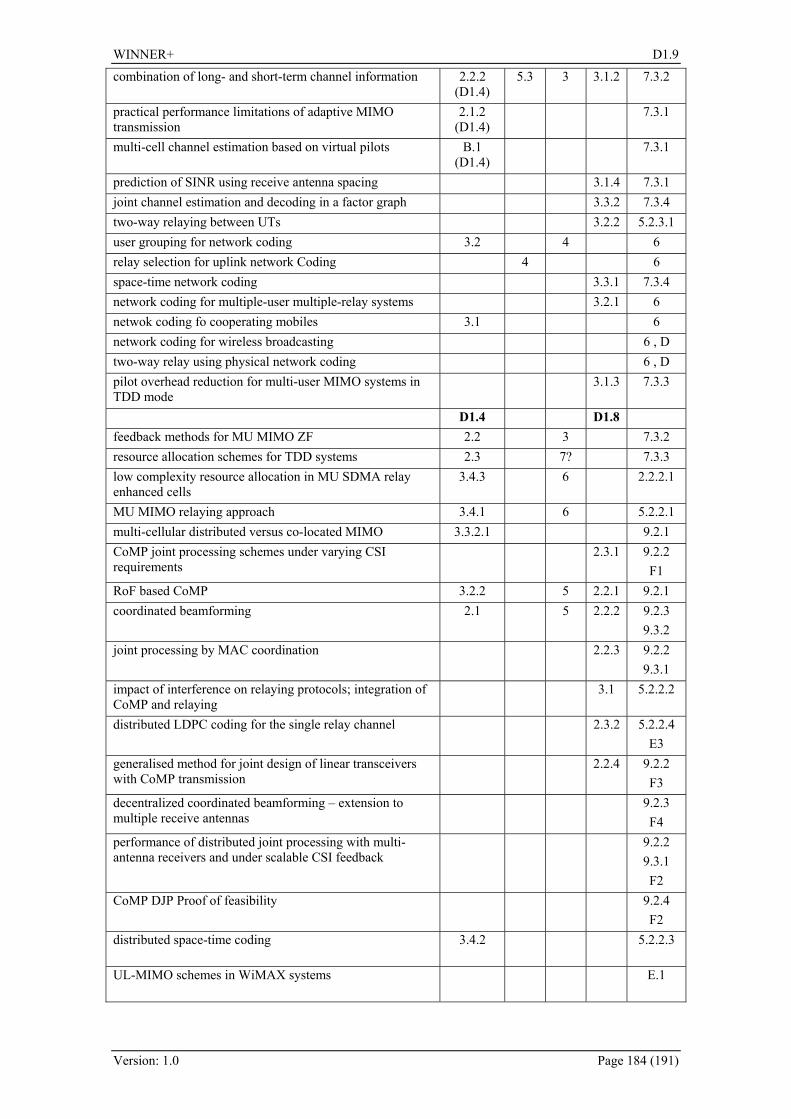
WINNER+ D1.9
Version: 1.0 Page 184 (191)
combination of long- and short-term channel information 2.2.2 (D1.4)
5.3 3 3.1.2 7.3.2
practical performance limitations of adaptive MIMO transmission
2.1.2 (D1.4)
7.3.1
multi-cell channel estimation based on virtual pilots B.1 (D1.4)
7.3.1
prediction of SINR using receive antenna spacing 3.1.4 7.3.1 joint channel estimation and decoding in a factor graph 3.3.2 7.3.4 two-way relaying between UTs 3.2.2 5.2.3.1 user grouping for network coding 3.2 4 6 relay selection for uplink network Coding 4 6 space-time network coding 3.3.1 7.3.4 network coding for multiple-user multiple-relay systems 3.2.1 6 netwok coding fo cooperating mobiles 3.1 6 network coding for wireless broadcasting 6 , D two-way relay using physical network coding 6 , D pilot overhead reduction for multi-user MIMO systems in TDD mode
3.1.3 7.3.3
D1.4 D1.8 feedback methods for MU MIMO ZF 2.2 3 7.3.2 resource allocation schemes for TDD systems 2.3 7? 7.3.3 low complexity resource allocation in MU SDMA relay enhanced cells
3.4.3 6 2.2.2.1
MU MIMO relaying approach 3.4.1 6 5.2.2.1 multi-cellular distributed versus co-located MIMO 3.3.2.1 9.2.1 CoMP joint processing schemes under varying CSI requirements
2.3.1 9.2.2 F1
RoF based CoMP 3.2.2 5 2.2.1 9.2.1 coordinated beamforming 2.1 5 2.2.2 9.2.3
9.3.2 joint processing by MAC coordination 2.2.3 9.2.2
9.3.1 impact of interference on relaying protocols; integration of CoMP and relaying
3.1 5.2.2.2
distributed LDPC coding for the single relay channel 2.3.2 5.2.2.4 E3
generalised method for joint design of linear transceivers with CoMP transmission
2.2.4 9.2.2 F3
decentralized coordinated beamforming – extension to multiple receive antennas
9.2.3 F4
performance of distributed joint processing with multi-antenna receivers and under scalable CSI feedback
9.2.2 9.3.1 F2
CoMP DJP Proof of feasibility 9.2.4 F2
distributed space-time coding 3.4.2 5.2.2.3
UL-MIMO schemes in WiMAX systems E.1
WINNER+ D1.9
Version: 1.0 Page 185 (191)
References [3GPP36211] 3GPP TS 36.211, ”Evolved Universal Terrestrial Radio Access (E-UTRA);Physical
Channels and Modulation “, V8.8.0, Sep. 2009. [3GPP36213] 3GPP TS 36.213, “Evolved Universal Terrestrial Radio Access (E-UTRA); Physical
Layer Procedures (Release 8)”. [3GPP36300] 3GPP TS 36.300, ” Evolved Universal Terrestrial Radio Access (E-UTRA) and Evolved
Universal Terrestrial Radio Access Network (E-UTRAN); Overall description; Stage 2“, V8.7.0, Dec. 2008.
[3GPP36814] 3GPP TR 36.814, "Further Advancements for E-UTRA Physical Layer Aspects", V1.0.0, Mar. 2009.
[3GPP36814v140] 3GPP TR 36.814, "Further Advancements for E-UTRA Physical Layer Aspects", V1.4.0.
[3GPP36912] 3GPP TR 36.912, ”Feasibility study for Further Advancements for E-UTRA (LTE-Advanced) “, V9.0.0, Sep. 2009.
[3GPP-R1091066] 3GPP, CATT, CMCC, Ericsson, Huawei, LGE, Motorola, Nokia, Nokia Siemens Networks, Nortel, Panasonic, Philips, Qualcomm Europe, Samsung, Texas Instruments. Way forward on downlink reference signals for LTE-A, R1-091066.
[3GPP-R1091483] 3GPP, NTT Docomo. DL RS Design for LTE-Advanced, R1-091483. [3GPP-TR25996] 3GPP TR 25.996 V7.0.0, “Spatial channel model for multiple input multiple output
(MIMO) simulations,” July 2007. [ACL+00] R. Ahlswede, N. Cai, S.-Y. R. Li and R. W. Yeung, Network information flow, IEEE
Trans. Information Theory, July 2000 [AGS05] K. Azarian, H. El Gamal, and P. Schniter , “On the achievable diversity-multiplexing
tradeoff in half-duplex cooperative channels”, IEEE Transactions on Information Theory, December 2005.
[AOZ10] Arif Otyakmaz, "Multi-Hop Cellular Radio Network Integrating Frequency and Time Duplexing", PhD thesis ComNets, RWTH Aachen, Germany, 2010
[AVG+09] G. Auer, S. Videv, B. Ghimire and H. Haas, “Contention Free Inter-Cellular Slot Reservation”, IEEE Communication Letters, pp. 318-320, vol. 13, May 2009.
[BEG05] H. J. Bang, T. Ekman, D. Gesbert, “A Channel Predictive Proportional Fair Scheduling Algorithm”, in proceeding of SPAWC 2005, New York, June 2005.
[BEG06] H. J. Bang, T. Ekman, D. Gesbert, “Channel Predictive Proportional Fair Scheduling”, IEEE Transaction on Wireless Communication, submitted the 20th of September 2006.
[Ben01] M. Bengtsson, “Jointly optimal downlink beamforming and base station assignment”, in Proceedings of the IEEE International Conference on Acoustic, Speech and Signal Processing, Salt Lake City, USA, May 2001.
[Ber03] D.P. Bertsekas, “Nonlinear programming”, 2nd edition, Belmont, Mass: Athena Scientific, 2003.
[BLD09] M. Bennis, S. Lasaulce and M. Debbah, “Inter operator spectrum sharing from a game theroretical perspective,” EURASIP Journal of Advances in Signal Processing (JASP), Special issue on dynamic spectrum access for wireless networking, 2009, 2009, 1-12, August, Article ID 295739, doi:10.1155/2009/29573,[BH07] F. Boccardi, H. Huang. A Near-Optimum Technique using Linear Precoding for the MIMO Broadcast Channel. Acoustics, Speech and Signal Processing, 2007. ICASSP 2007. IEEE International Conference on, 3:III-17-III-20, 2007.
[BHA08] F. Boccardi, H. Huang and A. Alexiou, “Network MIMO with reduced backhaul requirements by MAC coordination”, in Proc. of Asilomar, 2008.
[BMKS09] Bültmann, D., Mühleisen, M., Klagges, K. and Schinnenburg, M., “openWNS – open Wireless Network Simulator”, in 15th European Wireless Conference, Aalborg, Denmark, May 2009
[Bon04] T. Bonald, “A Score-Based Opportunistic Scheduler for Fading Radio Channels”, in Proceedings of the European Wireless Conference, Barcelona, February 2004.
[BPG+08] C. Botella, G. Piñero, A. González and M. de Diego, “Coordination in a multi-cell multi-antenna multi-user W-CDMA system: a beamforming approach”, IEEE Transactions on Wireless Communications, November 2008.
WINNER+ D1.9
Version: 1.0 Page 186 (191)
[BSMKH05] D. S. Baum, J. Salo, M. Milojevic, P. Kyösti and J. Hansen. MATLAB implementation of the interim channel model for beyond-3G systems (SCME). Online. Available: http://www.tkk.fi/Units/Radio/scm/, 2005
[CA08] Vikram Chandrasekhar and Jeffrey G. Andrews, “Femtocell Networks: A Survey,” [IEEE80216m] IEEE 802.16m System Description Document (SDD), September 2009.
[CCK09] Emilio Calvanese-Strinati, Giorgio Corbellini, Dimitri Kténas, “HYGIENE Scheduling for OFDMA Wireless Cellular Networks”, IEEE 69th Vehicular Technology Conference (VTC) Spring 2009, 26–29 April 2009, Barcelona, Spain.
[CDG00] S. Catreux, P. Driessen, and L. Greenstein, “Simulation results for an interference-limited multiple input multiple output cellular system,”IEEE Communications Letters, vol. 4, pp. 334 – 336, November 2000.
[CDS96] L. J. Cimini, Jr., B. Daneshrad, and N. R. Sollenberger, “Clustered OFDM with transmitter diversity and coding,” in Proc. Globecom’96, London, UK, Nov. 1996, pp. 703-707.
[Cha09] Vikram Chandrasekhar, Coexistence in Femtocell-aided Cellular Architectures, PhD dissertation, The University of Texas at Austin, May 2009.
[CKL06] Y. Chen, S. Kirshore, and J. Li, “Wireless diversity through network coding,” in Proceedings of IEEE Wireless communications and networking conference, 2006.
[CLH04] S. T. Chung, A. Lozano, H. C. Huang, A. Sutivong, and J. M. Cioffi, “Approaching the MIMO capacity with a low-rate feedback channel in V-BLAST,” EURASIP Journal on Applied Signal Processing, vol. 5, pp.762–771, 2004.
[CS03] G. Caire and S. S. (Shitz), “On the achievable throughput of a multiantenna Gaussian broadcast channel,” IEEE Transactions on Information Theory, vol. 49, no. 7, pp. 1691–1706, July 2003.
[DPS+08] E. Dahlman, S. Parkvall, J. Sköld, and P. Beming, 3G Evolution: HSPA and LTE for Mobile Broadband, 2nd Ed., Academic Press, London, 2008
[DY08] H. Dahrouj and W. Yu, “Coordinated Beamforming for the Multi-Cell Multi-Antenna Wireless System,” in Proc. of the Conference on Information Sciences and Systems CISS, Mar. 2008, pp. 429–434.
[FDH05b] M. Fuchs, G. Del Galdo, and M. Haardt, ”Low complexity space-time-frequency scheduling for MIMO systems with SDMA”, IEEE Transactions on Vehicular Technology September 2007.
[FS07] C. Fragouli, E. Soljanin, Network Coding Fundamentals, Now Publishers, 2007. [GAH08] B. Ghimire, G. Auer and H. Haas, “Busy Bursts for Trading-off Throughput and
Fairness in Cellular OFDMA-TDD,” EURASIP Journal on Wireless Communications and Networking, 2008.
[GAH09a] B. Ghimire, G. Auer, and H. Haas, “Busy Bursts for Trading off Throughput and Fairness in Cellular OFDMA-TDD,” EURASIP J. Wireless Commun. and Networking, vol. 2009, Article ID 462396, 14 pages, 2009.
[GAH09b] B. Ghimire, G. Auer, and H. Haas, “OFDMA-TDD Networks with Busy Burst Enabled Grid-of-Beam Selection,” in Proc. IEEE Int. Conference on Communications (ICC 2009), Dresden, Germany, June 2009.
[GES07] J. Gozalvez, M. C. L. Estan, and J. S. Soriano, “User QoS-based multi-channel assignment schemes under multimedia traffic conditions,” in Proc. IEEE Int. Symposium on Wireless Communication Systems (ISWCS’2007), Trondheim, Norway, Oct. 17-19, 2007.
[GKHCS07] D. Gesbert, M. Kountouris, R. Heath, C.-B. Chae, and T. Salzer,“Shifting the MIMO paradigm,” IEEE Signal Processing Magazine,vol. 24, no. 5, pp. 36–46, Sept. 2007.
[HK81] T. Han and K. Kobayashi, “A new achievable rate region for the interference channel,” IEEE Transactions on Information Theory, vol. IT-27, no. 1, pp. 49–60, January 1981
[HL08] T. Ho, D. S. Lun, Network coding, Cambridge University Press, 2008 [HP05] R. Heath and A. J. Paulraj, “Switching between diversity and multiplexing in MIMO
systems,” IEEE Transactions on Communications, vol. 53, no. 6, 2005. [HT09] H. Holma and A. Toskala, LTE for UMTS – OFDMA and SC-FDMA Based Radio
Access, Wiley 2009. [HVKS03] H. Huang, S. Venkatesan, A. Kogiantis, and N. Sharma, “Increasing the peak data rate
of 3G downlink packet data systems using multiple antennas,” Vehicular Technology

WINNER+ D1.9
Version: 1.0 Page 187 (191)
Conference, 2003. VTC 2003-Spring. The 57th IEEE Semiannual, vol. 1, pp. 311–315 vol.1, april 2003.
[IEEE16e05] IEEE 802.16-2005: IEEE Standard for Local and Metropolitan Area Networks – Part 16: Air Interface for Fixed and Mobile Broadband Wireless Access Systems – Amendment 2: Physical Layer and Medium Access Control Layers for Combined Fixed and Mobile Operation in Licensed Bands, Feb. 2006.
[JJJT+09] S. Jaeckel, L. Jiang, V. Jungnickel, L. Thiele, C. Jandura, G. Sommerkorn and C. Schneider. Correlation properties of large and small-scale parameters from multicell channel measurements. 2009. invited.
[JJJ+09] V. Jungnickel, M. Schellmann, L. Thiele, T. Wirth, T. Haustein, O. Koch, W. Zirwas, and E. Schulz, “Interference-Aware Scheduling in the Multi-user MIMO-OFDM Downlink,” IEEE Communicaions Magazine, 2009.
[JJT+09] V. Jungnickel, S. Jaeckel, L. Thiele, L: Jiang, U. Krüger, A. Brylka and C. von Helmolt. Capacity Measurements in a Cooperative MIMO Network. Vehicular Technology, IEEE Transactions on, 58(5):2392-2405, 2009.
[JTB+09] S. Jaeckel, L. Thiele, A. Brylka, L. Jiang, V. Jungnickel, J. Heft and C. Jandura. Intercell Interference Measured in Urban Areas. IEEE International Conference on Communications (ICC), 2009. submitted.
[JTS+08] V. Jungnickel, L. Thiele, M. Schellmann, T. Wirth, W. Zirwas, T. Haustein and E. Schulz. Implementation Concepts for Distributed Cooperative Transmission. 42nd Asilomar Conference on Signals, Systems and Computers, 2008.
[JTW+09] V. Jungnickel, L. Thiele, T. Wirth, T. Haustein, S. Schiffermüller, A. Forck, S. Wahls, S. Jaeckel, S. Schubert, C. Juchems, F. Luhn, R. Zavrtak, H. Droste, G. Kadel, W. Kreher, J. Mueller, W. Stoermer and G. Wannemacher. Coordinated Multipoint Trials in the Downlink. Proc. 5th IEEE Broadband Wireless Access Workshop (BWAWS), co-located with IEEE GLOBECOM 2009, Honolulu, Hawai, 2009. to appear.
[JWS+08] V. Jungnickel and T. Wirth and M. Schellmann and T. Haustein and W. Zirwas. Synchronization of cooperative base stations. Proc. IEEE ISWCS '08, :329 - 334, 2008.
[KDS+06] S. Khan, S. Duhovnikov, E. Steinbach et al., “Application-driven Cross- layer Optimization for Mobile Multimedia Communication using a Common Application Layer Quality Metric,” in Second International Symposium on Multimedia over Wireless (ISMW'06), Vancouver, Canada, Jul. 2006.
[KDT09] T. Koike-Akino, N. Devroye, and V. Tarokh, Frequency-Domain Bit-Flipping Equalizer for Wideband MIMO Channels, IEEE trans. Wireless Communications, Vol. 8, No. 10, October 2009, pp. 4969-4973.
[KFL01] F.R. Kschischang, B.J. Frey, and H.-A. Loeliger, “Factor graphs and the sum-product algorithm,” IEEE Trans. On Information Theory, vol. 47, no. 2, pp. 498-519, Feb. 2001.
[KPT09] T. Koike-Akino, P. Popovski, V. Tarokh, “Optimized Constellations for Two–Way Wireless Relaying with Physical Network Coding”, IEEE Journal on Selected Areas in Communications, Vol. 27, No. 5, June 2009
[KYF09] Knisely, Yoshizawa, Favichia, “Standardization of Femtocells in 3GPP,” IEEE Comm. Magazine, September 2009, pp 68—75.
[Lar07] Peter Larsson, “Joint power and rate control for delay tolerant traffic in a wireless system,” Proc. IEEE Vehicular Technology Conference, pp. 2822-2826, Apr. 2007.
[LBB08] Y. Liu, L. Brunel, J. Boutros, “EM channel estimation for coded OFDM transmissions over frequency-selective channel,” in Proc. IEEE ISSSTA’08, Aug. 2008, p. 544-549.
[LJS06] P. Larsson, N. Johansson, and K.-E. Sunnel, Coded Bi-Directional Relaying, Proc. of IEEE VTC 2006 Spring, pp. 851-855
[M.2134] ITU-R, M.2134, “Requirements related to technical performance for IMT Advanced radio interface(s)”.
[MMA+08] F. Meucci, A. Mihovska, B. Anggorojati, N.R. Prasad, “Joint Resource Allocation for an OFDMA-Based System,” in, Proc. of WPMC ’08 Lapland, Finland, September, 2008.
[MOS08] J. Manssour, A. Osseiran and S. Ben Slimane, “Wireless Network Coding in Multi-Cell Networks: Analysis and Performance”, International Conference on Signal Processing and Communication Systems, ICSPCS’2008, Gold Coast, Australia, December 2008.

WINNER+ D1.9
Version: 1.0 Page 188 (191)
[MOS09] J. Manssour, A. Osseiran and S. Ben Slimane, “Opportunistic Relay Selection for Wireless Network Coding”, IEEE MICC 2009 , Kuala Lumpur, Malaysia, December 2009.
[MOS10] J. Manssour, A. Osseiran and S. Ben Slimane, “High-Rate Redundant Space-Time Coding”, Hindawi Journal of Electrical and Computer Engineering, to appear, 2010.
[OHA07] P. Omiyi, H. Haas, and G. Auer, “Analysis of TDD Cellular Interference Mitigation Using Busy-Bursts,” IEEE Transactions on Wireless Communications, vol. 6, no. 7, pp. 2721–2731, July 2007.
[OSJ+07] A. Osseiran, V. Stankovic, E. Jorswieck, T. Wild, M. Fuchs, and M. Olsson, “A MIMO Framework for 4G Systems: WINNER Concept and Results,” Proc. IEEE Workshop Signal Processing Advances Wireless Commun. (SPAWC 2007), Helsinki, Finland, June 2007.
[OSW08] A. Otyakmaz, R. Schoenen and B. Walke, “Parallel Operation of Half- and Full-Duplex FDD in Future Multi-Hop Mobile radio Networks”, in Proceedings of the European Wireless Conference, Prague, June 2008.
[OSW09] A. Otyakmaz, R. Schoenen, “On Flow Management for Future Multi-Hop Mobile Radio Networks”, Proceedings of the IEEE WiCom, Beijing, China, Sep 2009
[PBG+08] A. Papadogiannis, H.J. Bang, D. Gesbert and E. Hardouin, “Downlink overhead reduction for multi-cell cooperative processing enabled wireless networks”, in Proc. of PIMRC, 2008.
[PC06] D.P. Palomar and M. Chiang, “A tutorial on decomposition methods for network utility maximization,” IEEE J. on Select. Areas Commun., vol 24, no. 8, pp. 1439 – 1451, August 2006.
[PHG09] A. Papadogiannis,E. Hardouin, D. Gesbert. Decentralising multi-cell cooperative processing on the downlink : a novel robust framework. EURASIP Journal on Wireless Communications and Networking, Special Issue on Broadband Wireless Access,, 2009.
[PTL10] H. Pennanen, A. Tölli and M. Latva-aho, ”Decentralized base station assignment in combination with downlink beamforming” IEEE International Workshop on Signal Processing Advances in Wireless Communications, Marrakech, Morocco, June 2010, submitted.
[REC04] RECOMMENDATION ITU-R M.1645, “Framework and Overall Objectives of the Future Development of IMT 2000 and Systems Beyond IMT 2000,” 2004.
[RF10] P. Rost and G. Fettweis, “Green Communications in Cellular Networks with Fixe Relay
Nodes”, to appear in Cooperative Cellular Wireless Networks, Cambridge University Press, eds. E. Hossain and V. Bhargava, to be published in September 2010.
[RFL09] P. Rost, G. Fettweis, and J. Laneman, “Opportunities, constraints, and benefits of relaying in the presence of interference,” IEEE International Conference on Communications, Dresden, Germany, June 2009
[RH09a] F. Roemer and M. Haardt, “Tensor-Based channel estimation (TENCE) for Two-Way relaying with multiple antennas and spatial reuse,” in Proceedings of IEEE Int. Conf. Acoust., Speech, and Signal Processing (ICASSP), Taipei, Taiwan, Apr. 2009, invited paper.
[RH09b] F. Roemer and M. Haardt, “Structured least squares (SLS) based enhancements of tensor-based channel estimation (TENCE) for two-way relaying with multiple antennas,” in Proceedings of International ITG Workshop on Smart Antennas (WSA 2009), Berlin, Germany, Feb. 2009
[RH09c] F. Roemer and M. Haardt, “Algebraic norm-maximizing (ANOMAX) transmit strategy for two-way relaying with MIMO amplify and forward relays,” IEEE Signal Processing Letters, vol. 16, issue 10, pp. 909-912, Oct 2009.
[RH10] F. Roemer and M. Haardt, “A low-complexity relay transmit strategy for two-way relaying with MIMO amplify and forward relays,”. IEEE Int. Conference on Acoustics, Speech, and Signal Processing (ICASSP), (Dallas, TX), Mar. 2010.
[Ros09] P.Rost, “Opportunities, Benefits, and Constraints of Relaying in Mobile Communication Systems”, Vogt Verlag, ISBN 978-3-938860-23-6, 2009.
[Sau08] A. Saul, “Wireless resource allocation with perceived quality fairness,” in Proc. Asilomar Conference on Signals, Systems, and Computers, Pacific Grove, California, Oct. 26-29, 2008 (in press).

WINNER+ D1.9
Version: 1.0 Page 189 (191)
[SBS+09] S. Sinanovi´c, H. Burchardt, N. Serafimovski, G. Auer, and H. Haas, “Local Information Busy Burst Thresholding,” in Proc. International Conference on Communications (ICC’09), Dresden, Germany, Jun. 14–18 2009.
[SMW07] H. Schwarz, D. Marpe, and T. Wiegand, „Overview of the Scalable Video Coding Extension of the H.264/AVC Standard,” IEEE Transactions on Circuits and Systems for Video Technology, vol. 17, no. 9, September 2007.
[SOQ09] R. Schoenen, A. Otyakmaz, and F. Qin, “Adaptive Power Control for 4G OFDMA systems on Frequency Selective Fading Channels”, in Proceedings of the IEEE WiCom, Beijing, China, Sep 2009.
[STJH07] M. Schellmann, L. Thiele, V. Jungnickel, and T. Haustein, “A fair scorebased scheduler for spatial transmission mode selection,” IEEE 41st Asilomar Conference on Signals, Systems and Computers, Nov. 2007.
[STW+09] M. Schellmann, L. Thiele, T. Wirth, T. Haustein, and V. Jungnickel, “Resource Management in MIMO-OFDM systems,” OFDMA: Fundamentals and Applications,
[SWB06] A. Shukla, B. Willamson, J. Burns, E. Burbidge, A. Taylor and D. Robinson, “QINETIQ/06/01773 A study for the provision of aggregation of frequency to provide wider bandwidth services,” August 2006.
[SW07] Schoenen, R., Walke, B.H., “On PHY and MAC performance of 3G-LTE in a multi-hop cellular environment”. Proceedings of the IEEE Wireless Communications, Networking and Mobile Computing, 1–4. 2007
[TPK09a] A. Tölli, H. Pennanen, and P. Komulainen, “Distributed implementation of coordinated multi-cell beamforming,” in Proc. IEEE Int. Symp. Pers., Indoor, Mobile Radio Commun., Tokyo, Japan, Sept. 2009.
[TPK09b] A. Tölli, H. Pennanen, and P. Komulainen, “Distributed coordinated multi-cell transmission based on dual decomposition,” in Proc. IEEE Globecom, Honolulu, Hawaii, USA, Nov. 2009.
[TS36420] 3rd Generation Partnership Project (3GPP), Technical Specification Group Radio Access Network, X2 general aspects and principles, 3GPP TS 36.420, 3GPP Std., December 2007.
[TS36423] 3rd Generation Partnership Project (3GPP), Technical Specification Group Radio Access Network, X2 application protocol (X2AP), 3GPP TS 36.423, 3GPP Std., June 2008
[TSSJ08] L. Thiele, M. Schellmann, S. Schiffermüller, and V. Jungnickel, “Multicell channel estimation using virtual pilots,” IEEE 67th Vehicular Technology Conference VTC2008-Spring, May 2008.
[TSWJ08] L. Thiele, M. Schellmann, T. Wirth, and V. Jungnickel, “On the value of synchronous downlink MIMO-OFDMA systems with linear equalizers,” IEEE International Symposium on Wireless Communication Systems 2008 (ISWCS’08), Oct. 2008.
[TSZJ07] L. Thiele, M. Schellmann, W. Zirwas, and V. Jungnickel, “Capacity scaling of multi-user MIMO with limited feedback in a multi-cell environment,” 41st Asilomar Conference on Signals, Systems and Computers, Nov. 2007, invited.
[TWB+09] L. Thiele, T. Wirth, K. Börner, M. Olbrich, V. Jungnickel, J. Rumold and S. Fritze. Modeling of 3D Field Patterns of Downtilted Antennas and Their Impact on Cellular Systems. International ITG Workshop on Smart Antennas (WSA 2009), 2009.
[TWH+09] L. Thiele, T. Wirth, T. Haustein, V. Jungnickel, E. Schulz and W. Zirwas. A Unified Feedback Scheme for Distributed Interference Management in Cellular Systems: Benefits and Challenges for Real-Time Implementation. 17th Euopean Signal Processing Conference (EUSIPCO2009), 2009. invited.
[TWS+09] L. Thiele, T. Wirth, M. Schellmann, Y. Hadisusanto and V. Jungnickel. MU-MIMO with Localized Downlink Base Station Cooperation and Downtilted Antennas. IEEE International Workshop on LTE Evolution, Dresden, Germany, 2009
[TWSJ09] L. Thiele, T. Wirth, M. Schellmann, V. Jungnickel,“ Interference-Aware Scheduling in the Synchronous Cellular Multi-Antenna Downlink”, IEEE 69th Vehicular Technology Conference VTC2009-Spring, Barcelona, Spain, Apr. 2009, invited.
[UK09] T. Unger and A. Klein, "Duplex schemes in multiple antenna two-hop relaying", EURASIP Journal on Advances in Signal Processing, vol. 2008, 2008, doi: 10.1155/2008/128592.
[VH08] Rahul Vaze and Robert W. Heath Jr, “On the capacity and diversity-multiplexing tradeoff of the two-way relay channel”, 2008, arXiv: 0810.3900v2.
WINNER+ D1.9
Version: 1.0 Page 190 (191)
[VHLV09] S. Venkatesan, H. Huang, A. Lozano and R. Valenzuela. A WiMAX-based Implementation of Network MIMO for Indoor Wireless Systems. in Eurasip Journ. Advances in Signal Processing, Special issue on "Multi-user MIMO transmission with limited feedback, cooperation, and coordination", 2009.
[VTL02] P. Viswanath, D. Tse, and R. Laroia, “Opportunistic Beamforming Using Dumb Antennas,” in Proc. of the International Symposium on Information Theory. Lausanne, Switzerland, July 2002, p. 449.
[W84] J. Winters. Optimum Combining in Digital Mobile Radio with Cochannel Interference. IEEE Journal on Selected Areas in Communications, 2(4):528--539, 1984.
[Web07] Weber et al., “Transmission Capacity of Wireless Ad Hoc Networks with Successive Interference Cancellation,” IEEE Trans Info. Theory, vol. 53, No. 8, Aug 2007, pp. 2799-2814.
[WIN2D223] IST-4-027756 WINNER II - D2.2.3, “Modulation and coding schemes for the WINNER II system,” Nov. 2007.
[WIN2D6112] IST-4–027756 WINNER II - D6.11.2, ”Key scenarios and implications for WINNER II,” Sep. 2006.
[WIN2D61314] IST-4–027756 WINNER II - D6.13.14, ”WINNER II System Concept Description,” Dec 2007.
[WIN+D11] Celtic Project CP5-026 WINNER+, “D1.1 First set of best innovations in advanced radio resource management,” Jan 2009.
[WIN+D12] Celtic Project CP5-026 WINNER+, “D1.2 Initial report on system aspects of flexible spectrum use,” Jan 2009.
[WIN+D13] Celtic Project CP5-026 WINNER+, “D1.3 Innovative concepts in Peer-to-Peer and Network Coding,” Jan 2009.
[WIN+D14] Celtic Project CP5-026 WINNER+, “D1.4 Initial Report on Advanced Multiple Antenna Systems,” Jan 2009.
[WIN+D15] Celtic Project CP5-026 WINNER+, “D1.5 Intermediate Report on System Aspect of Advanced RRM”, Nov. 2009.
[WIN+D16] Celtic Project CP5-026 WINNER+, “D1.6 Intermediate report on system aspects of flexible spectrum use,” Nov 2009.
[WIN+D17] Celtic Project CP5-026 WINNER+, “D1.7 Intermediate Report on Advanced Antenna Schemes,” Nov 2009.
[WIN+D18] Celtic Project CP5-026 WINNER+, “D1.8 Intermediate report on CoMP (Coordinated Multi-Point) and Relaying in the Framework of CoMP,” Oct 2009.
[WIN+D21] Celtic Project CP5-026 WINNER+, “D2.1 WINNER+ System Concept,” May 2009. [WIN+D32] Celtic Project CP5-026 WINNER+, “D3.2 Aspects of WINNER+ Spectrum
Preferences”, May 2009. [WIN+D33] Celtic Project CP5-026 WINNER+, “D3.3 Strategies and technologies for spectrum
utilisation and sharing aspects of IMT”, March 2010. [WIN+D41] Celtic Project CP5-026 WINNER+, “D4.1 Results of Y1 proposed candidate proof-of-
concept evaluation”, Feb 2009. [WIN+D42] CELTIC / CP5-026 WINNER+, “D4.2 Final Conclusions on end-to-end performance
and Sensitivity analysis”, Apr. 2010. [WS01] A.P. Worthen and W.E. Stark, “Unified design of iterative receivers using factor
graphs,” IEEE Trans. On Information Theory, vol. 47, no. 2, pp. 843-849, Feb. 2001 [WSO08] A. Wolfgang, N. Seifi and T. Ottosson, “Resource allocation and linear precoding for
relay assisted multi-user MIMO systems”, Proc. International ITG Workshop on Smart Antennas (WSA 2008), Darmstadt, Germany, Feb. 26-27, 2008.
[X+08] Ming Xiao et. al, “Optimal Decoding and Performance Analysis of a Noisy Channel network with Network Coding,” Accepted to IEEE Transactions on Communications, April 2008.
[XS09] Ming Xiao and Mikael Skoglund, “M-user Cooperative Wireless Communications Based on Nonbinary Network Codes,” IEEE Information Theory Workshop on Networking and Information Theory, June 2009.
[Yeu08] R. W. Yeung, Information Theory and Network Coding, Springer, 2008.

WINNER+ D1.9
Version: 1.0 Page 191 (191)
[YH07] A. Yoshimoto, T. Hattori, “Prediction of area capacity in a multilink MIMO cellular network with guaranteed QoS”, in Proc. IEEE Wireless Comm. and Networking Conference, 2007.
[YK07] S. Yang, and R. Koetter, “Network coding over a noisy relay: a belief propagation approach,” in Proceedings of IEEE ISIT 2007, pp. 801–804.
[ZD04] H. Zhang and H. Dai. Cochannel interference mitigation and cooperative processing in downlink multicell multi-user MIMO networks. EURASIP Journal on Wireless Communications and Networking, 2:222--235, 2004.
[ZL09] S. Zhang, S.-Ch. Liew, Channel Coding and Decoding in a Relay System Operated with Physical-Layer Network Coding, IEEE Journal on Selected Areas in Communications, Vol. 27, No. 5, June 2009
[ZLL06] S. Zhang, S. C. Liew, and P. P. Lam. Hot Topic: Physical Layer Network Coding, in Proc. 12th MobiCom, pages 358–365, New York, NY, USA, 2006.
[ZMSTJS09] W. Zirwas, W. Mennerich, M. Schubert, L. Thiele, V. Jungnickel and E. Schulz. Cooperative Transmission Schemes. CRC Press, Taylor and Francis Group, 2009.
[ZSKJS06] W. Zirwas, E. Schulz, J. H. Kim, V. Jungnickel and M. Schubert. Distributed Organization of Cooperative Antenna Systems. European Wireless, Athens, Greece, 2006.
[ZT03] L. Zheng and D. Tse, “Diversity and multiplexing: A fundamental tradeoff between in multiple antenna channels,” IEEE Transactions on Information Theory, vol. 49, no. 5, pp. 1073–1096, May 2003.