Embed Size (px)
Citation preview
Guidelines for Use of Pumps and Siphons for Emergency Reservoir Drawdown
December 2012
and Siphons forrvoir Drawdown
December 2012
Guidelines for Use of Pumps Emergency Rese
Guidelines for Use of Pum

GUIDELINES FORUSEOF PUMPSANDSIPHONSFOREMERGENCYRESERVOIR
DRAWDOWN
DECEMBER2012
PreparedbyMorrison‐Maierle,Inc.

i
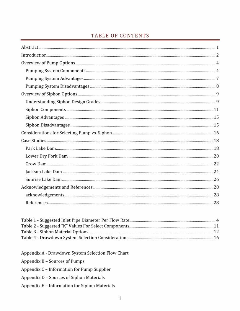
TABLEOFCONTENTS
Abstract.......................................................................................................................................................................................1
Introduction..............................................................................................................................................................................2
OverviewofPumpOptions.................................................................................................................................................4
PumpingSystemComponents......................................................................................................................................4
PumpingSystemAdvantages........................................................................................................................................7
PumpingSystemDisadvantages..................................................................................................................................8
OverviewofSiphonOptions..............................................................................................................................................9
UnderstandingSiphonDesignGrades.......................................................................................................................9
SiphonComponents........................................................................................................................................................11
SiphonAdvantages..........................................................................................................................................................15
SiphonDisadvantages....................................................................................................................................................15
ConsiderationsforSelectingPumpvs.Siphon.........................................................................................................16
CaseStudies.............................................................................................................................................................................18
ParkLakeDam...................................................................................................................................................................18
LowerDryForkDam......................................................................................................................................................20
CrowDam............................................................................................................................................................................22
JacksonLakeDam............................................................................................................................................................24
SunriseLakeDam.............................................................................................................................................................26
AcknowledgementsandReferences.............................................................................................................................28
acknowledgements..........................................................................................................................................................28
References...........................................................................................................................................................................28
Table1‐SuggestedInletPipeDiameterPerFlowRate.........................................................................................4 Table2‐Suggested“K”ValuesForSelectComponents.......................................................................................11 Table3‐SiphonMaterialOptions.................................................................................................................................12 Table4‐DrawdownSystemSelectionConsiderations........................................................................................16
AppendixA‐DrawdownSystemSelectionFlowChart
AppendixB–SourcesofPumps
AppendixC–InformationforPumpSupplier
AppendixD–SourcesofSiphonMaterials
AppendixE–InformationforSiphonMaterials


1
ABSTRACT
The Guideline for Use of Pumps and Siphons for Reservoir Drawdown provides the readerinformation todetermine thebestmethod toemploy for reservoirdrawdown.Bothpumpsandsiphons effectively remove water from reservoirs and can provide the necessary increasedcapacity in emergency situations. Each site and event has unique circumstances which willdetermine themethodbest suited.This guidebookoutlines aprocessusingbasichydraulic andlogistical considerations for determining the bestmethod for reservoir drawdown. Part of thisprocess includesoutlining important factors tobeused indecisionmaking.Key topics forbothpumpsandsiphonsareexploredindetail.
Where access to the dam is adequate, a pumping system could be considered. A pump cantransport water over dam crests at almost any lift height and can provide a large flow ratecapacityincreasewhensizedcorrectly.Largepumpscanbecumbersomeandsometimesrequirecontinual observation to prevent maintenance issues and damage. A power source must beidentifiedandbereliableatthedamsite.Withthepumpingoption,bothenergyandobservationcostsaresignificantfactorsforconsideration.
Siphonstypicallyrequirelessmaterialandequipmentallowingforuseinmoreremotelocationswithmoredifficultaccessandwhensetupproperly,canrequireminimaloversight.Siphonsarelimited by the height of lift from the reservoir to the crest of the dam. They also require careduringinitialsetuptoensureairtightnessandproperinletandoutletconditions.Itisofteneasiertosetupseveralsmallersiphonsratherthanasinglelargesystem.
Someimportantconsiderationswhendeterminingwhichmethodtouseare:
• Heightofliftoverdamcrest
• Depthofdrawdownrequired
• Dischargeflowraterequired
• Accessavailableatsiteandpowersourcesavailable
• Damembankmentstability
• Inletandoutletconditions,waterdepths,armoring,anddebris
• Amountofoperationandmaintenancetimeavailable
• Availabilityofsupportingequipmentandcost

2
INTRODUCTION
The purpose of this guide is to provide a resource to persons involved in the drawdown of areservoir.Reservoirdrawdowncanonlybeaccomplishedwhentheoutflowrate isgreater thantheinflowrate.Undernormaloperatingconditions,reservoirdrawdownisaccomplishedthroughtheuseoftheoutletworksandalsothroughtheuseofspillwaysdependingonthewaterlevelinthereservoir.Whathappenswhentheoutletworksareinoperable?Nothavingmeanstocontrolthereservoirlevelmaycreateariskysituationandmayplaceboththedamownersandpublicinjeopardy.
Alldamsshouldhaveaproperlydesignedemergencyspillwaytocontrolovertoppingandpreventembankment failure. However, even emergency spillways have a given capacity. When inflowratesexceedtheoutflowcapacityofadam,suchasduringthefailureofoutletworks,alternativedrawdownmethods are needed.Without amechanism to control outflows, the reservoir couldovertopthedamcrestresultingindamagestothedam,down‐gradientpropertiesandcouldplacethe general public at risk. This document explores the choice between pumping and siphoningalternativedrawdownmethods.
The guide is a reference for dam owners and operators, engineers, agencies and suppliers ofmaterials that may be used for temporary drawdown. Further, this guide will not make thedecision for you. Each situation is unique andwarrants adequate considerationonhowbest todrawdown the reservoir. This guide supplements the decisionmaking process by offering keypointstoconsiderduringthedecisionmakingprocess.ItcanalsobeausefultoolfordamownersdevelopinganEmergencyActionPlan(EAP).Temporarysolutionsarethefocusofthisguideandthedrawdownmethodsdescribedarenotintendedtobepermanent.
FIGURE1‐ TYPICALDAMCOMPONENTS

3
Itshouldbenotedthatinformationinthisguideisbasicinnature.Damownersareencouragedtocontact a professional engineer if the situation is complicated. Some situations or sites mayrequire additional analysis. Some factors that could warrant further investigation are, but notlimitedto:
Remotelocations, Largecrestwidth, Long‐termsolutionneeded, Specificand/orlargeoutflowraterequired,and Damstabilityissues.
Examplescenariosofwhenthisguidewouldbeutilized:
Emergencyrepair– In theeventanoutletworks is inoperableand theriskof significantinflowexists,apumporsiphoncouldbeusedtodrawdownthereservoirtoallowrepairoftheoutletworksandpreventovertoppingofthereservoir.Inanemergencysituation,thedamownershouldreferencetheEAP.Awell‐developedEAPshouldoffer:
o safedrawdownratesandmaximumdischargeratesforeachdam,o providethedamowner/operatorwithallnecessaryinformation,ando includeemergencydrawdownproceduresandmethods.
Standardmaintenance–Theuseofthedrawdownmethodsdescribedinthisguidearenot
limited to emergency situations. For example, if maintenance of dam structure requiresdrawingdownthereservoiratamoreexpeditedratethantheoutletstructureandspillwaycanprovide,thendrawdownmaybesupplementedusingapumporsiphon.
Sourceofwaterdelivery–Inlieuoftraditionaloutletworks,somedamshaveusedsiphonsorpumpsastheonlysourceofwaterdelivery.Forexample,ifadamhistoricallyhadissuessuchaspipinganderosionwithanexistingoutletworks,theownermayelecttoabandontheoutletworksforasiphon.

4
OVERVIEWOFPUMPOPTIONS
Pumpingwateroverthedamcresttodrawdownareservoircanbeatimelyandeffectivemethod.Propersizingoftheinletpipe,pump,airvent,andoutleterosionprotectionarecriticaltoensuredrawdownneedsaremetwithsuccess.This sectionreviews thebasic componentsofpumps tohelp thedamownerunderstandandselect thebestpumpingconfiguration for thesite.Often,apump supplier can assist the owner through this process. Thepump supplier should query thedamowneraboutsitespecificinformationtoassistinthesystemconfiguration.
Pumpsandtherequiredpartscomeinawiderangeoftypesandmanufacturers.Thebasiclayoutofapumpingsystemcangenerallybebrokendown into fivecomponents.Thecomponentsofatypicalpumpingsystemaretheinletpipe,pump,powersource,airvalvesandoutletpipe.
PUMPINGSYSTEMCOMPONENTS
Inlet Pipe: Selection of the pipe size and type will affect theperformance of the pumping system. A pipe diameterwith sufficientcross sectional area should be used to prevent excess friction andtransitionallosses.Whenflowvelocitiesexceedapproximately12feetpersecondtheseeffectscanhinderpumpingcapacity.Table1includesgeneral guidelines for the size of pipe required for a given flow,although it is important to rely on the pump supplier forrecommendations.Besurethatthepipebeingusedwillbecapableofwithstandingthepressuresexpected.
Thefollowingtableprovidesrule‐of‐thumbguidanceontheinletpipesizesrequiredperflowratetoavoidexcessivelossesfromwatervelocity.Apumpsupplierwillalsoofferguidancebasedonaparticularpumpmodel.
TABLE1‐SUGGESTEDINLETPIPEDIAMETERPERFLOWRATE
Flowupto(gpm)
Pipediameter(in)
300 4600 61100 81700 102500 12
Pump and Power Source: A common pump type used for pumping irrigation water is acentrifugalpump.Thistypeofpumphastwomaincomponents:animpellerattachedtoarotatingshaft,andastationarycasingorhousing(volute)enclosingtheimpeller.Theimpellerconsistsofanumberofbladesthatareusuallycurvedandarearrangedinaregularpatternaroundtheshaft.
Alsoconsidertheneedforaninletscreentopreventdebris
fromenteringthepumpand
causingdamage.

5
FIGURE2–TWOSUBMERSIBLEPUMPSPRIORTOINSTALLATION
Astheimpellerrotates,fluidismovedintothehousingthroughthecenterofthecasingandflowsradiallyoutward.
Severalconsiderationsareassociatedwiththistypeofmechanism.First,sometypeofpowersource must be available. Several differenttypes of pumps are currently available thatallow the pump to be run from differentenergysourcesincludingelectricityanddieselengines.Asecondconsiderationisavailabilityandtransportationofthepumpandassociatedequipment.
A person should be assigned to monitor thepumpthroughoutoperationevery3‐12hoursat a minimum. Some installations warrantcontinuousmonitoring.Consultwiththepump
supplier for operation and maintenancerecommendations.
The pump needs to be sized to pump the necessary calculated flow rate and overcome themaximum elevation difference between the dam crest and the reservoir. Pumpmanufacturerspublish pump curves showing pump performance against varying Total Dynamic Head (TDH).TDHisthesumofelevationandhydrauliclossesthatthepumpmustovercome.ThepumpcurvewillindicatetheflowrateapumpcangeneratewhenpushingagainstTDHvalues.ThelargestTDHvaluemay occurwhen the pump has been in operation for awhile and thewater level in thereservoirhaddroppedtoitslowestelevation.
It is important to understand that some pumped systemscould create a siphoning effect. An engineer or pumpsuppliermayhelpdetermineifasiphoneffectcouldindeedoccur. Provisions should bemade to avoid a siphon effectwith a pumped system because a siphon in this casemaydamagethepump.Installationofanairvacuumvalveoftheappropriatesizeattheappropriatelocationcouldbreakthewatersealandpreventasiphoneffect.
Pumpsmaybefairlylargeandbulkydependingonthesize.Atrailermayberequiredforthetransportofthepumpandassociatedequipment.Thepumpmayalsobemountedon a skid for easeofmobility. If the locationof the reservoir is not close to amaintainedroad,thenthatrestrictionmustbeadequatelyaddressed.
AnotherpumpconsiderationistheavailabilityofNetPositiveSuctionHead(NPSH).NPSHisthedifferenceinthetotalheadontheinletorsuctionsideofthepumpandtheliquidvaporpressureon the inside of the pump expressed as head. It can also be thought of as the total amount of
TopreventtheNPSHAfromreducingtoanunsafelevel,itmaybenecessaryto
relocatethepumpaswaterleveldrops.Also,theelevationofthereservoirshould
beprovidedtopumpsupplierssincehigh
elevationscancauseNPSHAreduction.

6
FIGURE3–A90BENDISDIRECTEDUPONTHEOUTLETPIPETODISSIPATEENGERGY
FIGURE4 ‐ VALVESINSTALLEDONAPIPE
suctionpressureavailabletothepump.EachpumpmanufacturedhasapublishedNPSHcurvetodetermine the amount of NPSH required (NPSHR) at aparticularflowrate.Whenpumpsoperateatlowflowratesand/or when adequate straight runs of piping are notprovidedupstreamofthepumpinlet,theamountofNPSHavailable (NPSHA) decreases. If the amount of NPSHAdrops below the NPSHR, the pump may experiencecavitation. Cavitation is a situation that results from theliquidpressurebeingreducedtothevaporpressureoftheliquid.Whentheliquidpressurereachesthevaporpressureinsideofthepump,theliquidboils.Overaperiodoftime,theimpactoftheairbubblesbreakingagainsttheinnercomponentsofthepumpwilldrasticallyshortenthelifeofthepumpimpeller,mechanicalseals,bearings,andothercomponents.
Whenconsideringthesizeandnumberofpumpsforyoursystem,factorinredundancytoaccountfortheriskofpumpdowntimeduetomaintenanceorfailure.
OutletPipe: It is important toensure that the outlet of thepipedoesnotcausedamagetothe downstream slope of thedam embankment. Scourand/or saturation of theembankment or toe can causeserious stability problems. Toensuredamstabilityproblemsare avoided, outletsshouldbe locatedwelldownstreamof thedamtoeand have adequate scour protection. Outletprotection measures will vary depending on damstability, downstream conditions, and the pumpingflowrate.
Combination Air Valves, Air Release Valves and AirVacuum Breaker Valves: Air in pipeline systems is asignificantconsideration.Airwillentertheinletifitistooclosetothewatersurfaceorifthewaterbeingpumpedisentrainedwithair.Airinthelinecollectsathighpointsinthe system and trapped air can reduce pipe capacity,increase wear on the pipe and reduce pump efficiency.Thecrestofthedamisoftenthehighpointinthesystemand warrants an air release valve if conditions suggestthis could be an issue. Air release valves should beattachedtoanyotherhighpoint(s)inthepipelinetoallowairtrappedinthepipetoescape.
Installtheoutletpipetoavoidisolatedhighpointsintheline.
Anindicatorofcavitationisthesoundofgravelbeingpumped.Ifyouhearthissound,IMMEDIATELYTURNOFFTHEPUMP.

7
The air release valve can be either an automatic air release valve or a less expensivemanualreleasevalue.Asthenameimplies,themanualvalverequiresmanualoperation.Theselectionofanautomaticversusmanualvalueisbasedonthedurationoftimethesiphonorpumpingsystemisinstalledandtheavailabilityofresourcestooperateamanualvalve.
A vacuum breaker valve is used in situations where vacuumprotection is amust orwhere column separation is predicted.Thevacuumbreakerismountedatcriticalpipelinehighpoints,andallowsforrapidinflowofatmosphericairtoreducevacuumconditions in piping systems. Without a vacuum breaker, apumping system could inadvertently create a siphon effect orsignificantlowpressureinthedischargeline.Theinstallationofa vacuum breaker at the high point will introduce air to thesystem to avoid a siphon effect such that the water flowingdownhill is free flow and not acting as a siphon. The risk tocreating an uncontrolled siphon effect on a pumped system isthattoomuchwatercouldbepulledthroughthepumpcausingincreasedvelocitiesandincreasingtheriskofcavitation.Further,avacuumbreakerreduceslowpressuresinthelineandpreventspipecollapseassociatedwithlowpressuresintheline.Apumpsupplierorengineermayopttodesignthepumpsystemtoexcludeavacuumbreakerandincludeasiphoneffect;however,thisanalysismustbecarefullyexaminedastoavoidcavitationinthesystemorpipecollapse.
A qualified professional engineer or pump suppliermay suggest critical locations in the pumpsystemtoavoidissueswithairentrainmentorairvacuums.
PUMPINGSYSTEMADVANTAGES
Theadvantagestoapumpdewateringsystemincludeeaseofinstallationandabilitytohandleahighdegreeof lift.Pumpsarerelativelyquicktosetupandaremanufacturedinmanydifferenttypesaswellassizes.Also,pumpsareabletodealwithalargeelevationlift,whichisimportantconsidering a siphon alternative may not be feasible when lifts greater than 15‐20 feet arerequired. Required lift refers to the vertical distance from the water surface elevation to thehighest point that the water may need to be pumped to in order to drawdown the reservoir.Normallythathighpointwouldbethetopoftheembankmentofthedam.Pumpscanbesizedtoprovided whatever lift is required. Pumps are capable of handling significant lift because thegreaterthelift,alargerpumporanintermediate“booster”pumpcanbeinstalledtoliftthewateroverthedamcrest.Pumpsareadvantageousinasituationwherethereservoirlevelsneedtobeloweredquicklywheretheliftexceeds15‐20feet.
Acombinationairvalveisanairreleasevalveandvacuumbreakervalveinonecomponent.
Columnseparationisaphenomenonthatcanoccurduringawater‐
hammerevent.Ifthepressureina
pipelinedropsrapidlytothevaporpressureoftheliquid,theliquid
vaporizesanda"bubble"ofvapor
formsinthepipeline.

8
PUMPINGSYSTEMDISADVANTAGES
Pumpsareoftenlargeandheavy,requiringatrailerfortransportationtoasite.Ifthedamsiteislocatedinaremotelocationwithrestrictedaccess,apumpmaynotbeaverygoodoption.Pumpsarealsocostlytorentatapriceofapproximately$150‐$350adayexcludingfreightandfuel.Notallpumpsizesarestockedbypumpsuppliersforshortnoticeuse.Thepumpsavailablemayhavetoo low of a pump capacity and may not be able to handle the amount of elevation changerequired.Apumpsuppliermayhavetoorderintheparticularsizeneededwhichmaytakeseveralweeks (pump suppliers are not a prevalent as pipe suppliers and travel distances can increasebecauseofthat).
Other disadvantages to pumping systems are that they require an energy source andmust bemonitoredduringtheperiodthattheyarepumping.However,differenttypesofpumpshavetheabilitytorunfromdifferentpowersources.Severalofthetypesofpowersourcesthatapumpmayrunoffof include:electricmotor,dieselengine,gasolineengine, tractorPTO,andhydraulic flowandpressure.Pumpsneed tobe regularlymaintainedandmonitoredduring theperiodof timethatthepumpisbeingoperated.Ifapumpweretocavitateorweretorundry,seriousdamagecouldoccurtothepump,reducingefficiencyorstoppingoperationaltogether.

9
OVERVIEWOFSIPHONOPTIONS
Siphons are an inverted u‐shaped pipe or closed conduit that are filled or primed to allowatmosphericpressuretoforcewaterfromareservoiroveranembankmentdamandouttheotherendofthepipe.Thepipeorconduitisdesignedtorunfullandunderapressuredifferential.Theinletofthepipeformsavacuumanddrawswaterupthroughthepipe,overadesignatedlift,anddischargesthewateratalocationbelowtheoriginalwaterlevel.Asealbetweenthewatersurfaceandthepipeinletandoutletkeepsairfromenteringthepipeandallowswatertoflowthroughthepipe, over the embankment to the location of the outlet. In some situations, a vacuum breakervalvemayberequiredonthedown‐gradientendofthesiphon.Aprofessionalengineercanadviseontheneedandlocationofavacuumbreakervalve.Siphonscaneffectivelydrawdownthelevelofthesurfaceinthereservoirandmovetheexcesswatertoaconvenientlocationdownstreamofthedamintheoutletchannelinsomesituations.
FIGURE5‐TYPICALSIPHONCOMPONENTS
UNDERSTANDINGSIPHONDESIGNGRADES
Thissectionreviewskeydesigncriteriatohelpthereaderunderstandifasiphonisappropriatefortheirspecificsite.Aseriesofequationsarepresentedtohelpthedamownerdetermineifthesiteelevationsandsiphonwillservedrawdownneeds.Aprofessionalengineercanalsoassistwiththecalculationsanddesign.
Thegreatestchallengeswithsiphondesignallrelatetotheelevationsof the siphon pipe. Most important are the dam crest elevation inrelation to minimum water surface elevation. If this difference inelevation is toogreat, thesiphonwillnotwork.Siphonoperation isbased on atmospheric pressure lifting the water up the siphon.Siphonoperationislimitedtotheelevationdifferencethatproduceswater vaporization. If the lift is too great, thewaterwill vaporize,whichresults intheinabilitytocreateasiphoneffectandmayevencausepipecollapse.
Ifthedamcrestistoohighcomparedtothesurfacewater
elevation,considerdigginga
temporarynotchinthedamcresttoreducerequiredlift.

10
1000'20
RWSRWSDCE
When deciding if a siphonwillwork for your site, themostimportantequationtounderstandistheMaximumSiphonLiftEquation. Todetermine if the elevations inthe systemare appropriate for siphondesign, the firstmeasurement that should be taken is the differencefrom the dam crest elevation (DCE) to the minimumreservoir water surface (RWS) elevation. Figure 5showsthelocationoftheRWSandDCE.Thisvaluecanbeusedtodetermineifasiphonishydraulicallyfeasibleat the site according to the Maximum Siphon LiftEquation.
Thisequationisbasedontheatmosphericpressureatsealevel.Notethatwatervaporpressuredecreaseswithincreasingelevation.Itisimportanttoconsiderthatthereservoirsurfaceelevationchanges as the siphondrawsdownwater. The equation should be reviewed for theworst casesituation,whichisthelowestreservoirwatersurfaceleveldesired.Asthewaterlevellowers,theverticaldistancefromthewaterleveltothetopoftheembankmentwillincrease.Ifthatdistanceincreases beyondwhat the siphon can lift, itwill stopworking, perhaps not drawing down thereservoirwaterlevelfarenough.Iftheleftsideoftheequationisgreaterthantherightsideoftheequation,thenasiphonwillnotworkforyoursite.
Ifthesitewillallowasiphon,anotherequationcanbeusedtodeterminethesiphonflowcapacity.Thiswillhelpyouestimatethesizeandnumberofsiphonsneeded.Thisequation,knownasthePredictedSiphonFlowrateEquation isavariationof theBernoulliEquationsimplified toaccountfortypicalsiphonapplicationsforcleanwater.Thisequationisonlyvalidfordamsitesthat:1)theelevationsatisfiestheMaximumLiftEquation,and2)avacuumbreakervalvedoesnotinterruptthesiphoneffectbetweenthereservoirwatersurfaceandtheoutfallwatersurface.
Intheseequations:
o Qisflowincubicfeetpersecond(cfs)iscalculatedfromtheequationabove,o Disthesiphonpipediameterininches,o Histheelevationdifferencefromtheoutlettothereservoirwatersurface(RWS),o fisthedimensionlessfrictionfactorthatiscalculatedfromtheequationabove,o nistheManning’snvalueforthepipematerialthatcanbefoundinmosthydraulic
referencebook,ando Listhetotallengthofpipe.
5.05.05.2 120438.0 DKDfLHDQ
33.0
2425
Dnf
FIGURE6 ‐ NOTCHINGTHECRESTOFADAMTOREDUCELIFTFORSIPHON
11
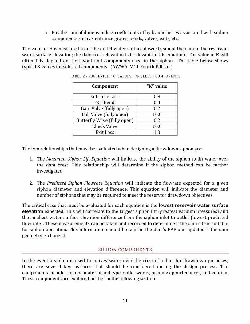
o Kisthesumofdimensionlesscoefficientsofhydrauliclossesassociatedwithsiphoncomponentssuchasentrancegrates,bends,valves,exits,etc.
ThevalueofHismeasuredfromtheoutletwatersurfacedownstreamofthedamtothereservoirwatersurfaceelevation;thedamcrestelevationisirrelevantinthisequation.ThevalueofKwillultimately depend on the layout and components used in the siphon. The table below showstypicalKvaluesforselectedcomponents.(AWWA,M11FourthEdition)
TABLE2‐SUGGESTED“K”VALUESFORSELECTCOMPONENTS
Component “K”value
EntranceLoss 0.845°Bend 0.3
GateValve(fullyopen) 0.2BallValve(fullyopen) 10.0
ButterflyValve(fullyopen) 0.2CheckValve 10.0ExitLoss 1.0
Thetworelationshipsthatmustbeevaluatedwhendesigningadrawdownsiphonare:
1. TheMaximumSiphonLiftEquationwill indicatetheabilityofthesiphontoliftwateroverthe dam crest. This relationship will determine if the siphon method can be furtherinvestigated.
2. The Predicted SiphonFlowrateEquation will indicate the flowrate expected for a givensiphon diameter and elevation difference. This equation will indicate the diameter andnumberofsiphonsthatmayberequiredtomeetthereservoirdrawdownobjectives.
Thecriticalcasethatmustbeevaluatedforeachequationisthelowestreservoirwatersurfaceelevationexpected.Thiswillcorrelatetothelargestsiphonlift(greatestvacuumpressures)andthesmallestwatersurfaceelevationdifference fromthesiphon inlet tooutlet(lowestpredictedflowrate).Thesemeasurementscanbetakenandrecordedtodetermineifthedamsiteissuitableforsiphonoperation.This informationshouldbekept in thedam’sEAPandupdated if thedamgeometryischanged.
SIPHONCOMPONENTS
In theeventa siphon isused to conveywaterover the crestof adam fordrawdownpurposes,there are several key features that should be considered during the design process. Thecomponentsincludethepipematerialandtype,outletworks,primingappurtenances,andventing.Thesecomponentsareexploredfurtherinthefollowingsection.

12
FIGURE7 ‐HDPEPIPEBEINGUNLOADED
PipeMaterials: Siphon pipematerials can have an effect onthe operation as well. Pipe materials vary in many differentways both structurally and hydraulically. It is especiallyimportant that the selected pipe can withstand the negativevacuumpressuresofasiphon.Pipematerialsuchasaluminumor thinwalled plastic pipe should only be usedwith cautionand only in applications with minimal lift. Local availabilitywill often be a determining factor in which material to use.Table 2 provides some basic information on pipe material
characteristics.Eachmaterialcantypicallybefoundinawiderangeofsizesthatwillaccommodatesiphonoperations.
The selection of a pipe material should consider whether or not there is a pipe, joints, andaccessories supplier located near or relatively close to the dam site. Access to the site for thetransportationofmaterialstothedamisalsoaconsideration.Howthepipeistobebroughtinorwhatthelocaldistributorhasavailablemaydeterminehowmanysiphonsaretobeusedandwhatsizeofpipewillbeused.Itmaybemoreeconomicalandtimelytousemultiplesmallerdiameterpipesratherthanalargediameterpipe.Pipesuppliersareanimportantsourceofinformationandguidancewhensettingupasiphon.
TABLE3‐SIPHONMATERIALOPTIONS
PipeMaterial ConsiderationsHDPE Veryflexible,whichcaneliminatetheneedforbendfittings.
Canbefusionweldedtogethertocreateaveryairtightsystem,butwelding can be expensive, time consuming and subject to theavailabilityofappropriateequipment.
Maynotbereadilyavailableinsomelocations. Pipeisbuoyantandwillfloatifmeasuresarenottakentoweighthepipedown.
Bendradiusofpipecanbeusedtoeliminatefittings.PVC Canbebell/spigotjointedforgoodseal.
Rigid pipe so bend fittings or the use of flexible couplersmay beneeded.
Verycommon,mostpipesupplierswillhaveaquantityinstock. Musthaveadequatewallthickness(Schedule40or80)towithstandvacuum pressures. Schedule 80 may be more appropriate at thecrestofthedamtowithstandgreatervacuumpressures.
Usuallytheleastexpensiveoptionduetoavailability.Steel Weldjointswouldbebestforairtightnessbuttimeconsumingand
maybeexpensive. Pipeiscapableofwithstandinglargepressuresdifferentials. Relativelyheavycreatingdifficultyintransportandsetup. Relativelyexpensive.
CMP Typically not a good choice because of difficulty obtaining an air

13
FIGURE9 ‐ OUTLETOFSIPHONWITHVALVES
PipeMaterial Considerationstightseal,hydrauliccapacity,andmoredifficulttosetup.
Could be a good choice to transport outlet water to betterdownstream location to reduce erosion and effect of damembankment.
AluminumPipe Oftenreadilyavailable. Pipecollapsingstrengthisminimalandshouldonlybeusedifliftisminimal.
Inlet:Theinletofasiphonmustbeconfiguredtopreventairfromenteringinthepipe.Ifthewaterlevel is within two feet of the inlet, air may beintroduced into thesystemwith thecreationofavortex. One solution used to address thiscondition isplacinga flatpieceofplywoodabovethe inlet to serve as an “anti‐vortex baffle”.Anotherwaytopreventavortexistothrottletheflow using the valve installed on the down‐gradientendofthesiphon.
Othersiphoninletconsiderationsincludebuoyancyanddebris.Ifthepipeisofbuoyantmaterial,thenprovisionsshouldbemadetosinkthepipe foradequatesubmergence.Options forsinkingthepipe includemetal collars around thepipeor installing rebar tie‐downs around thepipe.Adebrisgratemaybeneededtopreventlargedebrisfromenteringthepipe.Inthatcase,thedebrisrackmayprovidesufficientweighttocounterbuoyancyeffects.Anengineerorpipesuppliermayassistwithbuoyancycalculations.
Outlet:Inorderforthesiphontofunctionoptimally,theoutletshouldbesubmergedtoavoidairentrainment in the siphon. A plunge basinmay be an ideal place to locate the outlet ofthe siphon. The greater the depth of waterover the outlet, the less likelihood ofentrainingairinthepipe.Again,twofeetisagoodminimumdepthovertheendofthepipe.
If vandalism is a concern, it may beappropriatetoburytheentiredown‐gradientend of the siphon. An exposed pipe isvulnerabletodamageandadamagedpipehasthepotentialtosiphonwaterdownthefaceofa dam. The uncontrolled release of waterdown the dam face could create erosion ofembankmentanddamstabilityissues.
FIGURE8 ‐ INLETSCREENONSIPHONINTAKE
14
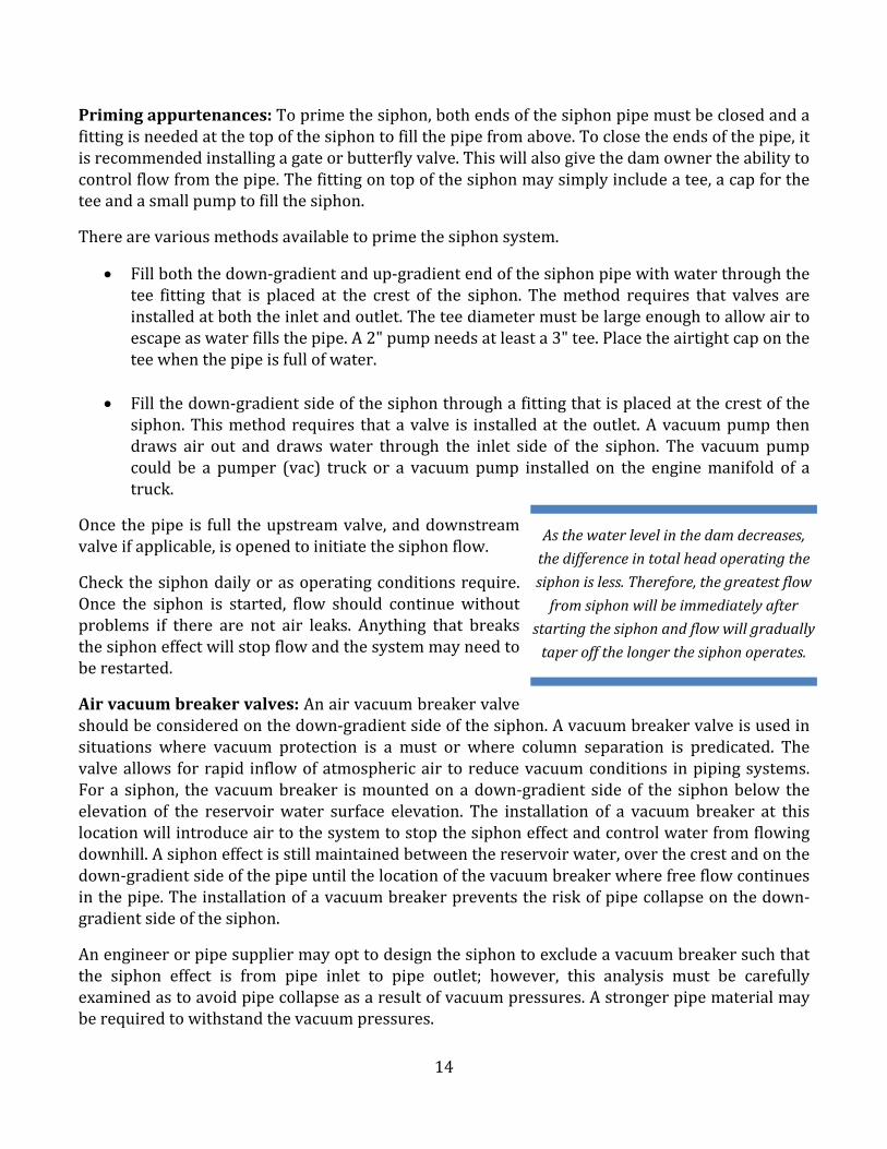
Primingappurtenances:Toprimethesiphon,bothendsofthesiphonpipemustbeclosedandafittingisneededatthetopofthesiphontofillthepipefromabove.Toclosetheendsofthepipe,itisrecommendedinstallingagateorbutterflyvalve.Thiswillalsogivethedamownertheabilitytocontrolflowfromthepipe.Thefittingontopofthesiphonmaysimplyincludeatee,acapfortheteeandasmallpumptofillthesiphon.
Therearevariousmethodsavailabletoprimethesiphonsystem.
Fillboththedown‐gradientandup‐gradientendofthesiphonpipewithwaterthroughthetee fitting that is placed at the crest of the siphon. Themethod requires that valves areinstalledatboththeinletandoutlet.Theteediametermustbelargeenoughtoallowairtoescapeaswaterfillsthepipe.A2"pumpneedsatleasta3"tee.Placetheairtightcapontheteewhenthepipeisfullofwater.
Fillthedown‐gradientsideofthesiphonthroughafittingthatisplacedatthecrestofthesiphon.Thismethodrequires thatavalve is installedat theoutlet.Avacuumpumpthendraws air out and drawswater through the inlet side of the siphon. The vacuum pumpcould be a pumper (vac) truck or a vacuumpump installed on the enginemanifold of atruck.
Oncethepipe is full theupstreamvalve,anddownstreamvalveifapplicable,isopenedtoinitiatethesiphonflow.
Checkthesiphondailyorasoperatingconditionsrequire.Once the siphon is started, flow should continuewithoutproblems if there are not air leaks. Anything that breaksthesiphoneffectwillstopflowandthesystemmayneedtoberestarted.
Airvacuumbreakervalves:Anairvacuumbreakervalveshouldbeconsideredonthedown‐gradientsideofthesiphon.Avacuumbreakervalveisusedinsituations where vacuum protection is a must or where column separation is predicated. Thevalveallowsforrapid inflowofatmosphericair toreducevacuumconditions inpipingsystems.Fora siphon, thevacuumbreaker ismountedonadown‐gradient sideof thesiphonbelow theelevation of the reservoirwater surface elevation. The installation of a vacuum breaker at thislocationwillintroduceairtothesystemtostopthesiphoneffectandcontrolwaterfromflowingdownhill.Asiphoneffectisstillmaintainedbetweenthereservoirwater,overthecrestandonthedown‐gradientsideofthepipeuntilthelocationofthevacuumbreakerwherefreeflowcontinuesinthepipe.Theinstallationofavacuumbreakerpreventstheriskofpipecollapseonthedown‐gradientsideofthesiphon.
Anengineerorpipesuppliermayopttodesignthesiphontoexcludeavacuumbreakersuchthatthe siphon effect is from pipe inlet to pipe outlet; however, this analysis must be carefullyexaminedastoavoidpipecollapseasaresultofvacuumpressures.Astrongerpipematerialmayberequiredtowithstandthevacuumpressures.
Asthewaterlevelinthedamdecreases,thedifferenceintotalheadoperatingthe
siphonisless.Therefore,thegreatestflow
fromsiphonwillbeimmediatelyafterstartingthesiphonandflowwillgradually
taperoffthelongerthesiphonoperates.

15
SIPHONADVANTAGES
Siphons are economical, easily built, and have proven a reliable means of water conveyance.Generally, thematerials are of greater availability than pumps and themaintenance associatedwith an actively running siphon can be lower than a pumping system. Aside from the initialconstruction of the siphon, fewer people may be needed to maintain the structure while it ismovingwater. Thematerials are both cost effective and reusable in the case of an emergencysituationrequiringreservoirdrawdownhappeningagaininthefuture.Finally,nopowersourceisrequiredtorunaproperlyinstalledsiphononceinoperation.
SIPHONDISADVANTAGES
Sitespecificgradelimitationsarethegreatestchallengetotheperformanceofasiphon.Siphonsare limitedtoabout20’of liftatmeansea levelandabout1 foot less foreach1,000 feetaboveMSL. “Lift” refers to theverticaldistance fromthewatersurfaceat the inletof thepipeandthehighestpointinthepipe.Ifthesiphonweretocarrywaterfromthesurfaceofareservoirupoveran embankment, and to an outlet on the downhill side of the embankment away from thereservoir,theliftwouldbetheverticaldistancefromthewater’ssurfaceattheinlettothetopoftheembankment.Also,dependingonyourstartingelevation, thesiphon’smaximumliftmaybecloser to 15’ as atmospheric pressure decreases. The elevations at your site may make itchallengingforasiphontoworkorbeattheupperlimitsoftheareathatasiphonmayeffectivelyperform.Othercommonchallengesstemfromissueswithpipematerialtype,pressureratingsandmaintainingairtightness.

16
CONSIDERATIONSFORSELECTINGPUMPVS.SIPHON
The choice between pumping and siphon methodswillbeuniquetoeachsiteandsituation.Onemethodmightbeappropriateforasiteduringoneoccurrencebut not the next. Several key pieces of informationshould be evaluated to decide which method toemploy.Thetablebelowprovidessomeinsighttothedifferences in the two methods. These criteria maydifferdependingonthesiteandsituation.
Sitecharacteristicsand logistical considerationsshouldbe the firstorder of business in the decision‐making process betweendrawdownmethods.Thisinformationwilldeterminewhetherornotsiphoningorpumpingmethodsare feasible. Ifonemethod isruledout, then the remaining method can be further investigated todeterminemorespecificcriteriaforthereservoirdrawdown.Onceasite has been determined to be suitable for both siphoning and
pumping, thenadditional considerations canbeevaluated to select anappropriatemethod.Thechartbelowdepictsanexampleofhowthisprocessmightbeappliedtoadrawdownsituation.
TABLE4‐DRAWDOWNSYSTEMSELECTIONCONSIDERATIONS
Consideration Pump Siphon Notes
Lift Nolimit,checkpumpcurves
Typicallylimitedtolessthan20’lift,seeSiphonOverview
Agoodunderstandingoftherequiredliftforyoursitewillhelpyoudetermineifasiphonisafeasibleoption.Iftherequiredliftistoogreat,itcanbeimmediatelydeterminedthatapumpistheonlyoption.Considercuttinganotchintheembankmenttoreduceoverallrequiredlifttoallowasiphontoworkcanbeanalternative.
Power Required(electrical,generator,etc.)
Onlyrequiredforinitialprimingofsiphon
Theavailabilityandcostofpowerisasignificantconsideration.Remembertoaccountforfuelconsumptionandfuelcostwhenevaluatingapumpoption.
Priming Notrequiredinmostsituations
Requiredtostartsiphon
Primingasiphon canbechallenging.Ifthesiphoneffectislost,thenthesiphonwillneedtobere‐primed.
LeadTime Varies,canbelongforlargepumps
Varies,usuallynotaslongaspumps
Dependingontheurgencyofthesituation,leadtimeforsuppliesmaybeacriticalfactor.Often,leadtimeonpumpsisassociatedwiththesizeandnumberofpumpsneeded.Leadtimeforsiphonmaterialsisbasedontheavailabilityofpipematerial.Consultwithapipesuppliertodeterminewhichpipesizesarestandardontheshelfpipesizes.Specialfittingsorspecial
DrawdownRatewillequaltheflowrateofthedrawdown
systemminustheinflowrate.
Considerthedownstreamcapacityandeffectsonthedamembankment,downstreamchannel,
infrastructure,andpublicsafety

17
Consideration Pump Siphon Notes
installationequipmentwillalsoaffectleadtime.
Monitoring Requiredevery3‐12hours,sometimesrequiredcontinuously
Onceperdayorlongerifsiteisisolated
Ifthepumpingorsiphonoperationisnotmonitoredconstantly,thereisariskofdamageorfailureoccurringonthepipeline(vandalism,seamfailure,gasketfailure,etc.)whichifundiscovered,couldleadtodamageonthedownstreamside(andevenpossiblytheupstreamside)ofthedamembankment.Theunintendedreleaseofwaterontoanunprotectedsoilembankmentcouldleadtoerosionanddamagetheembankment,whichcouldbecomeseriousquickly.
Capacity Varieswithpumpsizeandlift.Capacityisdeterminedfrompumpcurveandsiteconditions.
Varieswithpipesizeandliftrelatedtowatersurfaceelevation.CapacityisdeterminedbyPredictedSiphonFlowrateequationorenergyequation.
Thecapacityandconfigurationofthedewateringsystemmaybedependentontheavailabilityofmaterials.Inotherwords,severalsmallpumpsorsiphonsmaybeusedcomparedtoalargepumporsiphon.Determinethedrawdownratedesiredandresearchpumpandpipeoptionsbasedonthatinformation.
Access Musthavegoodvehicleaccessforlargepumps
Mayworkbestifaccesstositeislimited
Manyreservoirslocatedinmountainousterrainhavelimitedaccess.Ifthematerialcanonlybebroughtinbyhelicopterorhorseback,considertheweightandsizeofthematerial.
Cost Pipeandappurtenancesmaterialscostpluson‐goingcostsassociatedwithpumprentalfeesandfuel/power
Pipeandappurtenancesmaterialscost
Thecostofthesystemisoftenadriverindecidingwhichdrawdownmethodismostappropriate.Whendecidingonthemoreappropriatemethod,besuretoincludeup‐frontmaterialscost,on‐goingcostsassociatedwithrentalfeesandpowerandmonitoringcosts.Willthereservoirrequireroutinedewatering?Ifso,considerpurchasingpumpsorpipingmaterialstoservefutureneeds.
18
CASESTUDIES
Thesectionprovidesreal‐lifeexamples fromdamownerswithaneedtodrawdownareservoirusingapumporsiphon.Thecasestudiesoutlinethechallengesofthesituationandthedecisionsthedamownermadetodrawdownthereservoir.Thesecasestudiesexamine the findings fromeachoftheseexamples.
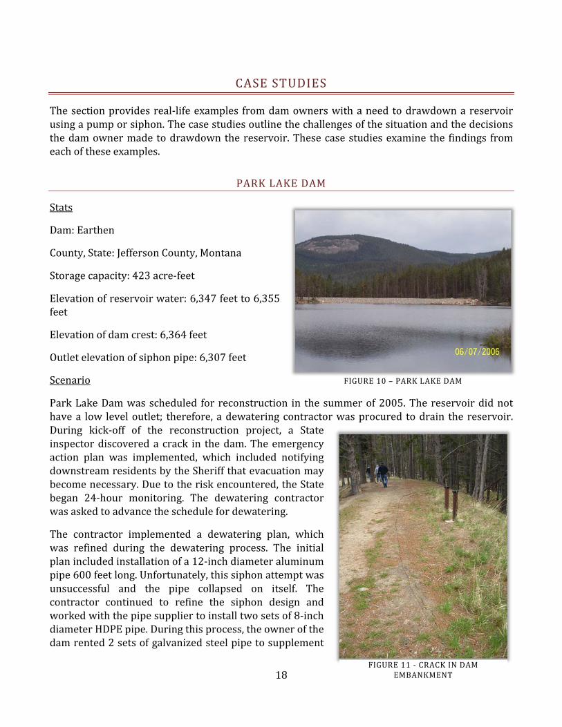
PARKLAKEDAM
Stats
Dam:Earthen
County,State:JeffersonCounty,Montana
Storagecapacity:423acre‐feet
Elevationofreservoirwater:6,347feetto6,355feet
Elevationofdamcrest:6,364feet
Outletelevationofsiphonpipe:6,307feet
Scenario
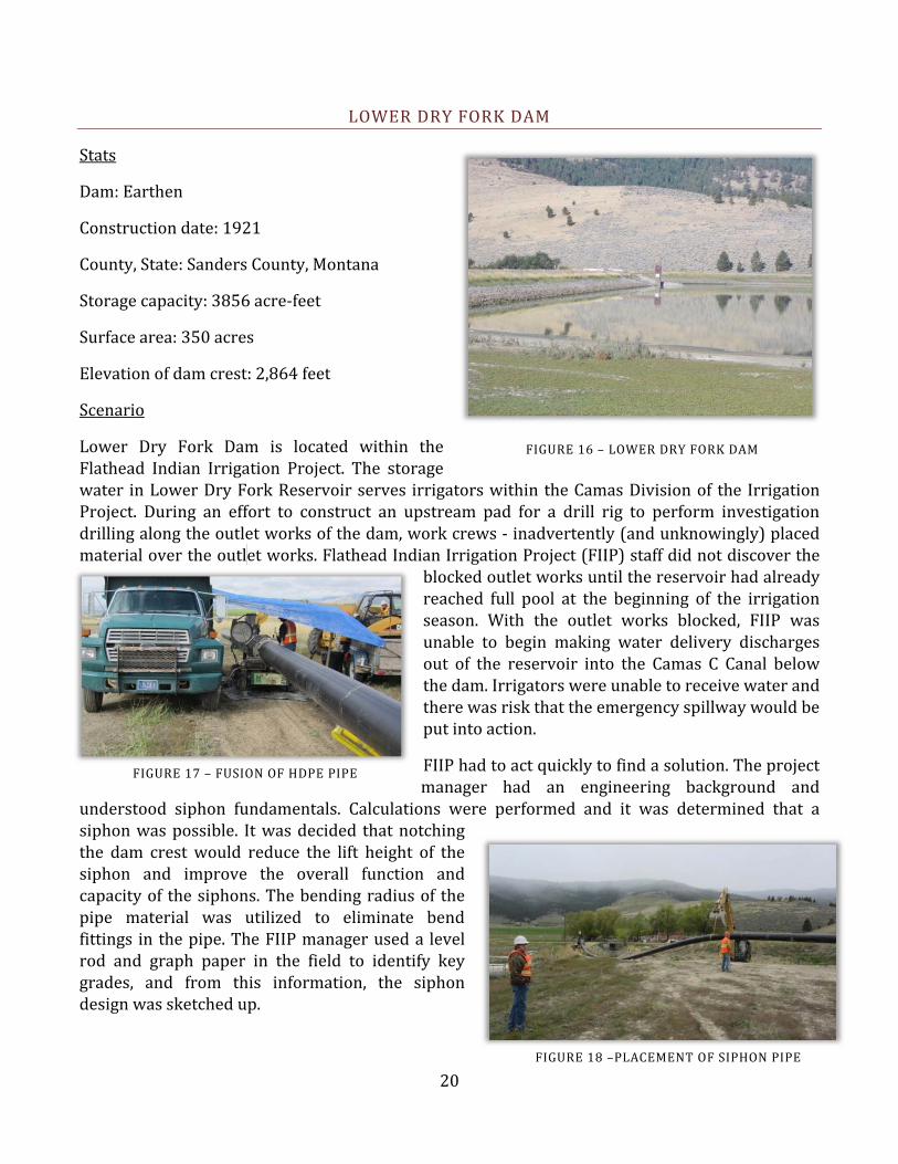
ParkLakeDamwasscheduled for reconstruction in thesummerof2005.Thereservoirdidnothavea low leveloutlet; therefore, adewateringcontractorwasprocured todrain the reservoir.During kick‐off of the reconstruction project, a Stateinspectordiscovereda crack in thedam.Theemergencyaction plan was implemented, which included notifyingdownstreamresidentsbytheSheriffthatevacuationmaybecomenecessary.Duetotheriskencountered,theStatebegan 24‐hour monitoring. The dewatering contractorwasaskedtoadvancetheschedulefordewatering.
The contractor implemented a dewatering plan, whichwas refined during the dewatering process. The initialplanincludedinstallationofa12‐inchdiameteraluminumpipe600feetlong.Unfortunately,thissiphonattemptwasunsuccessful and the pipe collapsed on itself. Thecontractor continued to refine the siphon design andworkedwiththepipesuppliertoinstalltwosetsof8‐inchdiameterHDPEpipe.Duringthisprocess,theownerofthedamrented2setsofgalvanizedsteelpipetosupplement
FIGURE10 – PARKLAKEDAM
FIGURE11‐CRACKINDAMEMBANKMENT

19
the dewatering system. Estimates from the owner suggest that each siphon was conveyingapproximately6.5cubicfeetpersecond.
Findings
In the end, the dewatering system included the four sets of 8‐inch diameter siphons operatingconcurrently for approximately two weeks. The unsuccessful attempt to siphon using thealuminum pipe was likely attributed to weak pipe strength associated with aluminum pipenotwithstandingthevacuumpressuresinthepipe.Reviewingtheelevationofthecrestofthedamat6,364andconsideringthat1’ofliftislostforevery1,000feetofelevationabovemeansealevel,thesesiphonscouldonlyliftwateratotalof13.6feet.Theresultisthatthesiphonwouldnotworkbelowareservoirsurfaceelevationof6350.4feet.
FIGURE14‐FOURSIPHONSINPARALLELOPERATION.THEPRIMINGFITTINGSARESHOWN.
FIGURE12
FIGURE15–AIRVALVES
FIGURE12–CRUSHEDALUMINUMPIPEFIGURE13– INSTALLATIONOFORIGINAL
ALUMINUMPIPE
20
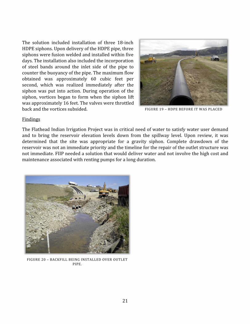
LOWERDRYFORKDAM
Stats
Dam:Earthen
Constructiondate:1921
County,State:SandersCounty,Montana
Storagecapacity:3856acre‐feet
Surfacearea:350acres
Elevationofdamcrest:2,864feet
Scenario
Lower Dry Fork Dam is located within theFlathead Indian Irrigation Project. The storagewater inLowerDryForkReservoirserves irrigatorswithin theCamasDivisionof the IrrigationProject. During an effort to construct an upstream pad for a drill rig to perform investigationdrillingalongtheoutletworksofthedam,workcrews‐inadvertently(andunknowingly)placedmaterialovertheoutl etworks.FlatheadIndianIrrigationProject(FIIP)staffdidnotdiscoverthe
blockedoutletworksuntilthereservoirhadalreadyreached full pool at the beginning of the irrigationseason. With the outlet works blocked, FIIP wasunable to begin making water delivery dischargesout of the reservoir into the Camas C Canal belowthedam.Irrigatorswereunabletoreceivewaterandtherewasriskthattheemergencyspillwaywouldbeputintoaction.
FIIPhadtoactquicklytofindasolution.Theprojectmanager had an engineering background and
understood siphon fundamentals. Calculations were performed and it was determined that asiphonwaspossible. Itwasdecided thatnotchingthe dam crestwould reduce the lift height of thesiphon and improve the overall function andcapacityof thesiphons.Thebendingradiusof thepipe material was utilized to eliminate bendfittings in thepipe.TheFIIPmanageruseda levelrod and graph paper in the field to identify keygrades, and from this information, the siphondesignwassketchedup.
FIGURE16 – LOWERDRYFORKDAM
FIGURE17–FUSIONOFHDPEPIPE
FIGURE18–PLACEMENTOFSIPHONPIPE
21
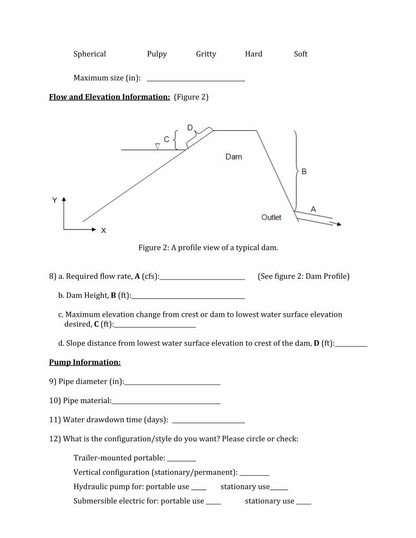
The solution included installation of three 18‐inchHDPEsiphons.UpondeliveryoftheHDPEpipe,threesiphonswerefusionweldedandinstalledwithinfivedays.Theinstallationalsoincludedtheincorporationof steel bands around the inlet side of the pipe tocounterthebuoyancyofthepipe.Themaximumflowobtained was approximately 60 cubic feet persecond, which was realized immediately after thesiphonwasput into action.During operation of thesiphon, vortices began to formwhen the siphon liftwasapproximately16feet.Thevalveswerethrottledbackandthevorticessubsided.
Findings
TheFlatheadIndianIrrigationProjectwasincriticalneedofwatertosatisfywateruserdemandand to bring the reservoir elevation levels down from the spillway level. Upon review, it wasdetermined that the site was appropriate for a gravity siphon. Complete drawdown of thereservoirwasnotanimmediatepriorityandthetimelinefortherepairoftheoutletstructurewasnotimmediate.FIIPneededasolutionthatwoulddeliverwaterandnotinvolvethehighcostandmaintenanceassociatedwithrentingpumpsforalongduration.
FIGURE19 – HDPEBEFOREITWASPLACED
FIGURE20–BACKFILLBEINGINSTALLEDOVEROUTLETPIPE.

22
CROWDAM
Stats
Dam:Earthen
County,State:LakeCounty,Montana
Storagecapacity:10,350acre‐feet (temporarilyrestricted to 3,500 acre‐feet due to need forspillwayrepairs)
Elevationofreservoirwater:2,867feet
Elevationofdamcrest:2,875feet
Scenario
CrowDam,locatedintheSouthDivisionoftheFlatheadIndianIrrigationProject(FIIP),provideswater to irrigators in theMoiseValley area of theProject. The outletworksof the damwas indisrepair. The outlet works consist of two cylinder gates. One cylinder gate had experienced
failure of both operating/lift stems and hadslammed shut earlier during operationaldischarges.Itwasdamagedandnolongeroperable.The backup cylinder gate was also exhibitingsymptomsofbeingdamagedandimmediateaccesstotheoutletworksgateshaftwasneededtoinspectand repair the backup gate. The mandatoryinstream flow of 21 cubic feet per second in thedownstreamcreekneededtobemaintainedduringthedewatering, inspection,andrepairoftheoutletworksgates.
TheFIIPmanagerinspectedthesiteanddeterminedthat grade limitations would rule out a siphon. Atthat point, pump suppliers were contacted tocoordinate sizing and delivery of pumps. Twodifferent suppliers offered two different pumpingplans and related costs. One pump suppliersuggestedskidmountedsuctionpumpswithdieselmotors. One pump supplier suggested submersiblepumpsconnectedtoagenerator.FIIPpreferredthesubmersible pumps due to expected fluctuatingwaterlevelsinthereservoir(expectedtoexceed25feet in elevation over a 7 day period). There was
FIGURE21– DISCHARGEPIPERUNNINGDOWNCROWDAMEMBANKMENT
FIGURE22‐SUBMERSIBLEPUMPSANDFLOATATION
FIGURE23–DIESELGENERATORS

23
concern that the intake lines for the skid mounted suction pumps would be too short for thefluctuatingwaterlevels.
In the end, six 8‐inch submersible pumps operated for aweek at a total cost of approximately$70,000. This price included the cost of the six submersible electric pumps, two diesel enginegenerators, HDPE piping from pumps to the downstream outlet channel (including fusion), allvalves and fittings, and allmobilization, assembly, anddemobilization. Theprice also includedcostsforprovidingtwobackuppumpsandonebackupgenerator.
Findings
Site constraints would not allow a siphon tofunction and left FIIP with pumping as theironly option. Two different pump rentalcompanies offered different pumping plansand related costs. Due to in‐stream flowrequirements, FIIP opted to go with thepumping plan that ensured continuous flowwithout requiring shut‐down tomove suctionlinesduetofluctuatingwaterlevels.Itwasalsothelessexpensiveoption.
FIGURE24– PUMPDISCHARGELINE

24
JACKSONLAKEDAM
Stats
Dam:Earthen
Yearconstructed:1936
County, State: Meagher County,Montana
Storagecapacity:490acrefeet(max.)
Reservoirsurfacearea:36acres
Damheight:33feet
Elevationofdamcrest:5,181feet
Elevationofreservoirlevel:5,170feet
Scenario
Throughwater storage in Jackson Lake, Jackson Lake Dam supplies irrigation water to a localranch. During the summer of 1999, the gate stem sheared off leaving the gate in the closedposition.Thespillwaydidhavecapacitytopassstormeventssodangertothedamembankmentdue to overtopping was not a concern. The damages to the gate stem, however, jeopardizeddeliveryofirrigationwater.
Inordertomaintainirrigationreleases,asiphonwasinstalledoverthetopofthedamusing80psiPVCpipe.Soonafter thesiphonwasprimed, thesiphoncollapsed likelydue topipematerial thatcouldnotwithstandthevacuumpressuresinthepipe.Anothersiphonwasinstalledusingstrongerpipematerial(120psiPVCpipe).Averticalslidegatewas installedat thedownstreamendof thesiphoninthestillingbasin.
The siphon served the needs of the irrigatorsthroughthegrowingseason.InSeptemberofthatsameyear,vandalsopenedtheslidegateandthesiphon flowwas lost. The ownerworked to re‐
primethesiphonandthesiphoncollapsedmidwaydownthedownstreamfaceofthedam.Theowneroptedtowaituntilthespringtodrawdownthereservoirtofixthegatestem.
FIGURE25– JACKSONLAKEDAM
FIGURE26– COLLAPSEDPVCPIPE

25
Findings
Reviewingtheelevationofthecrestofthedamat5,181andconsideringthat1’of lift is lostforevery1,000feetofelevationabovemeansealevel,thissiphoncouldonlytheoreticallyliftwateratotalof13.6feet.Theresultisthatthesiphonwouldnotworkbelowareservoirsurfaceelevationof5166.2inbestcaseconditionswithoutriskofwatervaporization.Asthesiphondrewthewatersurfaceleveldown,thevacuumpressuresbecamegreaterandgreater.Itappearsthatthe80psiPVCpipewasnotstrongenoughtowithstandthe initialvacuumpressuresandthatthe120psiPVCpipeonlycouldwithstandvacuumpressurestoacertainpoint.Itisspeculatedthatthewatersurfaceelevationwastoolowwhentheownertriedtorestartthesiphonandvacuumpressurescollapsedthepipe.

26
SUNRISELAKEDAM
Stats
Dam:SunriseLakeDam
County,State:ApacheCounty,Arizona
Owner:WhiteMountainApacheTribe
Maxsurfacearea:900acres
Elevationofreservoirwater:9,200feet
Scenario
SunriseLakewas createdby constructionof SunriseLakeDam, anearth‐fill embankment. Thehigh‐altitude lake is used as a recreational fishery. The original outlet through the dam wasflawedandhasnotoperatedsincethedamwasconstructed.Likewise,nowaterhaspassedoverthespillwaybecausewaterdrainingthroughaporouslayerofvolcanicrockonthenorthsideofthe reservoir preventswater from rising to the spillway elevation. Withnodischargeofwaterfromthereservoir,allorganicmatterandothernutrientsenteringthereservoiraccumulateinthedeeper parts of Sunrise Lake where they eventually cause anaerobic conditions and biologicoxygendemandthatdepletesoxygenconcentrationsintheaerobicpartsofthelake.
Theprocessofeutrophicationtookplaceoverdecadesduetothecoldwatertemperatureinthelake, but eventually conditions became adverse to the sport trout fishery in the reservoir. TheWhite Mountain Apache Tribe obtained the services of a professional engineer to review theproblemandrecommendasolution.Afterhiringafisherybiologisttoconductverticalprofilesofdissolved oxygen and temperature, to collect water samples from the vertical profiles and toprepareabathymetricmap;asiphonaccompaniedbyapipelinefromasourceoffreshwaterwasrecommendedtorestorethewaterinthereservoirtogoodconditionsforaquatichabitat.
Thesiphonwasdesignedtodrawwaterfromthedeepestpartofthereservoirwiththeintentthatit would remove nutrients that were pooled in the bottom of the lake. A three‐mile 10‐inchpipelinewasdesigned todivert freshwater fromBeckerCreek in order toprovide freshwaterinflow to Sunrise Lake to replace eutrophicwater siphoned out of the lake. An issuewith thesiphon design was the ability to prime the siphon using a vacuum pump due to the lowatmospheric pressure at 9,200 feet. This problem was solved by installing the siphon at anelevationbelowthetopofthedamwhereenoughvacuumcouldbegeneratedtoprimethesiphon.Anumberofissuesrelatedtoconstructionofthesiphonwereavoidedbyconstructingthesiphoninthewinter,assemblingitontheiceonSunriseLake,thencuttingthroughtheiceandloweringthe siphon into position. The time and cost for the diversion of fresh water to the lake wasminimizedbyutilizing10‐inchportablealuminumpipetoconveywaterfromthediversiontothelake,adistanceofthreemiles.
FIGURE27‐ SUNRISELAKE

27
Whenthesiphonwasputintooperation,anaerobicgraywaterwasdischargedfromthebottomofthereservoir.Removalofthenutrient‐ladenwaterandreplacementofitwithfreshwaterduringthewintermonths resulted in a tremendous improvement in dissolved oxygen throughout thereservoirbythefollowingsummer.Thetemporaryoperationofthesiphonandportablepipelineforfreshwaterresultedingoodconditionsinthereservoirforthenextthreedecades.
Findings
Thissiteofferedchallengesduetoelevation limitationsandlowatmosphericpressureathigherelevations.Thesolutionincludedreducingtheliftofthesiphonbynotchingthedamcrestatthesiphoncrossing.Asiphonwasagoodsolutiontomeettheobjectivestorestoretheaquatichealthofthislake.

28
ACKNOWLEDGEMENTSANDREFERENCES
ACKNOWLEDGEMENTS
This Guideline was prepared on behalf of funding from the Federal Emergency ManagementAgencythroughtheNationalDamSafetyActAssistancetoStates.WewouldliketoacknowledgetheDepartmentofNaturalResourceConservationDamSafetyProgramandMicheleLemieuxfortheir involvementandguidanceon thepreparationof thisdocument.Also,acknowledgement isgiventoGordonWindoftheFlatheadIndianIrrigationProjectforhishandsonknowledgeandsitetouroftheLowerDryForkReservor.Lastly,acknowledgementismadetobothGodwin(Xylem)PumpsandCrisafulliPumpsforinsightonthispaper.
REFERENCES
Munson,Young,Okiishi,FundamentalsofFluidMechanics,3ded.,JohnWiley&Sons,Inc.
ScottBryant,PEandDouglasJewell,PE,“AnalysisofSiphonLakeDrainPerformanceforaSmallEarthenDam”,AssociationofStateDamSafetyOfficials1996ConferenceProceedings
GordonWind(ManagerofFlatheadIndianIrrigationProject),conversationwithMollySkorpik,September7,2012
MicheleLemieux(DamSafetyProgramManager),conversationswithMollySkorpikJune–September2012
AQuickGuidetoSiphons,WatershedNews.10/2004

Appendix A ‐ Drawdown System Selection Flow Chart

No
No No
Yes
Yes No
Yes
No
Yes
Yes
No
No
Yes
Yes
Do the site elevations satisfy the
Maximum Lift Equation1?
Is there road access to the
site?
Use a pumping system.
Is there
power at the site?
Can provisions be made to get
large pumps into the site?
Use a siphon system.
Is staff time available to
monitor pump on a frequent / constant basis?
Can provisions be made to get
power for pumps to the site
(generator, power lines, diesel or
tractor)?
Is the drawdown
system a long -term solution?
Check cost and availability of equipment and
materials for both siphon and pumping options. Cost and availability will be significant determining
factors.
DrawdownSystemSelectionFlowChart
Note: 1. Reference Siphon Overview Design Grade Considerations for Maximum Lift Equation. 2. Every site is unique. This Chart is a starting guideline. Your situation may warrant a different solution.

Appendix B – Sources of Pumps

SourcesofPumpsinMontanaandSurroundingAreasThefollowingpumpsuppliersmayofferpumprentalsforreservoirdrawdown.Thelistisnot all inclusive and is not meant to preclude other pump suppliers not listed in thisdocument.PumpsuppliersserveareasoutsideoftheCitieslistedbelow.ForareasoutsideofMontana,researchpumpsupplierson‐line.
Billings,MT:ChampionCharterSales&Service2549EnterpriseAve.Billings,MT59102406‐655‐7828RainforRent1111MonadRoadBillings,MT59101406‐259‐7216WaterworksIndustries465MooreLaneBillings,MT59107www.waterworksind.comCharleyStiles,SalesBozeman,MT:RainforRent(pumprental)1111MonadRoadBillings,MT59101(406)259‐7216Fax:(406)259‐7251Dickinson,ND:RainforRent819ImplementDriveDickinson,ND58601(701)225‐7117Glendive,MT:SRSCrisafulli,Inc.1610CrisafulliDriveP.O.Box1051Glendive,MT59330Phone:800‐442‐7867Or406‐365‐3393
Helena,MT:GodwinPumps3860HelbergDriveHelena,MT59602Phone:406‐495‐1335AndyFitzhughIdahoFalls,ID:RainforRent3615RirieHighwayIdahoFalls,ID83401(208)‐522‐4500Fax:(208)522‐4511Windsor,CA:WaterworksIndustriesInc.(pumps)930ShilohRd.,Bldg.38,SuiteDWindsor,CA95492(707)837‐[email protected]: Other:

Appendix C – Information for Pump Supplier

InformationforPumpSupplierThe following information may be requested by pump suppliers. Use this worksheet togatherdatathatmayprovebeneficialtoapumpsupplier. GeneralSiteInformation:(Figure1)
Figure1:Aplanviewofadam.‘A’representsthedistancefromthereservoirwater’sedge
tothedischargelocationlocateddowngradientofthedam.1)Materialtobepumped: 2)Horizontaldistancefromreservoirtothedischargelocationinfeet,A(seefigure1:DamPlan):
3)Anydebrisinthewater?Ifso,describe(sizeinfeet).4)Anyinformationaboutanexistingpowersource:
5)Location&Access:
6)Descriptionofthesystemandsituation,picturesifnecessary:
7)Anysolidsinthewater?
Circleorcheckallthatapply:
Z
X
Dam
Cre
st
Reservoir
Spherical Pulpy Gritty Hard Soft
Maximumsize(in):
FlowandElevationInformation:(Figure2)
Figure2:Aprofileviewofatypicaldam.
8)a.Requiredflowrate,A(cfs): (Seefigure2:DamProfile)b.DamHeight,B(ft): c.Maximumelevationchangefromcrestordamtolowestwatersurfaceelevationdesired,C(ft):
d.Slopedistancefromlowestwatersurfaceelevationtocrestofthedam,D(ft):
PumpInformation:9)Pipediameter(in): 10)Pipematerial: 11)Waterdrawdowntime(days): 12)Whatistheconfiguration/styledoyouwant?Pleasecircleorcheck:
Trailer‐mountedportable:
Verticalconfiguration(stationary/permanent):
Hydraulicpumpfor:portableuse_____ stationaryuse______
Submersibleelectricfor:portableuse_____ stationaryuse_____
Y
X

13)Frequencyofpumpuse(checkone):_____Continuous _____Intermittent

Appendix D – Sources of Siphon Materials

SourcesofSiphonSuppliesinMontanaandSurroundingAreasThe following pipe suppliers may offer pipe materials for reservoir drawdown using asiphon.The list isnotall inclusiveand isnotmeant toprecludeotherpipesuppliersnotlistedinthisdocument.ForareasoutsideofMontana,researchsupplierson‐line.Belgrade,MT:NorthwestPipeFittingsInc.360FlossFlatsRoadBelgrade,MT59714406‐388‐2093Fax406‐388‐2093HDSupplyWaterworksLtd5240JackrabbitLaneBelgrade,MT59714‐90611‐406‐388‐5980HDFowlerCo.401EMainStBelgrade,MT597141‐406‐388‐1169Billings,MT:Ferguson1734LampmanDr.Billings,MT59102(406)655‐0010Utilities1723LampmanDr.Billings,MT59102(406)252‐0528NorthwestIndustrialSupply18192ndAvenueNorthBillings,MT59107406‐248‐1151Fax406‐252‐8835
Billings,MT(cont’d):NorthwestPipeFittingsInc.33South8thStreetWestBillings,MT59103406‐252‐0142Fax406‐248‐8072Bozeman,MT:Ferguson188PronghornTrailBozeman,MT59718(406)587‐8855AndersonPrecast&SupplyInc.80EValleyCenterRdBozeman,MT597181‐406‐586‐5087Butte,MT:NorthwestPipeFittingsInc.1901MeadowlarkButte,MT59701406‐494‐2120Fax406‐494‐3767Gillette,WY:Utilities1209EnergySt.Gillette,WY82716(307)682‐0748

GreatFalls,MT:Ferguson905RiverDr.SGreatFalls,MT59405(406)761‐8957NorthwestPipeFittingsInc.40417thAvenueN.E.GreatFalls,MT59404406‐727‐9843Fax406‐454‐1743Helena,MT:ContechConstructionProductsPOBox5478Helena,MT59604406‐442‐1012www.contech‐cpi.comDennisDirksKalispell,MT:Ferguson2435USHwy2EKalispell,MT59901(406)756‐7630Waterworks–Water&Sewer1093RoseCrossingDr.Kalispell,MT59901(406)755‐9242NorthwestPipeFittingsInc.1780Highway35Kalispell,MT406‐752‐6562Fax406‐752‐6553HDSupply1093RoseCrossingDr.Kalispell,MT59714406‐755‐9242
Missoula,MT:Ferguson3843BrooksSt.Missoula,MT59804(406)251‐4341Waterworks‐Water&Sewer(HDSupply)7372InterstatePIMissoula,MT59808(406)728‐7336GeorgeWhittaker,MTDistrictManagerMichaelRichards,ProductSpecialistNorthwestIndustrialSupply2304WestBroadwayMissoula,MT59802406‐543‐2982Fax406‐543‐1982Offersfullservicesiphonset‐up:GodwinPumps3860HelbergDriveHelena,MT59602Phone:406‐495‐1335AndyFitzhughOther: Other:
PossiblelistofEquipmentforPVCsiphon:
PlainendPVCpipe,schedule80,damcrestlength PlainendPVCpipe,schedule40,damembankmentslopelengths Rubbersleeveconnectors Flatbandclamps Two22.5degreeelbows One90degreeelbow Twovalves Trashguardforinlet,ifneeded 3”teetapwithanairtightplug Pumpandhosetofillthepipewithwater Trailertohaulequipment

Appendix E – Information for Siphon Materials

1000'20
RWSRWSDCE
InformationforSiphon/PipeDesignerorSupplierThe following information may be useful when ordering siphon supplies and/or whendecidingifasiphonisfeasible.Usethisworksheettogatherdatathatmayprovebeneficialwhenmakingthesedecisions.MaximumSiphonLiftEquation:
DamCrestElevation(DCE)= ReservoirWaterSurfaceElevation(RWS)= GeneralSiteInformation:1)Horizontaldistancefromreservoirtothedischargelocationinfeet: 2)DischargeChannelType(chooseone): Stream Ditch3)Anydebrisinthewater?Ifso,describe(sizeinfeet).4)Location&Access:
5)NearestTown:
6)Descriptionofthesystemandsituation,picturesifnecessary:
7)Anysolidsinthewater?
Circleorcheckallthatapply:
Spherical Pulpy Gritty Hard Soft
Maximumsize(in):
MaximumSiphonLiftEquation:FlowandElevationInformation:(Figure1)

Figure1:Aprofileviewofatypicaldamwithsimplesiphon.
8)a.Requiredflowrate,(cfs): (keepinmindmultiplesiphons
areofteneasiertooperatethanasinglelargesiphon)b.MaximumLiftHeight,A(ft): (Seefigure1:DamProfile)c.DamCrestWidth,C(ft): (Seefigure1:DamProfile)d.DamFaceSlopeLength,L(ft): (Seefigure1:DamProfile)e.DamHeight,D(ft): (Seefigure1:DamProfile)f.PredictedSiphonFlowRateEquation:(seetext)
Q(cfs)
H=D‐A(ft)L=totallengthofpipeordered(ft)
K(seetext)D=pipediameter(in)
N=Manning’sncoefficient(seepipesupplierinfo)
PipeMaterialInformation:9)Pipediameter(in): 10)Pipematerial: 11)Waterdrawdowntime(days):
Y
X
5.05.05.2 120438.0 DKDfLHDQ
33.0
2425
Dnf

12)NegativeInternalPressureCapacity(psiorft): 13)AllowableBendRadius(ft): 14)ValveFittingConnectionConfiguration:

3011 Palmer Street | Missoula, MT 59808 | 406.542.8880
www.m-m.net


![Computing Minimal Siphons in Petri Net Models of Resource ...ceur-ws.org/Vol-1160/paper18.pdf · many of the published work relies on minimal siphons for this [5–10]. A minimal](https://img.dokumen.tips/doc/110x75/5e9302061269af1096002889/computing-minimal-siphons-in-petri-net-models-of-resource-ceur-wsorgvol-1160.jpg)