Embed Size (px)
Citation preview
Final Aliso Canyon RCA:SS‐25A Wellsite Tubulars Handling Protocol
Prepared For:
RCA SS‐25: CPUC, DOGGR, SoCalGas
2600 Network Boulevard, Suite 550
Frisco, Texas 75034
+1 972‐712‐8407 (phone) +1 972‐712‐8408 (fax)
16285 Park Ten Place, Suite 600
Houston, Texas 77084
1‐800‐319‐2940 (toll free) +1 281‐206‐2000 (phone)
+1 281‐206‐2005 (fax)
www.blade‐energy.com
Purpose: Protocol for handling the tubulars and wellhead sections that are extracted from the SS‐25A well.
Version: 003
Date: 09‐May‐17
Project Number: SCG‐16‐001
© 2000‐2017 Blade Energy Partners
Blade Energy Partners Limited, and its affiliates (‘Blade’) provide our services subject to our General Terms and Conditions (‘GTC’) in effect at time of service, unless a GTC provision is expressly superseded in a separate agreement made with Blade. Blade’s work product is based on information sources which we believe to be reliable, including information that was publicly available and that was provided by our client; but Blade does not guarantee the accuracy or completeness of the information provided. All statements are the opinions of Blade based on generally-accepted and reasonable practices in the industry. Our clients remain fully responsible for all clients’ decisions, actions and omissions, whether based upon Blade’s work product or not; and Blade’s liability solely extends to the cost of its work product.

AC-RCA – Wellsite Tubulars Handling Protocol, SS-25A
AC-RCA SS25A Tubulars Handling Protocol Rev 003, 09-May-17.docx 2 of 46
Version Record
Version
No.
Issue
Date
Issued As /
Nature of Revision Author Checked By Project
000 11-Apr, 2017 Final WSW RLR RMK
001 29-Apr, 2017 Revised Final WSW/RLR RLR RMK
002 05-May, 2017 Revised Final WSW/RLR RLR RMK
003 09-May, 2017 Revised Final RLR RMK RMK
Revision History
Revision Date Description of Change
001 29-Apr, 2017 Clarifications around handling completion components, various corrections
002 05-May, 2107 Added comments from SCG to Sections 1 and 4, changed Sentinel 747 to Sentinel 909
003 09-May, 2017 Updated Section 1 to clarify Blade’s authority.

AC-RCA – Wellsite Tubulars Handling Protocol, SS-25A
AC-RCA SS25A Tubulars Handling Protocol Rev 003, 09-May-17.docx 3 of 46
Table of Contents 1 Introduction ........................................................................................................................... 4
2 Process Overview ................................................................................................................. 5
3 Wellhead Handling Procedures ............................................................................................. 6
4 Tubing Handling Procedures ................................................................................................. 8
5 Appendix ............................................................................................................................. 14
5.1 Visual Inspection Procedures ...................................................................................... 15
5.2 Cleaning and Corrosion Protection Procedures .......................................................... 18
5.3 Evidence Data Sheet & Chain of Custody ................................................................... 19
5.4 Tubular Performance Data .......................................................................................... 25
5.5 Extraction Documentation Forms ................................................................................ 27
5.6 Tectyl 506 Corrosion Inhibitor Product Information ..................................................... 32
5.7 Sentinel 909 Cleaning Product Information ................................................................. 34
5.8 Tectyl 846 Class 1 Corrosion Inhibitor Product Information ........................................ 42
5.9 Volatile Corrosion Inhibitor (VCI) Product Information ................................................ 44

AC-RCA – Wellsite Tubulars Handling Protocol, SS-25A
AC-RCA SS25A Tubulars Handling Protocol Rev 003, 09-May-17.docx 4 of 46
1 Introduction
This document describes the steps and procedures for handling the wellhead and tubing that will be extracted from the SS-25A well as part of the SS-25 Root Cause Analysis (RCA) work. The tubing that will be extracted consists of the following:
3-1/2" 9.3 ppf N80 with API EUE connections - 343 ft or 11 joints.
5-1/2" 20.0 ppf N80 with API LTC connections - 7,794 ft or 202 joints
2-7/8" 6.4 ppf N80 with API 8RD connection - 31 ft or 1 joint
The objective of this document is to ensure preservation of the evidence removed from the well by describing the various steps, procedures and requirements from the point of removal of the tubing and the wellhead/tree from the SS-25A wellbore, through onsite examination and cleaning, and then preparation for transport and storage. The goal is to preserve the tubulars in their as-recovered downhole condition, and to prevent post recovery damage.
Blade has provisional authority as granted by the CPUC to conduct a Root Cause Analysis (RCA) on well SS-25. This authority includes overseeing RCA related work on the SS-25A well. During that work, the Blade Team and those parties under Blade’s direction are responsible for directing the work of contractors retained to perform the extraction of Well SS-25A wellhead and tubing and the preservation and protection of associated evidence. The person in charge (PIC) of the extraction activities and the protection of evidence on-site is the Blade Team Lead, Ravi Krishnamurthy. SoCalGas and those parties under SoCalGas’ direction are responsible for directing the contractors who will perform the permanent or partial abandonment of SS-25A. Should clarification be required or disagreements arise between Blade and SoCalGas; the CPUC, DOGGR, Blade and SoCalGas (the entities) shall meet and approve forward going steps. If the entities are unable to agree on any activities described for tubulars handling for SS-25A, Blade will document such differences and the designated regulatory agency will act as the arbiter, and make the final decision.
Each joint will be numbered as it is extracted to identify its location in the well, and each joint will undergo a visual inspection after it is laid out to identify any damage. The damaged sections will be preserved. Each joint will be cleaned and a corrosion inhibitor will be applied. The extracted tubulars will then be loaded onto trucks for transport to a secure storage location. Likewise, each wellhead section will be numbered, visually inspected, cleaned, a corrosion inhibitor applied, and the section crated for transport.
The Blade Team and those parties under Blade direction are responsible for handling and protecting evidence during examination, cleaning and preparation for storage. The person in charge (PIC) of these activities is the Blade Team Lead, Ravi Krishnamurthy.
Blade reserves the right to deviate from these procedures as unique situations arise in the field. Furthermore, the Blade team shall document any significant deviation from these procedures that may affect the ability to collect data and evidence for RCA purposes, and will notify the CPUC, DOGGR and SoCalGas. Blade shall obtain approvals from the CPUC, DOGGR and SoCalGas in advance of subsequent activity.

AC-RCA – Wellsite Tubulars Handling Protocol, SS-25A
AC-RCA SS25A Tubulars Handling Protocol Rev 003, 09-May-17.docx 5 of 46
2 Process Overview
Every joint of tubing will be numbered as it is extracted. This Joint Sequence Number (JSN) and the measured length of each joint will be used to identify its depth location in the well.
The tubing joints will be visually inspected as they are laid down on the pipe rack and given subjective qualitative classifications such as:
A. Flawed: the joint shows obvious indications of damage including corrosion, cracks or other anomalies.
B. No Flaws: the joint shows no obvious indications of damage or anomalies.
Visually identifiable flaws will be documented in detail onsite. If present, scale or corrosion product samples will be collected. Joints that have large flaws will require special handling, more detailed examination and protection of the flaw area. This may include cutting a section from the joint in order to provide sufficient protection of the flaw area. All joints will be characterized by photographs taken during the visual inspection. The purpose of the on-site photography is for general documentation of the condition of the pipe and the communication of items of interest. They are not, at this stage, intended for discrimination of minute details of a flaw or the flaw surface. If necessary, detailed examination will be done under laboratory conditions.
After visual inspection, an Evidence Data Sheet will be completed for each joint, and the Chain of Custody (COC) documentation will initiated. The Joint Sequence Number will serve as the unique traceability identifier that will link each joint to their respective Evidence Data Sheet and COC documentation. Corrosion/scale samples, or sections of the joint that are removed, will be considered to be samples of the parent joint. Each sample will be identified by a unique Sample Number that will tie the sample back to the parent joint. In addition, each sample will have a separate Evidence Data Sheet and COC documentation. The COC form will follow the tubing joints, and all samples collected.
After the visual inspection, the individual joints will then be cleaned and a corrosion inhibitor will be applied. Complete joints will be packaged in bolsters for transport and storage. Bolstering will be the primary method used for preventing handling damage during transport and storage. Sections that have been cut from the parent joint will be packaged separately and transported individually in wooden crates.
The internal sections of the wellhead will also be visually inspected, photographed, cleaned, preserved and crated for transport and storage. Each section will be identified with a unique Section Number, and an Evidence Data Sheet will be completed for each section. The COC documentation will be initiated following the visual inspection.

AC-RCA – Wellsite Tubulars Handling Protocol, SS-25A
AC-RCA SS25A Tubulars Handling Protocol Rev 003, 09-May-17.docx 6 of 46
3 Wellhead Handling Procedures
A schematic of the SS-25A wellhead is shown in Figure 1. The internal wellhead sections will be visually inspected, cleaned and prepared for storage after being removed from the well.
Figure 1. SS-25A Wellhead and Tree Schematic
The wellhead assembly consists of various sections and will undergo the following steps prior to storage. A Blade representative will document the visual inspection, cleaning, and crating for transport.
1. The wellhead will be disassembled into sections that can be crated. Each section will be stenciled as follows W001, W002, etc.
2. A visual examination and photographic documentation of the inner surfaces will be conducted per Section 5.1 using the Wellhead/Tree Inspection form (WIP) as shown in Figure 11.
3. The results of this inspection will be documented on the Wellhead/Tree Evidence Data Sheet per Section 5.3.
4. The section internal surfaces will be cleaned, if necessary, using a brush and low pressure water spray and/or cleaner per Section 5.2.
5. This will be followed by the application of a corrosion inhibitor, or the use of Volatile Corrosion Inhibitor packaging (VCI) (reference Appendix 5.9) for longer term storage per Section 5.2.

AC-RCA – Wellsite Tubulars Handling Protocol, SS-25A
AC-RCA SS25A Tubulars Handling Protocol Rev 003, 09-May-17.docx 7 of 46
6. No further examination of the wellhead/ tree is warranted unless visual observations or data from the tubulars direct the RCA otherwise.
7. The individual sections will be crated for transport and storage.
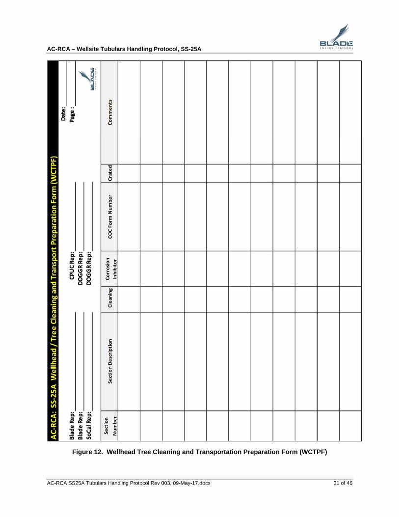
8. The cleaning and crating process will be documented using the Wellhead/Tree Cleaning and Transport Preparation Form (WCTP) as shown in Figure 12.
9. The Blade representative will complete the Chain of Custody (COC) forms as described in Appendix 5.3. The COC procedures will document the possession and the transfer/movement history of all sections.

AC-RCA – Wellsite Tubulars Handling Protocol, SS-25A
AC-RCA SS25A Tubulars Handling Protocol Rev 003, 09-May-17.docx 8 of 46
4 Tubing Handling Procedures
All work in this protocol is being directed by Blade.
All well and wellbore equipment, including tubing, shall be considered potential evidence. Therefore, every effort shall be taken to improve the chance for recovery of tubing and downhole equipment and to avoid inadvertent damage to equipment and/or evidence. During extraction of the tubing the threads may be damaged or galled. Every attempt will be made to mitigate any potential thread damage as a result of tubing extraction. Mitigation against this potential damage includes careful attention to tool selection, operational procedures and process. This implies careful service equipment selection and adhering to procedures that emphasize care over speed when removing the tubing.
Care should be exercised when running tools through the casing. It is important to recognize that the collection of logging data may mildly alter the condition of the casing. For example, the multi-finger caliper and the wellbore casing scraper tool and wire scratcher / brushes tool make contact with the ID of the casing. There may be tool marks on the casing as a result of the contact. The operations sequence and pictures of each tool before and after each run can be used to distinguish tool marks from the pre-existing marks.
The following procedures will be followed while extracting the tubing from SS-25A, and preparing the joints for transportation and storage. The tubing string and associated completion equipment is expected to be pulled from 8,215 ft and will consist of the following:
3-1/2" 9.3 ppf N80 with API EUE connections - 343 ft or 11 joints.
5-1/2" 20.0 ppf N80 with API LTC connections - 7,794 ft or 202 joints
2-7/8" 6.4 ppf N80 with API 8RD connection - 31 ft or 1 joint
Details about the completion equipment are provided in Appendix 5.4.
The recommended make-up torque range for these connections per API RP5C1 is as follows:
Table 1. Tubing Make-up Torques
OD Wt Conn Conn OD Minimum Optimum Maximum
3‐1/2" 9.3 EUE 4.500" 2400 ft‐lbs 3200 ft‐lbs 4000 ft‐lbs
5‐1/2" 20.0 LTC 6.505" 4350 ft‐lbs 5800 ft‐lbs 7250 ft‐lbs
2‐7/8" 6.4 EUE 3.668" 1730 ft‐lbs 2300 ft‐lbs 2880 ft‐lbs
Special Requirements:
Thread protectors, pin and box, closed end. Low-marking tong dies (with conventional dies as a backup) Bolsters Casing crew and torque-turn equipment Cleaning and Corrosion inhibitor application

AC-RCA – Wellsite Tubulars Handling Protocol, SS-25A
AC-RCA SS25A Tubulars Handling Protocol Rev 003, 09-May-17.docx 9 of 46
Rig Floor Procedures
A Blade representative will document the extraction of each joint and individual completion component using the Rig Floor Tubulars Extraction Form (RFTEF) as shown in Figure 8.
Note: individual completion components include – crossovers, gas lift mandrel, sliding sleeve, wireline nipples, packers, etc.
2. Draw vertical Orientation Line on the box.
3. Write the Joint Sequence Number on the pipe body just below the connection using a paint stick.
The Joint Sequence Numbering format should be T001, T002, etc., for full joints and individual completion components.
Enter the Joint Sequence Number on the RFTEF.
4. Visually examine the connection to determine if there is any observable damage, and then photograph the connection ensuring that the Joint Sequence Number is also visible in the connection photograph.
5. Break out the connection using tubing tongs and a torque-turn monitoring system.
Record the breakout torque on the RFTEF.
Record the breakout torque vs. turns electronically using the torque-turn monitoring system.
6. Install a thread protector on the pin.
Do not apply any thread compound to the connection
7. Lay down the joint onto the pipe rack using a pipe wrangler or crane taking care to prevent impact loads.
8. Latch the elevators onto the next joint, and POOH with the joint.
a. Record the string weight (hookload) on the RFTEF.
b. Record the drag on the RFTEF.
c. Pick up smoothly and slowly. Monitor the weight indicator closely.
d. Any anomalies observed while pulling the joint will be recorded on the RFTEF.
Avoid any sudden shock loads coming off of or setting the slips.
9. Set the slips when the next connection clears the rotary table.
Write the Joint Sequence Number again on the pipe body near the pin end just above the box of the next joint. The Joint Sequence Number should therefore be written twice on each joint as shown in Figure 2.
10. Check for the presence of H2S and CO2 using Draeger tubes at least every 5 joints pulled. Take the measurements at the rotary table level in a consistent manner. Record all readings on the RFPTF. Check for H2S more frequently if non-zero readings are noted.
11. Continue pulling the subsequent tubing joints in this manner.
12. Once all the tubing has been pulled, a report showing the torque vs. turns chart for each connection backed out will be generated from the torque-turn monitoring system.

AC-RCA – Wellsite Tubulars Handling Protocol, SS-25A
AC-RCA SS25A Tubulars Handling Protocol Rev 003, 09-May-17.docx 10 of 46
Pipe Rack Procedures
A Blade representative will conduct and document the visual inspection of each joint using the Pipe Rack Inspection Form (PRIF) as shown in Figure 9.
1. As a joint is placed onto the pipe rack, record the Joint Sequence Number on the PRIF.
2. Measure the pH of the fluid on the joint surface at a minimum of one and preferably three locations along the length of the joint using pH paper. If the pH cannot be measured, the reason should also be documented on the PRIF.
3. For each joint, measure the Tally Length (TL) from the coupling face to the pin face (excluding the pin threads) as shown in Figure 2, and record the length on the PRIF.
4. Visually inspect the OD of the pipe and coupling. The visual inspection will be followed with photographic documentation of the pipe body. Every observable flaw will be documented photographically. Absence of flaws will be noted, and one to two representative locations on the joint will be documented using photographs. The details on conducting the visual inspection are provided in Appendix 5.1. The focus of the visual inspection is primarily the OD of the tubing. ID examination requires other NDE techniques.
5. Samples of any scale or corrosion product, or other solid material present on the pipe surface will be collected.
6. Any flaw that is located will be cleaned and protectively wrapped, if appropriate and necessary, as described in Section 5.1. There may be certain scenarios where there is a flaw surface that should not be cleaned in to order preserve the surface or the scale and/or corrosion product. These decisions will be made by Blade on a case-by-case basis after an onsite assessment of the flaw.
7. Enter the classification disposition (Flawed or No Flaws) of the joint, and any other relevant comments about the condition of the joint onto the PRIF.
8. Permanently mark the Joint Sequence Number at both ends of the joint and on either end of individual completion components.
9. An Evidence Data Sheet will then be completed for each joint per Appendix 5.3.
10. Continue inspecting each subsequent joint as they are laid down in this manner.
Figure 2. Tubing Joint Measurement and Numbering Locations
T042 T042
Coupling PinJoint sequence numbers
Tally Length (TL)

AC-RCA – Wellsite Tubulars Handling Protocol, SS-25A
AC-RCA SS25A Tubulars Handling Protocol Rev 003, 09-May-17.docx 11 of 46
11. Joints that have large flaws will require special care. Additional onsite inspection of the flaw surface will be conducted, and additional steps taken to preserve the flaw.
Detailed examination of the flaw will be taken immediately after the joint is on the rig floor before it is laid down on the pipe rack. It may be necessary to clean, visually inspect and document the flaw inspection before the joint is laid down depending on the nature, condition and extent of the flaw.
Sectioning of the joint on the pipe rack to remove the flaw section so that it can be adequately preserved and protected may be required. Sectioning will be done outside the damaged location on the joint.
Pipe Cleaning and Preservation for Transport and Storage:
After visual inspection, every joint will require further treatment for transportation and storage. It is anticipated the tubulars will be required to be stored for an extended period. The cleaning and preservation procedures are intended to mitigate changes during storage. A Blade representative will witness and document the cleaning of each joint using the Pipe Cleaning and Transport Preparation Form (PCTPF) as shown in Figure 10.
Every joint will go through the following process in preparation for transportation and storage.
1. As described in Section 5.2, the entire joint will require cleaning using a brush and low pressure water spray and/or a cleaner.
2. Following cleaning, a visual inspection will be conducted and the flaws will be documented per Appendix 5.1.
3. Then the joint will be treated with a corrosion inhibitor fluid that will protect the carbon steel and mitigate corrosion due to moisture and oxygen exposure over an extended storage period.
4. After the corrosion inhibitor has cured, Volatile Corrosion Inhibitor (VCI) (reference Appendix 5.9) will be inserted into the ID of each joint of tubing, and then the pin and box protectors will be installed.
5. The cleaning process for joints that have large flaws will be finalized after initial observation and will be commensurate with the type and nature of the flaw. In general, the process will include:
The flaw surface will be cleaned, if appropriate. There may be certain types of flaws that need to be preserved in the condition retrieved; the process of cleaning may damage the corrosion or scale product or the flaw fracture surface; in these cases the flaws may not be cleaned.
A corrosion inhibitor, if appropriate, will then be applied to protect the flaw surface.
The region around the flaw will be protected. Any general cleaning in the region will be carefully completed without impacting the flaw surface.
Transport Preparation Procedures
AC-RCA – Wellsite Tubulars Handling Protocol, SS-25A
AC-RCA SS25A Tubulars Handling Protocol Rev 003, 09-May-17.docx 12 of 46
A Blade representative will witness and document the loading of the joints onto the trucks for transport to the storage facility.
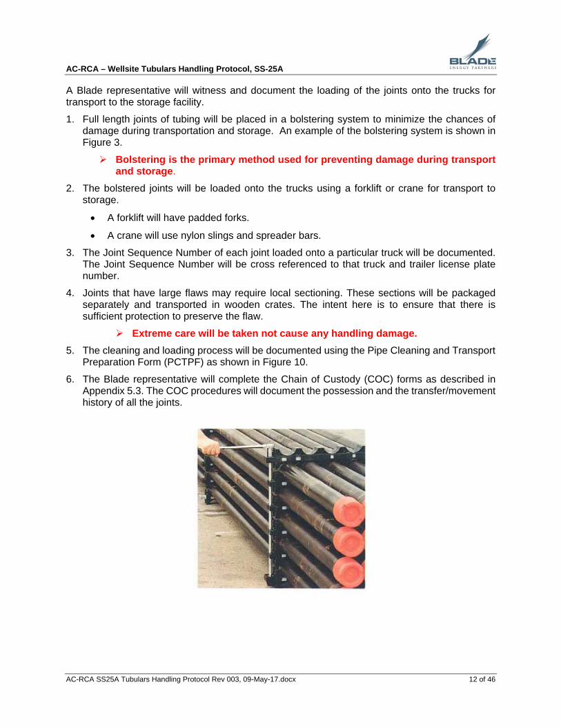
1. Full length joints of tubing will be placed in a bolstering system to minimize the chances of damage during transportation and storage. An example of the bolstering system is shown in Figure 3.
Bolstering is the primary method used for preventing damage during transport and storage.
2. The bolstered joints will be loaded onto the trucks using a forklift or crane for transport to storage.
A forklift will have padded forks.
A crane will use nylon slings and spreader bars.
3. The Joint Sequence Number of each joint loaded onto a particular truck will be documented. The Joint Sequence Number will be cross referenced to that truck and trailer license plate number.
4. Joints that have large flaws may require local sectioning. These sections will be packaged separately and transported in wooden crates. The intent here is to ensure that there is sufficient protection to preserve the flaw.
Extreme care will be taken not cause any handling damage.
5. The cleaning and loading process will be documented using the Pipe Cleaning and Transport Preparation Form (PCTPF) as shown in Figure 10.
6. The Blade representative will complete the Chain of Custody (COC) forms as described in Appendix 5.3. The COC procedures will document the possession and the transfer/movement history of all the joints.

AC-RCA – Wellsite Tubulars Handling Protocol, SS-25A
AC-RCA SS25A Tubulars Handling Protocol Rev 003, 09-May-17.docx 13 of 46
Figure 3. Bolstering System Example

AC-RCA – Wellsite Tubulars Handling Protocol, SS-25A
AC-RCA SS25A Tubulars Handling Protocol Rev 003, 09-May-17.docx 14 of 46
5 Appendix
The following supplemental information is provided in this section.
Section 5.1: Visual Inspection Procedures
Section 5.2: Joint Cleaning and Corrosion Protection Procedures
Section 5.3: Evidence Data Sheet & Chain of Custody Forms
Section 5.4: Tubulars Performance Data
Section 5.5: Extraction Documentation Forms
Section 5.7: Tectyl 506 Product Information
Section 5.6: Sentinel 747 Cleaning Product Information
Section 5.8: Tectyl 846 Class 1 Corrosion Inhibitor Product Information
Section 5.9: Volatile Corrosion Inhibitor (VCI) Product Information

AC-RCA – Wellsite Tubulars Handling Protocol, SS-25A
AC-RCA SS25A Tubulars Handling Protocol Rev 003, 09-May-17.docx 15 of 46
5.1 Visual Inspection Procedures
The focus of the visual inspection is primarily the OD of the tubing. ID examination requires other NDE techniques. The intent of the visual inspection is to document the as-recovered downhole condition of the tubulars (flawed or not) extracted from the well. The objective is to:
Identify any metal loss damage (e.g. pits, wall thickness loss or other corrosion that may undermine load and pressure containment) on the tubing, and/or connections.
Identify any indications of ductile overload; plasticity and/or deformation.
Identify any large cracks in the body of the joints and/or connection.
Identify any scars, slip marks, tong marks, and any associated handling damage on the tubing, and/or connections.
Identify presence and/or absence of deformations on the pipe joints, and/or connections.
Identify presence or absence of corrosion products.
Identify whether there was any over torqueing, and/or other signs of damage.
Note that while the procedures described below focus on the tubing, the same philosophy will be applied to the inspection of the wellhead sections.
The inspection will be conducted as follows:
1. Ensure that the Joint Sequence Numbers and Orientation mark are clearly legible.
2. Examine the full length of the joint from the coupling/upper end to the pin/lower end.
3. If a flaw is observed, write the number “1” next to the flaw using a paint marker or paint stick. If another flaw is observed, write the number “2” next to it and so on for each flaw identified.
4. Rotate and examine the joint marking the location of any flaws.
5. Continue this process until the full circumference of the joint has been examined.
6. Photographically document the inspection as follows:
a. Begin by taking a picture of the coupling end of the joint with the Joint Sequence Number visible in the picture.
b. Photograph all of the flaws that were observed.
flaws will be photographed with an index card placed next to the flaw. The Joint Sequence Number will be written on the index card. The flaw number should be visible in the picture.
flaws will also be photographed with a scale placed alongside to indicate size.
the distance from the flaw to the coupling or pin end will be measured and recorded.
if no flaws are observed, take several pictures that represent the overall condition of the joint.
c. End by taking a picture of the Joint Sequence Number at the pin end of the joint.
d. All photographs will be backed up to a hard drive at the end of each day.

AC-RCA – Wellsite Tubulars Handling Protocol, SS-25A
AC-RCA SS25A Tubulars Handling Protocol Rev 003, 09-May-17.docx 16 of 46
7. Scale and/or corrosion product or other solids on the pipe surface will be collected after photographing.
A soft metal (e.g. brass) or plastic scraper/spatula will be used to collect the samples.
Scale/corrosion and solid samples will be collected in a sample container. Collect as much as reasonably possible. Target to collect at least 2 to 5 grams.
If there is extensive scale/corrosion on a joint, then one sample each should be taken from 3 to 5 different locations.
Clean the scraper/spatula with acetone and then rinse with distilled water before each use.
8. Document the results in the PRIF and the Evidence Data Sheet.
9. At night, the inspection area should be illuminated using portable equipment providing a light level of at least 50 ft-candles (500 lux) as per API 5A5 (Field Inspection of Casing, Tubing and Plain-End Drill Pipe).
The preservation and protection of flaws will be done as follows:
The nature, condition and extent of the flaw will dictate the measures that need to be taken to preserve and protect the flaw for transport. The base case preservation plan is to clean and protect each flaw. Protection for most flaws is provided by the bolstering system, which prevents metal to metal contact and handling damage. Preservation is addressed through the application of the corrosion inhibitor. The exact measures that need to be taken will be determined by Blade at the time. The general process is as follows:
1. As a general guideline, the flaw location will first be cleaned, unless determined that it is better preserved without any further cleaning. There may be a case, for example, where the flaw is a tight crack that is better left as-is rather than cleaning and introducing a fluid into the crack that might damage the surface. Such a determination will be made onsite by Blade on a case-by-case basis.
If the flaw is small, then acetone will applied using a soft paint brush to clean the flaw surface and surrounding area. Any general cleaning in the region will be carefully completed without impacting the flaw surface.
After the area has been allowed to air dry, Tectyl 506 corrosion inhibitor (reference Appendix 5.6) will be applied on the flaw surface and the surrounding area, as per ASM (American Society of Metals) handbook Volume 12, page 73.
If the flaw is large, then low pressure water spray will be used to clean the flaw surface and surrounding area. After the area has been allowed to air dry, Tectyl 506 corrosion inhibitor will be applied using a soft paint brush for protection of the flaw surface and surrounding area.
2. Flaws requiring additional protection.
Wrap the flaw area to preserve the area in its current condition, and prevent further damage. VCI impregnated packaging material (reference Appendix 5.9) will be utilized to supplement the Tectyl 506 coating by providing an additional corrosion inhibiting barrier. Preservation materials include VCI stretch film, VCI foam packaging, or other protective covers.

AC-RCA – Wellsite Tubulars Handling Protocol, SS-25A
AC-RCA SS25A Tubulars Handling Protocol Rev 003, 09-May-17.docx 17 of 46
If it is determined that the flaw cannot be adequately be preserved and/or protected in its as-is condition on the joint, the flaw area will be sectioned and removed from the joint to be handled separately. Sectioning will be done outside the damaged location on the joint. Prior to sectioning ultrasonic or other inspection methods will be utilized to ensure that there are no ID flaws in the area where the cut is to be made.
3. Other considerations:
Do not mechanically clean, sandblast, wire-brush, or acid clean any flaws.
When handling sections containing the flaw area, care must be taken to preserve specimens in the as-recovered condition.
If a joint is fractured into two or more separate pieces, do not fit the fracture surfaces back together.

AC-RCA – Wellsite Tubulars Handling Protocol, SS-25A
AC-RCA SS25A Tubulars Handling Protocol Rev 003, 09-May-17.docx 18 of 46
5.2 Cleaning and Corrosion Protection Procedures
After visual inspection, each joint will be cleaned, re-inspected, and a corrosion inhibitor will be applied as described below. It is envisioned that this will involve moving the joint from the pipe rack to a separate cleaning station.
Note that while the procedures described above focus on the tubing, the same philosophy will be applied to the cleaning and the application of corrosion inhibitor to the internal wellhead sections.
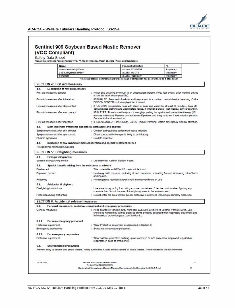
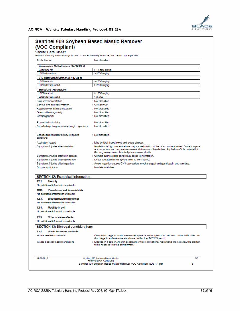
1. The outer circumference of the joint will be cleaned with a brush and low pressure water spray and/or Sentinel 909 cleaner (or equivalent, reference Appendix 5.7) depending on the condition of the surface.
The water used for cleaning will be the municipal water available at Aliso Canyon.
Brushes will have stiff plastic bristles.
2. The internal area of the joint will then be cleaned with a brush and low pressure water spray and/or Sentinel 909 cleaner using a lance to direct the spray inside the joint. Spraying will be done from both ends of the joint.
3. The joint will be allowed to air dry or compressed air will be used to remove moisture.
4. Re-apply the Joint Sequence number on both ends of the joint.
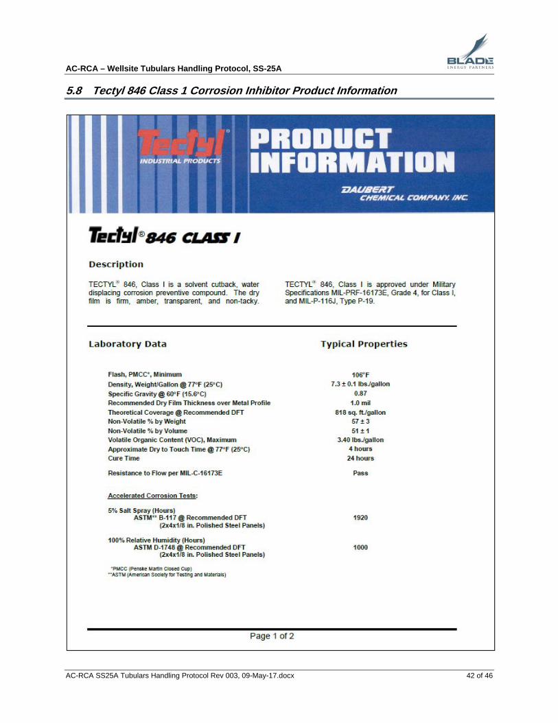
5. Tectyl 846 Class 1 corrosion inhibitor (reference Appendix 5.8) will be applied to the OD. Tectyl 846 (or equivalent) or a VCI product will be applied to the ID.
Tectyl 846 is the base case product for ID corrosion protection. However, a different VCI product may be used to replace the Tectyl 846 for ID protection, in which case the subsequent steps will be adjusted.
6. The Tectyl 846 should be dry to touch after 4 hours at 77°F. After 4 hours, evaluate the corrosion inhibitor condition to allow bolstering.
7. Volatile Corrosion Inhibitors (VCI) will be used to augment the protection provided by Tectyl 846 by providing supplemental ID protection for the tubing.
Therefore prior to bolstering:
VCI will be inserted into the ID of each joint of tubing, and the pin and box thread protectors will be installed.

AC-RCA – Wellsite Tubulars Handling Protocol, SS-25A
AC-RCA SS25A Tubulars Handling Protocol Rev 003, 09-May-17.docx 19 of 46
5.3 Evidence Data Sheet & Chain of Custody
An Evidence Data Sheet will be generated for every tubing joint extracted from the wellbore as well as for each section removed from the wellhead/tree. The Evidence Data Sheet will contain all the relevant data for each individual joint or wellhead section including quantitative measurements such as pH, dimensional measurements, visual observations and so on.
The Evidence Data Sheet for tubing will use the Joint Sequence Number as a unique traceability identifier. The Evidence Data Sheet for Wellhead/Tree will use the Section Number as a unique traceability identifier.
Corrosion/scale samples that are collected will be considered “samples" of the parent joint. Each sample will be identified by a unique Sample Number that will tie the sample back to the parent joint. The Sample Number will be generated by adding S1, S2, S3, and so on to the Joint Sequence Number.
Example: if a scale sample is taken from joint number T001, the scale Sample Number will be “T001S1”. A label with the sample number will be affixed to the bag containing the sample.
If a portion of a tubing joint is cut and removed, the cut section will be considered as a "section" of the parent joint. Each section will be identified by a unique Section Number that will tie the section back to the parent joint. The Section Number will be generated by adding 'A', 'B', 'C' and so on to the Joint Sequence Number. This Section Number will be stenciled on the OD of the cut section.
Example: If a section is cut/removed from joint number T001, the Section Number for the different sections will be identified as “T001A", "T001B" and so on.
Likewise, if a wellhead section is disassembled a unique letter will be assigned to each of the sub-sections. For example, if section W001 is disassembled the different sub-sections will be "W001A", "W001B" and so on.
A separate Evidence Data Sheet will be generated for each sample or section described above.
A separate COC form will be generated for each sample or section. The Evidence Data Sheet will also have a link to the COC Form Number.
This process for identifying samples/sections will be followed regardless of whether, for example, a joint is sectioned locally or at different location.
Once completed, Blade will retain the original form and a scanned copy of the Evidence Data Sheet will be made. As such, there will be a unique identifier for everything that is extracted from SS-25A. Examples of Evidence Data Sheet forms are shown in Figure 4 and Figure 5.

AC-RCA – Wellsite Tubulars Handling Protocol, SS-25A
AC-RCA SS25A Tubulars Handling Protocol Rev 003, 09-May-17.docx 20 of 46
Chain of Custody Process
The Chain of Custody (COC) form documents the possession and transfer/movement history of the tubing, sections and samples that are extracted or removed. Each COC form will have a COC Form Number that will be linked to individual Evidence Data Sheets through the Joint Sequence Number or Section Number.
Wellhead/Tree COC Each wellhead section will have its own individual COC form. The Section Number will be entered on the COC form, and the COC Form Number will be entered on the Evidence Data Sheet.
The wellhead COC Form Numbers will be as follows:
Wellhead sections: AC-RCA-25A-W001, AC-RCA-25A-W002, AC-RCA-25A-W003….
Tubing COC Every tubing joint will have its own COC form.
The Joint Sequence Number for each joint covered under a particular COC form will be entered on the COC form, and the COC Form Number will also be entered on the Evidence Data Sheet for each joint covered under the COC form.
The tubing COC Form numbers will be as follows:
Tubing joints: AC-RCA-25A-T001, AC-RCA-25A-T002, AC-RCA-25A-T003…
Once completed, a scanned copy of the COC form will be made. The original tubing COC forms will travel with the bolsters and/or crated sections. Original wellhead COC forms will travel with the crate for that section. The COC forms will therefore travel with the joint/section as it is moved from one location to another. The receiver will be instructed to complete the COC form upon receipt of the evidence and a copy will be sent to the Blade RCA team. The movement history will be recorded in the Blade COC log.
As such, the movement history of every tubing joint and wellhead section that is extracted from the wellbore will be identified and tracked. Examples of Chain of Custody forms are shown in Figure 6 and Figure 7.

AC-RCA – Wellsite Tubulars Handling Protocol, SS-25A
AC-RCA SS25A Tubulars Handling Protocol Rev 003, 09-May-17.docx 21 of 46
Figure 4. Wellhead/Tree Evidence Data Sheet

AC-RCA – Wellsite Tubulars Handling Protocol, SS-25A
AC-RCA SS25A Tubulars Handling Protocol Rev 003, 09-May-17.docx 22 of 46
Figure 5. Tubing Evidence Data Sheet

AC-RCA – Wellsite Tubulars Handling Protocol, SS-25A
AC-RCA SS25A Tubulars Handling Protocol Rev 003, 09-May-17.docx 23 of 46
Figure 6. Tubing COC Forms

AC-RCA – Wellsite Tubulars Handling Protocol, SS-25A
AC-RCA SS25A Tubulars Handling Protocol Rev 003, 09-May-17.docx 24 of 46
Figure 7. Wellhead/Tree COC Form

AC-RCA – Wellsite Tubulars Handling Protocol, SS-25A
AC-RCA SS25A Tubulars Handling Protocol Rev 003, 09-May-17.docx 25 of 46
5.4 Tubular Performance Data
For reference, dimensional and performance data for the tubulars that were run in the SS-25A well is provided below.
Table 2. Casing and Tubing Data
Tubulars Data
OD Weight Nom Wall Nom ID Drift ID Length Air Wt
(in) (ppf) (in) (in) (in) Hanger Base ft lbs
Conductor ? ? ? ? ? ? ? ? ? ? ‐‐‐
Surface 13‐3/8" 48.0 H40 0.330 12.715 12.559 0 806 806 STC 38,688
36.0 K55 0.400 7.825 7.700 0 2,970 2,970 BTC 106,920
Homco Casing Patch ‐‐‐ 7.525 7.400 2,970 3,010 40 ‐‐‐ ‐‐‐
36.0 K55 0.400 7.825 7.700 3,010 5,422 2,412 BTC 86,832
36.0 N80 0.400 7.825 7.700 5,422 8,112 2,690 BTC 96,840
6‐5/8"L 27.65 K55 0.417 5.791 5.666 7,926 8,908 982 Vetco FJ 27,152
3‐1/2" 9.3 N80 0.254 2.992 2.867 0 50 50 EUE 465
5‐1/2" 20.0 N80 0.361 4.778 4.653 50 7,854 7,804 LTC 156,080
3‐1/2" 9.3 N80 0.254 2.992 2.867 7,854 8,184 330 EUE 3,069
2‐7/8" 6.4 N80 0.217 2.441 2.347 8,184 8,215 31 EUE 198
Tubing
Production
ConnSetting Depths (MD)
8‐5/8"
String Grade
Tubulars Nominal Performance
OD Weight Pipe Data Connection Data
(in) (ppf) Nom Wall Burst Collapse Tension OD ID Burst Tension
Conductor 20" ? ? ? ? ? ? ? ? ? ? ?
Surface 13‐3/8" 48.0 H40 STC 0 1,730 740 541,000 14.375 12.715 1,730 322,000
36.0 K55 BTC 0.400 4,460 3,450 568,000 9.625 7.825 4,460 780,000
36.0 N80 BTC 0.400 6,490 4,100 827,000 9.625 7.825 6,490 895,000
6‐5/8"L 27.65 K55 Vetco FJ 0.417 6,060 6,170 447,000 ? ? ? ?
3‐1/2" 9.3 N80 EUE 0.254 10,160 10,540 207,200 4.500 2.992 10,160 207,200
5‐1/2" 20.0 N80 LTC 0.361 9,190 8,830 466,000 6.050 4.778 9,190 428,000
3‐1/2" 9.3 N80 EUE 0.254 10,160 10,540 207,200 4.500 2.992 10,160 207,200
2‐7/8" 6.4 N80 EUE 0.217 10,570 11,170 145,000 3.668 2.441 10,570 145,000
Tubing
String Grade
Production8‐5/8"
Conn

AC-RCA – Wellsite Tubulars Handling Protocol, SS-25A
AC-RCA SS25A Tubulars Handling Protocol Rev 003, 09-May-17.docx 26 of 46
Table 3. Tubing String Details
Description OD (in) ID (in)Length
(ft)
Top of
Tool (ft)
Bottom
of Tool
(ft)
DFE 15.00
Tubing Hanger 7.825 2.992 0.46 15.00 15.46
Pup Joint 3‐1/2" 9.3ppf EUE N‐80 Tubing (0.007985bpf) 3.500 2.992 1.58 15.46 17.04
1 Joint 3‐1/2" 9.3ppf EUE N‐80 Tubing 3.500 2.992 31.10 17.04 48.14
Crossover 3‐1/2" x 5‐1/2" 5.500 2.992 1.58 48.14 49.72
202 joints 5‐1/2" 20ppf N‐80 LTC (0.02103bpf) 5.500 4.778 7,794.30 49.72 7,844.02
Crossover 5‐1/2" x 3‐1/2" 5.500 2.992 1.26 7,844.02 7,845.28
1 Joint 3‐1/2" 9.3ppf EUE N‐80 Tubing 3.500 2.992 31.18 7,845.28 7,876.46
Pup Joint 3‐1/2" 9.3ppf EUE N‐80 Tubing 3.500 2.992 3.70 7,876.46 7,880.16
Gas Lift Mandrel 3.500 2.992 6.12 7,880.16 7,886.28
Pup Joint 3‐1/2" 9.3ppf EUE N‐80 Tubing 3.500 2.992 4.20 7,886.28 7,890.48
7 Joints 3‐1/2" 9.3ppf EUE N‐80 Tubing 3.500 2.992 218.21 7,890.48 8,108.69
Sliding Sleeve 3.500 2.813 4.25 8,108.69 8,112.94
1 Joint 3‐1/2" 9.3ppf EUE N‐80 Tubing 3.500 2.992 31.18 8,112.94 8,144.12
XN Nipple 3.500 2.635 1.40 8,144.12 8,145.52
1 Joint 3‐1/2" 9.3ppf EUE N‐80 Tubing 3.500 2.992 31.22 8,145.52 8,176.74
Crossover 3‐1/2" x 2‐7/8" 3.500 2.441 1.10 8,176.74 8,177.84
COE 3.500 2.365 2.65 8,177.84 8,180.49
HES G77 Packer 5.515 2.365 3.39 8,180.49 8,183.88
Ball catcher 2.875 2.441 0.38 8,183.88 8,184.26
1 Joint 2‐7/8" 6.4ppf 8rd N‐80 Tubing 2.875 2.441 30.69 8,184.26 8,214.95
Casing patch 2,970 ‐ 3,010'
Otis Permatrive Packer at 8,200'
HES G77 Packer at 8,180'
Tubing Up Wt 158k. Tubing Down Wt 134k.
Landed with 12,000 lb on Packer

AC-RCA – Wellsite Tubulars Handling Protocol, SS-25A
AC-RCA SS25A Tubulars Handling Protocol Rev 003, 09-May-17.docx 27 of 46
5.5 Extraction Documentation Forms
Figure 8. Rig Floor Tubulars Extraction Form (RFTEF) Example

AC-RCA – Wellsite Tubulars Handling Protocol, SS-25A
AC-RCA SS25A Tubulars Handling Protocol Rev 003, 09-May-17.docx 28 of 46
Figure 9. Pipe Rack Inspection Form (PRIF) Example

AC-RCA – Wellsite Tubulars Handling Protocol, SS-25A
AC-RCA SS25A Tubulars Handling Protocol Rev 003, 09-May-17.docx 29 of 46
Figure 10. Pipe Cleaning and Transportation Preparation Form (PCTPF) Example

AC-RCA – Wellsite Tubulars Handling Protocol, SS-25A
AC-RCA SS25A Tubulars Handling Protocol Rev 003, 09-May-17.docx 30 of 46
Figure 11. Wellhead/Tree Inspection Form (WIP) Example
AC-RCA – Wellsite Tubulars Handling Protocol, SS-25A
AC-RCA SS25A Tubulars Handling Protocol Rev 003, 09-May-17.docx 31 of 46
Figure 12. Wellhead Tree Cleaning and Transportation Preparation Form (WCTPF)

AC-RCA – Wellsite Tubulars Handling Protocol, SS-25A
AC-RCA SS25A Tubulars Handling Protocol Rev 003, 09-May-17.docx 32 of 46
5.6 Tectyl 506 Corrosion Inhibitor Product Information

AC-RCA – Wellsite Tubulars Handling Protocol, SS-25A
AC-RCA SS25A Tubulars Handling Protocol Rev 003, 09-May-17.docx 33 of 46

AC-RCA – Wellsite Tubulars Handling Protocol, SS-25A
AC-RCA SS25A Tubulars Handling Protocol Rev 003, 09-May-17.docx 34 of 46
5.7 Sentinel 909 Cleaning Product Information

AC-RCA – Wellsite Tubulars Handling Protocol, SS-25A
AC-RCA SS25A Tubulars Handling Protocol Rev 003, 09-May-17.docx 35 of 46
AC-RCA – Wellsite Tubulars Handling Protocol, SS-25A
AC-RCA SS25A Tubulars Handling Protocol Rev 003, 09-May-17.docx 36 of 46

AC-RCA – Wellsite Tubulars Handling Protocol, SS-25A
AC-RCA SS25A Tubulars Handling Protocol Rev 003, 09-May-17.docx 37 of 46

AC-RCA – Wellsite Tubulars Handling Protocol, SS-25A
AC-RCA SS25A Tubulars Handling Protocol Rev 003, 09-May-17.docx 38 of 46
AC-RCA – Wellsite Tubulars Handling Protocol, SS-25A
AC-RCA SS25A Tubulars Handling Protocol Rev 003, 09-May-17.docx 39 of 46

AC-RCA – Wellsite Tubulars Handling Protocol, SS-25A
AC-RCA SS25A Tubulars Handling Protocol Rev 003, 09-May-17.docx 40 of 46

AC-RCA – Wellsite Tubulars Handling Protocol, SS-25A
AC-RCA SS25A Tubulars Handling Protocol Rev 003, 09-May-17.docx 41 of 46
AC-RCA – Wellsite Tubulars Handling Protocol, SS-25A
AC-RCA SS25A Tubulars Handling Protocol Rev 003, 09-May-17.docx 42 of 46
5.8 Tectyl 846 Class 1 Corrosion Inhibitor Product Information

AC-RCA – Wellsite Tubulars Handling Protocol, SS-25A
AC-RCA SS25A Tubulars Handling Protocol Rev 003, 09-May-17.docx 43 of 46

AC-RCA – Wellsite Tubulars Handling Protocol, SS-25A
AC-RCA SS25A Tubulars Handling Protocol Rev 003, 09-May-17.docx 44 of 46
5.9 Volatile Corrosion Inhibitor (VCI) Product Information
VCI are compounds that release molecules into the air which attach to metal surfaces forming a corrosion inhibiting layer a few molecules thick. An advantage of using VCI's is that the molecules will penetrate into inaccessible crevices and gaps thereby reaching complex surfaces that are difficult to coat with conventional products. VCI compounds can be added to various types of packaging and wrapping materials, and will therefore provide corrosion protection without having to be in direct contract with area being protected. VCI products that are compliant to US Military Performance or NACE specifications will be utilized.

AC-RCA – Wellsite Tubulars Handling Protocol, SS-25A
AC-RCA SS25A Tubulars Handling Protocol Rev 003, 09-May-17.docx 45 of 46

AC-RCA – Wellsite Tubulars Handling Protocol, SS-25A
AC-RCA SS25A Tubulars Handling Protocol Rev 003, 09-May-17.docx 46 of 46