Embed Size (px)
Citation preview

Community College of Allegheny County Unit 2 Page #1
Load Cells and the Arduino
Revised: Dan Wolf, 2/15/2018
Load Cells andLoad Cells and the Arduinothe Arduino
Community College of Allegheny County Unit 2 Page #2
OBJECTIVES: Measurement Concepts:
Strain Gauge / Load Cell / Wheatstone Amplifier Shield Based on AD8426 amplifier (RB-Onl-38 from Robotshop.com).
5Kg Micro Load cell using a wheatstone bridge sensor (RB-Phi-118 from Robotshop.com).
The Arduino microcontroller with a 10-bit A-D converter providing 4.88mV resolution.
DELIVERABLES THAT YOU MUST SUBMIT
1. Table #1, Graph#1, Graph#22. Practice Problems
On-Line Reading Material:Required:
1. http://www.sensorland.com/HowPage002.html
Optional:1. http://www.explainthatstuff.com/straingauge.html
Especially read the section titled “Electrical Resistance”.2. http://www.explainthatstuff.com/straingauge.html
INTRODUCTION:A strain gauge (or strain gage) is a device used to measure
strain on an object. It is a sensor whose resistance varies with applied force; It converts force, pressure, tension, weight, etc., into a change in electrical resistance which can then be measured. When external forces are applied to a stationary object, stress and strain are the result.
A load cell is a transducer that is used to create an electrical signal whose magnitude is directly proportional to the force being measured. The various types of load cells include hydraulic load cells, pneumatic load cells and strain gauge load cells.
In this unit, you will use a load cell which already has two strain gages attached. The load cell output voltage will be amplified and read by the Arduino microcontroller such that the load weight will be displayed on the computer screen.
Community College of Allegheny County Unit 2 Page #3
Figure 1 – Load Cell Setup
Known weight inducing stress not to exceed 5Kg.
Make sure the green arrow points down.
Make sure the C-clamp does not damage the white epoxy and is at the end of the load cell.
Arduino with RoboShop Load Cell amplifier mounted on top.

Community College of Allegheny County Unit 2 Page #4
EQUIPMENT REQUIRED:1. Strain Gauge / Load Cell / Wheatstone Amplifier Shield (2ch)
Product Code : RB-Onl-38 by RobotShop.2. 5 Kg Micro Load Cell, Product Code : RB-Phi-118 by Phidgets
(www.Robotshop.com).3. Arduino Uno, power supply, cable, and USB Hub.4. Two known weights, the largest must be less than 5Kg.5. “C” Clamp and string/twine
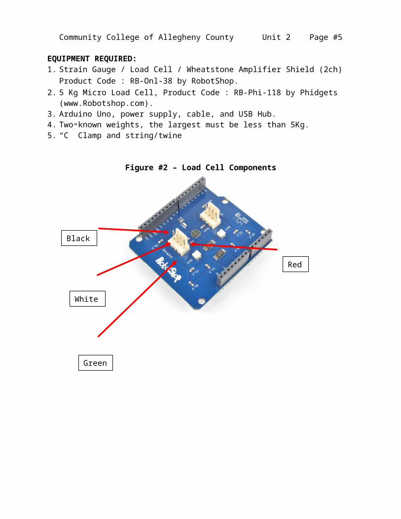
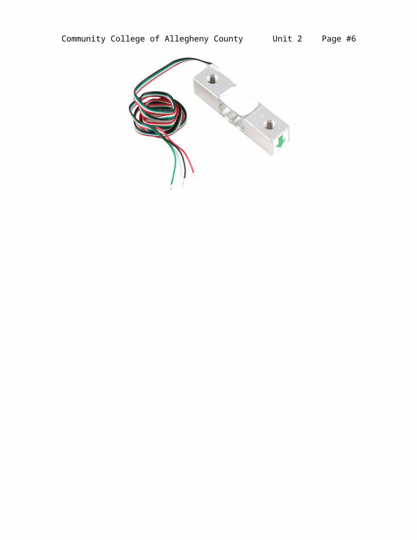
Figure #2 – Load Cell Components
Green
Red
Black
White
Community College of Allegheny County Unit 2 Page #5
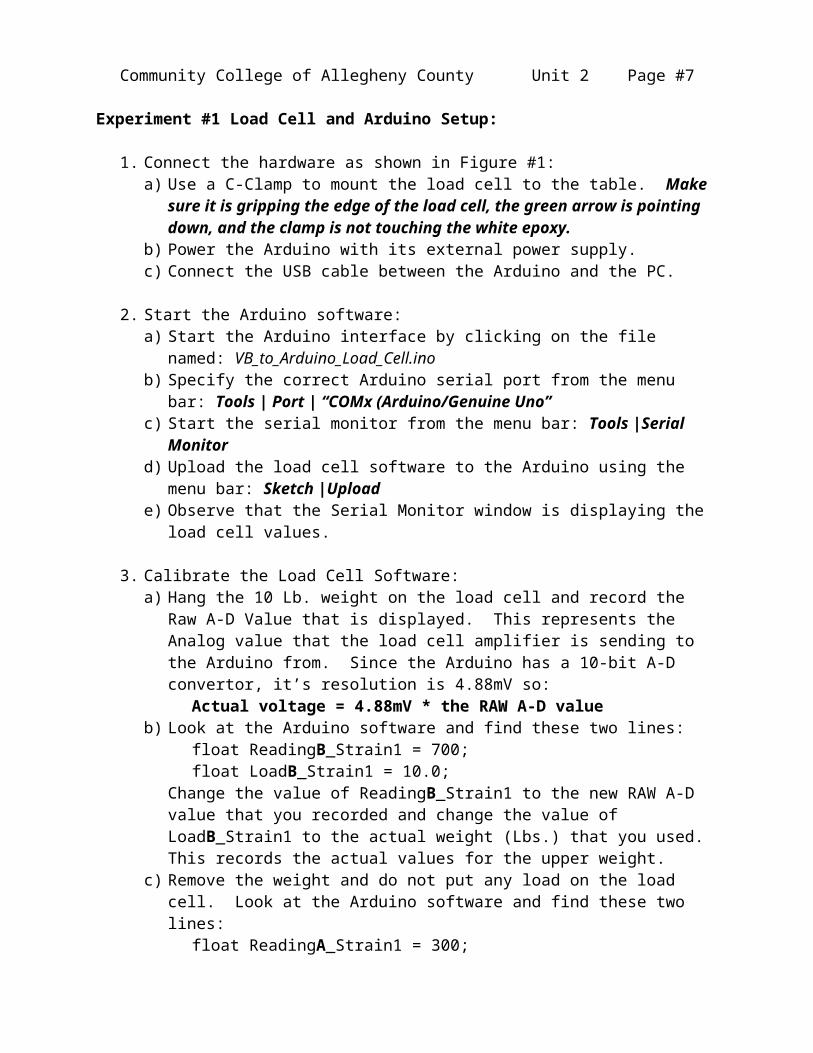
Experiment #1 Load Cell and Arduino Setup:
1. Connect the hardware as shown in Figure #1:a) Use a C-Clamp to mount the load cell to the table. Make
sure it is gripping the edge of the load cell, the green arrow is pointing down, and the clamp is not touching the white epoxy.
b) Power the Arduino with its external power supply.c) Connect the USB cable between the Arduino and the PC.
2. Start the Arduino software:a) Start the Arduino interface by clicking on the file
named: VB_to_Arduino_Load_Cell.inob) Specify the correct Arduino serial port from the menu
bar: Tools | Port | “COMx (Arduino/Genuine Uno”c) Start the serial monitor from the menu bar: Tools |Serial
Monitord) Upload the load cell software to the Arduino using the
menu bar: Sketch |Uploade) Observe that the Serial Monitor window is displaying the
load cell values.
3. Calibrate the Load Cell Software:a) Hang the 10 Lb. weight on the load cell and record the
Raw A-D Value that is displayed. This represents the Analog value that the load cell amplifier is sending to the Arduino from. Since the Arduino has a 10-bit A-D convertor, it’s resolution is 4.88mV so:
Actual voltage = 4.88mV * the RAW A-D valueb) Look at the Arduino software and find these two lines:
float ReadingB_Strain1 = 700; float LoadB_Strain1 = 10.0;
Change the value of ReadingB_Strain1 to the new RAW A-D value that you recorded and change the value of LoadB_Strain1 to the actual weight (Lbs.) that you used. This records the actual values for the upper weight.
c) Remove the weight and do not put any load on the load cell. Look at the Arduino software and find these two lines:
float ReadingA_Strain1 = 300; float LoadA_Strain1 = 0.0;
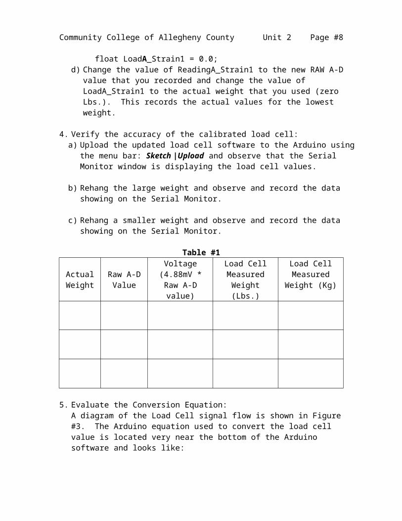
d) Change the value of ReadingA_Strain1 to the new RAW A-D value that you recorded and change the value of LoadA_Strain1 to the actual weight that you used (zero Lbs.). This records the actual values for the lowest weight.
Community College of Allegheny County Unit 2 Page #6
4. Verify the accuracy of the calibrated load cell:a) Upload the updated load cell software to the Arduino using
the menu bar: Sketch |Upload and observe that the Serial Monitor window is displaying the load cell values.
b) Rehang the large weight and observe and record the data showing on the Serial Monitor.
c) Rehang a smaller weight and observe and record the data showing on the Serial Monitor.
Table #1
Actual Weight
Raw A-D Value
Voltage (4.88mV * Raw A-D value)
Load Cell Measured Weight (Lbs.)
Load Cell Measured
Weight (Kg)
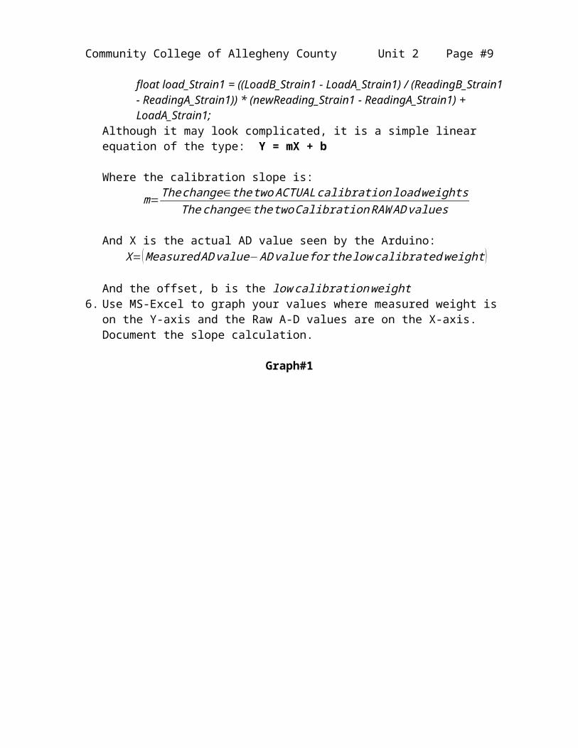
5. Evaluate the Conversion Equation:A diagram of the Load Cell signal flow is shown in Figure #3. The Arduino equation used to convert the load cell value is located very near the bottom of the Arduino software and looks like:
float load_Strain1 = ((LoadB_Strain1 - LoadA_Strain1) / (ReadingB_Strain1 - ReadingA_Strain1)) * (newReading_Strain1 - ReadingA_Strain1) + LoadA_Strain1;
Although it may look complicated, it is a simple linear equation of the type: Y = mX + b
Where the calibration slope is:
m=Thechange∈the two ACTUALcalibration loadweightsThechange∈thetwoCalibration RAW AD values
And X is the actual AD value seen by the Arduino:X=(Measured AD value−AD value for thelow calibratedweight )
And the offset, b is the low calibrationweight
Community College of Allegheny County Unit 2 Page #7
6. Use MS-Excel to graph your values where measured weight is on the Y-axis and the Raw A-D values are on the X-axis. Document the slope calculation.
Graph#1
Community College of Allegheny County Unit 2 Page #8
7. Create a second graph where A-D Voltage (4.88mV * Raw A-D value) is on the Y-axis and the Raw A-D values are on the X-axis.
Graph#2
Community College of Allegheny County Unit 2 Page #9
Figure #3 – Load Cell Signal Flow

Community College of Allegheny County Unit 2 Page #10
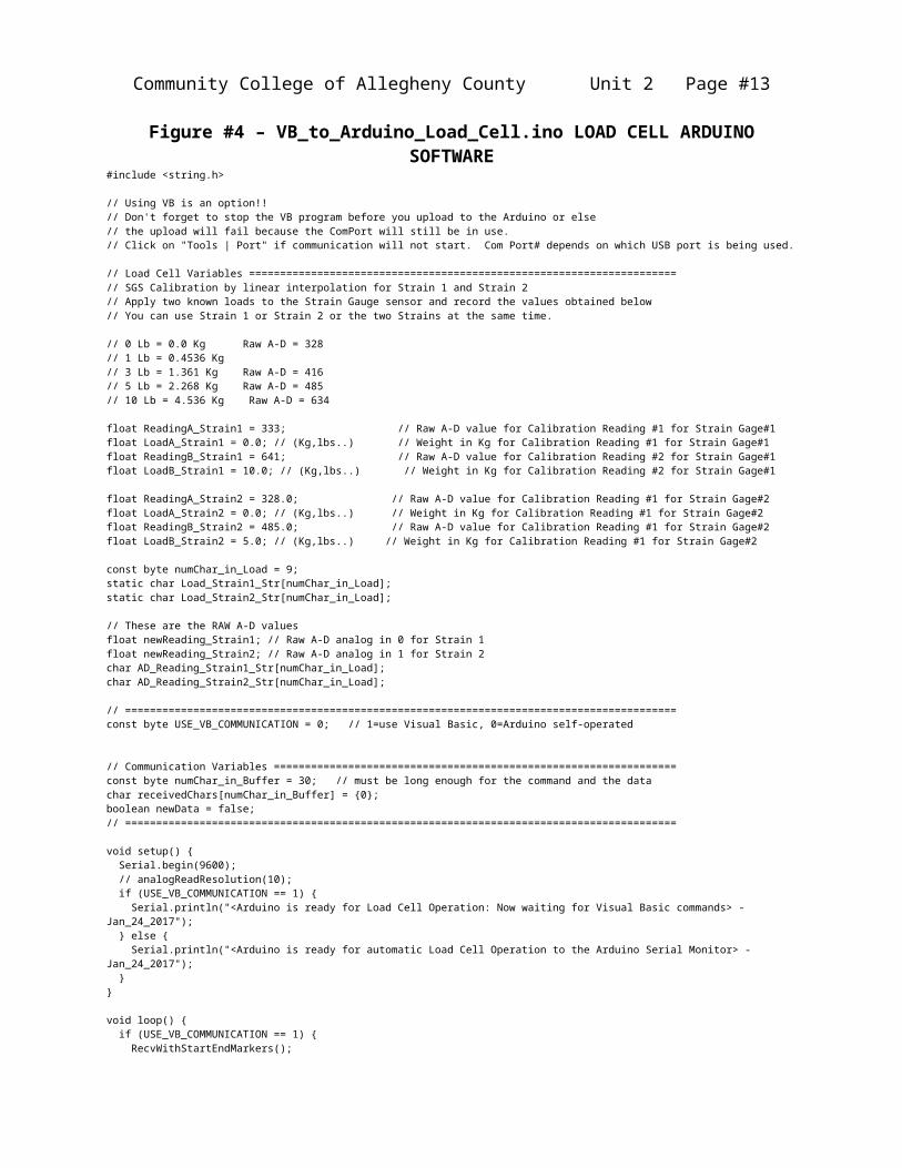
Figure #4 – VB_to_Arduino_Load_Cell.ino LOAD CELL ARDUINO SOFTWARE
#include <string.h>
// Using VB is an option!!// Don't forget to stop the VB program before you upload to the Arduino or else// the upload will fail because the ComPort will still be in use.// Click on "Tools | Port" if communication will not start. Com Port# depends on which USB port is being used.
// Load Cell Variables =====================================================================// SGS Calibration by linear interpolation for Strain 1 and Strain 2// Apply two known loads to the Strain Gauge sensor and record the values obtained below// You can use Strain 1 or Strain 2 or the two Strains at the same time.
// 0 Lb = 0.0 Kg Raw A-D = 328// 1 Lb = 0.4536 Kg// 3 Lb = 1.361 Kg Raw A-D = 416// 5 Lb = 2.268 Kg Raw A-D = 485// 10 Lb = 4.536 Kg Raw A-D = 634
float ReadingA_Strain1 = 333; // Raw A-D value for Calibration Reading #1 for Strain Gage#1float LoadA_Strain1 = 0.0; // (Kg,lbs..) // Weight in Kg for Calibration Reading #1 for Strain Gage#1float ReadingB_Strain1 = 641; // Raw A-D value for Calibration Reading #2 for Strain Gage#1float LoadB_Strain1 = 10.0; // (Kg,lbs..) // Weight in Kg for Calibration Reading #2 for Strain Gage#1
float ReadingA_Strain2 = 328.0; // Raw A-D value for Calibration Reading #1 for Strain Gage#2float LoadA_Strain2 = 0.0; // (Kg,lbs..) // Weight in Kg for Calibration Reading #1 for Strain Gage#2float ReadingB_Strain2 = 485.0; // Raw A-D value for Calibration Reading #1 for Strain Gage#2float LoadB_Strain2 = 5.0; // (Kg,lbs..) // Weight in Kg for Calibration Reading #1 for Strain Gage#2
const byte numChar_in_Load = 9;static char Load_Strain1_Str[numChar_in_Load];static char Load_Strain2_Str[numChar_in_Load];
// These are the RAW A-D valuesfloat newReading_Strain1; // Raw A-D analog in 0 for Strain 1float newReading_Strain2; // Raw A-D analog in 1 for Strain 2char AD_Reading_Strain1_Str[numChar_in_Load];char AD_Reading_Strain2_Str[numChar_in_Load];
// =========================================================================================const byte USE_VB_COMMUNICATION = 0; // 1=use Visual Basic, 0=Arduino self-operated
// Communication Variables =================================================================const byte numChar_in_Buffer = 30; // must be long enough for the command and the datachar receivedChars[numChar_in_Buffer] = 0;boolean newData = false;// =========================================================================================
void setup() Serial.begin(9600); // analogReadResolution(10); if (USE_VB_COMMUNICATION == 1) Serial.println("<Arduino is ready for Load Cell Operation: Now waiting for Visual Basic commands> - Jan_24_2017"); else Serial.println("<Arduino is ready for automatic Load Cell Operation to the Arduino Serial Monitor> - Jan_24_2017");
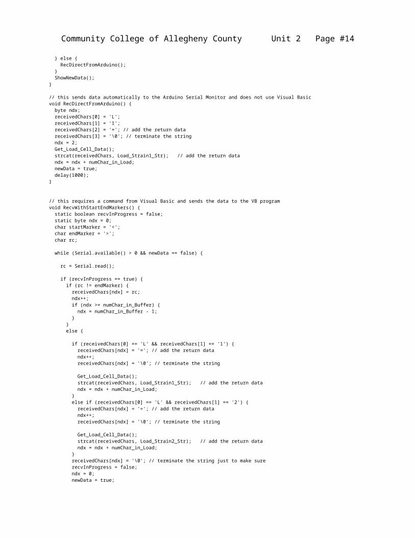
void loop() if (USE_VB_COMMUNICATION == 1) RecvWithStartEndMarkers(); else RecDirectFromArduino(); ShowNewData();
// this sends data automatically to the Arduino Serial Monitor and does not use Visual Basicvoid RecDirectFromArduino() byte ndx; receivedChars[0] = 'L'; receivedChars[1] = '1'; receivedChars[2] = '='; // add the return data receivedChars[3] = '\0'; // terminate the string ndx = 2; Get_Load_Cell_Data();

Community College of Allegheny County Unit 2 Page #11
strcat(receivedChars, Load_Strain1_Str); // add the return data ndx = ndx + numChar_in_Load; newData = true; delay(1000);
// this requires a command from Visual Basic and sends the data to the VB programvoid RecvWithStartEndMarkers() static boolean recvInProgress = false; static byte ndx = 0; char startMarker = '<'; char endMarker = '>'; char rc;
while (Serial.available() > 0 && newData == false)
rc = Serial.read();
if (recvInProgress == true) if (rc != endMarker) receivedChars[ndx] = rc; ndx++; if (ndx >= numChar_in_Buffer) ndx = numChar_in_Buffer - 1; else
if (receivedChars[0] == 'L' && receivedChars[1] == '1') receivedChars[ndx] = '='; // add the return data ndx++; receivedChars[ndx] = '\0'; // terminate the string
Get_Load_Cell_Data(); strcat(receivedChars, Load_Strain1_Str); // add the return data ndx = ndx + numChar_in_Load; else if (receivedChars[0] == 'L' && receivedChars[1] == '2') receivedChars[ndx] = '='; // add the return data ndx++; receivedChars[ndx] = '\0'; // terminate the string
Get_Load_Cell_Data(); strcat(receivedChars, Load_Strain2_Str); // add the return data ndx = ndx + numChar_in_Load; receivedChars[ndx] = '\0'; // terminate the string just to make sure recvInProgress = false; ndx = 0; newData = true; else if (rc == startMarker) recvInProgress = true;
void ShowNewData() // this echos/transmits the command back to the VB program
if (newData == true) Serial.print("Raw A-D Value: "); Serial.print(AD_Reading_Strain1_Str); // debug line shows data always Serial.print(" ");
Serial.print(receivedChars); // Serial.print(Load_Strain1_Str); // debug line shows data always Serial.println(" lbs>"); newData = false;
void Get_Load_Cell_Data() // this retreives the load cell data
newReading_Strain1 = analogRead(0); // analog in 0 for Strain 1 <=> 4.88mV * this value = Voltage from the load cell amplifier newReading_Strain2 = analogRead(1); // analog in 1 for Strain 2 <=> 4.88mV * this value = Voltage from the load cell amplifier

Community College of Allegheny County Unit 2 Page #12
dtostrf(newReading_Strain1, 8, 2, AD_Reading_Strain1_Str); // convert the float value to a string value dtostrf(newReading_Strain2, 8, 2, AD_Reading_Strain2_Str); // convert the float value to a string value
// Calculate the load by interpolation from the RAW A-D readings float load_Strain1 = ((LoadB_Strain1 - LoadA_Strain1) / (ReadingB_Strain1 - ReadingA_Strain1)) * (newReading_Strain1 - ReadingA_Strain1) + LoadA_Strain1; float load_Strain2 = ((LoadB_Strain2 - LoadA_Strain2) / (ReadingB_Strain2 - ReadingA_Strain2)) * (newReading_Strain2 - ReadingA_Strain2) + LoadA_Strain2; // dtostrf(floatVar, minStringWidthIncDecimalPoint, numVarsAfterDecimal, charBuf); dtostrf(load_Strain1, 8, 2, Load_Strain1_Str); // convert the float value to a string value dtostrf(load_Strain2, 8, 2, Load_Strain2_Str); // convert the float value to a string value
Community College of Allegheny County Unit 2 Page #13
Practice Questions:
1. Given the quarter-bridge circuit shown, assume Vin = 10V, Ra=Rb=Rc equal 500Ω and the strain gauge, Rx, has a value of 500.8Ω. What is the value of Vo?
2. Given the half-bridge circuit shown, assume Vin = 10V, R1=R3 equal 500Ω and the strain gauge, Rx, has a value of 500.1Ω (the second strain gauge will have a value of 499.9 since it is mounted on the opposing side of the beam). What is the value of Vo?
Community College of Allegheny County Unit 2 Page #14
3. Define the following terms as they relate to strain gauges:a) Accuracy
b) Sensitivity
c) Offset Error
d) Full-scale error
e) Drift
f) Non-linearity
4. Given the circuit below where R1=330ohm, R2=1000ohm, and the battery is 9volts. What is the current flow through R1 and R2? What is the total current flow from the battery?
5. Given the circuit below where R1=330ohm, R2=1000ohm, and the battery is 9volts. What is the current flow through R1 and R2? What is the total current flow from the battery?