Embed Size (px)
Citation preview

DRAINAGE TABLE OF CONTENTS – CHAPTER 22
VOL. V - PART 2
DATE: 26Sept2012
SHEET 1 of 3
FILE NO. 22.TOC-1
TABLE OF CONTENTS – DRAINAGE
CHAPTER 22 FILE NO. TITLE DATE
TABLE OF CONTENTS AND INTRODUCTION 22.TOC-1 Table of Contents - Chapter 22 .......................................................... 26Sept2012 22.TOC-2 Table of Contents - Chapter 22 ............................................................ 01Jul2011 22.TOC-3 Table of Contents - Chapter 22 ........................................................... 25Jun2012 22.00-1 Introduction - Chapter 22 ..................................................................... 08Oct2010
DECK SLAB DRAINAGE 22.01-1 General Information ............................................................................. 08Oct2010 22.01-2 Hydrology / Open Channel Hydraulics ................................................ 08Oct2010 22.01-3 Hydrology / Open Channel Hydraulics ................................................ 08Oct2010 22.01-4 Hydrology / Open Channel Hydraulics ................................................ 08Oct2010 22.01-5 Deck Slab Drainage Inlet Hydraulics ................................................... 08Oct2010 22.01-6 Deck Slab Drainage Inlet Hydraulics ................................................... 08Oct2010 22.01-7 Deck Slab Drainage Inlet Hydraulics ................................................... 08Oct2010 22.01-8 Deck Slab Drainage Inlet Hydraulics ................................................... 08Oct2010 22.01-9 Design of Deck Slab Drainage System ............................................... 08Oct2010 22.01-10 Design of Deck Slab Drainage System .............................................. 26Sept2012 22.01-11 Design of Deck Slab Drainage System ............................................... 08Oct2010 22.01-12 Design of Deck Slab Drainage System ............................................... 08Oct2010 22.01-13 Design of Deck Slab Drainage System ............................................... 08Oct2010 22.01-14 Design of Deck Slab Drainage System ............................................... 08Oct2010
DECK SLAB DRAINAGE DESIGN 22.02-1 Sample Design Calculations ............................................................... 08Oct2010 22.02-2 Sample Design Calculations ............................................................... 08Oct2010 22.02-3 Sample Design Calculations ............................................................... 08Oct2010 22.02-4 Sample Design Calculations ............................................................... 08Oct2010 22.02-5 Sample Design Calculations ............................................................... 08Oct2010 22.02-6 Sample Design Calculations ............................................................... 08Oct2010 22.02-7 Sample Design Calculations ............................................................... 08Oct2010 22.02-8 Sample Design Calculations ............................................................... 08Oct2010 22.02-9 Sample Design Calculations ............................................................... 08Oct2010 22.02-10 Sample Design Calculations ............................................................... 08Oct2010 22.02-11 Sample Design Calculations ............................................................... 08Oct2010 22.02-12 Sample Design Calculations ............................................................... 08Oct2010 22.02-13 Sample Design Calculations ............................................................... 08Oct2010 * Indicates 11 x 17 sheet; all others are 8 ½ x 11.

VOL. V - PART 2
DATE: 01Jul2011
SHEET 2 of 3
DRAINAGE TABLE OF CONTENTS – CHAPTER 22
FILE NO. 22.TOC-2
TABLE OF CONTENTS – DRAINAGE
CHAPTER 22 FILE NO. TITLE DATE
DECK SLAB DRAINAGE INLET DETAILS 22.03-1 General Information............................................................................. 08Oct2010 22.03-2 Downspout Drainage Inlets ................................................................. 08Oct2010 22.03-3 Downspout Drainage Inlets ................................................................. 08Oct2010 22.03-4 Downspout Drainage Inlets ................................................................. 08Oct2010 22.03-5 Downspout Drainage Inlets ................................................................. 08Oct2010 22.03-6 Downspout Drainage Inlets ................................................................. 08Oct2010 22.03-7 Downspout Drainage Inlets ................................................................. 08Oct2010 22.03-8 Downspout Drainage Inlets ................................................................. 08Oct2010 22.03-9 Downspout Drainage Inlets ................................................................. 08Oct2010 22.03-10 Downspout Drainage Inlets ................................................................. 08Oct2010 22.03-11 Downspout Drainage Inlets ................................................................. 08Oct2010 22.03-12 Downspout Drainage Inlets ................................................................. 08Oct2010 22.03-13 Downspout Drainage Inlets ................................................................. 08Oct2010 22.03-14 Grate Drainage Inlets .......................................................................... 08Oct2010 22.03-15 Grate Drainage Inlets .......................................................................... 08Oct2010 22.03-16 Grate Drainage Inlets .......................................................................... 08Oct2010 22.03-17 Grate Drainage Inlets .......................................................................... 08Oct2010 22.03-18 Grate Drainage Inlets .......................................................................... 08Oct2010 22.03-19 Grate Drainage Inlets .......................................................................... 08Oct2010 22.03-20 Grate Drainage Inlets .......................................................................... 08Oct2010 22.03-21 Grate Drainage Inlets .......................................................................... 08Oct2010 22.03-22 Grate Drainage Inlets .......................................................................... 08Oct2010 22.03-23 Grate Drainage Inlets .......................................................................... 08Oct2010 22.03-24 Grate Drainage Inlets .......................................................................... 08Oct2010 22.03-25 Grate Drainage Inlets .......................................................................... 08Oct2010 22.03-26 Downspout Pipe Attachment Details ................................................... 08Oct2010 22.03-27 Drainage Inlet Opening Details ........................................................... 08Oct2010
STORMWATER COLLECTION AND DISCHARGE SYSTEMS 22.04-1 General Information............................................................................. 08Oct2010 22.04-2 General Information.............................................................................. 01Jul2011 22.04-3 Drainage Collector Pipe Details .......................................................... 08Oct2010 22.04-4 Drainage Collector Pipe Details .......................................................... 08Oct2010 22.04-5 Drainage Collector Downspout Pipe Details ....................................... 08Oct2010 22.04-6 Drainage Collector Downspout Pipe Details ....................................... 08Oct2010 22.04-7 Drainage Collector Downspout Pipe Details ....................................... 08Oct2010 22.04-8 Collector Downspout Pipe Reducer Details ........................................ 08Oct2010 22.04-9 Pipe Support Strap Details .................................................................. 08Oct2010 * Indicates 11 x 17 sheet; all others are 8 ½ x 11.
DRAINAGE TABLE OF CONTENTS – CHAPTER 22
VOL. V - PART 2
DATE: 09Jul2012
SHEET 3 of 3
FILE NO. 22.TOC-3
TABLE OF CONTENTS – DRAINAGE
CHAPTER 22
FILE NO. TITLE DATE
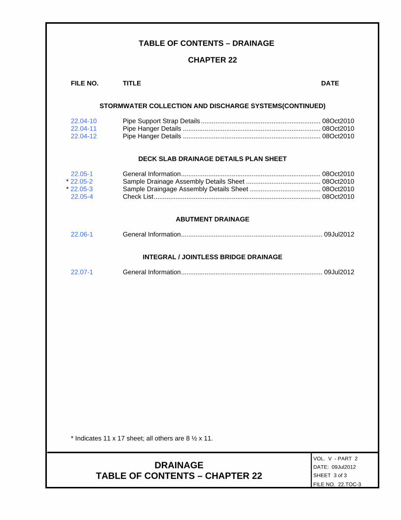
STORMWATER COLLECTION AND DISCHARGE SYSTEMS(CONTINUED) 22.04-10 Pipe Support Strap Details .................................................................. 08Oct2010 22.04-11 Pipe Hanger Details ............................................................................ 08Oct2010 22.04-12 Pipe Hanger Details ............................................................................ 08Oct2010
DECK SLAB DRAINAGE DETAILS PLAN SHEET 22.05-1 General Information ............................................................................. 08Oct2010
* 22.05-2 Sample Drainage Assembly Details Sheet ......................................... 08Oct2010 * 22.05-3 Sample Draingage Assembly Details Sheet ....................................... 08Oct2010
22.05-4 Check List ............................................................................................ 08Oct2010
ABUTMENT DRAINAGE 22.06-1 General Information .............................................................................. 09Jul2012
INTEGRAL / JOINTLESS BRIDGE DRAINAGE 22.07-1 General Information .............................................................................. 09Jul2012 * Indicates 11 x 17 sheet; all others are 8 ½ x 11.

VOL. V - PART 2
DATE: 08Oct2010
SHEET 1 of 1
DRAINAGE INTRODUCTION - CHAPTER 22
FILE NO. 22.00-1
INTRODUCTION It is the intent of this chapter to establish the guidelines, procedures and practices of the Structure and Bridge Division for the design of bridge drainage systems. It also provides design aids and other sources of information along with cross references to other Manuals of the Structure and Bridge Division (Volume V - series) to assist in the design and preparation of plans. The practices and specific requirements contained in this chapter have been established based on the Structure and Bridge Division’s experience, industry standards and recommendations. The practices and requirements set forth herein are intended to supplement or clarify the requirements of the AASHTO Standard and LRFD specifications In the event of conflict(s) between the practices and requirements set forth herein and those contained in the AASHTO Standard or LRFD specifications, the more stringent requirements shall govern. This chapter in the manual contains specific requirements and/or guidelines for the detailing of various components of the bridge drainage system. It is not the intent of these requirements and guidelines to supercede the requirements contained in Chapter 1 of this manual but to convey necessary information to the designer for the detailing of various components of the bridge drainage system. It is expected that the users of this chapter will adhere to the practices and requirements stated herein. NOTE: Due to various restrictions on placing files in this manual onto the Internet, portions of the drawings shown do not necessarily reflect the correct line weights, line types, fonts, arrowheads, etc. Wherever discrepancies occur, the written text shall take precedence over any of the drawn views.

VOL. V - PART 2
DATE: 08Oct2010
SHEET 1 of 14
DRAINAGE DECK SLAB DRAINAGE
GENERAL INFORMATION FILE NO. 22.01-1
GENERAL INFORMATION: This section establishes the practices, procedures and guidelines for the design of bridge deck slab drainage systems. The practices, procedures and guidelines contained in this section for the design of bridge drainage systems require routine maintenance to function properly. Sources of information utilitized in the development of this section are as follows:
• Federal Highway Administration, “Design of Bridge Deck Drainage,” Hydraulic Engineering
Circular No. 21, May 1993. • Virginia Department of Transportation, “Drainage Manual,” April 2002.
The bridge drainage systems covered in this section includes the bridge deck gutter, drainage inlets, downspouts and longitudinal stormwater drain pipes suspended under the deck slab. The primary goal in the design of the bridge deck slab drainage system is to limit the amount of stormwater runoff flowing on the travelway or ponding at sag (low) points in the roadway grade to quantities that will provide reasonable safety for the passage of vehicle traffic, as well as bicycle and pedestrian traffic. This shall be accomplished by:
• Placing drainage inlets at such points and at such intervals to intercept flows and control
spread of water on travel lanes. • Providing an adequately sized stormwater collection system, when required, to convey flow
from drainage inlets to a suitable outfall location. The bridge drainage system requirements shall be established and coordinated with the development of the bridge design during the Preliminary Engineering Phase I of the project in order to avoid conflict(s) with the structural components of the bridge.

VOL. V - PART 2
DATE: 08Oct2010
SHEET 2 of 14
DRAINAGE DECK SLAB DRAINAGE
HYDROLOGY / OPEN CHANNEL HYDRAULICS FILE NO. 22.01-2
HYDROLOGY / OPEN CHANNEL HYDRAULICS: Hydrology: There are many hydrologic methods available for estimating the peak stormwater runoff rate or discharge. The method recommended for the design of deck slab drainage system shall be the Rational Method. The design peak stormwater runoff rate for the deck slab drainage system can be computed by using the following equation:
Q = AiCk ××× where Q = design storm peak runoff rate (ft3/sec)
k = 1.0 = unit conversion factor C = 0.9 = a dimensionless runoff coefficient i = average rainfall intensity (in/hr) A = contributing drainage area (acres)
Open Channel Hydraulics: A bridge deck gutter is defined as the section of deck slab next to a parapet or railing curb that conveys water during a storm runoff event. Gutter cross sections are triangular in shape with the curb forming the near vertical leg of the triangle. See figure below.
DECK SLAB GUTTER SECTION The gutter flow rate in a triangular channel with a uniform cross slope can be computed by using the following modified Manning Equation:
Q = 67250671x
g TSSn
k ... ×××
where Q = gutter flow rate (ft3/sec)
gk = 0.56 = constant
VOL. V - PART 2
DATE: 08Oct2010
SHEET 3 of 14
DRAINAGE DECK SLAB DRAINAGE
HYDROLOGY / OPEN CHANNEL HYDRAULICS FILE NO. 22.01-3
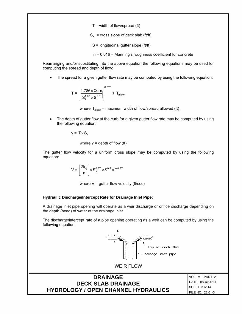
T = width of flow/spread (ft)
xS = cross slope of deck slab (ft/ft)
S = longitudinal gutter slope (ft/ft) n = 0.016 = Manning’s roughness coefficient for concrete
Rearranging and/or substituting into the above equation the following equations may be used for computing the spread and depth of flow:
• The spread for a given gutter flow rate may be computed by using the following equation:
T =
3750
50671x SS
nQ7861.
..
.
×
××≤ allowT
where allowT = maximum width of flow/spread allowed (ft)
• The depth of gutter flow at the curb for a given gutter flow rate may be computed by using
the following equation:
y = xST ×
where y = depth of flow (ft)
The gutter flow velocity for a uniform cross slope may be computed by using the following equation:
V = 67050670x
g TSSn
k2 ... ×××
where V = gutter flow velocity (ft/sec)
Hydraulic Discharge/Intercept Rate for Drainage Inlet Pipe: A drainage inlet pipe opening will operate as a weir discharge or orifice discharge depending on the depth (head) of water at the drainage inlet. The discharge/intercept rate of a pipe opening operating as a weir can be computed by using the following equation:
WEIR FLOW
VOL. V - PART 2
DATE: 08Oct2010
SHEET 4 of 14
DRAINAGE DECK SLAB DRAINAGE
HYDROLOGY / OPEN CHANNEL HYDRAULICS FILE NO. 22.01-4
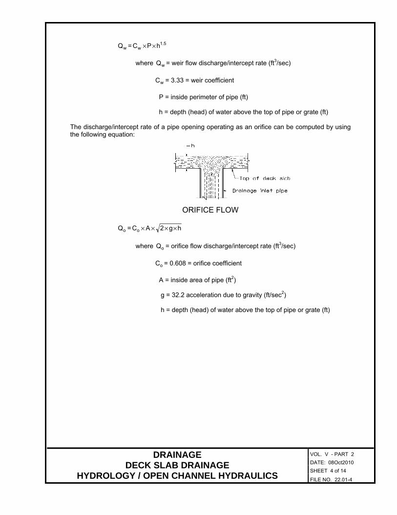
wQ = 51w hPC .××
where wQ = weir flow discharge/intercept rate (ft3/sec)
wC = 3.33 = weir coefficient
P = inside perimeter of pipe (ft) h = depth (head) of water above the top of pipe or grate (ft)
The discharge/intercept rate of a pipe opening operating as an orifice can be computed by using the following equation:
ORIFICE FLOW
oQ = hg2ACo ××××
where oQ = orifice flow discharge/intercept rate (ft3/sec)
oC = 0.608 = orifice coefficient
A = inside area of pipe (ft2) g = 32.2 acceleration due to gravity (ft/sec2) h = depth (head) of water above the top of pipe or grate (ft)

VOL. V - PART 2
DATE: 08Oct2010
SHEET 5 of 14
DRAINAGE DECK SLAB DRAINAGE
DECK SLAB DRAINAGE INLET HYDRAULICS FILE NO. 22.01-5
DECK SLAB DRAINAGE INLET HYDRAULICS: General: The two types of drainage inlets used by the Structure and Bridge Division for deck slab drainage are as follows:
• Downspout drainage inlets
• Grate drainage inlets For drainage inlet details, see File No. 22.03. The type of drainage inlet recommended for use when drainage inlets are required is the grate drainage inlet as it has a higher interception capacity and efficiency than the downspout drainage inlet. The downspout drainage inlet may be appropriate for use at sag (low) points and as flanking drainage inlets to discharge any water from the bridge deck slab. When drainage inlets are required, grate and downspout inlets on grade shall be located outside travel lanes to minimize the shifting of vehicles attempting to avoid these areas. All grate drainage inlets shall be bicycle safe when used at locations where bicycle travel is anticipated. For specific requirements for bicycle traffic, see File Nos. 06.04-1 thru -16. Drainage Inlet Interception Capacity and Efficiency: Frontal flow as referred to in this section is defined as the water flowing in the section of gutter (cross-hatched area) occupied by the drainage inlet as shown below.
GUTTER SECTION FOR DOWNSPOUT DRAINAGE INLET

VOL. V - PART 2
DATE: 08Oct2010
SHEET 6 of 14
DRAINAGE DECK SLAB DRAINAGE
DECK SLAB DRAINAGE INLET HYDRAULICS FILE NO. 22.01-6
GUTTER SECTION FOR GRATE DRAINAGE INLET The interception capacity of a drainage inlet is the amount of total approach frontal flow intercepted by the inlet. The interception capacity of an inlet changes with variations in cross slope, longitudinal slope and total gutter flow. Gutter flow entering a drainage inlet will act in one of the following states:
• Channel frontal flow
• Weir flow
• Orifice flow The amount of gutter flow discharged/intercepted by the drain inlet, InterceptQ , is assumed to be
the lesser of the above three calculated flow states. For Channel frontal flow intercepted by inlet, the following equations are used:
Gutter flow velocity (ft/sec) = V = 0.6750670x
g TSSn
k2×××
..
HYDRAULIC JUMP

VOL. V - PART 2
DATE: 08Oct2010
SHEET 7 of 14
DRAINAGE DECK SLAB DRAINAGE
DECK SLAB DRAINAGE INLET HYDRAULICS FILE NO. 22.01-7
Length of hydraulic jump (ft) = jumpL = ( ) 50dy2
V .+×
where V = gutter flow velocity (ft/sec)
y = xST × = depth of flow at curb (ft)
d = depth of deck slab depression (ft) T = width of flow/spread (ft)
xS = cross slope of deck slab (ft/ft)
Intercept factor = I.F. = jump
djump
L
wL −
where jumpL = length of jump (ft)
dw = inside width of grate drainage inlet or inside
diameter of downspout drainage inlet (ft) % channel frontal flow intercepted by drainage inlet = oE = 1.0 (for I.F. ≤ 0)
= 1.0 – I.F. (for I.F. > 0)
channelQ = ( )( ) ( )( )( )[ ]
oxdxd E
2
SXLySXyLV ×
×+−+×−××
where channelQ = channel frontal flow intercepted by drainage inlet (ft3/sec)
dL = inside length of grate drainage inlet or inside diameter of
downspout drainage inlet (ft) X = drain inlet offset from face of curb (ft)
oE = amount of channel frontal flow intercepted

VOL. V - PART 2
DATE: 08Oct2010
SHEET 8 of 14
DRAINAGE DECK SLAB DRAINAGE
DECK SLAB DRAINAGE INLET HYDRAULICS FILE NO. 22.01-8
For weir flow intercepted by drainage inlets, the following equation is used:
( )[ ]xw SXy333Q ×−×= . 1.5 D×π×
where wQ = weir flow intercept rate (ft3/sec)
D = inside diameter of pipe (ft) y = depth of flow (ft) X = drain inlet offset from face of curb (ft)
= 0 (for drainage inlets on flat or nearly flat grades ≤ 0.3%)
xS = cross slope of deck slab (ft/ft)
For orifice flow intercepted by drainage inlets, the following equation is used:
( )( )[ ]x
2
o SXyg24
D6080Q ×−×××
×π×= . 0.5
where oQ = orifice flow intercept rate (ft3/sec)
D = inside diameter of pipe (ft) g = 32.2 = acceleration due to gravity (ft/sec2) y = depth of flow (ft) X = drain inlet offset from face of curb (ft)
= 0 (for drainage inlets on flat or nearly flat grades)
xS = cross slope of deck slab (ft/ft)
The efficiency of a drainage inlet is the percent of total gutter approach flow the inlet will intercept which can be expressed by the following equation:
Total
Intercept
Q
QE =
where E = inlet interception efficiency (%)
InterceptQ = amount of flow intercepted by the drainage inlet (ft3/sec)
TotalQ = total approach frontal flow to the drainage inlet (ft3/sec)

VOL. V - PART 2
DATE: 08Oct2010
SHEET 9 of 14
DRAINAGE DECK SLAB DRAINAGE
DESIGN OF DECK SLAB DRAINAGE SYSTEM FILE NO. 22.01-9
DESIGN OF DECK SLAB DRAINAGE SYSTEM: General: All approach flow to and beyond the bridge is the responsibility of the road designer. The designer shall coordinate with the road designer to ensure that any flow off the bridge is accounted for in the roadway drainage design. General Design Procedure: The general procedure for designing the bridge drainage system involves establishing the following:
• Allowable spread and rainfall intensity for the bridge
• Layout of design sections for bridge
• Drainage inlet requirements and locations (spacings) when required
• Stormwater discharge and collection requirements.
It is assumed that all drainage inlets will have by-pass flow. The by-pass flow, pass-ByQ , is given
by the following equation:
pass-ByQ = Intercept1,2,...i QQ −= = ( )E01Q 1,2,...i −×= .
where pass-ByQ = by-pass flow at inlet (i=1,2,…) (ft3/sec)
1,2,...iQ = = total approach flow to the inlet (ft3/sec)
InterceptQ = amount of flow intercepted by inlet (i= 1,2,…) (ft3/sec)
= EQ 1,2,...i ×=
E = inlet interception efficiency (%)
Maximum Design Spread Width and Rainfall Intensities: The maximum design spread width (allowable), Tallow, is the maximum width of water allowed to accumulate on the bridge deck slab gutter before any drainage inlets are required. The rainfall intensity, i, is the average rate of rainfall (in/hr) for a selected duration (time of concentration) and design storm frequency for the locality in which the bridge is designed.

DRAINAGE DECK SLAB DRAINAGE
DESIGN OF DECK SLAB DRAINAGE SYSTEM
VOL. V - PART 2
DATE: 26Sept2012
SHEET 10 of 14
FILE NO. 22.01-10
The table below gives the design storm frequency, intensity and maximum design spread width (allowable) for different roadway classifications, vertical alignment and design speed.
DESIGN STORM FREQUENCY, INTENSITY AND SPREAD
Roadway Classification
Design Speed
Design Storm Maximum Design Spread Width Frequency Intensity
(mph) (year) (in/hr) (ft)
Freeways (Interstate):
On Grade ALL 10 *Actual Shoulder width w/ no encroachment in traffic lane
At Sag Point ALL 50 *Actual Shoulder width w/ no encroachment in traffic lane
Principal Arterial:
On Grade ≤ 50 10 4.0 Shoulder/gutter width plus 1/2 traffic lane encroachment
> 50 10 *Actual Shoulder/gutter width plus 3’-0” encroachment in traffic lane
At Sag Point ≤ 50 10 4.0 Shoulder/gutter width plus 1/2 traffic lane encroachment
> 50 50 *Actual Shoulder/gutter width plus 3’-0” encroachment in traffic lane
Minor Arterial, Collector and Local:
On Grade ≤ 50 10 4.0 Shoulder/gutter width plus 1/2 traffic lane encroachment
> 50 10 4.0 Shoulder/gutter width plus 3’-0” encroachment in traffic lane
At Sag Point ≤ 50 10 4.0 Shoulder/gutter width plus 1/2 traffic lane encroachment
> 50 50 4.0 Shoulder/gutter width plus 3’-0” encroachment in traffic lane For superelevated bridge deck slabs, the depth of water flow at edge of traffic lane shall be limited to 3” maximum. The maximum design spread width for areas designated for use by pedestrian and/or bicycle traffic shall be one-half the “clear width of pedestrian and/or bicycle facility.”
* When the above table notes “Actual” for intensity, the designer shall contact L&D Hydraulics for the actual rainfall intensity at the bridge location. In no case shall the rainfall intensity be less than 4.0 in/hr. Layout of Bridge Design Sections: Bridges with single vertical profile alignments have only one design section for bridges on a gradient (tangent) and two design sections for bridges on a vertical curve. Bridges with multiple vertical profile alignments shall be broken down into design sections as shown below. The first step is locating the PVC and PVT for all vertical curves on the bridge and to identify any tangent sections. Tangent sections and vertical curve sections shall be separated for drainage design calculations.

VOL. V - PART 2
DATE: 08Oct2010
SHEET 11 of 14
DRAINAGE DECK SLAB DRAINAGE
DESIGN OF DECK SLAB DRAINAGE SYSTEM FILE NO. 22.01-11
BRIDGE VERTICAL ALIGNMENT Locate the high end for bridges on a gradient (tangent). Locate high point and/or sag (low) point for bridges on vertical curve alignments. The location of high/sag (low) points on vertical curves can be determined by using the following equation:
Sta.High/Low Point = Sta.PVC + 21
1
gg
LVCg
−
×
where
1g = slope of the tangent through the PVC (%)
2g = slope of the tangent through the PVT (%)
LVC = length of vertical curve (ft)
Number the design sections from the high point (starting point for calculation of spacings) to the left and then from the high point to the right. General Drainage Inlet Requirements and Locations (Spacing): Drainage inlets shall be provided and located to limit the spread of water on the travel lanes in accordance with the drainage design requirements specified in File No. 22.01-10. A drainage inlet shall be provided at all sag (low) points regardless of the hydraulic requirements for the bridge and a minimum of one flanking drainage inlet at a 5’-0” maximum spacing shall be provided on each side. This is to limit the spread of water and to act in relief of the sag (low) point drainage inlet should it become clogged or the design storm is exceeded. Transition areas, especially in areas from a crowned section to a superelevated section, require additional analysis beyond the scope of this manual. In general, elevations may need to be adjusted so that flat areas and irregularities can be adjusted to form a smooth grade. One method is to plot curb elevations on a reasonable vertical scale every two to five feet. The flat spots and irregularities can be adjusted by introducing a spline grade to achieve a smooth grade. A drainage inlet spacing of five feet (+/-) through these areas is recommended to prevent ponding of water especially in areas subject to icing.

VOL. V - PART 2
DATE: 08Oct2010
SHEET 12 of 14
DRAINAGE DECK SLAB DRAINAGE
DESIGN OF DECK SLAB DRAINAGE SYSTEM FILE NO. 22.01-12
The procedure for determining drainage inlet requirements and locations (spacing) for bridges on a gradient (tangent) starts at the high end of the bridge with the computation of the distance to the first required inlet. The spacing of remaining down grade inlets when required, continues until the end of the bridge is reached. The procedure for determining drainage inlet requirements and locations (spacing) for bridges on a vertical curve starts at the high point(s) on the bridge with the computation of the distance to the first required inlet. The spacing of remaining down grade inlets when required, continues until the end of bridge or the sag (low) point is reached. The general procedure for determining drainage inlet requirements and locations (spacings) are as follows:
• Determine the location of the first required drainage inlet from the high end/point on the bridge or design section
• Determine drainage inlet efficiency and capacity (See File Nos. 22.01-5 thru -8)
• Compute spacing between down grade drainage inlets considering discharge requirements and span arrangement
• Adjust drainage inlet spacings as necessary to avoid conflicts with structural components of the bridge
Drainage Inlet Locations (Spacing) for Bridges/Design Sections on a Gradient (Tangent): The distance, 1iL = , from the high end/point on the bridge/design section to the first required
drainage inlet location can be computed by using the following equation:
1iL = = p
max
2
WiC
Qacre
ft43560
××
×
where 1iL = = distance from high end or point on the bridge to first drainage
inlet (ft)
maxQ = 1iQ = = maximum gutter flow allowed (ft3/sec)
= 2.67allow
50671x
g TSSn
k×××
..
The distance, 1iL = , computed by using the above equation is then compared with the length of
bridge or the length of long/short end of the bridge or the length of the design section.
• If 1iL = > length of bridge or long/short end of bridge or the length of the design section,
then drainage inlets are not required.
• If 1iL = < length of bridge or long/short end of bridge or the length of the design section,
then drainage inlets are required.

VOL. V - PART 2
DATE: 08Oct2010
SHEET 13 of 14
DRAINAGE DECK SLAB DRAINAGE
DESIGN OF DECK SLAB DRAINAGE SYSTEM FILE NO. 22.01-13
When drainage inlets are required, the spacing between remaining down grade drainage inlets,
2,3...iL = , can be computed using the following equation:
2,3...iL = = ( )
p
pass-Bymax
2
WiC
QQacre
ft43560
××
−×
where maxQ = maximum gutter flow allowed (ft3/sec)
= 2.67allow
50671x
g TSSn
k×××
..
pass-ByQ = by-pass flow from up grade inlet (ft3/sec)
The actual gutter flow, 2...1iQ ,= ,approaching a drainage inlet is computed using the following
equation:
2...1iQ ,= =
acre
ft43560
LWiC
2
2...1ip ,=×××+ pass-ByQ ≤ maxQ
where pass-ByQ = by-pass flow from up grade inlet (ft3/sec)
= 0 (for Drain #1 - no by-pass from up grade drainage
inlet) Drainage Inlet Locations (Spacing) for Bridges/Design Sections on a Vertical Curve: The methodology used for determining the drainage inlet locations (spacing) for bridges/design sections on vertical curves is similar to that for bridges/design sections on a gradient (tangent) except a trial and error approach is necessary to take into account changes in gutter slope from one inlet to another. A trial distance 1,2,...iL = to the inlet is selected and the gutter slope at this location is computed
using the following equation:
1,2...iS = = 1
12 gXLVC
gg+×
−
where 1,2...iS = = longitudinal gutter slope at the (i th) drainage inlet (use
absolute value) (ft/ft) LVC = length of vertical curve (ft)
1
g = slope of the tangent though the PVC (%)

VOL. V - PART 2
DATE: 08Oct2010
SHEET 14 of 14
DRAINAGE DECK SLAB DRAINAGE
DESIGN OF DECK SLAB DRAINAGE SYSTEM FILE NO. 22.01-14
2
g = slope of the tangent though the PVT (%)
X = distance from the PVC to the location of the (i th) drainage
inlet (ft) The maximum allowed gutter flow is then computed using the gutter slope determined by the above equation. The maximum allowed gutter flow and by-pass flow (from up grade inlet) is used in the appropriate equations given for bridges/design sections on a gradient (tangent) to compute the distance to the inlet and the actual gutter flow for the trial distance. If the computed distance to the inlet is less than the trial distance and/or if the computed actual gutter flow is greater than the maximum gutter flow, then select another trial distance and repeat the computations. See Sample Deck Slab Drainage Design in File Nos. 22.02-1 thru -12. Drainage Inlet Requirements and Locations (Spacing) for Flat or Nearly Flat Bridges/Design Sections: Bridges/design sections on gradient (tangent) or vertical curves having sag (low) points or points along the vertical curve where the longitudinal gutter slope is less than or equal to 0.003 ft/ft shall be assumed flat or nearly flat for purposes of determining locations (spacing) of drainage inlets. Gutter flow entering a drainage inlet will act in one of the following states:
• Weir flow
• Orifice flow For determining the amount of flow intercepted by the drainage inlets, InterceptQ shall be the lesser
of the above flows. The number of drainage inlets required can be computed by using the following equation:
N = Intercept
Total
Q
Q
where N = minimum number of drainage inlets required
TotalQ = total flow (ft3/sec)
= 43560
LWiC p ××× + pass-ByQ
L = distance between up grade inlet(s) (ft)
InterceptQ = amount of flow intercepted by the drainage inlet (ft3/sec)
pass-ByQ = sum of the by-pass flows from up grade inlets (ft3/sec)
VOL. V - PART 2
DATE: 08Oct2010
SHEET 1 of 13
DRAINAGE DECK SLAB DRAINAGE DESIGN
SAMPLE DESIGN CALCULATIONS FILE NO. 22.02-1
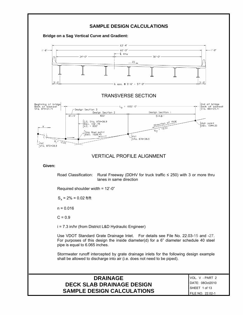
SAMPLE DESIGN CALCULATIONS Bridge on a Sag Vertical Curve and Gradient:
TRANSVERSE SECTION
VERTICAL PROFILE ALIGNMENT Given:
Road Classification: Rural Freeway (DDHV for truck traffic ≤ 250) with 3 or more thru
lanes in same direction Required shoulder width = 12’-0”
xS = 2% = 0.02 ft/ft
n = 0.016 C = 0.9 i = 7.3 in/hr (from District L&D Hydraulic Engineer) Use VDOT Standard Grate Drainage Inlet. For details see File No. 22.03-15 and -27. For purposes of this design the inside diameter(d) for a 6” diameter schedule 40 steel pipe is equal to 6.065 inches. Stormwater runoff intercepted by grate drainage inlets for the following design example shall be allowed to discharge into air (i.e. does not need to be piped).

VOL. V - PART 2
DATE: 08Oct2010
SHEET 2 of 13
DRAINAGE DECK SLAB DRAINAGE DESIGN
SAMPLE DESIGN CALCULATIONS FILE NO. 22.02-2
Design Criteria: The allowable spread for a Freeway (Interstate) is as follows:
allowT = shoulder width with no encroachment = 12”-0”
The width of deck slab contributing runoff is computed as follows:
PW = ft060
ft
in12
in8754in2522 ... +
+× = 61.19 ft
Design Section 1: Drain #1: Determine the spacing, 1L , from the high point in Design Section 1 to the first required drainage
inlet in Design Section 1:
Compute maximum gutter flow for an allowable spread, allowT = 12 ft:
With a longitudinal gutter slope, S = 0.025 ft/ft
maxQ = 1Q = 2.67allow
50671x
g TSSn
k×××
..
= ( ) 67250671
ft012ft
ft0250
ft
ft020
0160
560 ...
..... ×
×
×
= 6.13 ft3/sec
From the high point in Design Section 1, the distance to the first required drainage inlet:
1L = p
max
2
WiC
Qacre
ft43560
××
×=
ft1961hr
in7.30.9
sec
ft136
acre
ft43560
32
.
.
××
×= 664.2 ft
> length of Design Section 1 = 514.81 ft
Therefore, drainage inlets not required in Design Section 1 Design Section 2: Drain #1: Determine the spacing, 1L , from the high point in Design Section 1 to the first required drainage
inlet in Design Section 2:

VOL. V - PART 2
DATE: 08Oct2010
SHEET 3 of 13
DRAINAGE DECK SLAB DRAINAGE DESIGN
SAMPLE DESIGN CALCULATIONS FILE NO. 22.02-3
Assume a trial distance of 1L = 700 ft:
Therefore, the distance from the PVC of the curve to this location is as follows:
X = 800 ft - (700 ft - 514.81 ft) = 614.81 ft from the PVC
and the slope at “X” is computed as follows:
S = 1
12 gXLVC
gg+×
−=
ft
ft0250ft81614
ft800ft
ft0250
ft
ft0.025
...
−×
+ = 0.0134 ft/ft
Compute maximum gutter flow for an allowable spread, allowT = 12 ft:
maxQ = 1iQ = = 2.67allow
50671x
g TSSn
k×××
..
maxQ = 1iQ = ( ) 67250671
ft012ft
ft01340
ft
ft020
0160
560 ...
..... ×
×
×
= 4.48 ft3/sec
The distance from high point in Design Section 1 to the first drainage inlet, 1L , in Design
Section 2 is computed as follows:
1L = p
max
2
WiC
Qacre
ft43560
××
×=
ft1961hr
in7.30.9
sec
ft484
acre
ft43560
32
.
.
××
× = 485 ft ≠ trial 1L = 700 ft
Therefore, select a new trial value for L1 and repeat the above steps Assume a second trial distance of 1L = 590 ft:
Therefore, the distance from the PVC of the curve to this location is as follows:
X = 800 ft - (590 ft - 514.81 ft) = 724.81 ft from the PVC
and the slope at “X” is computed as follows:
S = 1
12 gXLVC
gg+×
−=
ft
ft0250ft81724
ft800ft
ft0250
ft
ft0.025
...
−×
+ = 0.0203 ft/ft
Compute maximum gutter flow for an allowable spread, allowT = 12 ft:
maxQ = 1iQ = = 2.67allow
50671x
g TSSn
k×××
..
maxQ = 1iQ = = ( ) ( ) 67250671
ft01202030ft
ft020
0160
560 ...
..... ××
×
= 5.52 ft3/sec

VOL. V - PART 2
DATE: 08Oct2010
SHEET 4 of 13
DRAINAGE DECK SLAB DRAINAGE DESIGN
SAMPLE DESIGN CALCULATIONS FILE NO. 22.02-4
The distance from high point in Design Section 1 to the first drainage inlet, 1L , in Design
Section 2 is computed as follows:
1L = p
1
2
WiC
Qacre
ft43560
××
×=
ft1961hr
in7.30.9
sec
ft525
acre
ft43560
32
.
.
××
× = 598 ft ≈ trial 1L =590 ft OK
The actual gutter flow, 1Q (act), approaching Drain #1 is computed as follows:
1Q (act) =
acre
ft43560
LWiC
2
1p ×××=
acre
ft43560
ft590ft1961hr
in3790
2
××× ...= 5.45 ft3/sec
< maxQ =5.52 ft3/sec OK
Therefore, use 1L = 590 ft from the high point in Design Section 1
Determine inlet interception efficiency and by-pass flow for Drain #1: • Channel Flow:
Actual spread = actT =
3750
50671x
1
SS
nactQ7861.
..
)(.
×
××=
3750
0.51.67
3
ft
ft02030
ft
ft020
0160sec
ft4557861
.
..
...
×
××
= 11.98 ft
Gutter flow velocity = V = 0.67act
50670x
g TSSn
k2×××
..
= ( ) 670500.67
ft9811ft
ft02030
ft
ft020
0160
5602 ..
....
. ×
×
×
×
= 3.83 ft/sec
Depth of flow at curb = y = xSTact × = ft
ft020ft9811 .. × = 0.24 ft
Length of hydraulic jump = jumpL = ( ) 50dy2
V .+× =
50
ft
in12
in50ft240
2sec
ft3.83
.
..
+× = 1.02 ft
with a width of drain = dw = ( )
ft
in12
in7502in138 .. ×−= 0.55 ft
VOL. V - PART 2
DATE: 08Oct2010
SHEET 5 of 13
DRAINAGE DECK SLAB DRAINAGE DESIGN
SAMPLE DESIGN CALCULATIONS FILE NO. 22.02-5
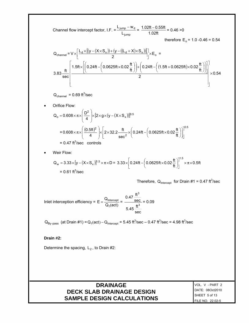
Channel flow intercept factor, I.F. =jump
djump
L
wL −=
ft021
ft550ft021
... −
= 0.46 >0
therefore oE = 1.0 -0.46 = 0.54
channelQ =( )( ) ( )( )( )[ ]
oxdxd E
2
SXLySXyLV ×
×+−+×−×× =
( )540
2
ft
ft020ft06250ft51ft240
ft
ft020ft06250ft2401.5ft
sec
ft3.83 .
.......×
×+−+
×−×
channelQ = 0.69 ft3/sec
• Orifice Flow:
( )( )[ ] 50x
2
o SXyg24
D6080Q .. ×−×××
×π×=
=( ) 50
2
2
ft
ft020ft06250ft240
sec
ft2322
4
ft506080
.
......
×−×××
×π×
= 0.47 ft3/sec controls
• Weir Flow:
( )[ ] DSXy333Q 51xw ×π××−×= .. = ft50
ft
ft020ft06250ft240333
51
......
×π×
×−×
= 0.61 ft3/sec
Therefore, InterceptQ for Drain #1 = 0.47 ft3/sec
Inlet interception efficiency = )(actQ
QE
1
Intercept= =
sec
ft5.45
sec
ft0.47
3
3
= 0.09
pass-ByQ (at Drain #1) = Intercept1 QactQ −)( = 5.45 ft3/sec – 0.47 ft3/sec = 4.98 ft3/sec
Drain #2: Determine the spacing, 2L , to Drain #2:
VOL. V - PART 2
DATE: 08Oct2010
SHEET 6 of 13
DRAINAGE DECK SLAB DRAINAGE DESIGN
SAMPLE DESIGN CALCULATIONS FILE NO. 22.02-6
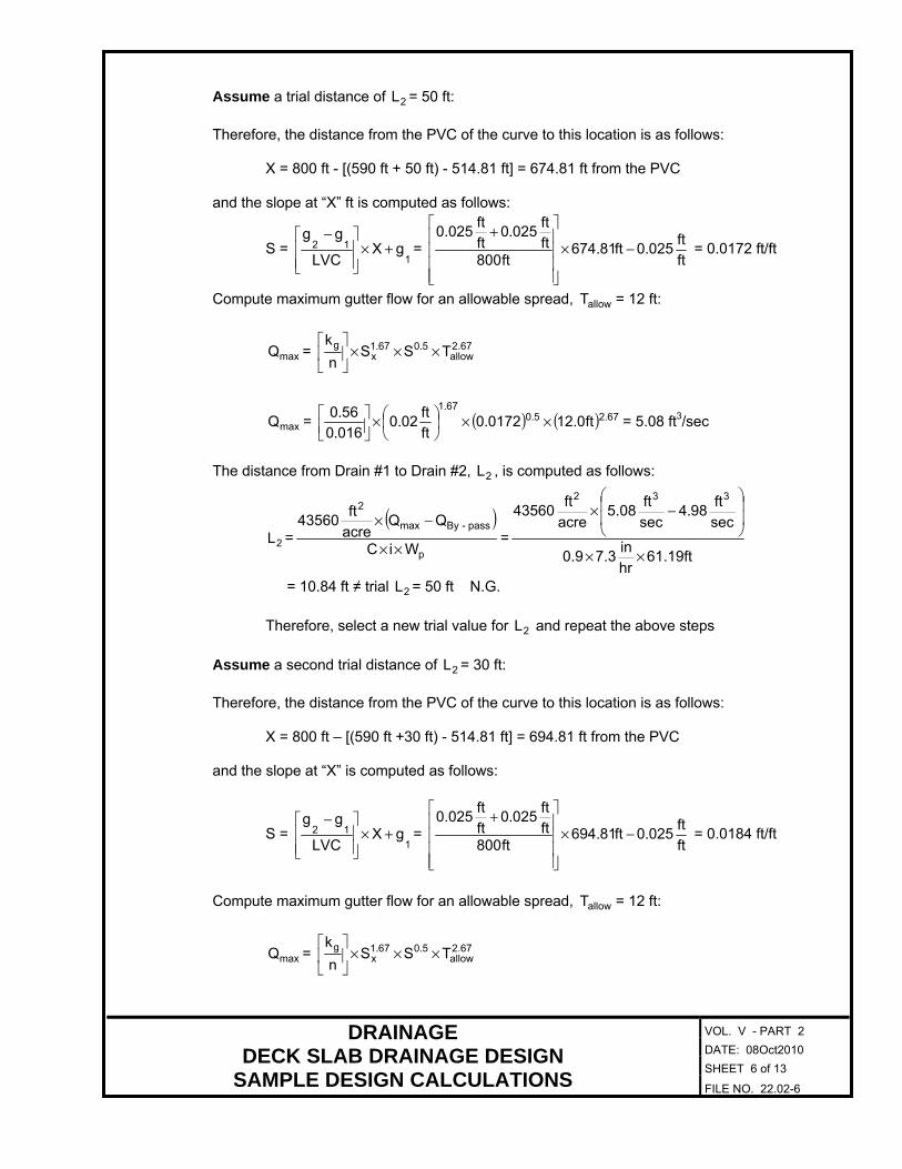
Assume a trial distance of 2L = 50 ft:
Therefore, the distance from the PVC of the curve to this location is as follows:
X = 800 ft - [(590 ft + 50 ft) - 514.81 ft] = 674.81 ft from the PVC
and the slope at “X” ft is computed as follows:
S = 1
12 gXLVC
gg+×
−=
ft
ft0250ft81674
ft800ft
ft0250
ft
ft0.025
...
−×
+ = 0.0172 ft/ft
Compute maximum gutter flow for an allowable spread, allowT = 12 ft:
maxQ = 2.67allow
50671x
g TSSn
k×××
..
maxQ = ( ) ( ) 67250671
ft01201720ft
ft020
0160
560 ...
..... ××
×
= 5.08 ft3/sec
The distance from Drain #1 to Drain #2, 2L , is computed as follows:
2L =( )
p
pass-Bymax
2
WiC
QQacre
ft43560
××
−×=
61.19fthr
in7.30.9
sec
ft984
sec
ft5.08
acre
ft43560
332
××
−× .
= 10.84 ft ≠ trial 2L = 50 ft N.G.
Therefore, select a new trial value for 2L and repeat the above steps
Assume a second trial distance of 2L = 30 ft:
Therefore, the distance from the PVC of the curve to this location is as follows:
X = 800 ft – [(590 ft +30 ft) - 514.81 ft] = 694.81 ft from the PVC
and the slope at “X” is computed as follows:
S = 1
12 gXLVC
gg+×
−=
ft
ft0250ft81694
ft800ft
ft0250
ft
ft0.025
...
−×
+ = 0.0184 ft/ft
Compute maximum gutter flow for an allowable spread, allowT = 12 ft:
maxQ = 2.67allow
50671x
g TSSn
k×××
..

VOL. V - PART 2
DATE: 08Oct2010
SHEET 7 of 13
DRAINAGE DECK SLAB DRAINAGE DESIGN
SAMPLE DESIGN CALCULATIONS FILE NO. 22.02-7
maxQ = ( ) ( ) 67250671
ft01201840ft
ft020
0160
560 ...
..... ××
×
= 5.26 ft3/sec
The distance from Drain #1 to Drain #2, 2L , is computed as follows:
2L =( )
p
pass-Bymax
2
WiC
QQacre
ft43560
××
−×=
61.19fthr
in7.30.9
sec
ft984
sec
ft5.26
acre
ft43560
332
××
−× .
= 30.34 ft ≈ trial 2L = 30 ft OK
The actual gutter flow, 2Q (act), approaching Drain #2 is computed as follows:
2Q (act) =
acre
ft43560
LWiC
2
2p ××× + pass-ByQ =
acre
ft43560
ft30ft1961hr
in3790
2
××× ... + 4.98 ft3/sec
= 5.26 ft3/sec = maxQ = 5.26 ft3/sec OK
Therefore, use 2L = 30 ft from Drain #1
Determine inlet interception efficiency and by-pass flow for Drain #2 • Channel Flow:
Actual spread = actT =
3750
50671x
2
SS
nactQ7861.
..
)(.
×
××=
3750
0.51.67
3
ft
ft01840
ft
ft020
0160sec
ft2657861
.
..
...
×
××
= 12.04 ft
Gutter flow velocity = V = 0.67act
50670x
g TSSn
k2×××
..
= ( ) 670500.67
ft0412ft
ft01840
ft
ft020
0160
5602 ..
....
. ×
×
×
×
= 3.66 ft/sec
Depth of flow at curb = y = xact ST × = ft
ft020ft0412 .. × = 0.24 ft
Length of hydraulic jump = jumpL = ( ) 50dy2
V .+× =
50
ft
in12
in50ft240
2sec
ft3.66
.
..
+× = 0.97 ft
VOL. V - PART 2
DATE: 08Oct2010
SHEET 8 of 13
DRAINAGE DECK SLAB DRAINAGE DESIGN
SAMPLE DESIGN CALCULATIONS FILE NO. 22.02-8
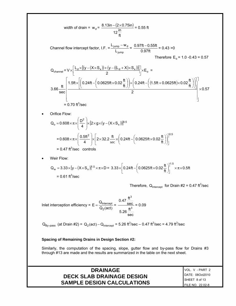
width of drain = dw = ( )
ft
in12
in7502in138 .. ×−= 0.55 ft
Channel flow intercept factor, I.F. =jump
djump
L
wL −=
ft970
ft550ft970
... −
= 0.43 >0
Therefore oE = 1.0 -0.43 = 0.57
channelQ =( )( ) ( )( )( )[ ]
oxdxd E
2
SXLySXyLV ×
×+−+×−×× =
( )570
2
ft
ft020ft06250ft51ft240
ft
ft020ft06250ft2401.5ft
sec
ft3.66 .
.......×
×+−+
×−×
= 0.70 ft3/sec
• Orifice Flow:
( )( )[ ] 50x
2
o SXyg24
D6080Q .. ×−×××
×π×=
=502
ft
ft020ft06250ft240
ft2322
4
ft506080
.
...sec
...
×−×××
×π×
= 0.47 ft3/sec controls
• Weir Flow:
( )[ ] DSXy333Q 51xw ×π××−×= .. = ft50
ft
ft020ft06250ft240333
51
......
×π×
×−×
= 0.61 ft3/sec
Therefore, InterceptQ for Drain #2 = 0.47 ft3/sec
Inlet interception efficiency = )(actQ
QE
2
Intercept= =
sec
ft5.26
sec
ft0.47
3
3
= 0.09
pass-ByQ (at Drain #2) = Intercept2 QactQ −)( = 5.26 ft3/sec – 0.47 ft3/sec = 4.79 ft3/sec
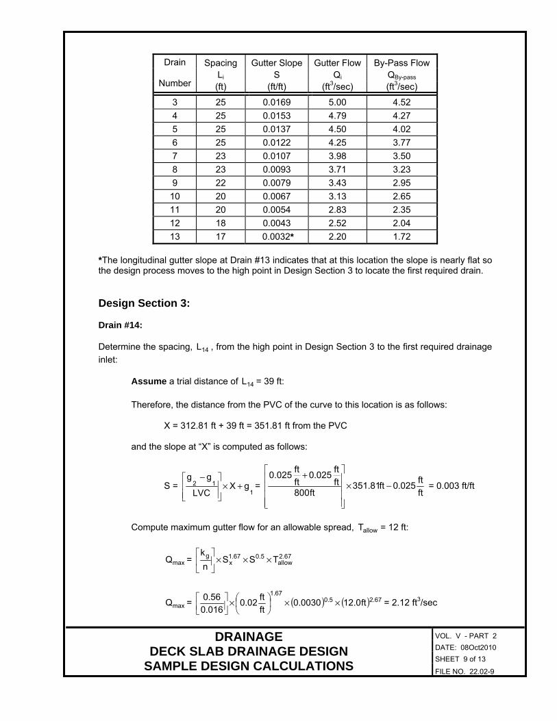
Spacing of Remaining Drains in Design Section #2: Similarly, the computation of the spacing, slope, gutter flow and by-pass flow for Drains #3 through #13 are made and the results are summarized in the table on the next sheet.
VOL. V - PART 2
DATE: 08Oct2010
SHEET 9 of 13
DRAINAGE DECK SLAB DRAINAGE DESIGN
SAMPLE DESIGN CALCULATIONS FILE NO. 22.02-9
Spacing Gutter Slope Gutter Flow By-Pass Flow Li S Qi QBy-pass
Drain
Number (ft) (ft/ft) (ft3/sec) (ft3/sec)
3 25 0.0169 5.00 4.52
4 25 0.0153 4.79 4.27
5 25 0.0137 4.50 4.02
6 25 0.0122 4.25 3.77
7 23 0.0107 3.98 3.50
8 23 0.0093 3.71 3.23
9 22 0.0079 3.43 2.95
10 20 0.0067 3.13 2.65
11 20 0.0054 2.83 2.35
12 18 0.0043 2.52 2.04
13 17 0.0032* 2.20 1.72
*The longitudinal gutter slope at Drain #13 indicates that at this location the slope is nearly flat so the design process moves to the high point in Design Section 3 to locate the first required drain. Design Section 3: Drain #14: Determine the spacing, 14L , from the high point in Design Section 3 to the first required drainage
inlet:
Assume a trial distance of 14L = 39 ft:
Therefore, the distance from the PVC of the curve to this location is as follows:
X = 312.81 ft + 39 ft = 351.81 ft from the PVC
and the slope at “X” is computed as follows:
S = 1
12 gXLVC
gg+×
−=
ft
ft0250ft81351
ft800ft
ft0250
ft
ft0.025
...
−×
+ = 0.003 ft/ft
Compute maximum gutter flow for an allowable spread, allowT = 12 ft:
maxQ = 2.67allow
50671x
g TSSn
k×××
..
maxQ = ( ) ( ) 67250671
ft01200300ft
ft020
0160
560 ...
..... ××
×
= 2.12 ft3/sec

VOL. V - PART 2
DATE: 08Oct2010
SHEET 10 of 13
DRAINAGE DECK SLAB DRAINAGE DESIGN
SAMPLE DESIGN CALCULATIONS FILE NO. 22.02-10
The actual gutter flow, 14Q (act), approaching Drain #14 is computed as follows:
14Q (act) =
acre
ft43560
LWiC
2
14p ×××=
acre
ft43560
ft39ft1961hr
in3790
2
××× ...= 0.36 ft3/sec < maxQ
OK Since the slope at 14L is nearly flat (S ≤ 0.003 ft/ft), locate Drain #14 at a distance of
14L = 39 ft from the high point in Design Section 3.
Determine inlet interception efficiency and by-pass flow for Drain #14: • Channel Flow:
Actual spread = actT = ( )
3750
50671x
14
SS
nactQ7861.
..
.
×
××=
3750
0.51.67
3
ft
ft0030
ft
ft020
0160sec
ft3607861
.
..
...
×
××= 6.19 ft
Gutter flow velocity = V = 0.67act
50670x
g TSSn
k2×××
..
= ( ) 670500.67
ft196ft
ft00300
ft
ft020
0160
5602 ..
....
. ×
×
×
×
= 0.95 ft/sec
Depth of flow at curb = y = xact ST × = ft
ft020ft196 .. × = 0.12 ft
Length of hydraulic jump = jumpL = ( ) 50dy2
V .+× =
50
ft
in12
in50ft120
2sec
ft0.95
.
..
+× = 0.20 ft
with a width of drain = dw = ( )
ft
in12
in7502in138 .. ×−= 0.55 ft
Channel flow intercept factor, I.F. =jump
djump
L
wL −=
ft200
ft550ft200
... −
= -1.75 < 0
Therefore, oE = 1.0
VOL. V - PART 2
DATE: 08Oct2010
SHEET 11 of 13
DRAINAGE DECK SLAB DRAINAGE DESIGN
SAMPLE DESIGN CALCULATIONS FILE NO. 22.02-11
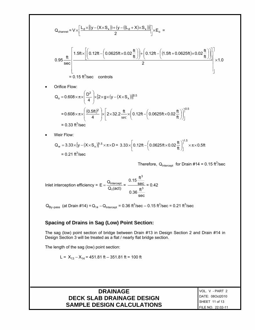
channelQ =( )( ) ( )( )( )[ ]
oxdxd E
2
SXLySXyLV ×
×+−+×−×× =
( )01
2
ft
ft020ft06250ft51ft120
ft
ft020ft06250ft1201.5ft
sec
ft0.95 .
.......×
×+−+
×−×
= 0.15 ft3/sec controls
• Orifice Flow:
( )( )[ ] 50x
2
o SXyg24
D6080Q .. ×−×××
×π×=
=( ) 502
ft
ft020ft06250ft120
ft2322
4
ft506080
.
...sec
...
×−×××
×π×
= 0.33 ft3/sec
• Weir Flow:
( )[ ] DSXy333Q 51xw ×π××−×= .. = ft50
ft
ft020ft06250ft120333
51
......
×π×
×−×
= 0.21 ft3/sec
Therefore, InterceptQ for Drain #14 = 0.15 ft3/sec
Inlet interception efficiency = )(actQ
QE
1
Intercept= =
sec
ft0.36
sec
ft0.15
3
3
= 0.42
pass-ByQ (at Drain #14) = Intercept14 QQ − = 0.36 ft3/sec – 0.15 ft3/sec = 0.21 ft3/sec
Spacing of Drains in Sag (Low) Point Section: The sag (low) point section of bridge between Drain #13 in Design Section 2 and Drain #14 in Design Section 3 will be treated as a flat / nearly flat bridge section. The length of the sag (low) point section:
L = 1413 XX − = 451.81 ft – 351.81 ft = 100 ft

VOL. V - PART 2
DATE: 08Oct2010
SHEET 12 of 13
DRAINAGE DECK SLAB DRAINAGE DESIGN
SAMPLE DESIGN CALCULATIONS FILE NO. 22.02-12
Sum of the by-pass flow from Drain #13 (Design Section #2) and Drain #14 (Design Section #3):
pass-ByQ (Total) = pass-ByQ (Drain #13) + pass-ByQ (Drain #14) = 1.72sec
ft3
+ 0.21sec
ft3
= 1.93sec
ft3
Total flow for this section of the bridge:
TotalQ =
acre
ft43560
LWiC
2
p ××× + pass-ByQ (Total) =
acre
ft43560
ft100ft1961hr
in3790
2
××× ... + 1.93
sec
ft3
= 2.85sec
ft3
Interception capacity per drainage inlet:
with allowT = 12 ft, the maximum depth of flow at curb is computed as follows:
maxy = xallow ST × = ft
ft020ft 12.0 .× = 0.24 ft
The intercept capacity per drain is the lesser of the following flow interception capacities: • Weir flow interception capacity:
wQ = Dy333 1.5max ×π××. = ft50ft240333 51 ... . ×π×× = 0.62
sec
ft3
• Orifice flow interception capacity:
oQ = [ ] 50
max
2
yg24
D6080
.. ×××
×π×
=( ) 502
ft240sec
ft2322
4
0.5ft6080
....
×××
×π× = 0.47
sec
ft3
controls
Therefore, interceptQ capacity per drain = 0.47 ft3/sec
The total number of drainage inlets required in this section is computed as follows:
N = Intercept
Total
Q
Q=
sec
ft0.47
sec
ft2.85
3
3
= 6.06 drains Therefore, use 7 drains

VOL. V - PART 2
DATE: 08Oct2010
SHEET 13 of 13
DRAINAGE DECK SLAB DRAINAGE DESIGN
SAMPLE DESIGN CALCULATIONS FILE NO. 22.02-13
DRAIN SPACING FOR SAG POINT SECTION
VOL. V - PART 2
DATE: 08Oct2010
SHEET 1 of 27
DRAINAGE DECK SLAB DRAINAGE INLET DETAILS
GENERAL INFORMATION FILE NO. 22.03-1
GENERAL INFORMATION: The deck slab drainage inlet details used by the Structure and Bridge Division are shown in this section of the chapter. The details shown are for the designer’s information only. See Introduction File No. 22.00-1. The minimum and maximum deck slab cantilever width requirements shown in this section for a drainage inlet detail are only intended to assist the designer in determining where the particular drainage inlet detail may be used. They are not intended to supercede the requirements for deck slab cantilevers contained in Chapter 10 of this manual. The deck slab drainage inlet details shown may not work for all locations as it is dependent on the location of face of curb/rail. The designer may need to adjust the deck slab cantilever width and or beam/girder spacings. When deck slab drainage inlets are required in locations designated for use by pedestrian and/or bicycle traffic, all downspout and grate openings shall be pedestrian and bicycle friendly and conform to the requirements of File No. 6.04 of this manual. The location(s) of deck slab drainage inlets shall be shown on the deck slab plan sheet of the bridge plans. Reinforcing steel in deck slab may be shifted or cut as directed by the Engineer to clear the downspout pipe or grate drainage assembly. Costs for furnishing and installing all components of the deck slab drainage system shall be included as a lump sum bid item as shown on the plans. MATERIALS: Steel pipe downspouts shall be ASTM A53 Schedule 40 black seamless steel pipe. Steel plates, bars and rods shall be ASTM A36. All bolts shall be ASTM A325. All threaded inserts shall be flared thin slab ferrule 1/2”- 9 NC threaded insert. See File No. 12.09-3. CORROSION PROTECTION: Welded frame, grate and downspout pipe assemblies and attachments to include all steel pipes, plates, bars, rods, studs, bolts and nuts shall be hot dipped galvanized after fabrication. When pipe support straps are attached to weathering steel, a neoprene or vinyl washer shall be placed between the contact surfaces of the support strap and the hex nut with the weathering steel to isolate the contact between the two surfaces.

VOL. V - PART 2
DATE: 08Oct2010
SHEET 2 of 27
DRAINAGE DECK SLAB DRAINAGE INLET DETAILS
DOWNSPOUT DRAINAGE INLETS FILE NO. 22.03-2
PART PLAN - DOWNSPOUT 1. For Sections A-A, see File Nos. 22.03-3 thru -13. 2. The arrows shown above show direction of slope of deck slab around the downspout
drainage inlet. 3. For location(s) of downspout drainage inlet assemblies, see the deck slab plan sheet of the
bridge plans. 4. For detail of downspout drainage inlet opening, see File No. 22.03-27.
VOL. V - PART 2
DATE: 08Oct2010
SHEET 3 of 27
DRAINAGE DECK SLAB DRAINAGE INLET DETAILS
DOWNSPOUT DRAINAGE INLETS FILE NO. 22.03-3
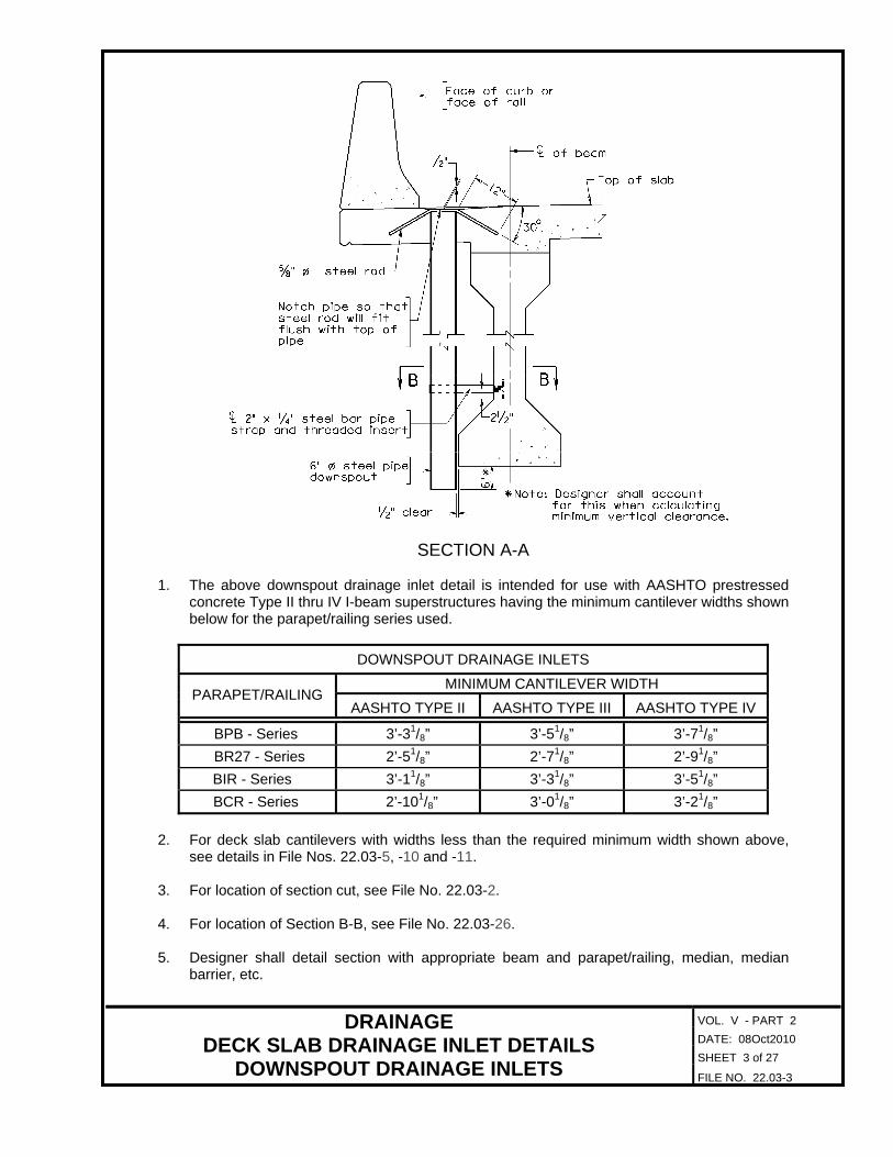
SECTION A-A 1. The above downspout drainage inlet detail is intended for use with AASHTO prestressed
concrete Type II thru IV I-beam superstructures having the minimum cantilever widths shown below for the parapet/railing series used.
DOWNSPOUT DRAINAGE INLETS
MINIMUM CANTILEVER WIDTH PARAPET/RAILING
AASHTO TYPE II AASHTO TYPE III AASHTO TYPE IV
BPB - Series 3’-31/8” 3’-51/8” 3’-71/8”
BR27 - Series 2’-51/8” 2’-71/8” 2’-91/8”
BIR - Series 3’-11/8” 3’-31/8” 3’-51/8”
BCR - Series 2’-101/8” 3’-01/8” 3’-21/8”
2. For deck slab cantilevers with widths less than the required minimum width shown above,
see details in File Nos. 22.03-5, -10 and -11. 3. For location of section cut, see File No. 22.03-2. 4. For location of Section B-B, see File No. 22.03-26. 5. Designer shall detail section with appropriate beam and parapet/railing, median, median
barrier, etc.
VOL. V - PART 2
DATE: 08Oct2010
SHEET 4 of 27
DRAINAGE DECK SLAB DRAINAGE INLET DETAILS
DOWNSPOUT DRAINAGE INLETS FILE NO. 22.03-4
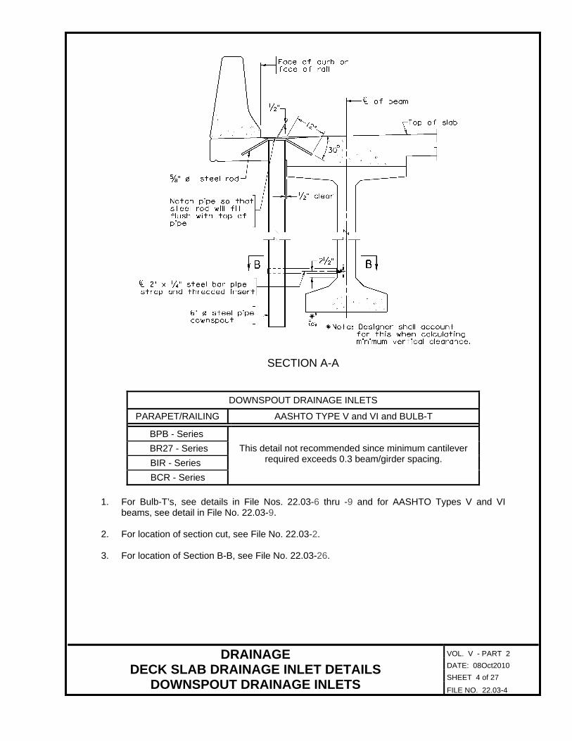
SECTION A-A
DOWNSPOUT DRAINAGE INLETS
PARAPET/RAILING AASHTO TYPE V and VI and BULB-T
BPB - Series
BR27 - Series
BIR - Series
BCR - Series
This detail not recommended since minimum cantilever required exceeds 0.3 beam/girder spacing.
1. For Bulb-T’s, see details in File Nos. 22.03-6 thru -9 and for AASHTO Types V and VI
beams, see detail in File No. 22.03-9. 2. For location of section cut, see File No. 22.03-2. 3. For location of Section B-B, see File No. 22.03-26.
VOL. V - PART 2
DATE: 08Oct2010
SHEET 5 of 27
DRAINAGE DECK SLAB DRAINAGE INLET DETAILS
DOWNSPOUT DRAINAGE INLETS FILE NO. 22.03-5
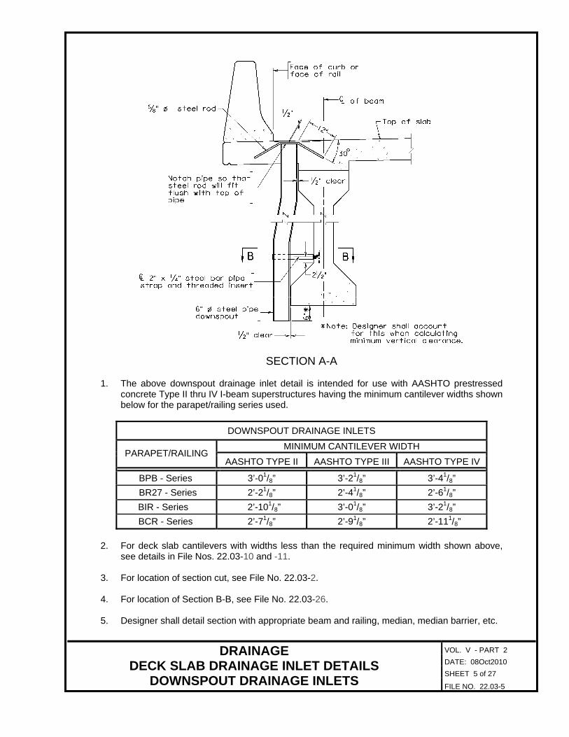
SECTION A-A 1. The above downspout drainage inlet detail is intended for use with AASHTO prestressed
concrete Type II thru IV I-beam superstructures having the minimum cantilever widths shown below for the parapet/railing series used.
DOWNSPOUT DRAINAGE INLETS
MINIMUM CANTILEVER WIDTH PARAPET/RAILING
AASHTO TYPE II AASHTO TYPE III AASHTO TYPE IV
BPB - Series 3’-01/8” 3’-21/8” 3’-41/8”
BR27 - Series 2’-21/8” 2’-41/8” 2’-61/8”
BIR - Series 2’-101/8” 3’-01/8” 3’-21/8”
BCR - Series 2’-71/8” 2’-91/8” 2’-111/8”
2. For deck slab cantilevers with widths less than the required minimum width shown above,
see details in File Nos. 22.03-10 and -11. 3. For location of section cut, see File No. 22.03-2. 4. For location of Section B-B, see File No. 22.03-26. 5. Designer shall detail section with appropriate beam and railing, median, median barrier, etc.

VOL. V - PART 2
DATE: 08Oct2010
SHEET 6 of 27
DRAINAGE DECK SLAB DRAINAGE INLET DETAILS
DOWNSPOUT DRAINAGE INLETS FILE NO. 22.03-6
SECTION A-A 1. The above downspout drainage inlet detail is intended for use with prestressed concrete
Bulb-T superstructures having a cantilever width within the ranges shown below for the parapet/railing series used.
DOWNSPOUT DRAINAGE INLETS FOR BULB-T’S
CANTILEVER WIDTH PARAPET/RAILING
MINIMUM MAXIMUM
BPB - Series 2’-111/2” 3’-41/8”
BR27 - Series 2’-11/2” 2’-61/8”
BIR - Series 2’-91/2” 3’-21/8"
BCR - Series 2’-51/2” 2’-101/8”
2. For deck slab cantilevers having widths less than the required minimum width shown above,
see details in File Nos. 22.03-8 and -9. 3. For location of section cut, see File No. 22.03-2.

VOL. V - PART 2
DATE: 08Oct2010
SHEET 7 of 27
DRAINAGE DECK SLAB DRAINAGE INLET DETAILS
DOWNSPOUT DRAINAGE INLETS FILE NO. 22.03-7
4. For location of Section B-B, see File No. 22.03-26. 5. Designer shall detail section with appropriate beam and railing, median, median barrier, etc. 6. For details of Bulb-T top flange pipe sleeve, see File Nos. 12.03-4 and -5.
VOL. V - PART 2
DATE: 08Oct2010
SHEET 8 of 27
DRAINAGE DECK SLAB DRAINAGE INLET DETAILS
DOWNSPOUT DRAINAGE INLETS FILE NO. 22.03-8
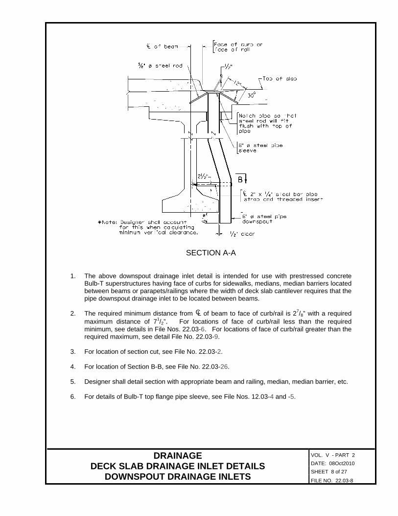
SECTION A-A 1. The above downspout drainage inlet detail is intended for use with prestressed concrete
Bulb-T superstructures having face of curbs for sidewalks, medians, median barriers located between beams or parapets/railings where the width of deck slab cantilever requires that the pipe downspout drainage inlet to be located between beams.
2. The required minimum distance from L of beam to face of curb/rail is 27/8” with a required
maximum distance of 71/2”. For locations of face of curb/rail less than the required minimum, see details in File Nos. 22.03-6. For locations of face of curb/rail greater than the required maximum, see detail File No. 22.03-9.
3. For location of section cut, see File No. 22.03-2. 4. For location of Section B-B, see File No. 22.03-26. 5. Designer shall detail section with appropriate beam and railing, median, median barrier, etc. 6. For details of Bulb-T top flange pipe sleeve, see File Nos. 12.03-4 and -5.
C
VOL. V - PART 2
DATE: 08Oct2010
SHEET 9 of 27
DRAINAGE DECK SLAB DRAINAGE INLET DETAILS
DOWNSPOUT DRAINAGE INLETS FILE NO. 22.03-9
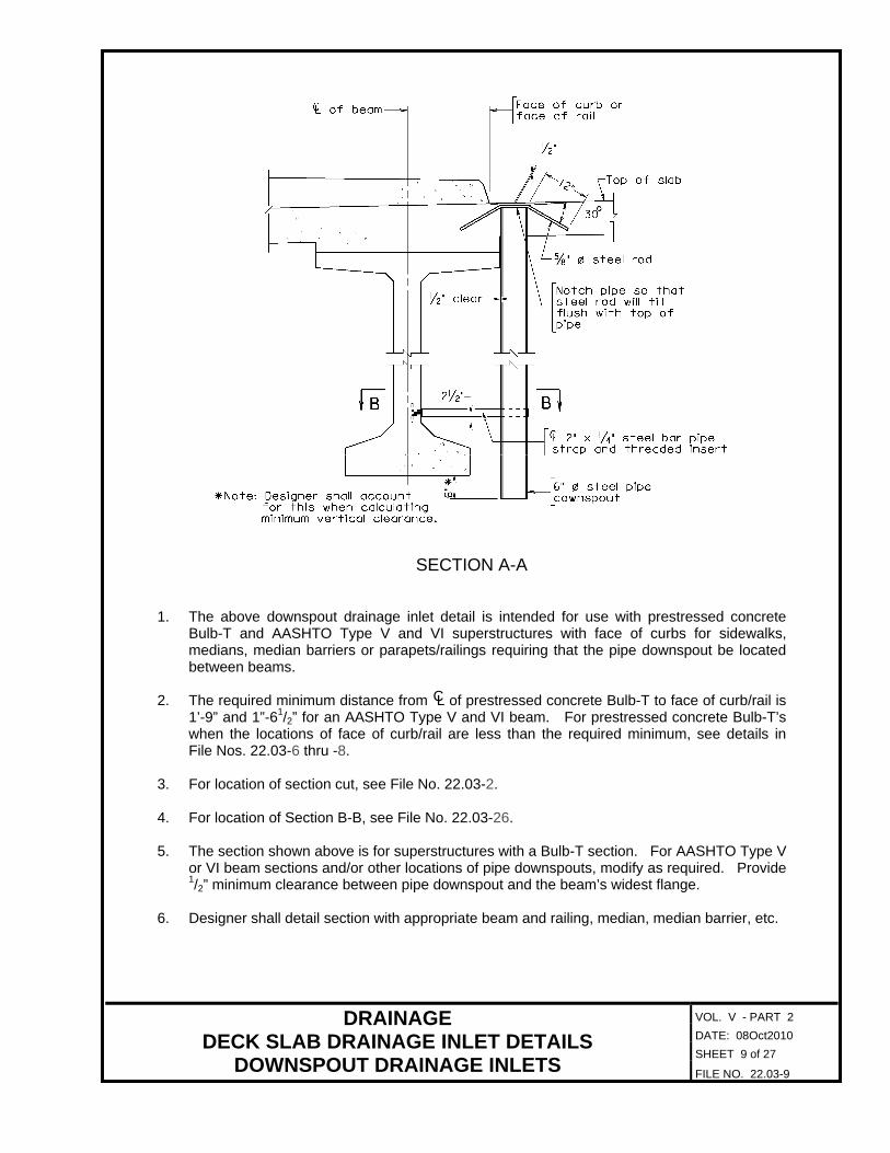
SECTION A-A 1. The above downspout drainage inlet detail is intended for use with prestressed concrete
Bulb-T and AASHTO Type V and VI superstructures with face of curbs for sidewalks, medians, median barriers or parapets/railings requiring that the pipe downspout be located between beams.
2. The required minimum distance from L of prestressed concrete Bulb-T to face of curb/rail is
1’-9” and 1”-61/2” for an AASHTO Type V and VI beam. For prestressed concrete Bulb-T’s when the locations of face of curb/rail are less than the required minimum, see details in File Nos. 22.03-6 thru -8.
3. For location of section cut, see File No. 22.03-2. 4. For location of Section B-B, see File No. 22.03-26. 5. The section shown above is for superstructures with a Bulb-T section. For AASHTO Type V
or VI beam sections and/or other locations of pipe downspouts, modify as required. Provide 1/2” minimum clearance between pipe downspout and the beam’s widest flange.
6. Designer shall detail section with appropriate beam and railing, median, median barrier, etc.
C

VOL. V - PART 2
DATE: 08Oct2010
SHEET 10 of 27
DRAINAGE DECK SLAB DRAINAGE INLET DETAILS
DOWNSPOUT DRAINAGE INLETS FILE NO. 22.03-10
SECTION A-A 1. The above downspout drainage inlet detail is intended for use with AASHTO prestressed
concrete Type II thru IV I-beam superstructures with face of curbs for sidewalks, medians, median barriers located between beams or parapets/railings requires that the pipe downspout be located between beams.
2. The required minimum distance from L of AASHTO prestressed concrete I-beam to face of
curb/rail is as shown below for the beam type used.
DOWNSPOUT DRAINAGE INLETS
AASHTO I-BEAM TYPE
MINIMUM DISTANCE
II 31/2”
III 51/2”
IV 71/2” 3. When the locations of face of curb/rail are less than the required minimum distances shown
above, see details in File Nos. 22.03-3, and -5. 4. For location of section cut, see File No. 22.03-2. 5. For location of Section B-B, see File No. 22.03-26. 6. Designer shall detail section with appropriate beam and railing, median, median barrier, etc.
C

VOL. V - PART 2
DATE: 08Oct2010
SHEET 11 of 27
DRAINAGE DECK SLAB DRAINAGE INLET DETAILS
DOWNSPOUT DRAINAGE INLETS FILE NO. 22.03-11
SECTION A-A 1. The above downspout drainage inlet detail is intended for use with AASHTO prestressed
concrete Type II thru IV I-beam superstructures with face of curbs for sidewalks, medians, median barriers or parapets/railings requiring that the pipe downspout be located between beams.
2. The required minimum distance from L of AASHTO prestressed concrete I-beam to face of
curb/rail is as shown below for the beam type used.
DOWNSPOUT DRAINAGE INLETS
AASHTO I-BEAM TYPE
MINIMUM DISTANCE
II 61/2”
III 81/2”
IV 101/2”
3. When the locations of face of curb/rail are less than the required minimum distances shown
above, see details in File Nos. 22.03-3, -5 and -10. 4. For location of section cut, see File No. 22.03-2. 5. For location of Section B-B, see File No. 22.03-26. 6. Designer shall detail section with appropriate beam and railing, median, median barrier, etc.
C

VOL. V - PART 2
DATE: 08Oct2010
SHEET 12 of 27
DRAINAGE DECK SLAB DRAINAGE INLET DETAILS
DOWNSPOUT DRAINAGE INLETS FILE NO. 22.03-12
SECTION A-A 1. The above downspout drainage inlet detail is intended for use with steel plate girder/rolled
beam superstructures. 2. For location of section cut, see File No. 22.03-2. 3. For location of Section C-C, see File No. 22.03-26. 4. The section shown above is for superstructures with a steel plate girder having a 16” top
flange and a 18” bottom flange. For other plate girder sections, rolled beams and/or other locations of pipe downspouts, modify as required. Provide 1/2” minimum clearance between pipe downspout and the girder/beams widest flange.
5. Designer shall detail section with appropriate beam and railing, median, median barrier, etc. 6. When pipe support straps are attached to weathering steel, a neoprene or vinyl washer shall
be placed between the contact surfaces of the support strap and the hex nut with the weathering steel to isolate the contact between the two surfaces.

VOL. V - PART 2
DATE: 08Oct2010
SHEET 13 of 27
DRAINAGE DECK SLAB DRAINAGE INLET DETAILS
DOWNSPOUT DRAINAGE INLETS FILE NO. 22.03-13
SECTION A-A 1. The above downspout drainage inlet detail is intended for use with steel plate girder/rolled
beam superstructures with face of curbs for sidewalks, medians, median barriers or parapets/railings requiring that the pipe downspout be located between girders/beams.
2. For location of section cut, see File No. 22.03-2. 3. For location of Section C-C, see File No. 22.03-26. 4. The section shown above is for superstructures with a steel plate girder having a 16” top
flange and a 18” bottom flange. For other plate girder sections, rolled beams and/or other locations of pipe downspouts, modify as required. Provide 1/2” minimum clearance between pipe downspout and the girder/beams widest flange.
5. Designer shall detail section with appropriate beam and railing, median, median barrier, etc. 6. When pipe support straps are attached to weathering steel, a neoprene or vinyl washer shall
be placed between the contact surfaces of the support strap and the hex nut with the weathering steel to isolate the contact between the two surfaces.
VOL. V - PART 2
DATE: 08Oct2010
SHEET 14 of 27
DRAINAGE DECK SLAB DRAINAGE INLET DETAILS
GRATE DRAINAGE INLETS FILE NO. 22.03-14
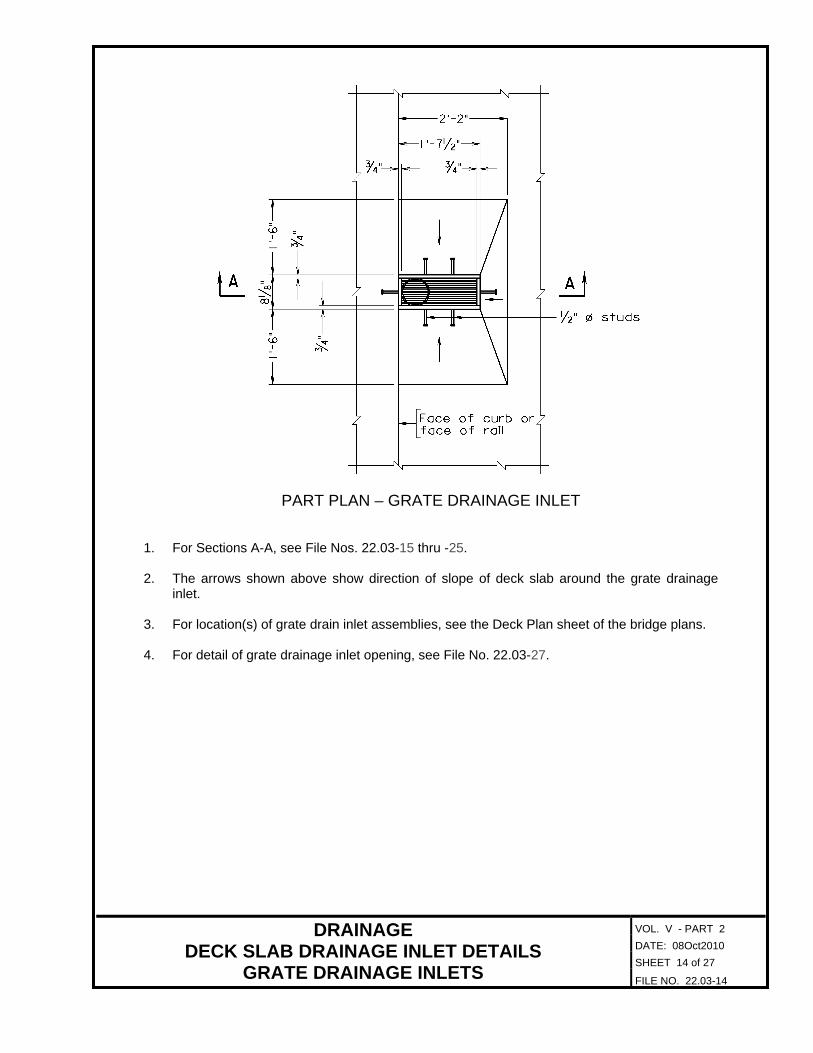
PART PLAN – GRATE DRAINAGE INLET 1. For Sections A-A, see File Nos. 22.03-15 thru -25. 2. The arrows shown above show direction of slope of deck slab around the grate drainage
inlet. 3. For location(s) of grate drain inlet assemblies, see the Deck Plan sheet of the bridge plans. 4. For detail of grate drainage inlet opening, see File No. 22.03-27.

VOL. V - PART 2
DATE: 08Oct2010
SHEET 15 of 27
DRAINAGE DECK SLAB DRAINAGE INLET DETAILS
GRATE DRAINAGE INLETS FILE NO. 22.03-15
SECTION A-A 1. The above grate drainage inlet detail is intended for use with AASHTO prestressed concrete
Type II thru IV I-beam superstructures having the minimum cantilever widths shown below for the parapet/railing series used.
GRATE DRAINAGE INLETS
MINIMUM CANTILEVER WIDTH PARAPET/RAILING
AASHTO TYPE II AASHTO TYPE III AASHTO TYPE IV
BPB - Series 3’-07/8” 3’-27/8” 3’-47/8”
BR27 - Series 2’-27/8” 2’-47/8” 2’-67/8”
BIR - Series 2’-107/8” 3’-07/8” 3’-27/8”
BCR - Series 2’-77/8” 2’-97/8” 2’-117/8”
2. For deck slab cantilevers with widths less than the required minimum width shown above,
see details in File Nos. 22.03-17, -22 and -23. 3. For location of section cut, see File No. 22.03-14. 4. For location of Section B-B, see File No. 22.03-26. 5. Designer shall detail section with appropriate beam and railing, median, median barrier, etc.
VOL. V - PART 2
DATE: 08Oct2010
SHEET 16 of 27
DRAINAGE DECK SLAB DRAINAGE INLET DETAILS
GRATE DRAINAGE INLETS FILE NO. 22.03-16
SECTION A-A
DOWNSPOUT DRAINAGE INLETS
PARAPET/RAILING AASHTO TYPE V and VI and BULB-T
BPB - Series
BR27 - Series
BIR - Series
BCR - Series
This detail not recommended since minimum cantilever required exceeds 0.3 beam/girder spacing.
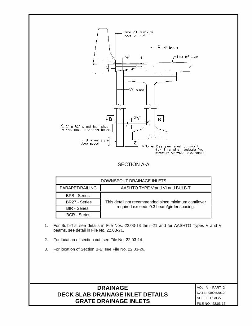
1. For Bulb-T’s, see details in File Nos. 22.03-18 thru -21 and for AASHTO Types V and VI
beams, see detail in File No. 22.03-21. 2. For location of section cut, see File No. 22.03-14. 3. For location of Section B-B, see File No. 22.03-26.
VOL. V - PART 2
DATE: 08Oct2010
SHEET 17 of 27
DRAINAGE DECK SLAB DRAINAGE INLET DETAILS
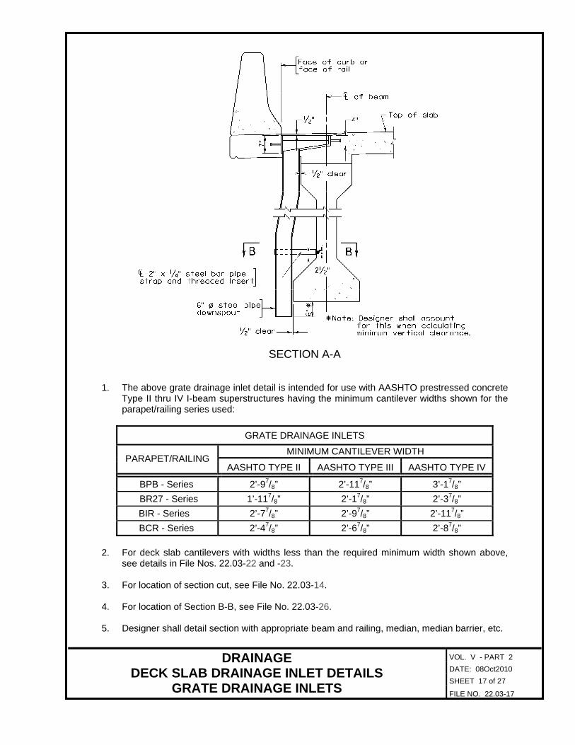
GRATE DRAINAGE INLETS FILE NO. 22.03-17
SECTION A-A 1. The above grate drainage inlet detail is intended for use with AASHTO prestressed concrete
Type II thru IV I-beam superstructures having the minimum cantilever widths shown for the parapet/railing series used:
GRATE DRAINAGE INLETS
MINIMUM CANTILEVER WIDTH PARAPET/RAILING
AASHTO TYPE II AASHTO TYPE III AASHTO TYPE IV
BPB - Series 2’-97/8” 2’-117/8” 3’-17/8”
BR27 - Series 1’-117/8” 2’-17/8” 2’-37/8”
BIR - Series 2’-77/8” 2’-97/8” 2’-117/8”
BCR - Series 2’-47/8” 2’-67/8” 2’-87/8”
2. For deck slab cantilevers with widths less than the required minimum width shown above,
see details in File Nos. 22.03-22 and -23. 3. For location of section cut, see File No. 22.03-14. 4. For location of Section B-B, see File No. 22.03-26. 5. Designer shall detail section with appropriate beam and railing, median, median barrier, etc.

VOL. V - PART 2
DATE: 08Oct2010
SHEET 18 of 27
DRAINAGE DECK SLAB DRAINAGE INLET DETAILS
GRATE DRAINAGE INLETS FILE NO. 22.03-18
SECTION A-A 1. The above grate drainage inlet detail is intended for use with prestressed concrete Bulb-T
superstructures having a cantilever width within the ranges shown below for the parapet/railing series used:
GRATE DRAINAGE INLETS FOR BULB-T’S
CANTILEVER WIDTH PARAPET/RAILING
MINIMUM MAXIMUM
BPB - Series 2’-91/4” 3’-17/8”
BR27 - Series 1’-111/4” 2’-37/8”
BIR - Series 2’-71/4” 2’-117/8”
BCR - Series 2’-31/4” 2’-77/8”
2. For deck slab cantilevers having widths less than the required minimum width shown above,
see details in File Nos. 22.03-20 and -21. 3. For location of section cut, see File No. 22.03-14. 4. For location of Section B-B, see File No. 22.03-26.
VOL. V - PART 2
DATE: 08Oct2010
SHEET 19 of 27
DRAINAGE DECK SLAB DRAINAGE INLET DETAILS
GRATE DRAINAGE INLETS FILE NO. 22.03-19
5. Designer shall detail section with appropriate beam and railing, median, median barrier, etc. 6. For details of Bulb-T top flange pipe sleeve, see File Nos. 12.03-4 and -5.

VOL. V - PART 2
DATE: 08Oct2010
SHEET 20 of 27
DRAINAGE DECK SLAB DRAINAGE INLET DETAILS
GRATE DRAINAGE INLETS FILE NO. 22.03-20
SECTION A-A 1. The above grate drainage inlet detail is intended for use with prestressed concrete Bulb-T
superstructures with face of curbs for sidewalks, medians, median barriers located between beams or parapets/railings requiring that the pipe downspout of the grate drainage inlet to be located between beams.
2. The required minimum distance from L of beam to face of curb/rail is 51/8” with a maximum
distance of 93/4”. For locations of face of curb/rail less than the required minimum, see details in File Nos. 22.03-18. For locations of face of curb/rail greater than the required maximum, see detail File No. 22.03-21.
3. For location of section cut, see File No. 22.03-14. 4. For location of Section B-B, see File No. 22.03-26. 5. Designer shall detail section with appropriate beam and railing, median, median barrier, etc. 6. For details of Bulb-T top flange pipe sleeve, see File Nos. 12.03-4 and -5.
C

VOL. V - PART 2
DATE: 08Oct2010
SHEET 21 of 27
DRAINAGE DECK SLAB DRAINAGE INLET DETAILS
GRATE DRAINAGE INLETS FILE NO. 22.03-21
SECTION A-A 1. The above grate drainage inlet detail is intended for use with prestressed concrete Bulb-T
and AASHTO Type V and VI superstructures with face of curbs for sidewalks, medians, median barriers or parapets/railings requiring that the pipe downspout of the grate drainage inlet be located between beams.
2. The required minimum distance from L of prestressed concrete Bulb-T to face of curb/rail is
1’-111/4” and 1”-83/4” for an AASHTO Type V and VI beam. For prestressed concrete Bulb-T’s when the locations of face of curb/rail are less than the required minimum, see details in File Nos. 22.03-18 thru -20.
3. For location of section cut, see File No. 22.03-14. 4. For location of Section B-B, see File No. 22.03-26. 5. The section shown above is for superstructures with a Bulb-T section. For AASHTO Type V
or VI beam sections and/or other locations of pipe downspouts, modify as required. Provide 1/2” minimum clearance between pipe downspout and the beam’s widest flange.
6. Designer shall detail section with appropriate beam and railing, median, median barrier, etc.
C

VOL. V - PART 2
DATE: 08Oct2010
SHEET 22 of 27
DRAINAGE DECK SLAB DRAINAGE INLET DETAILS
GRATE DRAINAGE INLETS FILE NO. 22.03-22
SECTION A-A 1. The above grate drainage inlet detail is intended for use with AASHTO prestressed concrete
Type II thru IV I-beam superstructures with face of curbs for sidewalks, medians, median barriers or parapets/railings requiring that the pipe downspout of the grate drainage inlet be located between beams.
2. The required minimum distance from L of AASHTO prestressed concrete I-beam to face of
curb/rail is as shown below for the beam type used.
GRATE DRAINAGE INLETS
AASHTO I-BEAM TYPE
MINIMUM DISTANCE
II 53/4” III 73/4” IV 93/4”
3. When the locations of face of curb/rail are less than the required minimum distances shown
above, see details in File Nos. 22.03-15 and -17. 4. For location of section cut, see File No. 22.03-14. 5. For location of Section B-B, see File No. 22.03-26. 6. Designer shall detail section with appropriate beam and railing, median, median barrier, etc.
C
VOL. V - PART 2
DATE: 08Oct2010
SHEET 23 of 27
DRAINAGE DECK SLAB DRAINAGE INLET DETAILS
GRATE DRAINAGE INLETS FILE NO. 22.03-23
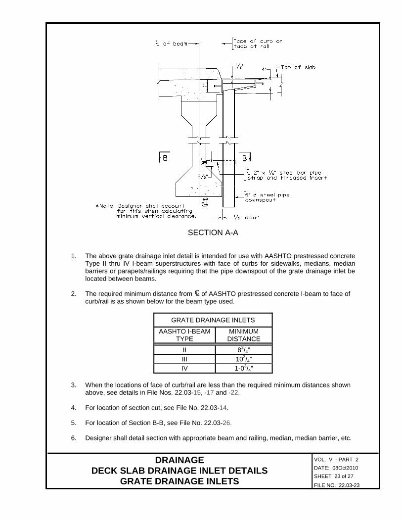
SECTION A-A 1. The above grate drainage inlet detail is intended for use with AASHTO prestressed concrete
Type II thru IV I-beam superstructures with face of curbs for sidewalks, medians, median barriers or parapets/railings requiring that the pipe downspout of the grate drainage inlet be located between beams.
2. The required minimum distance from L of AASHTO prestressed concrete I-beam to face of
curb/rail is as shown below for the beam type used.
GRATE DRAINAGE INLETS
AASHTO I-BEAM TYPE
MINIMUM DISTANCE
II 83/4”
III 103/4”
IV 1-03/4” 3. When the locations of face of curb/rail are less than the required minimum distances shown
above, see details in File Nos. 22.03-15, -17 and -22. 4. For location of section cut, see File No. 22.03-14. 5. For location of Section B-B, see File No. 22.03-26. 6. Designer shall detail section with appropriate beam and railing, median, median barrier, etc.
C

VOL. V - PART 2
DATE: 08Oct2010
SHEET 24 of 27
DRAINAGE DECK SLAB DRAINAGE INLET DETAILS
GRATE DRAINAGE INLETS FILE NO. 22.03-24
SECTION A-A 1. The above grate drainage inlet detail is intended for use with steel plate girder/rolled beam
superstructures. 2. For location of section cut, see File No. 22.03-14. 3. For location of Section C-C, see File No. 22.03-26. 4. The section shown above is for superstructures with a steel plate girder having a 16” top
flange and a 18” bottom flange. For other plate girder sections, rolled beams and/or other locations of pipe downspouts, modify as required. Provide 1/2” minimum clearance between pipe downspout and the girder/beam’s widest flange.
5. Designer shall detail section with appropriate beam and railing, median, median barrier, etc. 6. When pipe support straps are attached to weathering steel, a neoprene or vinyl washer shall
be placed between the contact surfaces of the support strap and the hex nut with the weathering steel to isolate the contact between the two surfaces.

VOL. V - PART 2
DATE: 08Oct2010
SHEET 25 of 27
DRAINAGE DECK SLAB DRAINAGE INLET DETAILS
GRATE DRAINAGE INLETS FILE NO. 22.03-25
SECTION A-A 1. The above grate drainage inlet detail is intended for use with steel plate girder/rolled beam
superstructures with face of curbs for sidewalks, medians, median barriers or parapets/railings requiring that the pipe downspout of the grate drainage inlet be located between girders/beams.
2. For location of section cut, see File No. 22.03-14. 3. For location of Section C-C, see File No. 22.03-26. 4. The section shown above is for superstructures with a steel plate girder having a 16” top
flange and a 18” bottom flange. For other plate girder sections, rolled beams and/or other locations of pipe downspouts, modify as required. Provide 1/2” minimum clearance between pipe downspout and the girder/beam’s widest flange.
5. Designer shall detail section with appropriate beam and railing, median, median barrier, etc. 6. When pipe support straps are attached to weathering steel, a neoprene or vinyl washer shall
be placed between the contact surfaces of the support strap and the hex nut with the weathering steel to isolate the contact between the two surfaces.

VOL. V - PART 2
DATE: 08Oct2010
SHEET 26 of 27
DRAINAGE DECK SLAB DRAINAGE INLET DETAILS
DOWNSPOUT PIPE ATTACHMENT DETAILS FILE NO. 22.03-26
DOWNSPOUT PIPE ATTACHMENT DETAILS:
SECTION B-B – PRESTRESSED CONCRETE BEAMS
SECTION C-C – STEEL BEAMS/GIRDERS 1. H.S. bolts installed in threaded inserts shall be tightened to a snug tight condition as defined
in Section 407 of the VDOT Road and Bridge Specifications. Rotational capacity test will not be required.
2. When pipe support straps are attached to weathering steel, a neoprene or vinyl washer shall
be placed between the contact surfaces of the support strap and the hex nut with the weathering steel to isolate the contact between the two surfaces.

VOL. V - PART 2
DATE: 08Oct2010
SHEET 27 of 27
DRAINAGE DECK SLAB DRAINAGE INLET DETAILS
DRAINAGE INLET OPENING DETAILS FILE NO. 22.03-27
DRAINAGE INLET OPENING DETAILS:
GRATE DRAINAGE INLET OPENING DETAIL
DOWNSPOUT DRAINAGE INLET OPENING DETAIL

VOL. V - PART 2
DATE: 08Oct2010
SHEET 1 of 12
DRAINAGE STORMWATER COLLECTION AND DISCHARGE SYSTEMS
GENERAL INFORMATION FILE NO. 22.04-1
GENERAL INFORMATION: Stormwater runoff intercepted by drainage inlets shall be discharged from the deck slab by either falling directly to surfaces beneath the bridge (discharge to air), or is collected and conveyed to another location on or off the bridge. Collected stormwater runoff is conveyed either to a vertical surface on the bridge by means of a collector pipe suspended beneath the bridge superstructure to downspouts attached to piers or other vertical surfaces of the bridge or to a specified location away from the bridge. Stormwater shall not be discharged openly over any traveled way (either vehicular or pedestrian), unprotected embankments or other ground surfaces where it might cause erosion or undermine structural integrity of the bridge. In such cases, riprap or other means such as energy dissipators, paved slab or splash blocks shall be provided. For bridges over railroads, all stormwater runoff intercepted by deck slab drainage inlets shall be collected and conveyed by longitudinal storm drain collector pipe(s) to a specified location off the railroad property. Discharge to Air: Stormwater runoff intercepted by deck slab drainage inlets shall normally be allowed to fall freely from drainage inlets to surfaces beneath the bridge unless structural and/or environmental constraints preclude doing so. When short vertical downspouts are used to discharge water into the air, they shall be 6 inch minimum diameter steel pipe and shall extend 6” below the bottom of adjacent beam/girder flange. Short vertical downspout pipes shall be located a minimum of 5’-0” away from piers to avoid wind driven spray on bridge components. Stormwater Collection Systems: When project constraints/requirements preclude the discharging of stormwater intercepted by drainage inlets from being discharged into the air, collected stormwater runoff shall normally be conveyed by collector pipes to downspouts attached to piers or other vertical surfaces on the bridge. When project requirements preclude the discharging of stormwater runoff directly into a waterway or other areas such as in environmentally sensitive locations, it shall be necessary to provide a longitudinal storm drain collector pipe to carry the stormwater runoff to a specified location away from the bridge. Collector and downspout pipes shall be 6 inch minimum diameter pipe. Pipes shall be sloped at least 2% (1/4” per foot) or more where conditions allow to provide sufficient velocities at low flow to move silt and small debris to avoid clogging. If collector pipes are exposed, they shall run parallel to the existing lines of the structure and painted to match the general color of the bridge.

VOL. V - PART 2
DATE: 01Jul2011
SHEET 2 of 12
DRAINAGE STORMWATER COLLECTION AND DISCHARGE SYSTEMS
GENERAL INFORMATION FILE NO. 22.04-2
Collector/downspout pipes shall not be concealed (embedded) within pier caps, columns, abutment walls or installed through steel box girders. Cleanouts both upward and downward shall be provided at all key points within the system to facilitate removal of debris and other obstructions. They shall be located so that they are accessible and easily reached by maintenance crews. Costs for furnishing and installing all components of the stormwater collection and discharge system shall be included as a lump sum bid item as shown on the plans. Materials: Steel collector and downspout pipes shall be ASTM A53 Schedule 40 black seamless steel pipe. Steel plates, bars and rods shall be ASTM A36. All bolts shall be ASTM A325. All threaded inserts shall be flared thin slab ferrule 1/2”- 9 NC threaded insert. See File No. 12.09-3. Corrosion Protection: Collector and downspout assemblies and attachments to include all steel plates, pipe, bars, bolts and nuts shall be hot dipped galvanized after fabrication. When pipe support straps are attached to weathering steel, a neoprene or vinyl washer shall be placed between the contact surfaces of the support strap and the hex nut with the weathering steel to isolate the contact between the two surfaces.

VOL. V - PART 2
DATE: 08Oct2010
SHEET 3 of 12
DRAINAGE STORMWATER COLLECTION AND DISCHARGE SYSTEMS
DRAINAGE COLLECTOR PIPE DETAILS FILE NO. 22.04-3
DRAINAGE COLLECTOR PIPE DETAILS:
DRAINAGE COLLECTOR PIPE DETAIL 1. The details shown above and in File Nos. 22.04-4 thru -7 are for the designer’s information
only. See Introduction File No. 22.00-1. 2. For Sections A-A, see File No. 22.04-4. For Sections B-B, see File Nos. 22.04 -5 thru -7. 3. For details of pipe support straps, see File Nos. 22.04-9 and -10. 4. For collector downspout pipe reducer details, see File No. 22.04-8. 5. For pipe hanger details, see File No. 22.04-11.
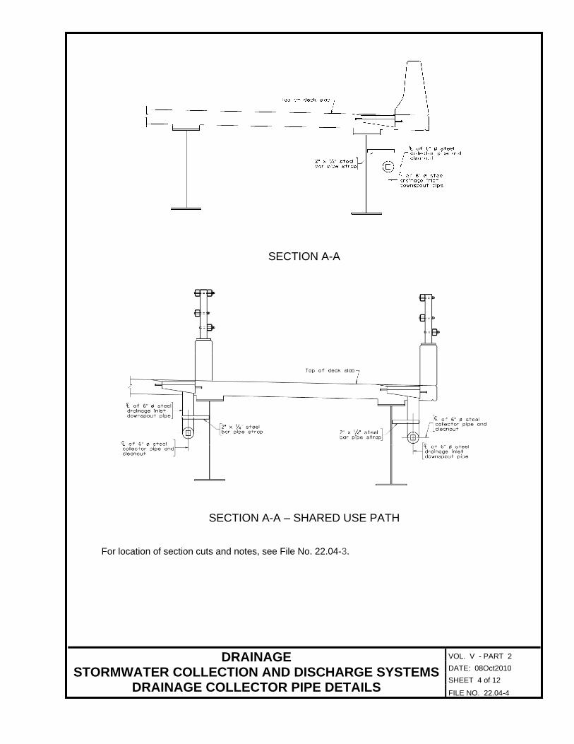
VOL. V - PART 2
DATE: 08Oct2010
SHEET 4 of 12
DRAINAGE STORMWATER COLLECTION AND DISCHARGE SYSTEMS
DRAINAGE COLLECTOR PIPE DETAILS FILE NO. 22.04-4
SECTION A-A
SECTION A-A – SHARED USE PATH For location of section cuts and notes, see File No. 22.04-3.
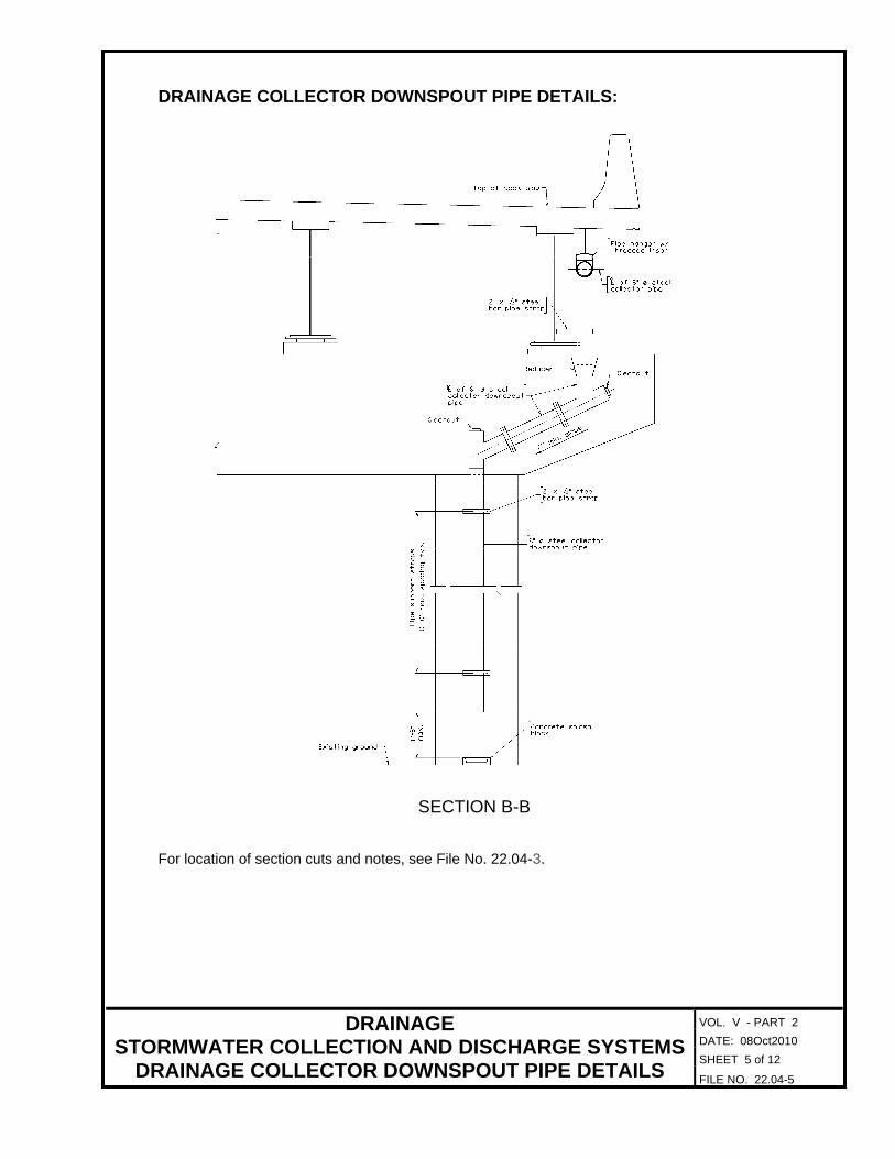
VOL. V - PART 2
DATE: 08Oct2010
SHEET 5 of 12
DRAINAGE STORMWATER COLLECTION AND DISCHARGE SYSTEMS
DRAINAGE COLLECTOR DOWNSPOUT PIPE DETAILS FILE NO. 22.04-5
DRAINAGE COLLECTOR DOWNSPOUT PIPE DETAILS:
SECTION B-B For location of section cuts and notes, see File No. 22.04-3.

VOL. V - PART 2
DATE: 08Oct2010
SHEET 6 of 12
DRAINAGE STORMWATER COLLECTION AND DISCHARGE SYSTEMS
DRAINAGE COLLECTOR DOWNSPOUT PIPE DETAILS FILE NO. 22.04-6
SECTION B-B - SIDEWALK For location of section cuts and notes, see File No. 22.04-3.

VOL. V - PART 2
DATE: 08Oct2010
SHEET 7 of 12
DRAINAGE STORMWATER COLLECTION AND DISCHARGE SYSTEMS
DRAINAGE COLLECTOR DOWNSPOUT PIPE DETAILS FILE NO. 22.04-7
SECTION B-B – SHARED USE PATH For location of section cuts and notes, see File No. 22.04-3.
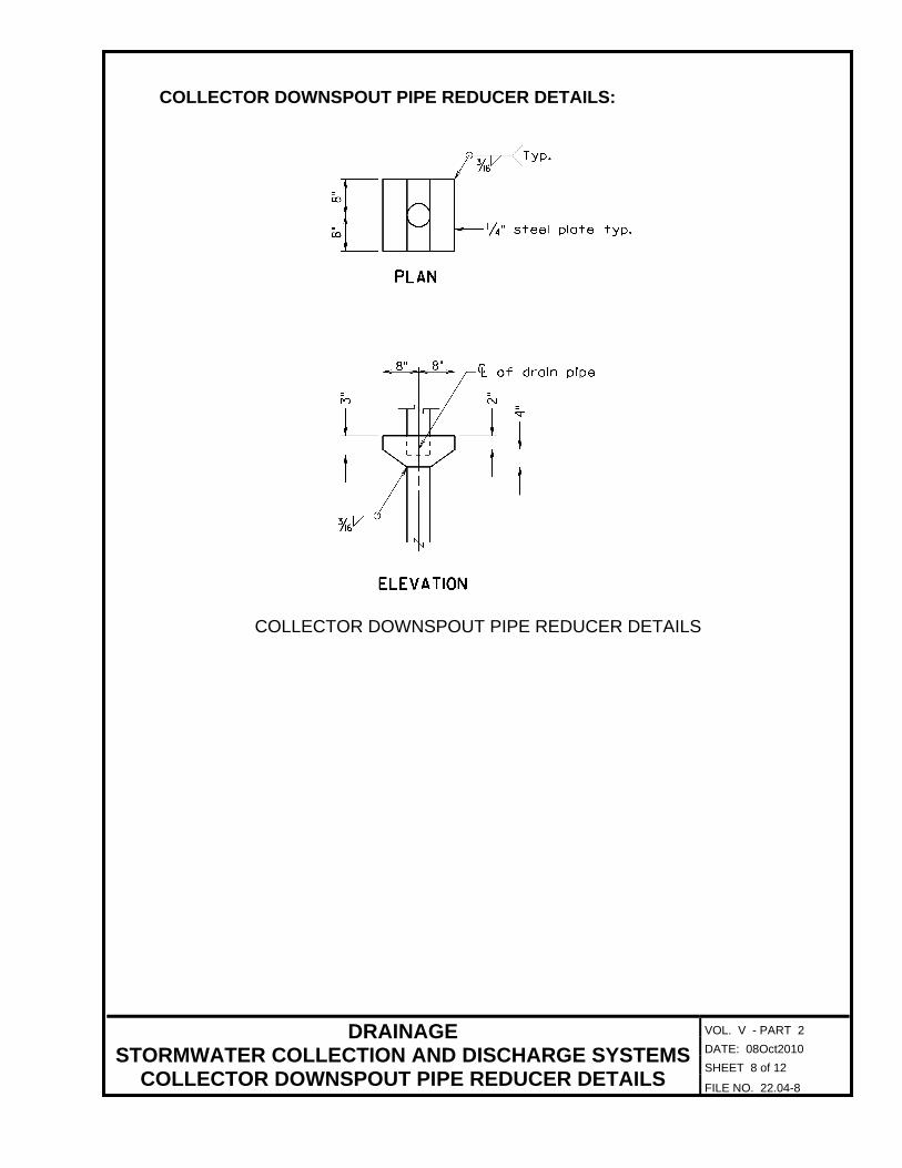
VOL. V - PART 2
DATE: 08Oct2010
SHEET 8 of 12
DRAINAGE STORMWATER COLLECTION AND DISCHARGE SYSTEMS
COLLECTOR DOWNSPOUT PIPE REDUCER DETAILS FILE NO. 22.04-8
COLLECTOR DOWNSPOUT PIPE REDUCER DETAILS:
COLLECTOR DOWNSPOUT PIPE REDUCER DETAILS

VOL. V - PART 2
DATE: 08Oct2010
SHEET 9 of 12
DRAINAGE STORMWATER COLLECTION AND DISCHARGE SYSTEMS
PIPE SUPPORT STRAP DETAILS FILE NO. 22.04-9
PIPE SUPPORT STRAP DETAILS:
PIPE SUPPORT STRAP DETAIL 1. The pipe support strap detail shown above is intended to be used for attachment of collector
and downspout pipe to flat faces of beams/girders, abutment walls, pier caps and pier columns.
2. Provide dimension on plan detail.

VOL. V - PART 2
DATE: 08Oct2010
SHEET 10 of 12
DRAINAGE STORMWATER COLLECTION AND DISCHARGE SYSTEMS
PIPE SUPPORT STRAP DETAILS FILE NO. 22.04-10
PIPE SUPPORT STRAP DETAIL – CIRCULAR FACE 1. The pipe support strap detail shown above is intended to be used for attachment of collector
and downspout pipe to faces of circular pier columns. 2. Provide dimension on plan detail. 3. Provide circular pier column radius on plan detail.

VOL. V - PART 2
DATE: 08Oct2010
SHEET 11 of 12
DRAINAGE STORMWATER COLLECTION AND DISCHARGE SYSTEMS
PIPE HANGER DETAILS FILE NO. 22.04-11
PIPE HANGER DETAILS:
PIPE HANGER DETAIL
ALTERNATE PIPE HANGER DETAIL

VOL. V - PART 2
DATE: 08Oct2010
SHEET 12 of 12
DRAINAGE STORMWATER COLLECTION AND DISCHARGE SYSTEMS
PIPE HANGER DETAILS FILE NO. 22.04-12
ALTERNATE PIPE HANGER ROD DETAIL

VOL. V - PART 2
DATE: 08Oct2010
SHEET 1 of 4
DRAINAGE DECK SLAB DRAINAGE DETAILS PLAN SHEET
GENERAL INFORMATION FILE NO. 22.05-1
GENERAL INFORMATION: This section of the chapter shows typical drainage details that may be used in a plan assembly. Included is a check list for completing this sheet. It is not the intent of the sample deck slab drainage detail sheet and check list to show the practices and requirements for the design and layout of the deck slab drainage system. The sample deck slab drainage detail sheet shown is intended only to provide the designer with the type of details that may be used for a complete deck slab drainage detail sheet. There may be details shown that may not be necessary for some bridge drainage systems. Information placed in blocks is for designer’s information only and is not to be placed on the deck slab drainage detail sheet. The practices for the completion of interior sheets contained in Chapter 4 shall be adhered to.

DateDesigned: ...........
Drawn: ................
Checked: ............2010, Commonwealth of Virginiac
No. Description Date
STRUCTURE AND BRIDGE DIVISION
COMMONWEALTH OF VIRGINIA
DEPARTMENT OF TRANSPORTATION
Revisions
ROUTE
FEDERAL AID
PROJECT ROUTE PROJECT
STATE SHEET
NO.
VA.
STATEROUTE
FEDERAL AID
PROJECT ROUTE PROJECT
STATE SHEET
NO.
VA.
STATE
STRUCTURAL ENGINEER
RICHMOND, VA
VDOT S&B DIVISION
Plan
FILE NO. 22.05-2
SHEET 2 of 4
DATE: 08Oct2010
VOL. V - PART 2
DECK PLAN
Aug. 2010 999-
SBJ
LML
WJW
29 0029-076-113, B604 15
SECTION A-A
SECTION B-B
Face of backwall
L of jointC
SL0401
SL0401
series bars
SB05 and SC05
series bars
SB05 and SC05
ES0401
ES0402
EB0501
EB0501
1’-7"
1’-9"
ET0502 ROBL
ET0501 LOBL
ET0502 ROBL
ET0501 LOBL
Face of backwall
ET0503*
L of jointC
*but are actually located in each overhang.
ET0503 bars are shown in this section for clarity,
2�"
2�"
ET0503*
SL0603 SL0602SL0602
SL0604 SL0604SL0603
39’-0" 40’-0"
176’-0"
176’-0" 169’-0"
Face of curb
Face of curb
Face of curb
Face of median curb
Face of median curb
Face of curb
Face of curb
Face of curb
Abutment A
Face of backwall
Abutment B
Face of backwall
L Pier 1
L Pier 2
130’-0"
SL0401 top & bottom
1’-3" min. lap
SL0401 top & bottom
1’-3" min. lap
L 2" longitudinal joint
University Blvd. LC
B
C
6" SB0501 LOBL and SB0502 ROBL - 472 spa. @ 12" = 472’-0"
6"
C
C
MT0301 LOBL and MT0302 ROBL - 473 spa. @ 12" = 473’-0"
MT0301 LOBL and MT0302 ROBL - 473 spa. @ 12" = 473’-0"
2 - ET0501
typ. at overhangs
ET0503 top and bottom
2 - ET0502
ty
p.
bet
wee
n gir
ders
10 -
ES0402
@ 12"
max.
spa.
typ. between girders
EB0501
2 - ET0501
typ. at overhangs
ET0503 top and bottom
ty
p.
bet
wee
n gir
ders
10 -
ES0401
@ 12"
max.
spa.
2 - ET0502
typ. between girders
EB0501
AA
BB
SL0603
& 2 -
SL0604
SL0603
& 2 -
SL0604
2 -
SL0602
&
SL0603
2 -
SL0602
&
SL0603
8"
8"
8"
8"
SC0501 LOBL and SC0502 ROBL top & bottom - 473 spa. @ 12" = 473’-0"
SC0403 top - 473 spa. @ 12" = 473’-0"
*
*
*
*
(42 total
spaces).
SL0401 bars
Space bet
wee
n to
p
bars (5
4 total
spaces).
Space bet
wee
n to
p
SL0401
median curb
Face of
median curb
Face of
(42 total
spaces).
SL0401 bars
Space bet
wee
n to
p
bars (5
4 total
spaces).
Space bet
wee
n to
p
SL0401
(match line)
Midspan
(match line)
Midspan
12"
12"
12"
12"
C
C
C
typ. for SL06 series
2’-6" min. lap
typ. for SL06 series
2’-6" min. lap
sheet 8.
For further details, see
typ. at median overhangs.
every top SC series bar
SC0403 top lap with
L junction box14’-6"
L junction box
L junction box
61’-6" 4’-6"
2’-11"
25’-0" 95’-0" 25’-0"14’-0"
inlet #1
L of drainage
inlet #1
L of drainageC
C
inlet #2
L of drainage C
inlet #2
L of drainageC
inlet #1
L of drainageC
36’-0"14’-0"14’-0"25’-0"
inlet #1
L of drainageC
inlet #1
L of drainageC
inlet #2
L of drainageC
inlet #1
L of drainageC
2’-11"
L of Rte 29
1
Not to scale
LOCL denotes left of centerline and ROCL denotes right of centerline.
For details of junction box, see sheet 23.
For elastomeric expansion dam details, see sheet 18.
For drainage assembly details, see sheet 17.
For additional reinforcement details, see sheets 8, 19, 21, and 22.
Notes:
b99999015.d
gn
DECK SLAB PLAN
2
2
2
2
2
SAMPLE DRAINAGE ASSEMBLY DETAILS SHEET
DECK SLAB DRAINAGE DETAILS PLAN SHEET
DRAINAGE

PLAN
ELEVATION
�
�Typ.
10’-
0"
max.
1’-
8"
max.
8"
8" 8"
Not to scale
Girder web
C
L pier
6"
Top of slab
2�
"
ty
p.
Pier 1, see Drainage Assembly Layout.
Shown for Pier 2 looking upstation. For
PIER SIDE ELEVATION
8"
2’-2"
�"
1’-
6"
1’-
6"
�"
�"
�"
anchor typ.
�" o stud/
AA
7"
DateDesigned: ...........
Drawn: ................
Checked: ............2010, Commonwealth of Virginiac
No. Description Date
STRUCTURE AND BRIDGE DIVISION
COMMONWEALTH OF VIRGINIA
DEPARTMENT OF TRANSPORTATION
Revisions
ROUTE
FEDERAL AID
PROJECT ROUTE PROJECT
STATE SHEET
NO.
VA.
STATEROUTE
FEDERAL AID
PROJECT ROUTE PROJECT
STATE SHEET
NO.
VA.
STATE
STRUCTURAL ENGINEER
RICHMOND, VA
VDOT S&B DIVISION
29 0029-076-113, B604
SBJ
LML
WJW
Cleanout typ.
Top of slab
Girder web
Reducer
Top of slab
4"
�"
girderLC
3"
4"
2"
PL � typ.
curb
Face of
1’-7�"
Pier cap
Existing ground
Plan
999-
VOL. V - PART 2
SHEET 3 of 4
FILE NO. 22.05-3
10
9 11
13
12
4
7
17
4
Cleanout typ.
Reducer typ.
typ.
Reducer
typ.
Cleanout
typ.
Cleanout
PIER PLAN - COLLECTOR/DOWNSPOUT PIPE DETAIL
collector pipe
L of drainCC
collector pipe
L of drain
Drainage inlet #1
Drainage inlet #2
6
To drains # 1 and #2
To drains #1 and #2
To drains #1 and #2
To drains #1 and #2
1’-1�"
DRAINAGE
/
pier attachment
Downspout to
PIER ELEVATION - DRAINAGE COLLECTOR DOWNSPOUT PIPE DETAIL
3
5
w/nut
�" o bolt
/C
bolts w/nuts
L of �" o
/
/
/
downspout pipe
6" o steel collector
downspout pipe
collector
6" o steel
block typ.
Concrete splash
downspout pipe
6" o steel collector/
C
pipe
downspout
6" o steel/
downspout pipe
L of 6" o steel collectorC /
Pier cap
DOWNSPOUT REDUCER DETAILS
bar pipe strap
2" x �" steel
bar pipe strap
2" x �" steel
pipe typ.
Collector downspout
typ.
Collector pipe
Aug 2010
L drain pipeC
TYPICAL PIPE SUPPORT STRAP DETAILS
SECTION A-A
TYPICAL GRATE DRAINAGE INLET DETAILS
PART PLAN
shared use path at Abutment A
Shown for grate drainage inlets in
below bottom flange
Extend 6" minimum
shared use path at piers
Shown for drainage inlets in
bottom flange of girder
downspout 6" below
Abutment A extend
For drainage inlets at
strap
Pipe support
strap
Pipe support
strap typ.
Pipe support
Drainage inlet #1
strap
Pipe support
2�"
typ.
BEAM PIER CAP/COLUMN
pipe
L of downspout
/C
typ.
w/lock washers
adhesive anchor
L of �" o
pipe
collector/downspout
L of 6" o steelC /
wall
or abutment
cap/column
Face of pier
bar pipe strap
2" x �" steel
hex nut
�" o bolt w//
11" at pier columns
8" at pier caps
b99999017.d
gn
Estimated Quantities Sheet.
shown shall be included as a lump sum bid item as shown on the
Costs for furnishing and installing the deck slab drainage system
the Engineer to clear the grate drainage inlet assembly.
Reinforcing steel in deck slab may be shifted or cut as directed by
after fabrication.
plates, bars studs, bolts and nuts shall be hot dipped galvanized
Welded frame, grate and downspout pipe assembly to include all steel
ASTM A36. All bolts shall be ASTM A325.
40 black seamless steel pipe. Steel plates, bars and rods shall be
Steel pipe for collector/downspout piping shall be ASTM A53 Schedule
For location of drainage inlets, see sheet 15.
Notes
8
8
8
DRAINAGE COLLECTOR PIPE DETAIL
Shown with BR27C rail
Reducer
2% min. slope
8�
"
C
8�
"
6 spa. @ �" = 5�"
2" x �" steel bars.
1�"
1�"
DRAINAGE INLET GRATE DETAIL
steel bars
L of 2" x �"
14
bar
2" x �" steel
10’ max. spacing
strap typ.
Pipe support
pipe
6" o steel collector
downspout pipe
6" o steel collector /
DECK SLAB DRAINAGE DETAILS PLAN SHEET DRAINAGE ASSEMBLY DETAILS
SAMPLE DRAINAGE ASSEMBLY DETAILS PLAN SHEETDATE: 08Oct2010

VOL. V - PART 2
DATE: 08Oct2010
SHEET 4 of 4
DRAINAGE DECK SLAB DRAINAGE DETAILS PLAN SHEET
CHECK LIST FILE NO. 22.05-4
CHECK LIST FOR SAMPLE DECK SLAB DRAINAGE DETAIL SHEET:
The location of drainage inlets is typically shown on the DECK SLAB PLAN of the DECK PLAN sheet. Show and label L of drainage inlet(s) along face of curb/rail. Dimension locations from L of piers. Show TYPICAL DOWNSPOUT/GRATE DRAINAGE INLET DETAILS as required. Include the appropriate SECTION A-A details. Show DRAINAGE COLLECTOR PIPE DETAIL showing the drainage collector pipes conveying the stormwater runoff from the drainage inlets to the piers or other vertical surfaces of the bridge. Minimum slope of longitudinal collector pipe shall be 2%. Maximum spacing of steel attachment bars shall be 10’-0” on centers. Detail not required when stormwater is discharged directly into the air from the drainage inlet downspout. Show PIER PLAN - COLLECTOR/DOWNSPOUT PIPE DETAIL showing the collector downspout configuration for conveying the stormwater from the drainage collector pipes to the pier cap and down the pier column(s). Detail not required when stormwater is discharged directly into the air from the drainage inlet downspout. Show PIER ELEVATION - DRAINAGE COLLECTOR DOWNSPOUT PIPE DETAIL showing the routing of downspout pipes to the pier columns. Show all cleanouts, reducers and support brackets. Maximum spacing of support brackets shall be 10’-0” on centers. Detail not required when stormwater is discharged directly into the air from the drainage inlet downspout. Show DOWNSPOUT REDUCER DETAILS. Show TYPICAL PIPE SUPPORT STRAP DETAILS. Provide dimension(s) from face of beam/girder web and pier cap/column to L of downspout pipe. Provide minimum 1/2" clearance between pipe downspout and beam/girder flanges and webs. Show Notes as required. Add appropriate sheet number(s). For instructions on completing the notes, see File No. 04.03. For instructions on completing the title block, see File No. 04.04-2. For instructions on completing the project block, see File No. 04.01. For instructions on completing this portion of the sheet, see File No. 04.04-3. For instructions on completing the block for sealing, signing and dating this sheet, see File Nos. 01.16-1 thru -7. Show appropriate drainage inlet opening detail.
1
3
4
5
6
7
8
9
10
11
12
13
C
CC
2
14

DRAINAGE ABUTMENT DRAINAGE
GENERAL INFORMATION
VOL. V - PART 2
DATE: 09Jul2012
SHEET 1 of 1
FILE NO. 22.06-1
GENERAL INFORMATION: For practices and requirements regarding the detailing of abutment drainage systems, refer to the appropriate section(s) of Chapter 17: Abutments.

DRAINAGE INTEGRAL / JOINTLESS BRIDGE DRAINAGE
GENERAL INFORMATIONS
VOL. V - PART 2
DATE: 09Jul2012
SHEET 1 of 1
FILE NO. 22.07-1
GENERAL INFORMATION: For practices and requirements regarding the detailing of full integral, semi-full integral and deck slab extension drainage systems, refer to the appropriate section(s) of Chapter 17: Abutments.