Embed Size (px)
Citation preview
FP7 CONCERTO Deliverable D6.4
11
Figure 5: TVONE TASK 1T-C2-150
The videos are then received on the coaxial entrance of the VITEC Optibase MGW PICO (Figure 6) which operates the analogue to digital conversion and provides the digital videos to the Proxy Server through an Ethernet cable.
Figure 6: VITEC Optibase MGW PICO
Finally a PC laptop, called ‘Proxy server’, is deployed in the ambulance and it is in charge to centralize all the different flows acquired in the emergency area, to provide quality control and adaptation through the application controller and to add adequate protection before transmission (FEC). The Proxy Server acts taking into account cross-layer signalling information on QoS and priority requirements received through the DDE. Moreover, a module will transform the multiple AVC streams into a unique MVC stream, and another module will cypher the different streams for the security aspect.
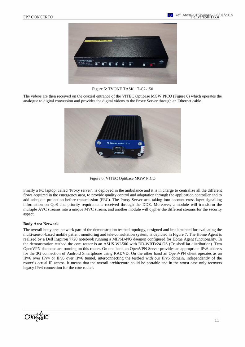
Body Area Network The overall body area network part of the demonstration testbed topology, designed and implemented for evaluating the multi-sensor-based mobile patient monitoring and tele-consultation system, is depicted in Figure 7. The Home Agent is realized by a Dell Inspiron 7720 notebook running a MIP6D-NG daemon configured for Home Agent functionality. In the demonstration testbed the core router is an ASUS WL500 with DD-WRTv24 OS (CrushedHat distribution). Two OpenVPN daemons are running on this router. On one hand an OpenVPN Server provides an appropriate IPv6 address for the 3G connection of Android Smartphone using RADVD. On the other hand an OpenVPN client operates as an IPv6 over IPv4 or IPv6 over IPv6 tunnel, interconnecting the testbed with our IPv6 domain, independently of the router’s actual IP access. It means that the overall architecture could be portable and in the worst case only recovers legacy IPv4 connection for the core router.
Ref. Ares(2015)54043 - 08/01/2015
FP7 CONCERTO Deliverable D6.4
12
Figure 7: Body area network demonstration setup
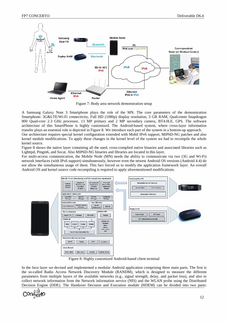
A Samsung Galaxy Note 3 Smartphone plays the role of the MN. The core parameters of the demonstration Smartphone: 3G<E/Wi-Fi connectivity, Full HD (1080p) display resolution, 3 GB RAM, Qualcomm Snapdragon 800 Quad-core 2.3 GHz processor, 13 MP primary and 2 MP secondary camera, BT4.0LE, GPS. The software architecture of this SmartPhone is highly customized. The Android-based system, where cross-layer information transfer plays an essential role is depicted in Figure 8. We introduce each part of the system in a bottom-up approach. Our architecture requires special kernel configuration extended with Mobil IPv6 support, MIP6D-NG patches and also kernel module modifications. To apply these changes in the kernel level of the system we had to recompile the whole kernel source. Figure 8 shows the native layer containing all the used, cross-complied native binaries and associated libraries such as Lighttpd, Pingm6, and Socat. Also MIP6D-NG binaries and libraries are located in this layer. For multi-access communication, the Mobile Node (MN) needs the ability to communicate via two (3G and Wi-Fi) network interfaces (with IPv6 support) simultaneously, however even the newest Android OS versions (Android 4.4) do not allow the simultaneous usage of them. This fact forced us to modify the application framework layer. An overall Android OS and kernel source code recompiling is required to apply aforementioned modifications.
Figure 8: Highly customized Android-based client terminal
In the Java layer we devised and implemented a modular Android application comprising three main parts. The first is the so-called Radio Access Network Discovery Module (RANDM), which is designed to measure the different parameters from multiple layers of the available networks (e.g., signal strength, delay, and packet loss), and also to collect network information from the Network information service (NIS) and the WLAN probe using the Distributed Decision Engine (DDE). The Handover Decision and Execution module (HDEM) can be divided into two parts:

FP7 CONCERTO Deliverable D6.4
13
Handover Decision (HDM) and Handover Execution Module (HEM). HEM communicates with the native MIP6D-NG daemon, creates and sends flow register and flow update messages (see later) induced by the advanced decision algorithm. The register message allocates and initializes a new flow entry to the selected network interface while the update message updates an existing flow by the Flow Identifier (FID). For the cross-layer information exchange a socket-based communication scheme was designed and developed. HDM decides about the necessity of the handoff based on the decision algorithm (see later in more detail). HDM directs the HEM to send flow register or update command to MIP6D-NG. The HDM is a modular, exchangeable part of the architecture, thus we can modify the offloading decision scheme easily. Medical data are provided by two different wearable devices: a Zephyr HxM and a Samsung Gear Fit Smartwatch. The Gear Fit (Figure 9) communicates via Bluetooth 4.0 LE with host Android Smartphone. It has a 1.84” Curved sAMOLED touchscreen display and possesses different built-in sensors, such as accelerometer, gyroscope pedometer and heart rate monitor.
Figure 9: Samsung Gear Fit wearable sensor device
The Zephyr HxM (Figure 10), which also prefers Bluetooth communication, is able to measure heart rate, speed and distance. Bluetooth low energy or Bluetooth LE (or BT Smart) is intended to provide reduced power consumption. BT LE is used in the healthcare, fitness, security and home entertainment applications. It uses 2.4 GHz frequencies, and the maximum of data rate is 1 Mbit/s.
Figure 10: Zephyr HxM wearable heart rate sensor
2.1.1.2 Hospital
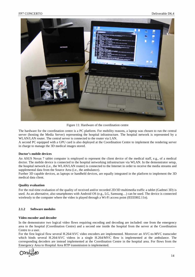
Coordination Centre The hardware for the demonstration setup of the Coordination Centre is shown in Figure 11.
FP7 CONCERTO Deliverable D6.4
14
Figure 11: Hardware of the coordination centre
The hardware for the coordination centre is a PC platform. For mobility reasons, a laptop was chosen to run the central server (hosting the Media Server) representing the hospital infrastructure. The hospital network is represented by a WLAN/LAN router. The central server is connected to the router via LAN. A second PC equipped with a GPU card is also deployed at the Coordination Centre to implement the rendering server in charge to manage the 3D medical images stored.
Doctor’s mobile devices An ASUS Nexus 7 tablet computer is employed to represent the client device of the medical staff, e.g., of a medical doctor. The mobile device is connected to the hospital networking infrastructure via WLAN. In the demonstrator setup, the hospital network (i.e., the WLAN/LAN router) is connected to the Internet in order to receive the media streams and supplemental data from the Source Area (i.e., the ambulance). Further 3D capable devices, as laptops or handheld devices, are equally integrated in the platform to implement the 3D medical data client.
Quality evaluation For the real-time evaluation of the quality of received and/or recorded 2D/3D multimedia traffic a tablet (Gadmei 3D) is used. As an alternative, also smartphones with Android OS (e.g., LG, Samsung…) can be used. The device is connected wirelessly to the computer where the video is played through a Wi-Fi access point (IEEE802.11n).
2.1.2 Software modules
Video encoder and decoder In the demonstrator two logical video flows requiring encoding and decoding are included: one from the emergency area to the hospital (Coordination Centre) and a second one inside the hospital from the server at the Coordination Centre to a user. For the first logical flow several H.264/AVC video encoders are implemented. Moreover an AVC-to-MVC transcoder which binds several H.264/AVC videos in a single H.264/MVC flow is implemented at the ambulance. The corresponding decoders are instead implemented at the Coordination Centre in the hospital area. For flows from the Emergency Area to Hospital Area RTP transmission is implemented.
FP7 CONCERTO Deliverable D6.4
15
For the second logical flow, three different codecs are used: H.264/AVC, HEVC and JPEG 2000. For the employment of the codecs, a pragmatic approach is used. In general, H.264/AVC is used for all video links. Especially hardware encoding and decoding does not support HEVC yet. For specific video links, however, the usage of HEVC is also investigated. Especially the link from the Coordination Centre to the tablet computer using RTP transmission is targeted. Specific functionality of the HEVC encoder developed for the demonstrator is presented in Section 2.3. Software video encoding and decoding is used in the mixing component of the Media Server, which is the software platform for hosting the components of the Coordination Centre. For the transmission of DICOM 3D flows, instead, both JPEG 2000 and H.264/AVC can be used.
Application Controller In the Source Area the Application Controller is implemented to take full advantage of the cross-layer information retrieved from the Access Network and from the Hospital Area. This module is integrated in the ambulance, at the Proxy Server, where the different streams generated in the Ambulance Emergency Network are aggregated to be transmitted to the hospital. Basing its decisions on the received signalling, the Application Controller determines the encoding and protection parameters to be applied to the different flows and operates, if necessary, the selection of videos to transmit.
Encryption/decryption module An encryption module has been integrated at the Ambulance in order to protect critical transmissions between the Emergency Area and the Hospital Area. The corresponding decryption module is integrated at the Hospital Area in the Coordination Centre.
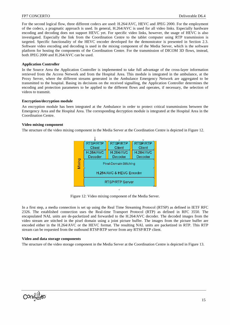
Video mixing component The structure of the video mixing component in the Media Server at the Coordination Centre is depicted in Figure 12.
Figure 12: Video mixing component of the Media Server.
In a first step, a media connection is set up using the Real Time Streaming Protocol (RTSP) as defined in IETF RFC 2326. The established connection uses the Real-time Transport Protocol (RTP) as defined in RFC 3550. The encapsulated NAL units are de-packetized and forwarded to the H.264/AVC decoder. The decoded images from the video stream are stitched in the pixel domain using a joint picture buffer. The images from the picture buffer are encoded either in the H.264/AVC or the HEVC format. The resulting NAL units are packetized in RTP. This RTP stream can be requested from the outbound RTSP/RTP server from any RTSP/RTP client.
Video and data storage components The structure of the video storage component in the Media Server at the Coordination Centre is depicted in Figure 13.

FP7 CONCERTO Deliverable D6.4
16
Figure 13: Video storage component of the Media Server.
Inbound RTP media streams are received over the RTP client after the connection has been established using RTSP. The received media streams are stored in MP4/SAF [1] for later replay. The replay can be requested from a dedicated RTSP/RTP client. A selected stream is also made available in the MPEG-DASH format for near-real-time viewing. Therefore, MPEG-DASH segmentation and encapsulation is performed and the Media Presentation Description (MPD) file is created. The replay can be requested from an MPEG-DASH client.
At the Coordination Centre, a MySQL database used to store 3D images in DICOM format is also implemented that can be accessed remotely by doctors.
Dedicated RTSP/RTP client Any compliant RTSP/RTP client (e.g., VLC Media Player) can be used to receive the RTP video streams from the Media Server. Both, the stitched streams and the individual streams can be received. The dedicated RTSP/RTP client developed (i.e., the Live Media Player) within CONCERTO provides some additional functionality. A content browser lists all available streams. This way, the available streams can be configured/updated in the Coordination Centre. The user (i.e., the medical staff) does not have to perform this task. Only the client device has to be connected to the server. Furthermore, when receiving the compound stream, tabbing one of the windows will establish a second connection for receiving the selected stream in full resolution.
MPEG-DASH client A standard-compliant MPEG-DASH client was developed. It can receive the video streams from the Media Server: the media stream is therefore transformed into the MPEG-DASH format at the Media Server. The stored media can be transformed immediately into MPEG-DASH format in order to allow near-real-time (delay of a few seconds) streaming as described above. The MPEG-DASH client receives the MPD file from the server and subsequently request media fragments based on the information in the MPD.
Cross-Layer signalling components The transmission of information between different modules of the platforms and different layers is performed through the use of two components, namely the Distributed Decision Engine (DDE) and the Network Information Service (NIS). A full description of these components is provided in Deliverable D2.3 [10]. Different instances of these components are present in the Emergency Area, in the Access Network and in the Hospital Area. Also a special, TCP socket-based cross-layer solution is applied between the flow mobility decision logic and the MIPv6-based execution scheme inside the mobile clients. This socket-based API is used to manage network layer mip6d-ng modules by the decision module working application layer.
Real-time quality meter The real-time quality meter module is composed by an application and a user interface developed for the Android operating system. Thanks to this component it is possible to measures the 2D/3D video quality perceived by users in real-time. The application is deployed in the Hospital Area and can be used to analyse and potentially influence (through feedbacks sent using cross-layer signalling) the quality of videos received in real-time or to evaluate the quality of recorded videos.
3D medical data rendering To allow the transmission of 3D medical data stored at the Coordination Centre, a rendering server is also implemented in a PC equipped with a GPU card. It implements a JPEG 2000 encoder and decoder, an H.264/AVC video encoder and decoder and an OpenGL-based volume rendering engine. At the client a web based GUI is equally implemented.
FP7 CONCERTO Deliverable D6.4
17
Flow mobility decision engine In order to optimize the transmission of the data generated in the BAN of the Source Area, a smartphone plays the role of aggregator and manages the transmission of the data through the flow mobility decision engine. The decision engine responsible for adaptive, flow-level mobility management is based on the well-known methodology of Analytical Hierarchy Process (AHP). The first step of AHP is the decomposition of the decision problem into a hierarchical structure. The first level presents the goal of the analysis, in this case the selection of the appropriate interface for the registered flows. Multi criteria parameters for cross-layer optimization (packet loss, delay, jitter, number of handovers, cost and bandwidth) are introduced by the second level. The third level contains the alternative choices (i.e., available network interfaces on the Smartphone device). The decision starts with the creation of a pair wise comparison matrix; each entry of this matrix presents the importance of criteria relative to each other. In the demonstration environment we consider the flows originated by the patient’s Smartphone device in the BAN and define the comparison matrices for all different data flows: one for the data stream provided by wearable sensors and one for video streaming. The second step is the calculation of the matrix of alternative option scores. Finally, the global score vector is calculated where the bigger global score indicates the better alternative of the decision problem. The flow mobility decisions can also be taken in a network-assisted or network controlled manner, taking advantage of the information collected through the extended capabilities of the DDE and NIS systems applied for cross-layer information exchange between the network and the mobile node.