Embed Size (px)
Citation preview

A100 USER GUIDE
Copyright and Disclaimer
All copyrights belong to Shenzhen fifotrack Solution Co., Ltd. You are not allowed
to revise, copy or spread this file in any form without consent of fifotrack.
is trademark of fifotrack, protected by law.
Please read this user guide carefully before installation to avoid any possible
personal injury or property loss.
Revision History
Version Author Revision Date Description of change
V1.1 Cici Wu August 17, 2015 Initial revision
Related Files
Version File Remarks
V1.2 <fifotrack A100 GPRS Protocol and Command List>
GPRS protocol between terminal and server, command details of GPRS/SMS/COM
V1.1 <fifotrack Parameter Tool User Guide> PC software tool for parameters configuration
V1.1 <USB Cable Driver Installation Guide> How to install USB cable driver
V1.1 <Firmware Upgrade Guide> How to upgrade firmware
Download link: http://www.fifotrack.com/Support/Userguide/
Related Software
Version Software Remarks
V1.0 < Parameter Tool > Parameter configuration tool on PC
V1.11.0 < PL2303_Prolific_DriverInstaller > Driver for USB cable
V1.0 < Firmware Upgrade Suite> Tool for firmware upgrade
Download link: http://www.fifotrack.com/Support/Userguide/
Copyright © fifotrack 2015 All rights reserved 2

A100 USER GUIDE
Contents
1 Product Overview ....................................................................................................... 4
2 Product Functions ....................................................................................................... 4
2.1 Tracking Functions ........................................................................................................... 4
2.2 Alarms .............................................................................................................................. 4
2.3 Other Functions ............................................................................................................... 5
3 Product and Accessories ............................................................................................ 5
3.1 Standard Packing Box ....................................................................................................... 5
3.2 Optional Accessories ........................................................................................................ 5
4 Product Appearance ................................................................................................... 6
5 PCB Overview and Hardware Design ......................................................................... 7
5.1 Hardware Design Highlight .............................................................................................. 7
6 LED Light ..................................................................................................................... 8
7 Specification ............................................................................................................... 8
8 First Use ...................................................................................................................... 9
8.1 Charging ........................................................................................................................... 9
8.2 Installing the SIM Card ..................................................................................................... 9
8.3 Installing GSM/GPS Antenna ......................................................................................... 10
8.4 Tracking by Calling ......................................................................................................... 10
8.5 SMS Reply Contents Example ........................................................................................ 11
8.6 Tracking by SMS Command - C01 .................................................................................. 12
8.7 Configuration by PC ....................................................................................................... 13
8.8 Platform Tracking ........................................................................................................... 13
9 Device Installation .................................................................................................... 14
9.1 I/O Installation ............................................................................................................... 14
9.2 Power/Ground Cable ..................................................................................................... 15
9.3 Positive/Negative Digital Input(IN1/IN2/IN3) .......................................................... 15
9.4 Analog Input( AD) .......................................................................................................... 15
9.5 Output control (out1/out2) ........................................................................................... 16
9.6 Installing Microphone or Speaker (Optional) ................................................................ 16
Copyright © fifotrack 2015 All rights reserved 3

A100 USER GUIDE
1 Product Overview
A100 is a multifunctional model which is suitable for fleet management, public transportation
management, school bus management, taxi operation management, vehicle insurance company
management, rent car management and private car antitheft, etc. It can integrate with different
sensors and collect the specific data as per customers’ requirements. Besides, A100 has core
functions to meet users’ demands, such as harsh acceleration/braking alarm, driving behavior
analysis, custom digital input, jamming detection, two-way calling and OTA. A100 uses own
FIFOTRACK GPRS PROTOCOL which is simple and practical, this enables the customers to integrate
on their own platform efficiently.
2 Product Functions
2.1 Tracking Functions
GPS+GSM Base Station Dual Tracking
Real Time Tracking
Time Interval Tracking
Distance Tracking
Direction Change Tracking
Mobile Phone Tracking
2.2 Alarms
SOS Alarm
GPS Antenna Cut Alarm
External Power Cut Alarm
Engine/Door Status Alarm
Maintenance remind
GEO-Fence Alarm
Speeding Alarm
Idling Alarm
Fatigue Driving Alarm
Harsh Acceleration Alarm
Harsh Braking Alarm
Parking Overtime Alarm
Copyright © fifotrack 2015 All rights reserved 4

A100 USER GUIDE
GPS Jamming Alarm
GSM Jamming Alarm
Internal Battery Low Alarm
External Battery Low Alarm
2.3 Other Functions
Stop Car Remotely Fuel monitoring
8 MB Flash Memory
Custom Digital Input
Detect ACC Status to Inhibit Static Drift
OTA
Uploading Mode Settings for ACC ON/ACC OFF
Roaming Time Interval Setting
Mileage And Running Time Settings
Voice monitoring (Optional)
Two-way Calling (Optional)
3 Product and Accessories
3.1 Standard Packing Box
Main Unit Wire GPS Antenna GSM Antenna
3.2 Optional Accessories
USB Cable Relay Microphone Speaker Copyright © fifotrack 2015 All rights reserved 5

A100 USER GUIDE
AS10 Fuel sensor AS20 ultrasonic fuel sensor
4 Product Appearance
Copyright © fifotrack 2015 All rights reserved 6

A100 USER GUIDE
5 PCB Overview and Hardware Design
5.1 Hardware Design Highlight
Protection for sudden-change of auto power supply: When the vehicle starts or is running, the
power voltage will have a wave of change. Our product supports voltage 11V-36V. When the
external power supply is below 10.5V, with low voltage detection, it will be automatically cut. When
external power supply is over 36V or has high voltage peak, the product will trigger high-voltage
protection through clamping, anti-pulse, and high voltage detection. This ensures the product to
operate normally under high voltage.
Auto power transient pulse: When the vehicle starts or is running, it will generate high-voltage
transient pulse with a range of hundreds of volts. If the product’s circuit is not well designed, it is
very easy to get damaged, and can’t be used. Through multistage transient pulse protection and
anti high-voltage surge protection, the product’s power circuit is well protected, and it can operate
stably.
Electromagnetic immunity: When the vehicle starts, the clock, RF, display screen and USB are very
easy to be interfered by electric spark, which causes the product to operate unstably. Through PCB
layout and ground wire handling, the product can work stably under interfered environment.
Anti static: The vehicle product’s working condition is complex. It is very easy to be influenced by
static, which causes damage to the product’s peripheral interfaces. Through ESD protection on
Copyright © fifotrack 2015 All rights reserved 7

A100 USER GUIDE
circuit and ground wire handling, the static in the range of 8KV-15KV won’t cause damage to
product. This ensures the product’s stability under complex working condition.
6 LED Light
GPS Light (Green) Off Power off or sleep Flash 0.1s on and 3S off GPS valid Flash every 0.1s GPS antenna cut Flash 2s on and 2s off No GPS signal On GPS module power problem GSM Light (Orange) Off Power off or sleep Flash 0.1s on and 3s off GSM available Flash every 0.1s Device is initialing Flash 2s on and 2s off No GSM External Power Light (Red) Off External power cut Flash every 0.1s External power low On External power normal
7 Specification
Item Specification Dimension 90*60*27mm Weight 140g GSM Module SIMCOM800 GPS Module U-blox7Q Input Voltage DC 11~36V/1.5A Internal Battery 600mAh/3.7V Power Consumption
30-35mA standby current
Internal Battery Life 100 hours in sleep mode, and 10 hours in normal working mode. Operating Temperature
-20℃~70℃
Humidity 5%~95% LED Light 3 LED lights indicating GPS/GSM/External power status Button/ Switch 1 SOS Button, 1 power switch Flash Memory 8MB (GPRS data 16000 units, SMS data 4000 units)
Copyright © fifotrack 2015 All rights reserved 8

A100 USER GUIDE
Sensor 3D Accelerator Sensor GSM Frequency Band
GSM 850/900/1800/1900MHz
GPS Sensitivity -161dBm GPS Start Speed Cold start 35s
Hot start 1s Position Accuracy 10m I/O Port 3 Digital inputs - 1 negative input, 1 positive input, 1 custom input
(Default positive input) 1 Analog input, voltage range is 0-30V 2 Output 1 Microphone port 1 Speaker port 1 USB port
8 First Use
8.1 Charging
First time use A100, please connect positive wire(+ Red) and ground wire(-black) to 12V or 24V
external power supply, charging device at least 2 hours, 3 hours is suggested. Before installation,
ensure all of the parameters setting and test are finished.
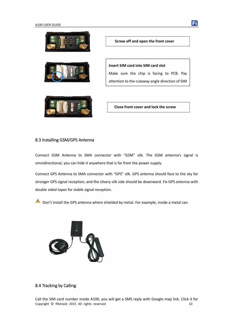
8.2 Installing the SIM Card
Device can’t support 3G or 4G network. Make sure the SIM card supports 2G.
Ensure the SIM card has enough balance.
Ensure PIN code has been closed.
Authorization SOS numbers can’t work well if SIM card doesn’t have caller ID service. E.g.:
device can’t reply SMS to authorization SOS number because SIM card can’t identify incoming
call.
SIM card should have GPRS function for platform tracking.
Turn off device before SIM card installation.
Copyright © fifotrack 2015 All rights reserved 9
A100 USER GUIDE
8.3 Installing GSM/GPS Antenna
Connect GSM Antenna to SMA connector with “GSM” silk. The GSM antenna’s signal is
omnidirectional, you can hide it anywhere that is far from the power supply.
Connect GPS Antenna to SMA connector with “GPS” silk. GPS antenna should face to the sky for
stronger GPS signal reception, and the silvery silk side should be downward. Fix GPS antenna with
double sided tapes for stable signal reception.
Don’t install the GPS antenna where shielded by metal. For example, inside a metal can.
8.4 Tracking by Calling
Call the SIM card number inside A100, you will get a SMS reply with Google map link. Click it for
Insert SIM card into SIM card slot
Make sure the chip is facing to PCB. Pay
attention to the cutaway angle direction of SIM
Close front cover and lock the screw
Screw off and open the front cover
Copyright © fifotrack 2015 All rights reserved 10

A100 USER GUIDE
specific map location.
8.5 SMS Reply Content Example
2015-09-04 07:44:28, 0km/h, Disconnect, A, EXPW:ON,http://maps.google.com/maps ?f=q&hl=en&q=loc:22.546510,114.079403 SMS Reply Format:
Copyright © fifotrack 2015 All rights reserved 11

A100 USER GUIDE
Field Detail Remarks 2015-09-04 07:44:28
Date and time, format YYMMDD hh:mm:ss
Date and time
0Km/h Speed is 0km/h Speed Disconnect GPRS disconnect GPRS connection status, ”disconnect” or
“connect”. A GPS fixed GPS Status,”A” means GPS valid, “V”
means GPS invalid. EXPW:ON External power on External power status. “ON” means
external power normal, ”OFF” means external power cut.
http://maps.google.com/maps ?f=q&hl=en&q=loc:22.546510,114.079403
Google map link, latitude in the front of longitude after ”Loc”. Unit degree Latitude=22.546510° Longitude=114.079403°
Google map link with latitude and longitude, which can be opened directly on smart phone.
8.6 Tracking by SMS Command - C01
SMS Command:000000,C01
SMS Reply: Current location
Note:Default SMS password is “000000”, set new SMS password with B10 command.
Please refer to <FIFOTRACK COMMAND LIST> for more details.
Copyright © fifotrack 2015 All rights reserved 12

A100 USER GUIDE
8.7 Configuration by PC
fifotrack company provide <FIFOTRACK PARAMETER TOOL> for configuration. Please download
USB cable driver and install it before using parameter tool. Refer to <USB CABLE DRIVER
INSTALLATION GUIDE> if need.
Connect A100 to PC with USB cable. Run “fifotrack Parameter Tool” software which will identify
port automatically and read all of the current parameters.
Please read <FIFOTRACK PARAMETER TOOL USER GUIDE> for more details.
8.8 Platform Tracking
You can use SMS commands B00, B01, B02, B03 to set server IP, port, APN and GPRS uploading
Copyright © fifotrack 2015 All rights reserved 13

A100 USER GUIDE
interval.
You can also set those parameters via parameter tool software on PC.
9 Device Installation
9.1 I/O Installation
I/O wire has 8 pins, including power, digital positive and negative inputs, output and analog input.
VCC IN2 IN3 OUT1
GND IN1 AD OUT2
I/O Color Function
VCC Red Positive power, connect to positive of vehicle battery, input voltage
range 11-36V
GND Black Ground, connect to negative of vehicle battery or the vehicle’s iron
part.
IN1 White Digital input1, negative input (default SOS button)
IN2 White Digital input2, positive input, default connect to ACC for status
detection.
IN3 White Digital input3, custom input, default positive.
AD Blue 12 bits analog input, supports voltage range 0-30V. Connect to
external sensor, eg,fuel sensor or temperature sensor.
OUT1 Yellow Output1
Output active: low level (0V)
Output inactive: open drain (OD)
Max open-drain (inactive) voltage: 45V
Copyright © fifotrack 2015 All rights reserved 14

A100 USER GUIDE
Max current for output low voltage (valid): 500mA
OUT2 Yellow Output2
Output active: low level (0V)
Output inactive: open drain (OD)
Max open-drain (inactive) voltage: 45V
Max current for output low voltage (valid): 500mA
9.2 Power/Ground Cable
9.3 Positive/Negative Digital Input (IN1/IN2/IN3)
9.4 Analog Input( AD)
Calculation formula:
Copyright © fifotrack 2015 All rights reserved 15

A100 USER GUIDE
AD Voltage=(AD)*3300*11/4096 Note:Original AD value is in hexadecimal. Convert it to decimal first, then use the formula.
9.5 Output control (OUT1/OUT2)
9.6 Installing Microphone or Speaker (Optional)
Please e-mail us at [email protected] if any question or feedback.
Copyright © fifotrack 2015 All rights reserved 16

