Embed Size (px)
Citation preview

01 03 0602 0504
07 09 1208 1110
Quick Start1. Connect AAT3 to Fieldpiece meter.2. Select mVDC range on meter.3. Remove vinyl slip cover from the
probe tip.4. Select desired switch position on
AAT3 for temperature, %RH, or airvelocity.
5. Read your measurement directly onthe display of the Fieldpiece meter.
CertificationsC-Tick (N22675)
CE
WEEE
RoHS Compliant
DescriptionYo u r A AT 3 i s a p o r t a b l e ,
psychrometer accessory head, with a built in hot wire anemometer.
The compact probe tip makes directly measuring in ducts a breeze. The 38"(96cm) telescopic probe with laser etched ruling and flattened edges allows you to locate proper measurement points within a duct and ensures that your probe is properly aligned for air velocity measurements.
The AAT3 can measure percent relative humidity, dry bulb, and air velocity and can calculate wet bulb and dew point.
The AAT3 snaps directly onto the Fieldpiece HS series DMMs. For other meters, use Fieldpiece ADLS2 test leads or AHDL1 handle adapter.
Use your AAT3 with the HVAC Guide to easily calculate in-duct CFM or to perform Target Evaporator Exit Temperature tests and get accurate Target Superheat calculations.
Go wireless with your AAT3 by using Fieldpiece wireless transmitters (ET2W/EH2W) to send measurements over-the-air to Fieldpiece wireless receivers (HG3, LT17AW, EH4W ) anywhere on the jobsite.
FieldpieceIn-Duct Psychrometer and Air Velocity Head Model AAT3
OPERATOR'S MANUAL
How to Use
General Instructions 1. Remove sensor cap from the telescopingprobe tip.2. Connect directly onto any FieldpieceHS multimeter, data logget or the HG3 HVACguide. For most Fieldpiece SC and LT meters, use Fieldpiece ADLS2 test leads plugged into the COM and VΩ jacks.3. Select mVDC range on multimeter.4. Set switch position of AAT3 to °F and°C,Ft/min and M/s, or %RH.
a.) For temperature set temp type switch to DRY BULB, WET BULB or DEW POINT.b.) For velocity measurements wait for 10 seconds as the AAT3 warms up.
5. Read the measurement directly onthe multimeter display.
What is Free Area? How Do I Get It?
Free Area is the total area through which air can flow on either a supply outlet or a return grille. Free area is also some times referred to as "effective area" or "see through area."
If there is no grille or restriction on the area through which air is flowing then the free area is equal to the actual area. This would be the case if you are performing an in-duct measurement or if you were to remove the grille from a supply or return.
If you are measuring airflow where there is an obstruction present then the free area is the total area minus area covered by the fins or grating.
Free Area is published by grille manufacturers and is the most accurate representation of the Free Area of a duct. Use manufacturer's data whenever available.
SpecificationsOperating environment: Air Velocity: -4°F to 140°F (-20°C to 60°C)Temperature: -4°F to 140°F (-20°C to 60°C)Relative humidity: 32°F to 131°F (0 to 55°C)Storage temp: -4°F to 140°F (-20°C to 60°C) <80%
R.H. (Batteries removed)Output impedance: approx. 1KΩTemperature coefficient: 0.1 x (specified accuracy)
per °C (<18°C or >28°C) (<64°F or >82°F)
AIR VELOCITYRange: 40-3940 ft/min (0.20-20.00 m/s)Note 1: To use full range AAT3 must be connected to a
DMM with a 4000 mVDC range or greater.Note 2: For m/s, divide the reading on the display by
10 for actual measurement. Tip: Move the decimal point one place to the left.
Accuracy: ± (5%+1 dgt) reading or ± (1%+1dgt)full scale.
RELATIVE HUMIDITYRange: 0% to 100% RHAccuracy:
±2.5% @ 73.4°F (23°C), 10% to 90% RH ±5% @ 73.4°F (23°C), <10% RH, >90% RHSensor Response Time: 60 seconds typical for 90%of total range.Sensor Hysteresis: ±1%RH typical
TEMPERATURE Range: -4°F to 140°F (-20°C to 60°C)Accuracy: ±1°F 32°F to 113°F
±2°F -4°F to 32°F, 113°F to 140°F±0.5°C 0°C to 45°C±1°C -20°C to 0°C, 45°C to 60°C
Sensor type: Air velocity: Tiny glass bead thermistor.Relative Humidity: Capacitance polymer film.
Temperature: Precision thermistor.Battery: 9VBattery life: 20 -35 hours typicalBattery indication: Red Lo Batt LEDAuto Power off: after 15 minutes of inactivity if APO
is active.Dimensions: 144mm(H) x 67mm(W) x 32mm(D).Weight: approx. 240g including battery.
MaintenanceClean the exterior with a dry cloth.
Do not use liquid.
Battery ReplacementWhen Lo Batt LED lights up replace
old battery with new 9V battery.
Sensor CareWhen not in use it is best to protect
this sensors with the vinyl slip cover included with the AAT3.
Extreme conditions or exposure to solvent vapors may offset the RH% sensor. If this happens, place the sensor in a controlled envrionment of 75%RH and between 68°F - 86°F for a period of 24 hours.
To create a 75%RH environment moisten a small amout of table salt, in an open container such as a clean 2 liter bottle cap.
Place the container with the salt solution and the AAT3 probe in a sealable plastic bag, and leave the bag in a room temperature location where it will not be disturbed for 24 hours.
Note: It is important that the salt solution does not come in direct contact with the sensor, as this may permenantly damage the sensor.
Optional accessories
RCONE1 and AAT3 working with ET2W and HG3 to wirelessly log Wetbulb for target superheat testing.
80
AAT3
In-DuctPsychrometer& Air VelocityHead
ON
LO BATTAVG
ENGLISH
ENGLISH METRIC
RH%Ft/min
°F
RH%M/s°C
METRIC
DRY BULBWET BULB
DEW POINT
AVG
NORMAL
AUTO OFF
Limited WarrantyThis meter is warranted against
defects in material or workmanship for one year from date of purchase. Fieldpiece will replace or repair the defective unit, at its option, subject to verification of the defect.
This warranty does not apply to defects resulting from abuse, neglect, accident, unauthorized repair, alteration, or unreasonable use of the instrument.
Any implied warranties arising from the sale of a Fieldpiece product, including but not limited to implied warranties of merchantability and fitness for a particular purpose, are limited to the above. Fieldpiece shall not be liable for loss of use of the instrument or other incidental or consequential damages, expenses, or economic loss, or for any claim of such damage, expenses, or economic loss.
State laws var y. The above limitations or exclusions may not apply to you.
For ServiceI n t h e U S A , c a l l Fi e l d p i e ce
Instruments for one-price-fix-all out of warranty service pricing. Send check or money order for the amount quoted. Send the meter freight prepaid to Fieldpiece Instruments. Send proof of date and location of purchase for in-warranty service. The meter will be repaired or replaced, at the option of Fieldpiece, and returned via least cost transportation. Outside of the USA, please visit www.fieldpiece.com for service contact information.
AAT3 w/ ET2W
transmitting
wirelessly to HG3
ARH5
In-Duct PsychrometerHead
ON
AUTO OFF
1%RH/mVDC1°F/mVDC1°C/mVDC
LO BATT
DEW POINT%RH
WET BULBTEMP
°F
°C
ON
OFF
ET2W
LO BATT
SEND
RECEIVE
ON
ACDC
WirelessTransmitter
SYNC
Clear
Input Output
Recall
Enter
Save
Sync
SETUP
TargetEvaporator
Logger
Light
Exit Temp
CFM
Display
Superheat
SubcoolingCombustion
HVAC Guide
CheckMe!
Fieldpiece HG3
Data
Service
TargetTargeTargeargetrgetgetgetEvapororratoratoratortatoratorato
Exit TExitExitExE e
TarEvaporat
t Temp
INPUT FORMSH Table: Standard
Refrigerant: R-22
OD Dry Bulb: 85.4°F
Return WB: 63.0°F
SL Pressure: 52.4psig
SL Temp: 45.4°F
CustomerID: __JONES123
ET2W
LO BATT
SEND
RECEIVE
ON
ACDC
WirelessTransmitter
SYNCClear
Input Output
Recall
Enter
Save
Sync
SETUP
TargetEvaporator
Logger
Light
Exit Temp
CFM
Display
Superheat
SubcoolingCombustion
HVAC Guide
CheckMe!
Fieldpiece HG3
Data
Service
EExit TExitExiEx e
TargetargetargetrgetrgetgeTargeoratoratoatoratorator
TarEvaporat
t Temp
INPUT FORMSH Table: StandardRefrigerant: R-22OD Dry Bulb: 85.4°FReturn WB: 63.0°FSL Pressure: 52.4psigSL Temp: 45.4°FCustomerID: __JONES123
AAT3
In-DuctPsychrometer& Air VelocityHead
ON
LO BATTAVG
ENGLISH
ENGLISH METRICRH%
Ft/min°F
RH%M/s°C
METRIC
DRY BULBWET BULB
DEW POINT
AVG
NORMAL
AUTO OFF
99 Washington Street Melrose, MA 02176 Phone 781-665-1400Toll Free 1-800-517-8431
Visit us at www.TestEquipmentDepot.com
13 15 1814 1716
19 21 2420 2322
Diagnostic TestsWireless Return Wet Bulb for Target Superheat
The AAT3 with a wireless transmitter (ET2W, EH4W, or LT17AW) allows to you monitor the return wet bulb while you are at the condensor. Send this real-time WB measurement wirelessly to the INPUT FORM of the HVAC Guide (HG3) to calculate a real-time target superheat.1. Sync your transmitter with AAT3 to
the Return WB INPUT line in Super-heat Test of the HG3.
2. Punch or drill a small 3/8" hole inthe return plenum to insert AAT3probe. Press ENTER on the HG3 tolock reading.
3. Input an outdoor dry bulb manually or with an ATH4 at the consdensorinto the OD Dry Bulb INPUT line inthe Superheat Test of the HG3.
4. Press OUTPUT on HG3 to see yourtarget superheat calculations.
return and selecting the appropriate switch position on the AAT3. Press ENTER to lock reading.
4. In the INPUT FORM, highlight Sup-ply DB. Press ENTER to measure air temperature coming out of theevaporator. Punch or drill a small 3/8" hole in the supply plenum and insert ARH5 wand in the center of the plenum to take measurement.Press ENTER to lock reading.
5. Press OUTPUT to view results.
Measuring Accurate Airflow
Find a Suitable Location for a Traverse
1. The cross sectional area at, before and after the traverse location should be a either rectangular or round.
2. Make sure you have sufficient access around the traverse location so that the duct may be traversed at multiple angles.
3. The traverse location should be chosen so as to minimize the effects of leaks in the portion of the system between the fan and the traverse location.
4. The traverse location should be located far enough downstream of the fan to allow the airflow to come to a uniform distribution. To determine an effective length, assume a minimum of 2.5 duct diameters for 2500 ft/min or less and add 1 duct diameter for each additional 1000 ft/min measured. (For a rectangular duct the equivalent diameter can be calculated as D=√(4hw/π) where “h” is the height of the duct and “w” is the width.)
5. Locations directly downstream from obstructions, bends or sudden changes in the duct are not good locations for a traverse.
Execute the Traverse1. Determine the appropriate measurement
points by measuring either the diameter of the duct or the width and height. Then use the appropriate table (See table 1 and 2) to calculate the insertion depth where each of the point measurements should be recorded.
2. Set the average switch on the AAT3 to AVG to display a 16 second running average.
3. Insert the probe tip of the AAT3 into the duct and use the flat edges of the probe to align the sensor with the airflow direction. Check that the direction of airflow is at 90° to the probe by making sure that the probe is at a right angle to the side of the duct.
4. Use the laser etched ruler on the side of the probe probe to measure the insertion depth and find the locations you determined in step 1.
5. Record a point measurement (Either manually or by using the Fieldpiece HG3, or DL3) at each of the locations determined in step 1.
6. Use the recorded velocity measuremtents to calculate the airflow by first detemining the average velocity of the traverse and then multiplying by the free area of the duct.
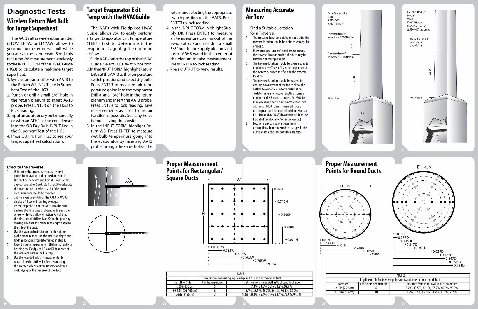
Proper MeasurementPoints for Rectangular/Square Ducts
TABLE 1Traverse locations using log-Tchebycheff rule in a rectangular duct
Length of Side # of Traverse Lines Distance from Inner Wall in % of Length of Side< 30 in (76 cm) 5 7.4%, 28.8%, 50%, 71.2%, 92.6%
30-63in (76-160cm) 6 6.1%, 23.5%, 43.7%, 56.3%, 76.5%, 93.9%>63in (160cm) 7 5.3%, 20.3%, 36.6%, 50%, 63.4%, 79.9%, 94.7%
Proper MeasurementPoints for Round Ducts
TABLE 2
Log linear rule for traverse points on two diameter for a round ductDiameter # of points per diameter Distance from inner wall in % of diameter
<10in (25.4cm) 6 3.2%, 13.5%, 32.1%, 67.9%, 86.5%, 96.8%≥ 10in (25.4cm) 10 1.9%, 7.7%, 15.3%, 21.7%, 36.1%, 63.9%
Target Evaporator Exit Temp with the HVACGuide
The AAT3 with Fieldpiece HVAC Guide, allows you to easily perform a Target Evaporator Exit Temperature ( TEET ) test to determine if the evaporator is getting the optimum airflow.1. Slide AAT3 onto the top of the HVAC
Guide. Select TEET switch position.2. In the INPUT FORM, highlight Return
DB. Set the AAT3 to the Temperature switch position and select dry bulb. Press ENTER to measure air tem-perature going into the evaporator Drill a small 3/8" hole in the returnplenum and insert the AAT3 probe. Press ENTER to lock reading. Takemeasurements as close to the airhandler as possible. Seal any holesbefore leaving the jobsite.
3. In the INPUT FORM, highlight Re-turn WB. Press ENTER to measurewet bulb temperature going intothe evaporator by inserting AAT3probe through the same hole at the
90°
D (<10”)
D (>10”)
W
H
0.032D0.135D
0.321D0.679D
0.865D0.968D
0.019D0.077D
0.153D0.217D
0.361D0.639D
0.061W0.235W
0.437W0.563W
0.765W0.939W
0.926H
0.712H
0.500H
0.288H
0.074H
0.783D0.847D
0.923D0.981D
90°
D (<10”)
D (>10”)
W
H
0.032D0.135D
0.321D0.679D
0.865D0.968D
0.019D0.077D
0.153D0.217D
0.361D0.639D
0.061W0.235W
0.437W0.563W
0.765W0.939W
0.926H
0.712H
0.500H
0.288H
0.074H
0.783D0.847D
0.923D0.981D
90°
D (<10”)
D (>10”)
W
H
0.032D0.135D
0.321D0.679D
0.865D0.968D
0.019D0.077D
0.153D0.217D
0.361D0.639D
0.061W0.235W
0.437W0.563W
0.765W0.939W
0.926H
0.712H
0.500H
0.288H
0.074H
0.783D0.847D
0.923D0.981D
90°
908580
90°90
85
80
2.5
D1
D
Traverse here if velocity is 2500ft/min
Traverse here if velocity is 3500ft/min
FAN
Ex. 8” round ductD=8”2.5D=20“2.5D+1D=28”
*Not to Scale
2.5
D
Ex. 24”x 8” ductH=24W=8D=√(4HW/π)D=16” (approx.)2.5D= 40” (approx.)
Traverse here if velocity is 2500ft/min
*Not to Scale