Embed Size (px)
Citation preview

Fieldbus Access Revision 1.5
Getting Started Date: 2017-01-09
Getting Started
www.crosscontrol.com
Fieldbus Access

Fieldbus Access Revision 1.5
Getting Started Date: 2017-01-09
www.crosscontrol.com
Contents Revision history ..................................................................................................................................2
Glossary ..............................................................................................................................................2
1. Brief Introduction ..........................................................................................................................3
2. Configuration Tool ........................................................................................................................4
2.1. Fieldbus Access Configuration Tool ....................................................................................... 4
2.1.1. Configuration – Left Column ....................................................................................... 5 2.1.2. Configuration – Middle (Wide) Column .................................................................... 5 2.1.3. Configuration – Right Column .................................................................................... 5 2.1.4. Generate configuration file ........................................................................................ 5
3. Simple Example............................................................................................................................6
3.1. Manage can bus settings and signals................................................................................... 6
3.2. Use our signals in the gui application (Quick/QML) ........................................................... 9
3.3. Use our signals in the gui application (Widget) ................................................................. 10
3.4. Run the example in development VM ................................................................................ 11
3.5. Signalvalue explained ............................................................................................................ 13
3.6. Scaling of values ...................................................................................................................... 13
3.7. Run the example on a CCpilot ARM device. .................................................................... 14
4. FAQ ..............................................................................................................................................17
4.1. How do I log in to my device ................................................................................................ 17
4.2. Application running but no value is updated ................................................................... 17
4.3. Application not starting on device ...................................................................................... 17
4.4. How to verify that LinX-Base runtimes is installed on Device .......................................... 17
4.5. Is Data Engine running ............................................................................................................ 17
4.6. Is Fieldbus Access runtime running ....................................................................................... 17
4.7. Manual start of FieldbusAccess or DataEngine................................................................. 17
4.8. Not sure if FieldbusAccess starts with my Configuration file ............................................ 18
Revision history
Rev Date Author Comments
1.0 2016-06-10 D. Nisses-Gagnér First Version
1.1 2016-11-08 D. Nisses-Gagnér Review for FA 1.0.0 patch release
1.2 2016-11-17 D. Nisses-Gagnér Workshop findings - update
1.3 2016-12-16 D. Nisses-Gagnér Merge Conf Tool info from Quick guide
1.4 2016-12-30 D. Nisses-Gagnér Update/clairification of example + FAQ
1.5 2017-01-09 D. Nisses-Gagnér Added Widget based example
Glossary
Word/Abrevation Explanation
CrossTecc A set of applications and components...
crc Cyclic redundancy check
SAP Software Application Platform
Qt Development framework qt.digia.com
RTE RunTime Environment
API Application Programming Interface
VDM Virtual Development Machine
VM Virtual Machine
GUI Graphical User Interface

Fieldbus Access Revision 1.5
Getting Started Date: 2017-01-09
www.crosscontrol.com
1. Brief Introduction
Fieldbus Access is a communication
bridge containing the implementation of
the most widely used vehicle fieldbuses
(incl. J1939 and CANopen) and enables
all other LinX Software Suite modules to
use them with an easy-to-use interface.
The Fieldbus Access UX configuration
tool provides an easy interface to
manage fieldbuses and which signals to
use in your application.
Accessing CANbus signals from your
GUI application is simple. Install the
FieldbusAccess runtime in the LinX
Software Suite development VM and on
your target device. Packages are found
from our support site,
http://support.crosscontrol.com/%20d
ownloads/LinX_Software_Suite
From your GUI application you connect
and access your signals as before via
Data Engine. With the added Fieldbus
Access runtime you have accessibility to
the can-bus signals. Mapping between
DE signals and can-bus signals is simply
done from our configurator that is
integrated in the development tool.
The configurator tool, further explained later in this documentation, generates a configuration file
that is used both from the development environment and from the deployed GUI application. Also
all code connecting and creating signals from the GUI application is now generated and
automatically assigned your GUI project from the integrated tool. Booth QML and Widget based
code is supported. This enables code completion within your projects. Simply setup your signals
from the graphical configuration tool and then you are fully set to use these signals in your
applications.
Figure 1 Signalflow between components

Fieldbus Access Revision 1.5
Getting Started Date: 2017-01-09
www.crosscontrol.com
2. Configuration Tool
2.1. Fieldbus Access Configuration Tool
A QtCreator plugin, User Interface, managing the setup and configuration of CAN/DE Signals of
the system. Aside from generating configuration files for fieldbus layer, this configuration tool can
auto generate the communication layer between your Qt application and Data Engine, exposing
your configured signals to QML and widgets with a single mouse click.
Files generated by the Fieldbus Configuration Tool:
• qtobserver.h
• qtobserver.cpp
• dataenginebase.h
• dataenginebase.cpp
• dataengine.h
• dataengine.cpp
Since these files are overwritten every time the linked fieldbus configuration is changed, it is not
recommended to make any custom edits to these files. Sub-class the DataEngine class
(dataengine.h) and override relevant parts instead. If you do so, remember to expose your own
derived class to QML or your widgets, instead of the default one.
From the configuration tool you have full access to the SAE J1939-71 standard signal library.
Simply search and click drag in desired signals to your configuration. Some information such as bit-
position, length etc. will be prefilled, other will be filled with an explanatory text and marked with
red to indicate user configuration (cycle time etc.).
Figure 2 FA Configuration Tool
Figure 2b File menu

Fieldbus Access Revision 1.5
Getting Started Date: 2017-01-09
www.crosscontrol.com
2.1.1. Configuration – Left Column
On the top left side we will find menu buttons used to open/close/save etc. the configuration file.
We also find the basic configuration with Busses as root and Signals on second level. Signals are
grouped in TX (Transmit from GUI application to CAN bus) and RX (Receive from CAN bus to GUI
application). PGN signals are expandable and holds its SPN’s underneath.
2.1.2. Configuration – Middle (Wide) Column
In the wide middle column you find more information and are also able to change different
settings. By clicking on the bus (left column) will bring up configuration of the bus in the middle
view. Here you are able to set bus number, baud rate, node identifier name etc. If clicking instead
on some of the signals (left column) will change the view in the middle where configuration of
signals are possible (similar to picture above). PGN/SPN Byte/Bit position are indexed between 0-
7. Raw can-messages uses Gain 1.0 with Offset 0.
2.1.3. Configuration – Right Column
Standard J1939-71 signal library are found in the right column. Search and filter the signals for an
easy overview of the signals you need and then drag them to the left for configuration. This
configuration is stored in a cvs file and you are able to create and use your own custom library for
convenient use in all your projects.
2.1.4. Generate configuration file
When you are done configuring desired signals and can busses, save the file and Link to your
application project. A .json configuration file are created and also some cpp code is generated that
is used to create and link your application to data engine.

Fieldbus Access Revision 1.5
Getting Started Date: 2017-01-09
www.crosscontrol.com
3. Simple Example
A normal workflow could look something similar to this example. The LinX Software Suite -
Getting Started.pdf guide found on our supportsite explains further how to setup a project and
compile/deploy and execute on target.
3.1. Manage can bus settings and signals
Create/open your GUI application.
In the menu press File->New File or Project
We use the mtcc QML template in this example.
Name your project and save it (usually /home/ccs/qt/MyProjects )
Kit Selection, chose CCpilot ARM Qt5 Development and Virtual Development Qt5
For resolution, refer to your devices technical manual. This can be changed manually in
your project later!
Figure 3 mtcc QtQuick (QML) template
Figure 4 Quick project from template

Fieldbus Access Revision 1.5
Getting Started Date: 2017-01-09
www.crosscontrol.com
Switch back to Fieldbus Access Configuration tool and setup/manage your signals. Add a
can bus and then PGN/SPN signals. SPN signals will be mapped 1to1 with DE signals with
the name entered in “DE Signals” column for every SPN. For this example create a
configuration looking something like this!
In the library window (right panel), search for Engine speed and then drag PGN
65119 (0xFE5F) to RX Signals on the left panel. It is also possible to drag PGN or SPN
from the library to the middle info panel (if TX/RX tab is selected).
For easier overview when we test the application later we change the Trans. Mode to
On Change (default for this signal is cyclic).
Double click on cyclic and choose “change_of_state” from the drop down.
Figure 5 Example of some added signals
Link this configuration to your newly created GUI application. .
The tool will automatically recognize what project you currently have active and link the
configuration to that. If you have many projects open and switches between them the
signal configuration will change according to what file you have linked. If you have
problems linking your project, make sure that you have one of the files in the active
project selected (Qt Edit menu).
By linking a configuration some new files are included and added to your project. I choose
to create a new subfolder under my project (DataEngine) but if you like you can have the
files created in the root source folder of your project or any other substructure you prefer.
Clicking the link icon will bring up the Project Link Dialog (description follows below)

Fieldbus Access Revision 1.5
Getting Started Date: 2017-01-09
www.crosscontrol.com
Figure 7 Project Link Dialog
Project type: Let’s you choose between QML/Widget. This is used by the wizard to create
correct data engine backend classes to the application we are creating.
DataEngine context: Choose between Root context/QML object or pure C++ classes. This
defines how the linking between the backend and frontend is created. (Widget projects
uses C++ classes only).
Transmit signal filter: Transmit all/Transmit on change. If signals sould be transmitted to DE
every time or only when the value changes.
Update policy: On Save/Manual Only. Changes in the configuration tool (adding new SPN
to the file etc.) will generate new code to your application. This options automaticaly
creates this code when you save the configuration file or manually.
DataEngine class location: Where the generated class files will be stored (typically your
project folder location or subfolder).
Config file location: Storage of the configuration file. Store configuration files in project
application folder
After linking dialog, switch back to Edit mode in Qt.
We find auto created files added in DataEngine directory (or in the folder we choose in
the linker dialog). Our configured signals are now available within our project. By simply
changing our configuration file in the tool and save it, these classes will automatically
update and make sure you have a connection to data engine. In dataengine.h we find
our added SPN signals from the configuration.
Figure 8 Example project linked with our configuration file.
Fieldbus Access Revision 1.5
Getting Started Date: 2017-01-09
www.crosscontrol.com
3.2. Use our signals in the gui application (Quick/QML)
In main.cpp you find the following code
qmlRegisterUncreatableType<DataEngine>("maximatecc",1,0,"DataEngine", ”Don’t instance DataEngine”);
engine.rootContext()->setContextProperty("dataEngine", &dataEngineContext);
This code will register your newly created DataEngine class for easy access in your qml
code. We may now change our main.qml to display one of our receiving signals.
The code in main.cpp will instantiate our DataEngine class for us so we may use it in our
qml-file.
If we want to display an incoming signal value in the application we can use the default
text filed that currently displays our project name and change it to our value.
In the Text block in main.qml, replace (row 34) from
text: "Tutorial"
Tutorial is the project name, if you have named your application otherwise that will be
shown here.
Replace with
text: dataEngine.EngineSpeed
dataEngine is the signal manager runtime and after you type dataEngine.E there will be a
dropdown list with available signals from your configuration for easy auto completion.
The application will display the value of EngineSpeed signal whenever received on the
can-bus.

Fieldbus Access Revision 1.5
Getting Started Date: 2017-01-09
www.crosscontrol.com
3.3. Use our signals in the gui application (Widget)
If you instead of QML choose a widget based application the data engine context takes
pure c++ classes only. The wizard does not update main.cpp for widget applications.
To connect a fieldbus value to a widget, please follow these steps.
Add a LCD Number Widget to your ui file (application.ui)
Next step is to instantiate the DataEngine class so we have access to our signals.
In application.cpp, add
#include “DataEngine/dataengine.h” row 3
DataEngine *de = new DataEngine(); row 13
connect(de, SIGNAL(EngineSpeedChanged(int)), ui->lcdNumber,
SLOT(display(int))); row 15
The application will display the value of EngineSpeed signal whenever received on the
can-bus.

Fieldbus Access Revision 1.5
Getting Started Date: 2017-01-09
www.crosscontrol.com
3.4. Run the example in development VM
To verify that the application runs we will setup the environment in our VM and start the
application there. First we will make sure that the DataEngine and FieldbusAccess runtime are
running. On the VM Desktop you find ICONS for quick access.
Start “Firebird DB startup” (Starts the persistant signals db server). If you are prompted to
enter a password you should enter “default”. The DataBase server will start and run in the
background.
Start “DataEngineServer”, you can start it from the desktop shortcut or open a new console
and run following command
# /opt/bin/dataengineserverApp --debug
This will display current DataEngine version and what ip:port you are running on.
Before we start the fieldbusaccess runtime we need to make sure that we have our CAN-bus
interface running in our VM. Included in the runtime-installation package there is a script that sets
up a virtual CAN interface.
# /home/ccs/setupVCAN can0
To verify that the interface is running you could run
# ifconfig
This will show something like
can0 Link encap:UNSPEC HWaddr 00-00-00-00-00-00-00-00-00-00-00-00-00-00-00-00
UP RUNNING NOARP MTU:16 Metric:1
RX packets:5 errors:0 dropped:0 overruns:0 frame:0
TX packets:5 errors:0 dropped:0 overruns:0 carrier:0
collisions:0 txqueuelen:0
RX bytes:30 (30.0 B) TX bytes:30 (30.0 B)
Next step is to start our fieldbusaccess runtime and that requires our configuration file we created
earlier in the example section. Open a new console and start the runtime with following command
(add path and filename to your configuration file as argument),
# /opt/bin/fieldbusaccess /home/ccs/qt/MyProject/tutorial/
FA_Signal_Configuration.json
fieldbusaccess takes a configuration file of format json as it’s
first argument, this is the only required argument. type
fieldbusaccess –h for further help.
Fieldbus Access Revision 1.5
Getting Started Date: 2017-01-09
www.crosscontrol.com
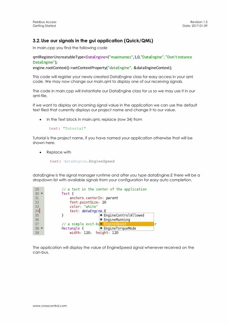
In the end of the debug information you will find a list of the signals from the configuration file.
Every SPN creates a unique data engine signal.
SPN in receive list: 65119:FE5F:2008
o 65119 PGN in decimal form
o FE5F PGN in hex form
o 2008 Data Engine signal index
Now it’s time to start our application from QtCreator. Initially we will have a black screen with a
grey Exit button on the upper right corner and a signal value in the middle. To simulate sending a
can-signal we can use a tool called cansend in the VM. In a new console window, install the toolkit
with
# sudo apt-get install can-utils
Send a can message with following command
# cansend can0 18FE5F08#1111111111111111
This will produce the signal value 546 in DataEngine index 2005 and will now be shown in our
application.
Figure 10 Demo application with value sent from can-bus

Fieldbus Access Revision 1.5
Getting Started Date: 2017-01-09
www.crosscontrol.com
3.5. Signalvalue explained
We are sending a 8 byte value with 0x11 {0001 0001} as value in every byte.
{0001 0001} {0001 0001} {0001 0001} { etc.
In the config file we find that signal EngineSpeed is mapped on byte 3, bit 0 with length 16.
Byte index 3 Byte index 4 Byte index 5
{0001 0001} {0001 0001} {0001 0001}
0001 0001 0001 0001 = 0x1111 = 4369 dec
Scaling this value with Gain 0,125 and offset 0 we get 4369*0.125+0 = 546,125
Since we send it as a DataEngine INT value the number is truncated to 546
3.6. Scaling of values
Many signals in J1939 library is scaled according to configuration. In the configuration tool you will
set this information in the Gain and Offset fields. The sent values will be scaled with the following
formula
rawValue * gain + offset
To send raw can values set gain to 1 and offset to 0.
Fieldbus Access Revision 1.5
Getting Started Date: 2017-01-09
www.crosscontrol.com
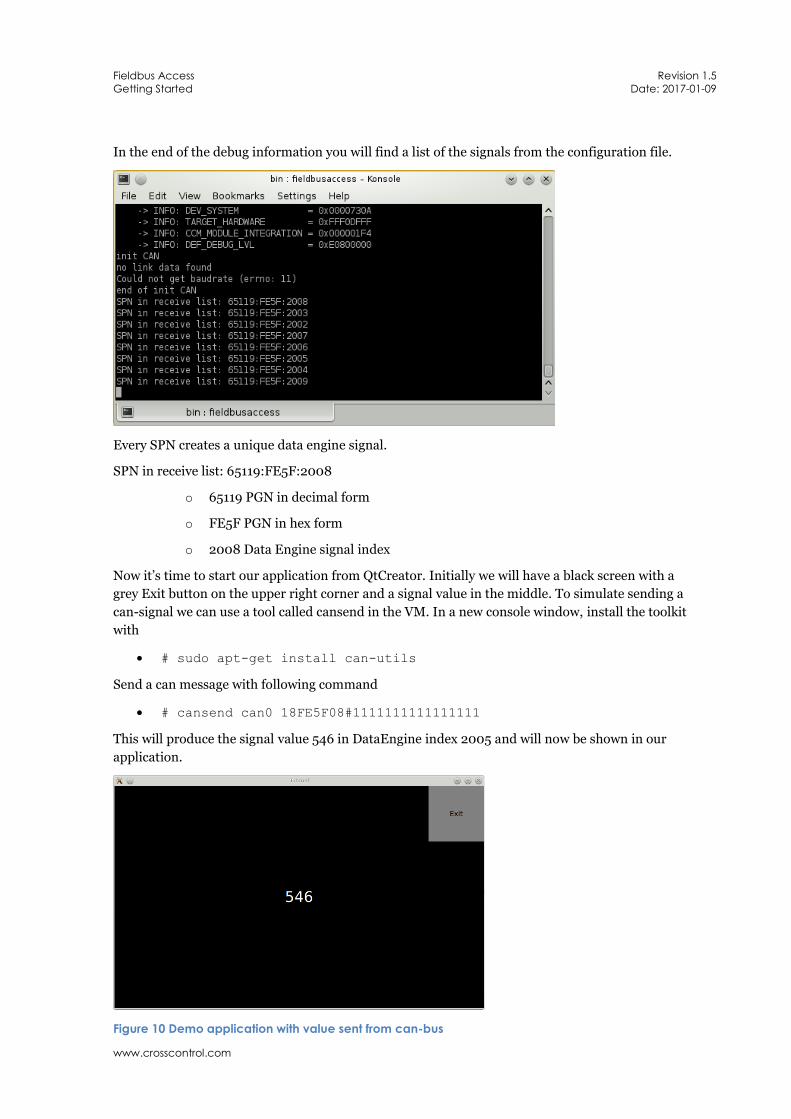
3.7. Run the example on a CCpilot ARM device.
Make sure that your CCpilot device is prepared for running fieldbus access, Data Engine version
3.0.1 or newer and LinX-Base 2.1.0 or newer is required. Install the
LinX-Base_VA_device_v2.1.0.run (or latest version) found on our support site.
http://support.maximatecc.com/downloads/LinX_Software_Suite
Change the /opt/bin/FieldbusAccess_ConfigFile.json to point to your deployed configuration
connected to your project.
# ssh root@<ipaddress> (pw:suseroot)
# ln –sf /opt/tutorial/bin/FA_Signal_ConfigFile.json
/opt/bin/FieldbusAccess_ConfigFile.json
reboot
After reboot of your CCpilot the dataengine and fieldbusaccess runtime will automatically start.
Manual stop/start of LinX runtimes are done with following commands
/opt/etc/init.d/StartupDataEngineServer stop/start
/opt/etc/init.d/StartupFieldbusAccess stop/start
Next we will deploy our GUI to a CCpilot device. Change the build configuration in QtCreator to
ARM.
Figure 61 Project settings in QtCreator
Fieldbus Access Revision 1.5
Getting Started Date: 2017-01-09
www.crosscontrol.com
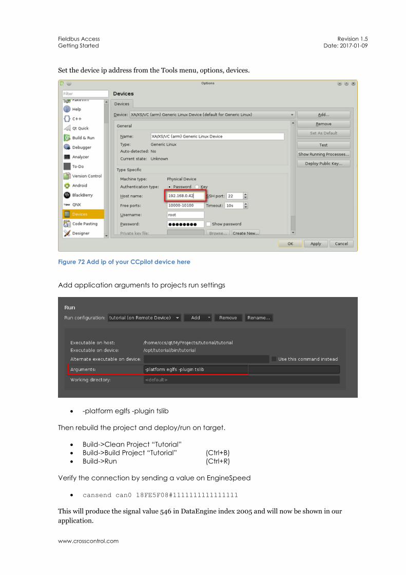
Set the device ip address from the Tools menu, options, devices.
Figure 72 Add ip of your CCpilot device here
Add application arguments to projects run settings
-platform eglfs -plugin tslib
Then rebuild the project and deploy/run on target.
Build->Clean Project “Tutorial”
Build->Build Project “Tutorial” (Ctrl+B)
Build->Run (Ctrl+R)
Verify the connection by sending a value on EngineSpeed
cansend can0 18FE5F08#1111111111111111
This will produce the signal value 546 in DataEngine index 2005 and will now be shown in our
application.

Fieldbus Access Revision 1.5
Getting Started Date: 2017-01-09
www.crosscontrol.com
Figure 10 Demo application with value sent from can-bus (QML)
Figure 11 Demo application with value sent from can-bus (Widget)

Fieldbus Access Revision 1.5
Getting Started Date: 2017-01-09
www.crosscontrol.com
4. FAQ
4.1. How do I log in to my device
From console in your virtual machine
ssh root@<ipaddress> (pw: suseroot)
4.2. Application running but no value is updated
Check that dataengineserverApp, fieldbusaccess and your application is running
ps (if one of above runtime is not found in the processes list try start them manually)
ifconfig can0 should be shown in the list of network interfaces.
Verify that correct node id’s and addresses is configured in the configuration file
4.3. Application not starting on device
On the device, execute following command,
ldd <Application Name>
If you get “not a dynamic executable” your binary is compiled for another platform. Try to change
build kit in your project settings.
4.4. How to verify that LinX-Base runtimes is installed on Device
On the device, execute following command,
ls /opt/packages In the list of installed components you should see “LinX-Base_VA_device_v2.1.0”
4.5. Is Data Engine running
On the device, execute following command,
ps | grep dataengineserverApp
2024 root 118m S /opt/bin/dataengineserverApp
4.6. Is Fieldbus Access runtime running
ps | grep fieldbusaccess
2409 root 38068 S /opt/bin/fieldbusaccess /opt/bin/FieldbusAccess_Config
4.7. Manual start of FieldbusAccess or DataEngine
Log in to the device and execute following command
/opt/etc/init.d/StartupDataEngineServer {start|stop}
/opt/etc/init.d/StartupFieldbusAccess {start|stop} o FieldbusAccess will start with the default /opt/bin/FieldbusAccess_Configfile.json
as it’s argument if none is given.
Manual start of Fieldbus Access runtime with arguments,

Fieldbus Access Revision 1.5
Getting Started Date: 2017-01-09
www.crosscontrol.com
/opt/bin/fieldbusaccess /path_to_application_config/config_name
/opt/bin/fieldbusaccess -h (for additional help)
4.8. Not sure if FieldbusAccess starts with my Configuration file
On the device, execute following command,
ps | grep fieldbusaccess
2409 root 38068 S /opt/bin/fieldbusaccess /opt/bin/FieldbusAccess_Config
Fieldbus Access runtime is running with /opt/bin/FieldbusAcces_ConfigFile.json as it’s
configuration file.
ls -l /opt/bin/FieldbusAccess_ConfigFile.json
/opt/bin/FieldbusAccess_ConfigFile.json ->
/opt/Tutorial/bin/FieldbusAccess_ConfigFile.json
The link /opt/bin/FieldbusAccess_ConfigFile.json points to your configuration
-> /opt/Tutorial/bin/FieldbusAccess_ConfigFile.json
Another way to make sure what configuration file is executed by Fieldbus Access is to run it
manually.
/opt/etc/init.d/StartupFieldbusAccess stop
/opt/bin/fieldbusaccess /path_to_application_config/config_name &
This starts Fieldbus Access runtime and a short summary of the configuration parsed is shown in
the start of the output
o Number of can-bus connections
o Number of mappings (PGN’s)
o Number of SPN’s
o List of PGN’s connected to Data Engine