Embed Size (px)
Citation preview
Part Lists Great Plains Manufacturing, Inc. 1
Update InstructionsAir-Pro® Field Update Kit
Used with Planter models:
• Recommended update for all 2011 and earlier bulk-fillair-seed-delivery Yield-Pro® planters with Air-Pro®
seed meters. This includes 2011- Models 3PYPA,YP1225A, YP1625A, YP2425A, YP3025A, YP4025Aand YP4425A.
General Information
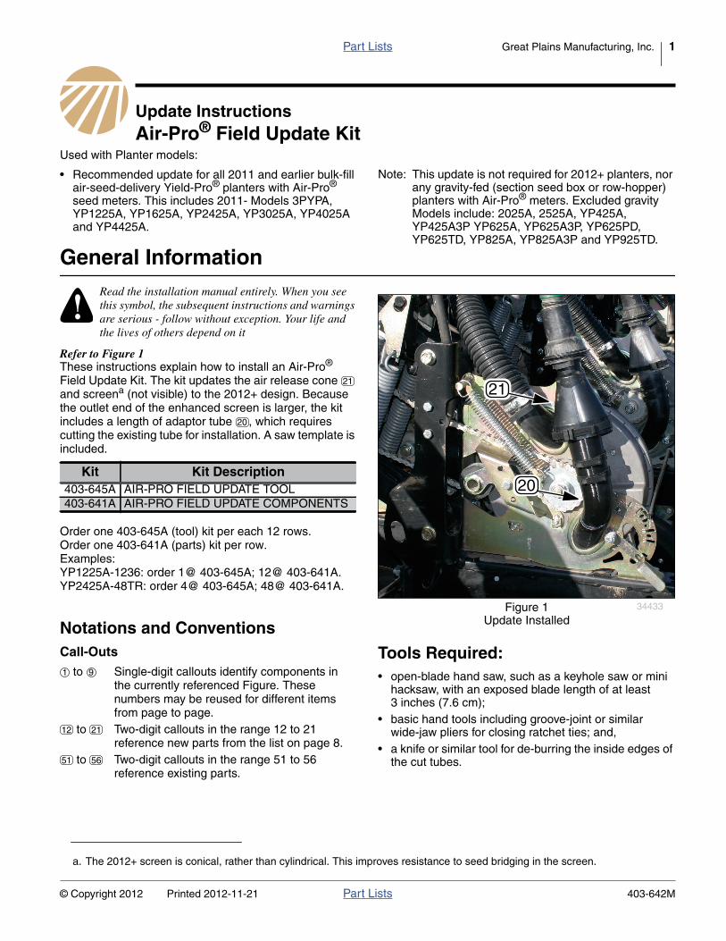
Refer to Figure 1These instructions explain how to install an Air-Pro®
Field Update Kit. The kit updates the air release coneand screena (not visible) to the 2012+ design. Becausethe outlet end of the enhanced screen is larger, the kitincludes a length of adaptor tube , which requirescutting the existing tube for installation. A saw template isincluded.
Order one 403-645A (tool) kit per each 12 rows.Order one 403-641A (parts) kit per row.Examples:YP1225A-1236: order 1@ 403-645A; 12@ 403-641A.YP2425A-48TR: order 4@ 403-645A; 48@ 403-641A.
Notations and ConventionsCall-Outs Tools Required:
• open-blade hand saw, such as a keyhole saw or minihacksaw, with an exposed blade length of at least3 inches (7.6 cm);
• basic hand tools including groove-joint or similarwide-jaw pliers for closing ratchet ties; and,
• a knife or similar tool for de-burring the inside edges ofthe cut tubes.
Read the installation manual entirely. When you seethis symbol, the subsequent instructions and warningsare serious - follow without exception. Your life andthe lives of others depend on it
a. The 2012+ screen is conical, rather than cylindrical. This improves resistance to seed bridging in the screen.
Kit Kit Description403-645A AIR-PRO FIELD UPDATE TOOL403-641A AIR-PRO FIELD UPDATE COMPONENTS
Note: This update is not required for 2012+ planters, norany gravity-fed (section seed box or row-hopper)planters with Air-Pro® meters. Excluded gravityModels include: 2025A, 2525A, YP425A,YP425A3P YP625A, YP625A3P, YP625PD,YP625TD, YP825A, YP825A3P and YP925TD.
Figure 1Update Installed
34433
20
2121
20
to Single-digit callouts identify components inthe currently referenced Figure. Thesenumbers may be reused for different itemsfrom page to page.
to Two-digit callouts in the range 12 to 21reference new parts from the list on page 8.
to Two-digit callouts in the range 51 to 56reference existing parts.
1 9
12 21
51 56
© Copyright 2012 Printed 2012-11-21 Part Lists 403-642M
2 Great Plains Manufacturing, Inc. Front Page Part Lists Air-Pro® Field Update Kit
Compatibility Check
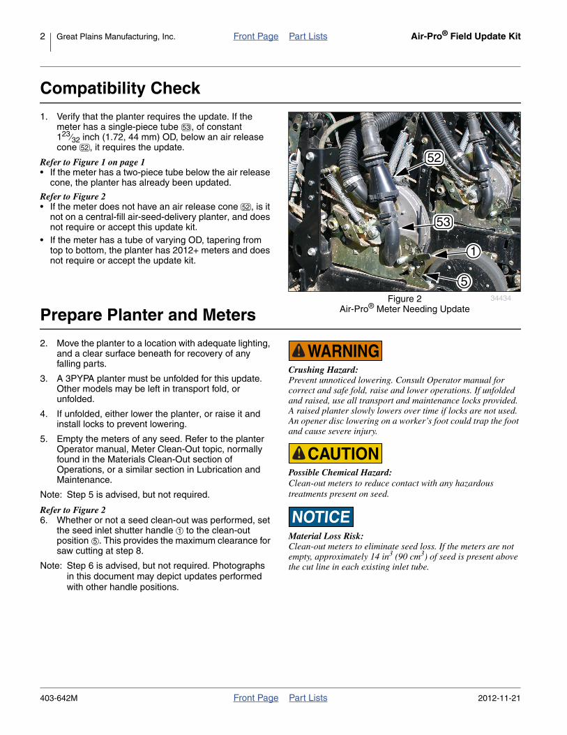
1. Verify that the planter requires the update. If themeter has a single-piece tube , of constant123⁄32 inch (1.72, 44 mm) OD, below an air releasecone , it requires the update.
Refer to Figure 1 on page 1• If the meter has a two-piece tube below the air release
cone, the planter has already been updated.
Refer to Figure 2• If the meter does not have an air release cone , is it
not on a central-fill air-seed-delivery planter, and doesnot require or accept this update kit.
• If the meter has a tube of varying OD, tapering fromtop to bottom, the planter has 2012+ meters and doesnot require or accept the update kit.
Prepare Planter and Meters
2. Move the planter to a location with adequate lighting,and a clear surface beneath for recovery of anyfalling parts.
3. A 3PYPA planter must be unfolded for this update.Other models may be left in transport fold, orunfolded.
4. If unfolded, either lower the planter, or raise it andinstall locks to prevent lowering.
5. Empty the meters of any seed. Refer to the planterOperator manual, Meter Clean-Out topic, normallyfound in the Materials Clean-Out section ofOperations, or a similar section in Lubrication andMaintenance.
Note: Step 5 is advised, but not required.
Refer to Figure 26. Whether or not a seed clean-out was performed, set
the seed inlet shutter handle to the clean-outposition . This provides the maximum clearance forsaw cutting at step 8.
Note: Step 6 is advised, but not required. Photographsin this document may depict updates performedwith other handle positions.
Figure 2Air-Pro® Meter Needing Update
34434
53
52
1
5
53
52
52
Crushing Hazard:Prevent unnoticed lowering. Consult Operator manual forcorrect and safe fold, raise and lower operations. If unfoldedand raised, use all transport and maintenance locks provided.A raised planter slowly lowers over time if locks are not used.An opener disc lowering on a worker’s foot could trap the footand cause severe injury.
Possible Chemical Hazard:Clean-out meters to reduce contact with any hazardoustreatments present on seed.
Material Loss Risk:Clean-out meters to eliminate seed loss. If the meters are notempty, approximately 14 in3 (90 cm3) of seed is present abovethe cut line in each existing inlet tube.
1
5
403-642M Front Page Part Lists 2012-11-21

Shorten Existing Inlet Tube Front Page Part Lists Great Plains Manufacturing, Inc. 3
Shorten Existing Inlet Tube
Install Cutting TemplateLeave the existing ratchet hose clamps in place torestrain the tube while cutting.
If the suggested quantity of 403-645A (tool) kits wasordered, you have one template for each 6 rows.
Refer to Figure 37. Select one new:
817-982C FIELD CUT TEMPLATE
Snap the template around the existing seed inlettube , with the larger angled beveled face towardand flush with the meter back plate.
Rework Risks:Make sure the template is flush with the meter backplate.Ensure that the cut follows the template (blade flush withtemplate, with template flush with meter and tube).
If the template is high, the cut tube will be too tall, and willneed to be re-cut to mate properly with the new tube extension.If the cut does not follow the template, parts of the tube edgewill be too tall, possibly creating an edge that can catch seed.
If the template is low, an air gap may be created, which cancause air metering problems, as well as create a gap that cancatch seed. This would require replacing and re-cutting the817-783C inlet tube.
Cut Existing Inlet TubeRefer to Figure 4, which depicts a mini hacksaw with apartially exposed open-ended blade8. Keeping the blade flat against the top guide
surface of the template, carefully cut the existingtube from front to back.
Equipment Damage Risk:Be particularly careful in the final 1⁄2 inches (2.5 cm) of cut.The blade is closer to the meter back plate than the drivechain . Reduce stroke length. Avoid striking the drive chainor the shutter index plate . Scratches will provide sites forrust to form.
Using a reciprocating saw(with a stroke length of over 1 inch:2.5 cm)for this cut is especially challenging - chain damage is likely.
Figure 3Cutting Template Affixed
34435
13
535151
53
13
13
53
Figure 4Cutting Existing Tube
34436
3
4
2
2
34
2012-11-21 Front Page Part Lists 403-642M
4 Great Plains Manufacturing, Inc. Front Page Part Lists Air-Pro® Field Update Kit
Remove Upper Cut Tube
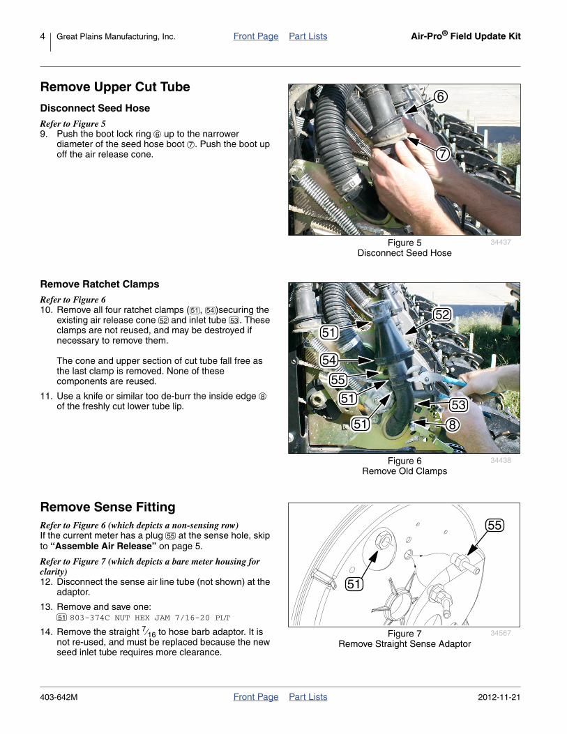
Disconnect Seed HoseRefer to Figure 59. Push the boot lock ring up to the narrower
diameter of the seed hose boot . Push the boot upoff the air release cone.
Remove Ratchet ClampsRefer to Figure 610. Remove all four ratchet clamps ( , )securing the
existing air release cone and inlet tube . Theseclamps are not reused, and may be destroyed ifnecessary to remove them.
The cone and upper section of cut tube fall free asthe last clamp is removed. None of thesecomponents are reused.
11. Use a knife or similar too de-burr the inside edgeof the freshly cut lower tube lip.
Remove Sense FittingRefer to Figure 6 (which depicts a non-sensing row)If the current meter has a plug at the sense hole, skipto “Assemble Air Release” on page 5.
Refer to Figure 7 (which depicts a bare meter housing forclarity)12. Disconnect the sense air line tube (not shown) at the
adaptor.
13. Remove and save one:803-374C NUT HEX JAM 7/16-20 PLT
14. Remove the straight 7⁄16 to hose barb adaptor. It isnot re-used, and must be replaced because the newseed inlet tube requires more clearance.
Figure 5Disconnect Seed Hose
34437
6
7
6
7
Figure 6Remove Old Clamps
34438
51
51
51
54
52
53
8
55
51 54
52 53
8
Figure 7Remove Straight Sense Adaptor
34567
55
51
55
51
403-642M Front Page Part Lists 2012-11-21
Install Update Front Page Part Lists Great Plains Manufacturing, Inc. 5
Install Update
Install Elbow Sense FittingRefer to Figure 6 (which depicts a non-sensing row)If the current meter has a plug at the sense hole, skipto “Assemble Air Release” on page 5.
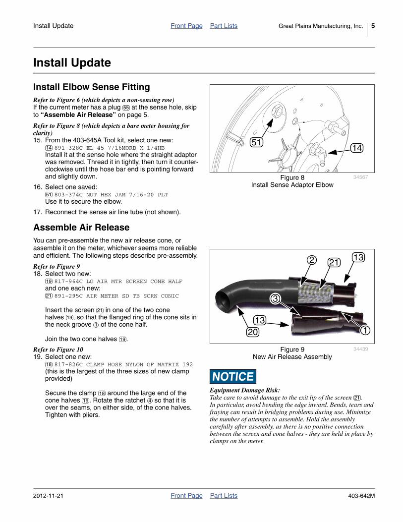
Refer to Figure 8 (which depicts a bare meter housing forclarity)15. From the 403-645A Tool kit, select one new:
891-328C EL 45 7/16MORB X 1/4HBInstall it at the sense hole where the straight adaptorwas removed. Thread it in tightly, then turn it counter-clockwise until the hose bar end is pointing forwardand slightly down.
16. Select one saved:803-374C NUT HEX JAM 7/16-20 PLT
Use it to secure the elbow.
17. Reconnect the sense air line tube (not shown).
Assemble Air ReleaseYou can pre-assemble the new air release cone, orassemble it on the meter, whichever seems more reliableand efficient. The following steps describe pre-assembly.
Refer to Figure 918. Select two new:
817-964C LG AIR MTR SCREEN CONE HALFand one each new:
891-295C AIR METER SD TB SCRN CONIC
Insert the screen in one of the two conehalves , so that the flanged ring of the cone sits inthe neck groove of the cone half.
Join the two cone halves .
Refer to Figure 1019. Select one new:
817-826C CLAMP HOSE NYLON GF MATRIX 192(this is the largest of the three sizes of new clampprovided)
Secure the clamp around the large end of thecone halves . Rotate the ratchet so that it isover the seams, on either side, of the cone halves.Tighten with pliers.
Figure 8Install Sense Adaptor Elbow
34567
1451
55
14
51
Equipment Damage Risk:Take care to avoid damage to the exit lip of the screen .In particular, avoid bending the edge inward. Bends, tears andfraying can result in bridging problems during use. Minimizethe number of attempts to assemble. Hold the assemblycarefully after assembly, as there is no positive connectionbetween the screen and cone halves - they are held in place byclamps on the meter.
Figure 9New Air Release Assembly
34439
21
1320
1321
1
2
3
19
21
21
19
1
19
18
18
19 4
2012-11-21 Front Page Part Lists 403-642M

6 Great Plains Manufacturing, Inc. Front Page Part Lists Air-Pro® Field Update Kit
Refer to Figure 920. Select one new:
817-981C FIELD FLARED SEED TUBE
Slide the larger end of the tube over the largerend of the screen , and up against the stops inthe cone half.
Install Air ReleaseRefer to Figure 1121. Being careful to hold the tube against the stops in
the cone halves , rotate the seed tube so that theelbow end is pointing away from the ratchetclamp .
Refer to Figure 1222. Being careful to hold the update tube against the
stops in the cone halves , place the elbow of theupdate tube over the shortened meter inlet tube .
Seat the new tube and cones in the existing saddleweldments of the meter.
Note: Do not use any sealant, glue or tape at the jointbetween the new and existing inlet tubes.
Note: With the meter rain cover removed, any seed diskremoved, and the shutter wide open, use a finger,from the disk side, to inspect the joint between thecut tube and the new update tube . Verifythat there are no ridges, gaps or cutting fray thatcould catch seed.
Figure 10Air Release Large Clamp
34441
1320
18
420
20 2
21 3
Figure 11Cone-Elbow Alignment
34441
1320
18
45
20
13
5
4
Figure 12Update Mounted
34442
53
5
13
20
20
13 5
53
53 20
403-642M Front Page Part Lists 2012-11-21

Install Update Front Page Part Lists Great Plains Manufacturing, Inc. 7
Refer to Figure 1323. Select two new:
800-434C NYLON HOSE CLAMP 2 1/8 - 2 3/8(these two clamps are the middle size of the threesizes provided)
Loosely secure these clamps , ratchets away frommeter, around the update tube and existing lowersaddle on the meter.
24. Select one new:800-016C UPPER FERT HOSE CLAMP RATCHET
(this is the smallest of the new clamps)
Loosely secure this clamp around the cone neckand existing upper saddle on the meter. Slide theclamp as far down on the saddle as possible, to allowthe seed hose boot to fully engage the cone neckflange.
25. Check that the update’s cone, screen and tubecomponents are still correctly aligned and fullyseated. Use pliers to tighten all clamp ratchets.
Reconnect Seed HoseRefer to Figure 1426. Make sure lock-ring is high on boot . Pull boot
fully over cone neck . Pull lock-ring down fully ontoboot.
Close-Out27. Re-position seed inlet shutters as desired.
28. Re-fold planter as desired.
Operation
No changes are required to normal planter operations.
Maintenance
If meter maintenance is required, be sure to use only theupdated parts for 2011- meters. Do not order pre-updateparts or 2012+ parts.
Figure 13Upper and Lower Clamps
34443
7
16
17
17
6
17
17
6
16
16
7
Figure 14Re-Connect Seed Hose
34444
8
19
9
9 8
13
2012-11-21 Front Page Part Lists 403-642M

8 Great Plains Manufacturing, Inc. Front Page Part Lists Air-Pro® Field Update Kit
Appendix
Part Lists
New PartsThe part call-out numbers in this list match all Figures inthese installation instructions. Part descriptions matchthose in your updated Parts Manual.
Quantities are units (“ea”).
403-645A AIR-PRO FIELD UPDATE TOOL
Order one
Kit Contents
403-645A AIR-PRO FIELD UPDATE COMPONENTS Kit Contents
Existing Parts
CalloutNumber
Quantityin Kit
PartNumber
PartDescription
11 - 403-645A AIR-PRO FIELD UPDATE TOOL
12 1 403-642M MANUAL FIELD UPTD KIT, AIR-PRO
13 2 817-982C FIELD CUT TEMPLATE
14 6 891-328C EL 45 7/16MORB X 1/4HB
CalloutNumber
Quantityin Kit
PartNumber
PartDescription
15 - 403-641A AIR-PRO FIELD UPDATE COMPONENTS
16 1 800-016C UPPER FERT HOSE CLAMP RATCHET
17 2 800-434C NYLON HOSE CLAMP 2 1/8 - 2 3/8
18 1 817-826C CLAMP HOSE NYLON GF MATRIX 192
19 2 817-964C LG AIR MTR SCREEN CONE HALF
20 1 817-981C FIELD FLARED SEED TUBE
21 1 891-295C AIR METER SD TB SCRN CONIC
CalloutNumber
PartNumber
PartDescription
PartDisposition
51 800-016C UPPER FERT HOSE CLAMP RATCHET Removed. Not re-used.51 803-374C NUT HEX JAM 7/16-20 PLT If present, removed and re-installed.52 817-773C AIR MTR SCREEN CONE HALF Removed. Not re-used.53 817-783C AIR MTR SEED INLET ELBOW Modified in place.54 817-826C CLAMP HOSE NYLON GF MATRIX 192 Removed. Not re-used.55 817-829C PLUG, FLUSH HEAD POLYETH 7/16 Left in place.56 890-979C SCREEN 20M 1.57 DIAX3.25 LONG Removed. Not re-used.57 891-122C AD 7/16MORB X 1/4HB If present, removed and replaced.
Great Plains Manufacturing, Inc.Corporate Office P.O. Box 5060
Salina, Kansas 67402-5060 USA
403-642M Front Page Part Lists 2012-11-21