Embed Size (px)
Citation preview

Fourth-Generation Mobile Communications MIMO High-speed Packet Transmission
Hidekazu Taoka
and Kenichi Higuchi
An ultra-high-speed packet transmission experiment for achieving a transmission
data rate of approximately 5 Gbit/s (spectral efficiency of 50 bit/s/Hz) was per-
formed using a 100-MHz channel bandwidth in broadband packet radio access. The
spectrum efficiency of 50 bit/s/Hz nearly approaches the upper limit in cellular envi-
ronments near a cell site taking into account inter-cell interference. We describe the
technology overview, experimental configuration, and field experimental results to
achieve the data rate of 5 Gbit/s.
1. IntroductionThe transmission data rate targeted by
Fourth-Generation mobile communication
systems called IMT-Advanced is 100
Mbit/s or greater in a cellular environment
having a wide coverage area with high-
mobility users and a maximum of 1 Gbit/s
or greater in an indoor or hot-spot area
with low-mobility users [1]. In previous
field experiments applying Variable
Spreading Factor (VSF)*1
-Spread Orthog-
onal Frequency Division Multiplexing
(OFDM)*2
radio access with a channel
bandwidth of 100 MHz, we achieved
ultra-high-speed packet transmission with
a throughput*3
of 1 Gbit/s (spectral effi-
ciency*4
of 10 bit/s/Hz). In these experi-
ments, we used Multiple-Input Multiple-
Output (MIMO) multiplexing consisting
of 4 transmitter/receiver antennas at dis-
tances up to 300 m from the base station
under mostly non-light-of-sight conditions
[2]. In Europe, the Wireless world INitia-
tive NEw Radio (WINNER)*5
research
forum has set the target value for peak
spectral efficiency in an isolated cell envi-
ronment to 25 bit/s/Hz as a system
requirement for next-generation mobile
communications [3]. In this regard, we
have also achieved an ultra-high-speed
packet transmission data rate of 2.5 Gbit/s
(spectral efficiency of 25 bit/s/Hz) in an
actual outdoor propagation environment
featuring mobile speeds of 5 to 20 km/h
through the use of 6 transmitter/receiver
antennas, 64Quadrature Amplitude Mod-
ulation (QAM)*6
, and turbo coding*7
with
a channel coding rate*8
of R = 8/9 [4].
In packet transmission, the maximum
transmission data rate typically corre-
sponds to peak throughput per cell. It is
therefore important that we investigate the
maximum achievable transmission data
rate since raising the maximum transmis-
sion data rate for one user results in
increasing the number of users that can be
accommodated by high-speed transmis-
sion. In a completely isolated cell envi-
ronment in which interference from
neighboring cells is nonexistent, the maxi-
mum transmission data rate can be raised
without limit by increasing the number of
transmitter/receiver antennas and raising
transmission power. In a multi-cell envi-
ronment, however, increasing the number
of transmitter/receiver antennas and rais-
ing transmission power serves to increase
the amount of interference from neighbor-
ing cells. The maximum achievable trans-
Field Experiment on 5-Gbit/s Ultra-high-speed Packet TransmissionUsing MIMO Multiplexing in Broadband Packet Radio Access
25NTT DoCoMo Technical Journal Vol. 9 No.2
*1 VSF: A technique that adaptively changes thespreading factor and channel coding rate in radiotransmission method that use data spreading such asW-CDMA and Spread OFDM (see *2). VSF pro-vides flexible support for various radio environments.
*2 Spread OFDM: OFDM is a digital modulationmethod that converts a high-data-rate signal intomultiple low-speed narrow-band signals and trans-mits them in parallel in the frequency domain toimprove resistance to multipath interference andachieve high spectral efficiency. Spread OFDM isa radio transmission method that transmits the
same signal using multiple subcarriers and timesymbols to increase received SINR (see *9) andsuppress thermal noise and inter-cell interference.
*3 Throughput: The amount of data transmittedwithout error per unit time, i.e., the effective datatransfer rate. In this article, throughout is defined asthe (data rate on the transmission side) × (numberof packets received without error per unit time) /(number of packets transmitted per unit time).
*4 Spectral efficiency: The number of data bits thatcan be transmitted per unit time per unit bandwidth.
*5 WINNER: A European research forum concerned
with radio transmission technology for next-gener-ation mobile communications. Founded in 2004.
*6 64QAM: A digital modulation method in wirelesscommunications that transmits data using 64 dif-ferent phase and amplitude constellations. Be ableto transmit 6 bits per symbol surpassing that of theQuadrature Phase Shift Keying (QPSK) and16QAM.
*7 Turbo coding: A type of error correction codingthat achieves powerful error-correction perfor-mance through iterative decoding using reliabilityinformation in decoded results.

26
Field Experiment on 5-Gbit/s Ultra-high-speed Packet Transmission Using MIMO Multiplexing in Broadband Packet Radio Access
NTT DoCoMo Technical Journal Vol. 9 No.2
*8 Channel coding rate: The ratio of the numberof data bits to the number of bits after error correc-tion coding (a coding rate of 8/9 means that 8 bitsof data become 9 bits after performing error cor-rection coding).
*9 Received SINR: Ratio of desired received signalpower to that of other received signals (interferingsignals from other cells or sectors and thermalnoise).
*10 VSF-Spread OFDM: A radio transmissionmethod proposed by NTT DoCoMo that appliesVSF to Spread OFDM. One of the candidates forincreasing system capacity in the downlink cellularenvironment and in hot-spot and indoor officeenvironments for next-generation mobile commu-nication systems.
*11 MLD: A method of signal separation in MIMOmultiplexing. Using the received signals of all thereceiver antenna branches, this method selects themost likely combination of signal points fromamong all possible signal-point candidates in the
digital modulation (64QAM in this article) of eachtransmitter antenna branch.
*12 ASESS: A method for sequentially selecting sym-bol replica candidates with high reliability based onthe reliability information and accumulated branchmetric of each symbol obtained by simple symbolranking using quadrant detection (see *19).
*13 Symbol replica candidate: Possible signal-point candidate of each transmitter antennabranch, and received signal-point candidate calcu-lated using estimated amount of fluctuation inchannel amplitude and phase.
mission data rate is therefore determined
by received Signal-to-Interference plus
Noise power Ratio (SINR)*9
that takes
inter-cell interference into account. We
simulated a 19-cell multi-cell environ-
ment (3 sectors/cell) with a base station
transmission power of 20W and distance
between base stations of 500 m with the
volume of traffic in neighboring cells
(channel load) as a parameter. Figure 1
shows the cumulative distribution func-
tion of received SINR obtained from this
simulation. These results show that the
distribution of received SINR improves as
channel load becomes smaller. But it can
also be seen that received SINR at nearly
all locations within a cell is no more than
approximately 30 dB even in the case of
small channel load. We can therefore con-
sider maximum received SINR in a cellular
environment to be approximately 30 dB
assuming a low channel load case. By per-
forming computer simulations under the
condition of a received SINR of 30 dB, we
found that a spectral efficiency of approxi-
mately 50 bit/s/Hz could be achieved.
In this article, we describe the technol-
ogy overview, experimental configuration,
and results of an ultra-high-speed packet
transmission field experiment using VSF-
Spread OFDM*10
radio access with a 100-
MHz channel bandwidth for achieving a
transmission data rate of approximately 5
Gbit/s (spectral efficiency of 50 bit/s/Hz),
which is practically the ultimate data rate
given inter-cell interference.
2. Technologies for 50-bit/s/Hz Ultra-high Spectral Efficiency
We applied the following technolo-
gies for achieving ultra-high spectral effi-
ciency of approximately 50 bit/s/Hz.
1) MIMO multiplexing with 12 trans-
mitter/receiver antennas
2) 64QAM and turbo coding with a
channel coding rate of R = 8/9
3) Signal separation algorithm based on
Maximum Likelihood Detection
(MLD)*11
The application of technologies 1) and
2) results in a transmission data rate of
4.915 Gbit/s (excluding the pilot signal and
other overhead) in OFDM radio access
with a channel bandwidth of 100 MHz.
The application of high-accuracy signal
separation technology 3) can significantly
decrease required received SINR compared
to other signal separation methods.
In this signal separation method, to
reduce the computational complexity of
MLD that is particularly high when using
higher data modulation, we applied Adap-
tive SElection of Surviving Symbol repli-
ca candidates (ASESS)*12
[5], a method
that we previously proposed using relia-
bility information of symbol replica can-
didates*13
, to complexity reduced MLD
with QR decomposition*14
and M-algo-
rithm*15
(QRM-MLD)*16
[6]. The QRM-
MLD method using ASESS can greatly
reduce computational complexity with
almost no deterioration in throughput.
This is achieved by decreasing the num-
ber of calculations of the Euclidean dis-
tance*17
required for signal separation by
using reliability information for each sym-
bol obtained simply by symbol*18
ranking
using quadrant detection*19
.
When achieving a transmission data
rate of 5 Gbit/s using radio transmission
technologies 1) to 3) above, QRM-MLD
with ASESS can reduce computational
complexity to approximately 1/(2×1017)
that of MLD incorporating no computa-
tion-reduction measures and to approxi-
mately 1/15 that of the original QRM-
MLD method.
3. Structure of MIMO Multiplexing Transceivers
Figure 2 shows the configuration of
the experimental transmitter and receiver
equipment that we constructed. Carrier
Cum
ulat
ive
dist
ribu
tion
fun
ctio
n (%
)
100
80
60
40
20
0–20 –10 0 10 20 30 40 50
Received SINR per receiver antenna (dB)
19 cells3 sectors/cellDistance between base stations: 500 m
Channel load100%75%50%30%20%10%
Figure 1 Cumulative distribution function of
received SINR in a cellular environment

27NTT DoCoMo Technical Journal Vol. 9 No.2
*14 QR decomposition: A mathematical techniquefor decomposing any m-row×n-column complexmatrix H into the product of m×n unitary matrixQ and n×n upper triangular matrix R (H=QR).
*15 M-algorithm: A method for successively reduc-ing symbol candidates at each stage (transmitterantenna) by selecting M (≤ N) of N symbol replicacandidates.
*16 QRM-MLD: As in MLD, this method selects themost likely combination of signal points fromamong all possible signal-point candidates of eachtransmit antenna branch. The application of QR
decomposition and M-algorithm significantlyreduces computational complexity.
*17 Euclidean distance: The shortest distancebetween two points in space.
*18 Symbol: In this article, the signal unit after errorcorrection coding and data modulation mapping.
*19 Quadrant detection: On the xy plane, a methodfor detecting which of four quadrants delimited bythe x and y axes centered on the origin an entity ispositioned in. Quadrant detection in this article iseasily performed by simply detecting the in-phaseand quadrature components of the received signal.
*20 Branch: In this article, an antenna and RF trans-mitter or receiver.
*21 IF: In a radio receiver circuit, specific frequenciesused for improving frequency selectivity andreceiver sensitivity. Although a variety of radiofrequencies are used in mobile communicationsystems, they are commonly converted to IFbefore demodulation within receiver circuits.
*22 Constraint length: Number of past input bitsneeded to obtain output. A longer constraintlength improves error correction performance butmakes for more computation in decoding.
frequency and bandwidth are 4.635 GHz
and 101.4 MHz, respectively. The trans-
mitter (the receiver) have 12 antennas and
each consist of a memory unit and radio
unit, the latter including a digital-to-analog
(D/A) (analog-to-digital (A/D)) converter.
In this experimental system, transmitted
signal generation before the D/A conver-
sion at the transmitter and received signal
demodulation after A/D conversion at the
receiver are done off-line by a worksta-
tion. However, because actual RF trans-
ceivers are used for the signal transmis-
sion, the transmission performance is the
same as for real-time signal transmission.
Table 1 shows the basic specifications of
the Radio Frequency (RF) unit and Table
2 the basic specifications of the baseband
signal processing unit.
In more detail, the transmitter consists
of a workstation equipped with a 480-
Gbyte hard disk, a memory unit with 9
Gbyte of memory per branch*20
, a 14-bit
D/A converter, Intermediate Frequency
(IF)*21
and RF transmission circuits, and
12 branches of transmitter antennas. First,
on the workstation, after the binary infor-
mation bit sequence is turbo coded (con-
straint length*22
= 4 bits; R = 8/9) and bit
interleaved*23
, the 64QAM data modula-
tion mapping is performed. It then per-
forms a serial-to-parallel conversion on
the transmit symbol sequence resulting
from data modulation, placing it onto
1,536 subcarriers. Next, the system time-
multiplexes quadrature pilot symbols*24
characteristic of the transmitter antennas
into subframes (subframe length: 0.5 ms)
and generates a symbol sequence for each
transmitter antenna. The symbol sequence
is converted to OFDM symbols (effective
symbol length: 15.170 µs) by a 2,048-
point Inverse Fast Fourier Transform
(IFFT)*25
and adds a Cyclic Prefix (CP)*26
with a duration of 2.067 µs. The baseband
modulated signal of the in-phase and
quadrature components*27
after CP inser-
tion is now stored in the memory unit of
the transmitter. A D/A conversion is per-
formed to the transmitted signals at a sam-
pling rate of 270 Msample/s followed by
quadrature modulation, conversion to a
RF signal, and transmission from each
antenna.
D/A
D/A
LPF
LPFBPFBPF
Quadraturemodulation
(a) Transmitter
Antenna 1
#12
Transmitterantennas
Transmitter RF unit
Transmitter amplifier Synthesizer Local
In-phaseQuadrature
In-phaseQuadrature
(Workstation)
Transmit basebandsignal generation
A/D
A/D
LPF
LPFAGCBPF Quadrature
detection
(b) Receiver
Antenna 1
#12
Receiver antennas
Receiver RF unit
LNASynthesizer Local
(Workstation)
Receiver basebandsignal decoding
Mem
ory
un
itM
emo
ry u
nit
BPF: Band Pass FilterLPF: Low Pass FilterLNA: Low Noise Amplifier
Figure 2 Configuration of MIMO transmitter/receiver experimental equipment

28 NTT DoCoMo Technical Journal Vol. 9 No.2
Field Experiment on 5-Gbit/s Ultra-high-speed Packet Transmission Using MIMO Multiplexing in Broadband Packet Radio Access
The receiver consists of 12 branches
of receiver antennas, RF and IF receiver
circuits, a 12-bit A/D converter, 18 Gbyte
of memory per branch, and a workstation
equipped with a 480-Gbyte hard disk. In
the IF band, the received signals are lin-
early amplified by an Automatic Gain
Control (AGC) amplifier, and then the
quadrature detection and A/D conversion
are performed. The baseband modulated
received signal of the in-phase and quad-
rature components is now stored in the
receiver’s large-capacity memory. Next,
at the workstation, the system takes this
digital signal and performs Fast Fourier
Transform (FFT)*28
window-timing*29
detection, and after performing CP
removal, it separates the signal into each
subcarrier’s components. Following this,
the channel estimation value*30
for each
subcarrier is measured by using two-
dimensional Minimum Mean Square
Error (MMSE) channel estimation*31
[7],
and in the signal-separation unit, signal
detection is performed by QRM-MLD
with ASESS using these channel estima-
tion values. Next, to perform soft-
decision*32
turbo decoding, we calculate a
Log Likelihood Ratio (LLR)*33
[8] for
each bit from the signal output from the
signal-separation unit, and after perform-
ing deinterleaving*23
, it inputs the signal
into a turbo decoder (Max-Log-MAP
decoding)*34
and recovers the transmit sig-
nal sequence.
4. Field Experimental ResultsThe field experiment was conducted
on the measurement course shown in
Figure 3 located in the Yokosuka
Research Park (YRP) district of Yokosu-
ka City, Kanagawa prefecture, Japan.
Photo 1 shows the base station antennas
and the measurement van equipped with
*23 Interleave: In this article, a technique for ran-domizing burst errors caused by fluctuation infading in mobile communications. Combininginterleaving with error correction coding raiseserror correction performance. Interleaving per-formed on a bit sequence before data modulationis called bit interleaving. Deinterleaving meansreturning the randomized transmit signal to itsoriginal order at the receiver.
*24 Pilot symbol: A symbol that is known to boththe transmitter and receiver. Used on the receiverside for symbol synchronization, for estimating
amplitude and phase fluctuation on the channel,and for estimating the received signal power, inter-ference power, and noise power.
*25 IFFT: The inverse transform of the FFT (see *28).Generates a temporal waveform signal by the con-volution of the signals of each frequency compo-nent.
*26 CP: A guard interval inserted between OFDMsymbols to eliminate inter-symbol interference andadjacent-subcarrier interference caused by multi-path delay.
*27 Baseband modulated signal of the in-phase
and quadrature components: In-phase andquadrature components of the digital signal beforequadrature modulation (after detection).
*28 FFT: A technique for quickly extracting the fre-quency components and their power ratios includ-ed in a signal.
*29 Window timing: Receive timing for performinga FFT.
*30 Channel estimation value: The estimatedamount of fluctuation in the propagation path(channel) using pilot symbols time-multiplexedwith data symbols within each packet frame.
Table 1 Basic specifications of RF unit
Carrier frequency
Bandwidth
No. of antennas
Base station transmission power
No. of quantized bits in D/A (A/D) converters
Sampling clock rate
Memory (per branch)
Hard disk capacity
4.635 GHz
101.4 MHz
12 (transmitter/receiver)
20 W (total)
14 bit (D/A)/12 bit (A/D)
270 Msample/s
9 Gbyte (Transmitter)/18 Gbyte (Receiver)
480 Gbyte
Table 2 Basic specifications of baseband signal processing unit
Radio access
Subframe length
No. of subcarriers
OFDM symbol duration
Spreading factor
Channel coding/decoding
Window timing detection
Channel estimation
Signal separation method
VSF-Spread OFDM
0.5 ms
1,536 (subcarrier separation: 65.919 kHz)
Data 15.170 μs + CP 2.067 μs
1
Turbo coding (R=8/9, K=4) /
Max-Log-MAP decoding
Pilot symbol-based window timing detection
Two-dimensional MMSE channel estimation filter
QRM-MLD with ASESS
Base station antenna
Hill
NTT DoCoMo R&D Center
Mobile station measurement course
300m
200m
100m
AB
Figure 3 Measurement course for field experiment
29NTT DoCoMo Technical Journal Vol. 9 No.2
mobile station antennas used in the field
experiment. The transmitter antenna at the
base station is a 12-branch sectored-beam
antenna*35
with a 3-dB width of 90
degrees in azimuth installed at a height of
approximately 26 m. The transmission
power and antenna gain of each antenna
were 20W and 19 dBi, respectively, and
antennas are linearly arranged with an
adjacent antenna separation of 70 cm
(equivalent to approximately 11 wave-
lengths for the carrier frequency of 4.635
GHz). The mobile station used 12 dipole
antennas*36
installed in a row at a height of
approximately 3.5 m. The antenna gain
was 2 dBi and the separation between
adjacent receiver antennas was set to 20
cm (equivalent to approximately 3.1
wavelengths). In the experiment, the mea-
surement van equipped with the mobile
station was driven along the measurement
course shown in Fig. 3 at an average
speed of approximately 10 km/h where
the distance from the transmitter was 150
to 200 m. The majority of the course is
under non-line-of-sight conditions due to
the surrounding office buildings that are
approximately three to six stories high
between the transmitter and receiver.
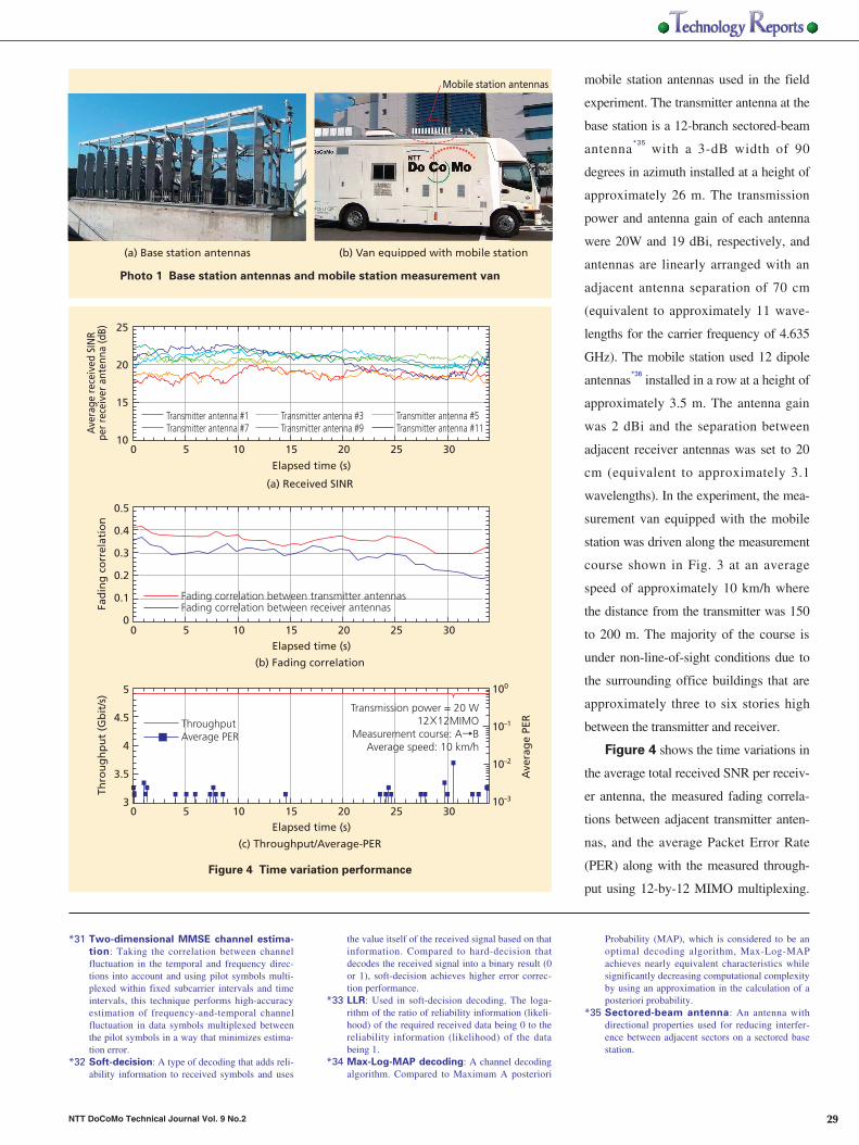
Figure 4 shows the time variations in
the average total received SNR per receiv-
er antenna, the measured fading correla-
tions between adjacent transmitter anten-
nas, and the average Packet Error Rate
(PER) along with the measured through-
put using 12-by-12 MIMO multiplexing.
*31 Two-dimensional MMSE channel estima-
tion: Taking the correlation between channelfluctuation in the temporal and frequency direc-tions into account and using pilot symbols multi-plexed within fixed subcarrier intervals and timeintervals, this technique performs high-accuracyestimation of frequency-and-temporal channelfluctuation in data symbols multiplexed betweenthe pilot symbols in a way that minimizes estima-tion error.
*32 Soft-decision: A type of decoding that adds reli-ability information to received symbols and uses
the value itself of the received signal based on thatinformation. Compared to hard-decision thatdecodes the received signal into a binary result (0or 1), soft-decision achieves higher error correc-tion performance.
*33 LLR: Used in soft-decision decoding. The loga-rithm of the ratio of reliability information (likeli-hood) of the required received data being 0 to thereliability information (likelihood) of the databeing 1.
*34 Max-Log-MAP decoding: A channel decodingalgorithm. Compared to Maximum A posteriori
Probability (MAP), which is considered to be anoptimal decoding algorithm, Max-Log-MAPachieves nearly equivalent characteristics whilesignificantly decreasing computational complexityby using an approximation in the calculation of aposteriori probability.
*35 Sectored-beam antenna: An antenna withdirectional properties used for reducing interfer-ence between adjacent sectors on a sectored basestation.
(a) Base station antennas (b) Van equipped with mobile station
Mobile station antennas
Photo 1 Base station antennas and mobile station measurement van
25
20
15
10
Ave
rag
e PE
R
100
10–1
10–2
10–3
Transmitter antenna #1Transmitter antenna #7
Transmitter antenna #3Transmitter antenna #9
Transmitter antenna #5Transmitter antenna #11
0 5 10 15 20 25 30
Elapsed time (s)
Elapsed time (s)
Elapsed time (s)
(a) Received SINR
Fad
ing
co
rrel
atio
n
0.5
0.4
0.3
0.2
0.1
0
Fading correlation between transmitter antennasFading correlation between receiver antennas
0 5 10 15 20 25 30
(b) Fading correlation
Thro
ug
hp
ut
(Gb
it/s
) 5
4.5
4
3.5
3
ThroughputAverage PER
0 5 10 15 20 25 30
(c) Throughput/Average-PER
Ave
rage
rec
eive
d SI
NR
per
rece
iver
ant
enna
(dB)
Transmission power = 20 W12×12MIMO
Measurement course: A→BAverage speed: 10 km/h
Figure 4 Time variation performance

Fig. 4(a) and (b) reveal that the received
SINR per transmitter antenna fluctuates in
the range of approximately 18 to 22 dB
and that the variation in the measured fad-
ing correlation over the course is small in
the range of approximately 0.2 to 0.4. Fig.
4(c) clearly shows that 4.915 Gbit/s pack-
et transmission with an average PER
below 10–2
is achieved at most of the loca-
tions along the measurement course where
the maximum distance from the base sta-
tion is approximately 200 m. Figure 5
shows the measured throughput using 12-
by-12 MIMO multiplexing as a function
of the average total received SINR with a
receiver antenna spacing of 20 cm. The
computer simulation results are also
shown assuming a propagation channel
condition corresponding to the average
value of delay spread*37
and fading correla-
tion between antennas along the measure-
ment course in the field experiment. From
the figure, we can see that the difference in
the required received SINR between the
results of the field experiment and those of
simulation is only within approximately 1
dB. This degradation is mainly due to the
difference in the propagation channel
model, channel estimation error, and sig-
nal detection error caused by the quantiza-
tion error in the A/D converter of the
implemented MIMO receiver. Fig. 5 also
shows that the peak throughput of 4.915
Gbit/s, i.e., the frequency efficiency of
approximately 50 bit/s/Hz, is achieved at
an average total received SINR per receiv-
er antenna of approximately 28.5 dB when
the receiver antenna spacing is 20 cm by
adopting the QRM-MLD signal detection
method with ASESS.
5. ConclusionWe described the technology behind
an ultra-high-speed packet transmission
field experiment using VSF-Spread
OFDM radio access for achieving a maxi-
mum transmission data rate of approxi-
mately 5 Gbit/s with a 100-MHz channel
bandwidth and presented field experimen-
tal results. Using MIMO multiplexing
consisting of 12 transmitter/receiver
antennas in an actual outdoor propagation
environment, we showed that ultra-high-
speed packet transmission with a maxi-
mum throughput of approximately 5
Gbit/s (spectral efficiency of approxi-
mately 50 bit/s/Hz) could be achieved
with a required average total received
SINR of approximately 28.5 dB.
References[1] ITU-R Recommendation M.1645.
[2] H. Taoka, K. Higuchi and M. Sawahashi:
“Field Experiments on Real-Time 1-Gbps
High-Speed Packet Transmission in MIMO-
OFDM Broadband Packet Radio Access,” in
Proc. IEEE VTC2006-Spring, Vol. 4, pp.
1812-1816, May 2006.
[3] IST-2003-507581, D7.1 v1.0, System
Requirements, WINNER, Jul. 2004.
[4] H. Taoka, K. Dai, K. Higuchi and M. Sawa-
hashi: “Field experiments on 2.5-Gbps pack-
et transmission using MLD-based signal
detection in MIMO-OFDM broadband pack-
et radio access,” in Proc. WPMC2006, Sep.
2006.
[5] K. Higuchi, H. Kawai, N. Maeda and M.
Sawahashi: “Adaptive Selection of Surviving
Symbol Replica Candidates Based on Maxi-
mum Reliability in QRM-MLD for OFCDM
MIMO Multiplexing,” in Proc. IEEE Globe-
com 2004, pp. 2480-2486, Nov. 2004.
[6] K. J. Kim and J. Yue: “Joint channel estima-
tion and data detection algorithms for
MIMO-OFDM systems,” in Proc. Thirty-Sixth
Asilomar Conference on Signals, Systems
and Computers, pp. 1857-1861, Nov.
2002.
[7] O. Edfors, M. Sandell, J.-J. Beek, S. Kate and
P. O. Borjesson: “OFDM channel estimation
by singular value decomposition,” IEEE
Trans. Commun., Vol. 46, No.7, pp. 931-
939, Jul. 1998.
[8] K. Higuchi, H. Kawai, N. Maeda, M. Sawa-
hashi, T. Itoh, Y. Kakura, A. Ushirokawa and
H. Seki: “Likelihood function for QRM-MLD
suitable for soft-decision turbo decoding
and its performance for OFCDM MIMO
multiplexing in multipath fading channel,”
in Proc. IEEE PIMRC 2004, pp. 1142-1148,
Sep. 2004.
30 NTT DoCoMo Technical Journal Vol. 9 No.2
*36 Dipole antenna: The simplest of all antennas,comprising two straight, linearly-aligned conduc-tor wires (elements) attached to the end of a cable(feed point).
*37 Delay spread: For radio propagation in mobilecommunications, the spread in delay time of allpaths (waves) arriving late because of reflection ordiffraction from buildings or other objects.Defined by a standard deviation determined byweighted statistical processing on delaytime of all
arriving paths (waves), using received signalpower.
Field Experiment on 5-Gbit/s Ultra-high-speed Packet Transmission Using MIMO Multiplexing in Broadband Packet Radio Access
Thro
ug
hp
ut
(Gb
it/s
)
5
4
3
2
1
024 25 26 27 28 29 30
Average total received SINR per receiver antenna (dB)
Field experimentSimulation
12×12MIMOMeasurement course: A→B
Average speed: 10 km/h
Figure 5 Throughput performance

31NTT DoCoMo Technical Journal Vol. 9 No.2
Hidekazu Taoka Assistant Manager, Radio Access Network Development Department
Joined in 2000. Engaged in the R&D of wireless accesstechnology for Fourth-Generation mobile communica-tion systems. A member of IEICE.
Kenichi HiguchiAssistant Manager, Radio Access Network Development Department
Joined in 1994. Engaged in the R&D of wireless accesstechnology for W-CDMA/Fourth-Generation mobilecommunication systems. Serving as both a lecturer in theFaculty of Science and Technology at the Tokyo Universi-ty of Science and as Assistant Manager in the RadioAccess Network Development Department since 2007.Ph. D., Engineering. A member of IEICE and IEEE.