Embed Size (px)
Citation preview
FIBERGLASS REINFORCED PLASTIC ASSETS - CORROSION
BARRIER CONDITION AND REMAINING SERVICE LIFE
Geoffrey E. Clarkson, P.Eng., ing., FEC UTComp Inc. Cambridge, Ontario, Canada [email protected] ABSTRACT Fiberglass reinforced plastic (FRP) is often used for bleaching applications in the pulp industry. It is commonly used for chlorine dioxide, sodium hypochlorite, filtrates and effluent applications. Design of this equipment employs an inner surface of the FRP called a corrosion barrier to protect the load-bearing structural elements of the asset from the fluids contained. Conventional practice is to monitor the condition of the corrosion barrier and assume that as long as the corrosion resistant layers are intact, no damage is occurring to the structural layers. This paper discusses several risk elements that affect FRP service life in addition to corrosion barrier surface oxidation. The paper then goes on to identify items to optimize maintenance and reliability of these FRP assets: assessment of the overall condition of the FRP, methods to inspect and evaluate while equipment is operating, corrosion barrier design and equipment design. INTRODUCTION Fiberglass Reinforced Plastic (FRP) is widely used for tanks, scrubbers, pipelines and other equipment in
the paper industry for corrosion resistance at moderate temperatures.
FRP is used in several applications in the pulp bleaching process, as well as for handling and storage of
other chemicals used throughout papermaking. Typical applications include carrying bleach filtrates,
filtrate tanks, chlorine dioxide handling, D-stage pre-tubes and stock lines.
FRP is known as a composite material because it is a mixture of several component materials. In addition, the material can be assembled in a number of different ways within the same structure or equipment to suit individual applications. This paper is written to provide insight into some damage mechanisms that occur with FRP and how reliability and Owner confidence can be increased through design and monitoring. Examples from experience will be presented for illustration. Some discussion of repairs for life extension will be provided. A PRIMER ON FRP It is generally understood that FRP is composed of 2 primary materials - resin and glass comprise more than 98% of most FRP. Each material plays an important role in the properties of the FRP. The roles of these constituent materials are outlined in Table 1.
Table 1
Constituent Details
Resin Most commonly discussed component of FRP
Functions as the “glue” that binds the structure and makes it leak-tight
Provides a significant portion of the corrosion and chemical resistance properties of FRP
Comprises 40% to 80% of a corrosion FRP structure
Provides 12% to 45% of the strength of the FRP
It is common to identify the FRP by the specific resin used
Glass Fiber Not commonly discussed in detail

Reinforcement Primary purpose is to provide structural strength in the direction of the glass fiber.
Allows FRP strength to be tailored for the loads by controlling orientations
Comprises 20% to 60% of a corrosion FRP structure
Provides 55% to 88% of the strength of the FRP
Occasionally, reinforcement of specific corrosion resistant layers might have a polyester reinforcement added, rather than glass. FRP is both a structural material and a corrosion resistant material. In the paper industry, FRP is used successfully for storage tanks, process vessels, washer hoods, tank linings and piping. Similar to stainless steel, FRP equipment provides corrosion resistance to the contents and environment while providing structural support for the stresses from containment. FRP construction for corrosion applications is illustrated in Figure 1. The photo shows how FRP is normally constructed for a corrosion application. The glass/resin fractions can be changed through the thickness and the glass fiber orientation can be modified to provide specific structural properties. In this Figure, the portion of the cross-section at the mold side (top), labelled “Corrosion Barrier”, is constructed to give more corrosion resistance by using a high fraction of resin and short strands of randomly oriented glass fibers. The innermost surface of this section is 90% resin and 10% reinforcement, using a thin reinforcement fabric. The section marked “Structural Layers” has higher glass fraction and examination of the photo will show that the glass fibers appear to be oriented. The outer layers at the bottom of the photo are made in a similar manner to the Corrosion Barrier and are placed for protection from the external environment. In some applications, the corrosion barrier is made using a thermoplastic sheet such as polyvinyl chloride (PVC), polypropylene (PP), various fluoropolymers and others. These generally offer superior corrosion resistance at a higher cost than FRP.
Figure 1

Figure 2 shows the appearance of a new corrosion barrier surface after all structural layers have been applied. Note that the structural layers are not visible below the inner surface. This is typical of many new constructions.
Figure 2
For design of FRP for corrosion applications, it can be specified that strength contributions from the corrosion barrier be removed from the calculations, so that only the structural portion is considered to support stresses from operating loads. This approach is almost identical to the use of “Corrosion Allowance” in ASME boiler and pipe calculations. When constructed, the corrosion barrier does contribute to the strength of the FRP. When FRP has been well constructed, separation between the corrosion barrier and the structural layers cannot be detected. As a further comparison, a safety factor of 10 is normally used to determine FRP allowable stresses, where a safety factor of 1.6 is used for many steel products. FRP FAILURE MODES IN THE PAPER INDUSTRY Many standards and codes have been developed and updated as a result of lessons learned from failures. Understanding failure modes allows continued evolution of design and inspection practices. At this time, it would be irresponsible to believe that all possible failure modes have been identified. Some failure modes are a direct result of manufacturing methods and practices in addition to flawed design or service conditions that were not adequately considered. This paper will discuss two types of failure modes: modes that progress gradually to loss of serviceability, and modes that can end in failure with loss of containment. Modes that lead to gradual loss of serviceability include:
Oxidation of corrosion barrier surfaces
Micro and small cracks in the corrosion barrier
Attack of the corrosion resistant layer resin by the substances contained
Process temperatures
Blisters and Diffusion
Modes that can lead to loss of containment failure include:
Attachment bond failure
Flange failure
Pipe support failure
Stress-corrosion cracking of glass fibers
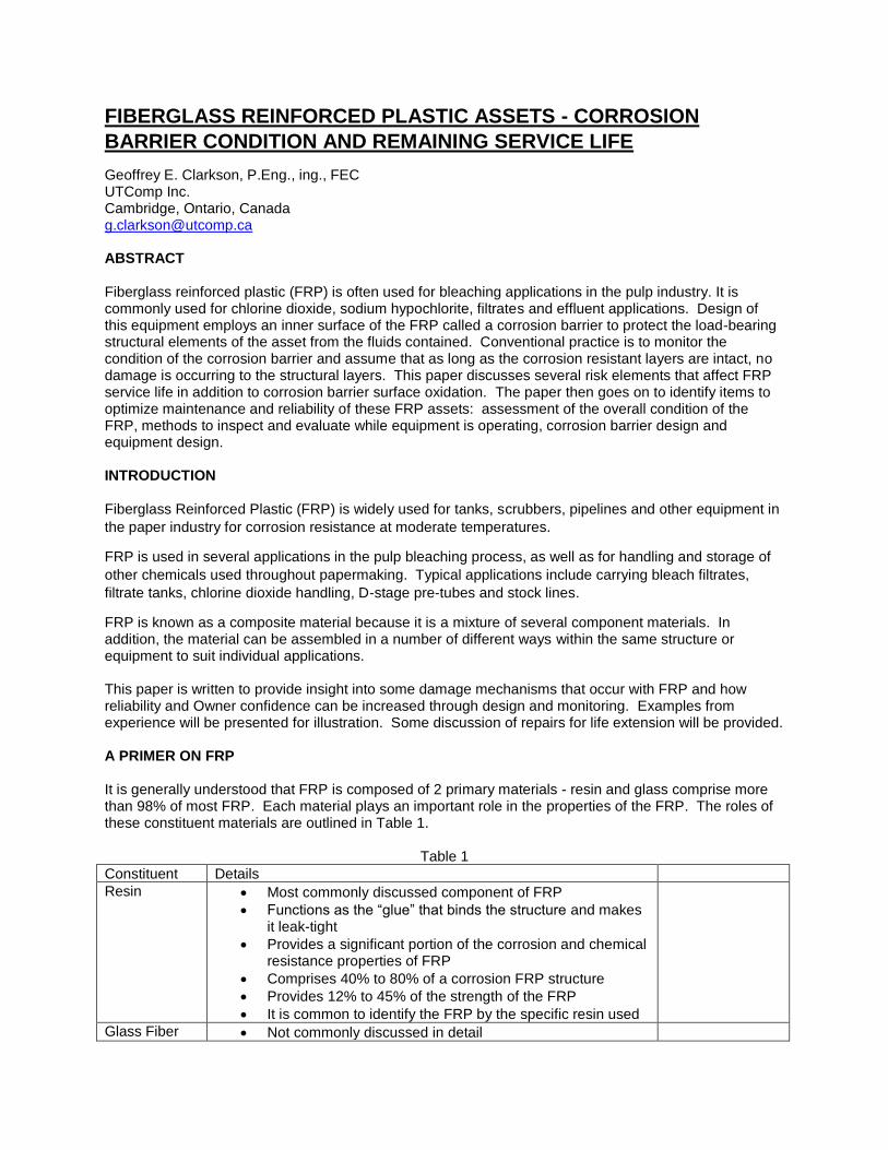
Impact damage Consider first the failure modes associated with gradual loss of serviceability. Note that the items listed are all related to the corrosion barrier and the process conditions. When following established design guidelines and standards, these modes are normally expected to occur. The primary purpose of the corrosion barrier is to protect the structural layers from the substances contained, primarily using the resin. We will briefly discuss the modes: Oxidation of corrosion barrier surfaces: The resins used in FRP are all organic polymers, and therefore they can be oxidized. When oxidizing agents such as sodium hypochlorite (hypo), chlorine and chlorine dioxide are contained, oxidation of the resin will occur. This oxidation shows as direct loss of resin from the corrosion barrier. Where organic (polyester) veils are used, they will also be oxidized. When these substances are contained, an FRP corrosion barrier must be considered to be sacrificial. An example of extensive oxidation is shown in Figure 3. In general, glass fibers will not be oxidized and when released they may become tramp material in the process. If fluid is moving along the surface, such as in a stock line or upflow tube, the oxidized resin is often abraded off. This is normally found in any equipment that handles chlorine dioxide and hypo.
Figure 3
Oxidation is quite easy to detect visually. In Figure 3, the resin in the surface has been yellowed by exposure to chlorine dioxide and loss of material is evident. The oxidized resin on the surface is softened and can be abraded off with little effort. Oxidation reduces the thickness of the corrosion barrier. In cases where oxidation occurs, the total thickness of the FRP will reduce. Micro and small cracks in the corrosion barrier: This mode is often cited but is difficult to detect until the cracks are fairly large – more than 40 microns wide – or they have been stained by the process fluid. The most common cause of this failure appears to be mechanical in origin. The origin appears to be from stresses created from differences between the coefficient of thermal expansion of resin and glass, combined with the reality that the resin experiences

more rapid changes than the structural glass. These cracks originate in the exposed resin-rich surface and progress into the laminate until they are stopped by increased restraint from reinforcement or imperfect bonding at exotherm interfaces. The chemical cause of these cracks include where resin curing is incomplete and there are free ester linkages are attacked by alkali to make soaps, and failure of the corrosion barrier reinforcement fibers from attack by process fluids. Further discussion of this mode follows under process temperatures and stress-corrosion cracking of glass fibers. Attack of the corrosion resistant layer resin by the substances contained: In this discussion, this is differentiated from oxidation in that the resin surface will appear to be intact, although some changes will be detected. The changes will appear as changes in the glossiness of the resin surface, changes in the hardness of the surface and changes in the colour (but not darkening). These changes occur as a result of chemical reactions taking place within some areas of the resin as a result of aggressive chemical reactions. Chemicals that are known to cause these changes include sodium hydroxide (caustic), hypo, solvents and some acids. Figure 4 shows an example of the inner surface of a chemical storage tank. All components shown were made using the same materials at about the same time. The different surface textures and colours reflect surface attack.
Figure 4

Process temperatures: As mentioned above, the thermal expansion of resins and glass differ markedly. For this reason, process temperatures can cause significant changes in expansion. In the corrosion barrier, with a higher resin fraction than the structural layers, the difference can create cracks. When formed, these cracks allow process fluid to gain access deeper into the laminate and can form into inter-layer cracks that may result in separation. An example is shown in Figure 5 which is the inner surface of a scrubber. Note how sections of the corrosion barrier have actually come off of the vessel. Failure of the surface of the corrosion barrier has allowed the process fluids direct access to structural reinforcement.
Figure 5
Blistering and Diffusion Blisters are formed in some corrosion barriers as a result of two (2) main mechanisms – heating and diffusion. Blisters are caused by heating when local areas separate from underlying areas because of thermal expansion. This can result in permanent deformation. In many cases, process fluids will diffuse though the blister skin and collect in the cavity underneath. Blisters caused by diffusion result when process fluids diffuse into the corrosion barrier and collect in a local area where resin is weakly bonded to underlying areas. It is important to note that diffusion of process fluids into FRP occurs, whether blisters form or not. As an example, consider Figure 6 which shows an electron micrograph which has been surveyed using energy dispersive x-ray (EDX). The FRP is a specimen removed from a tank that contains hydrochloric acid (HCL). No blisters have been observed in the corrosion barrier, but chlorine concentration has been detected to the full depth of 3.4mm shown. Diffusion is common and it should be expected to occur in all corrosion barriers A third mechanism for blistered appearance has been noted where the separation has occurred within the structural layers. This cannot generally be identified using visual methods. An example is shown in Figure 7. In the cases identified, the diameter has been 2000mm or greater where the inner surface appeared to be blistered, but the structural laminate appears to be separating as shown. This is termed as “Structural Blistering”.

Image courtesy of Owens Corning
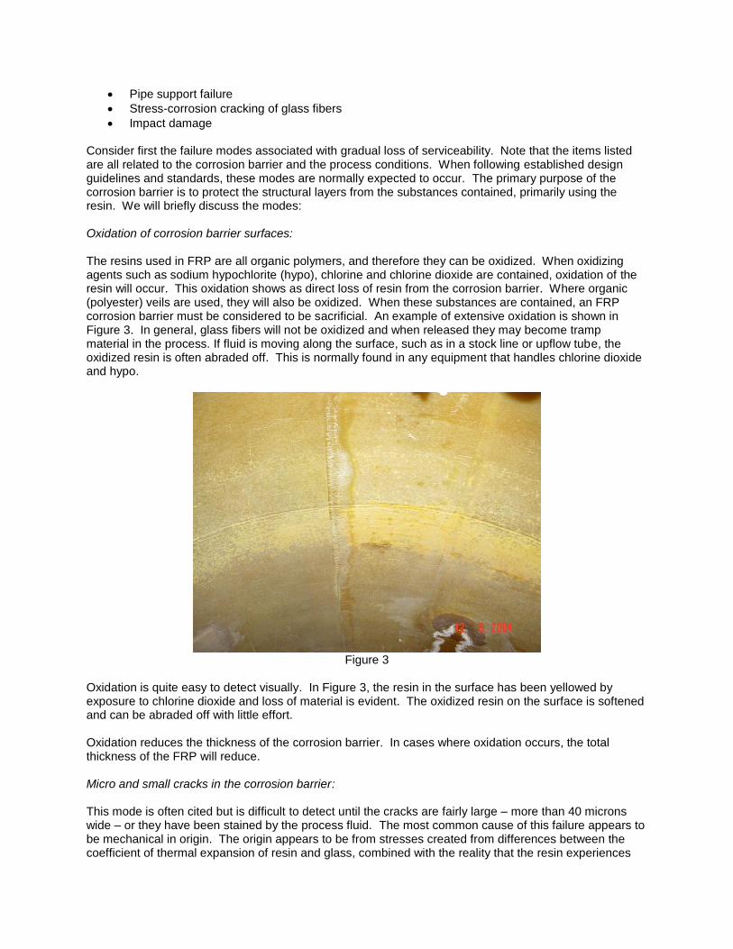
Figure 6 All of the modes discussed above usually produce gradual changes in an FRP asset that can be monitored over time. Now consider the modes that are associated with failure of the FRP structure. Many design standards and codes include compensation for some of these items. If the items below are fully considered in the design and manufacture, then the gradual modes described above will dominate, resulting in changes that can be monitored over time. We will briefly discuss the modes: Attachment bond failure: Attachments to FRP pipe and tanks, especially nozzles, are bonded to the parent structure. The bonds are known as “Secondary Bonds” because the resin in the parent structure is already cured and the crosslinking available for the new resin is negligible. The forces applied to these bonds resolve as two (2) distinct components – shear and peel. If the bonding practice follows accepted norms and the shear length of the bond is adequate, shear failures are rare. Peel describes forces that are normal to the bonded surface. These occur commonly with nozzles and stub-ins, where internal pressure applies a “peeling force” to the attachment where the attachment surfaces are normal to the loads. The peel resistance of a bond is low compared to its shear resistance. Peel failures are relatively common. When peel failures occur, there is usually loss of containment. Figure 7 shows a nozzle after peel failure that emptied a tank.
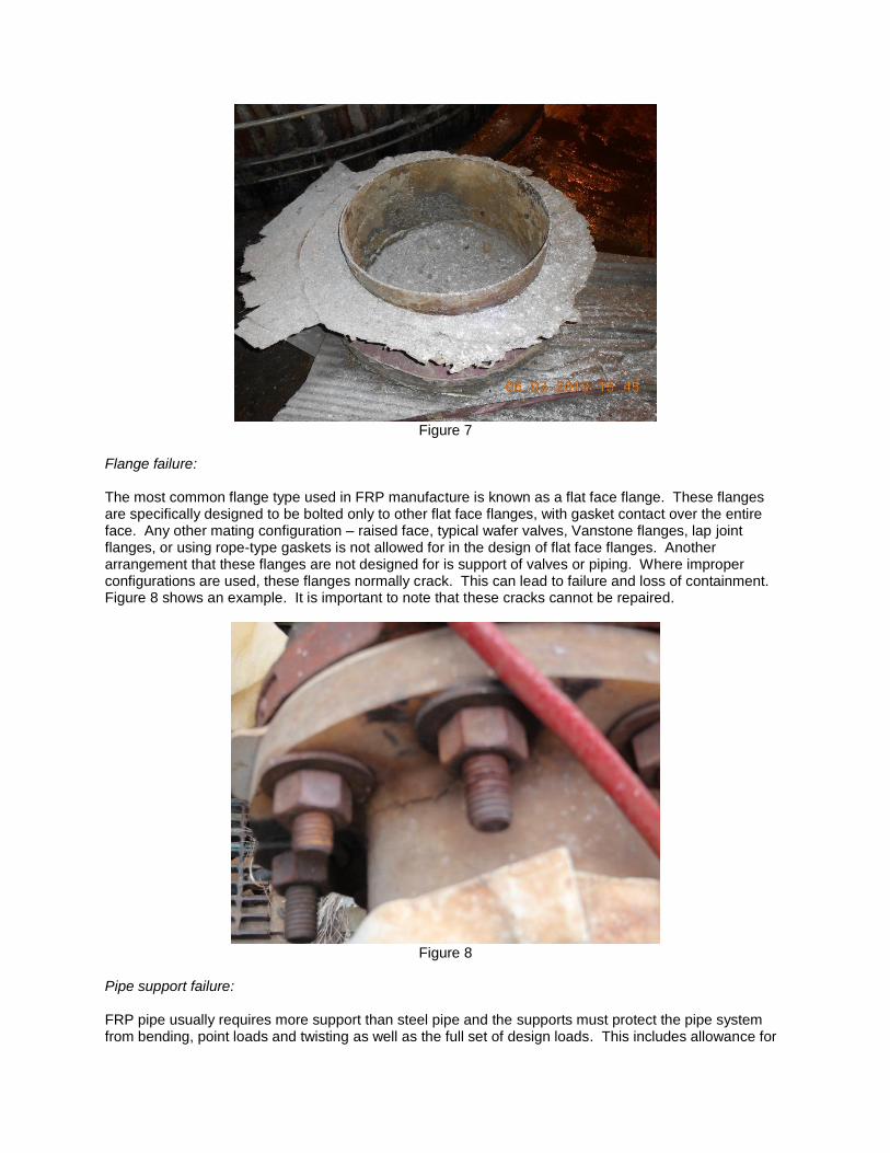
Figure 7
Flange failure: The most common flange type used in FRP manufacture is known as a flat face flange. These flanges are specifically designed to be bolted only to other flat face flanges, with gasket contact over the entire face. Any other mating configuration – raised face, typical wafer valves, Vanstone flanges, lap joint flanges, or using rope-type gaskets is not allowed for in the design of flat face flanges. Another arrangement that these flanges are not designed for is support of valves or piping. Where improper configurations are used, these flanges normally crack. This can lead to failure and loss of containment. Figure 8 shows an example. It is important to note that these cracks cannot be repaired.
Figure 8
Pipe support failure: FRP pipe usually requires more support than steel pipe and the supports must protect the pipe system from bending, point loads and twisting as well as the full set of design loads. This includes allowance for
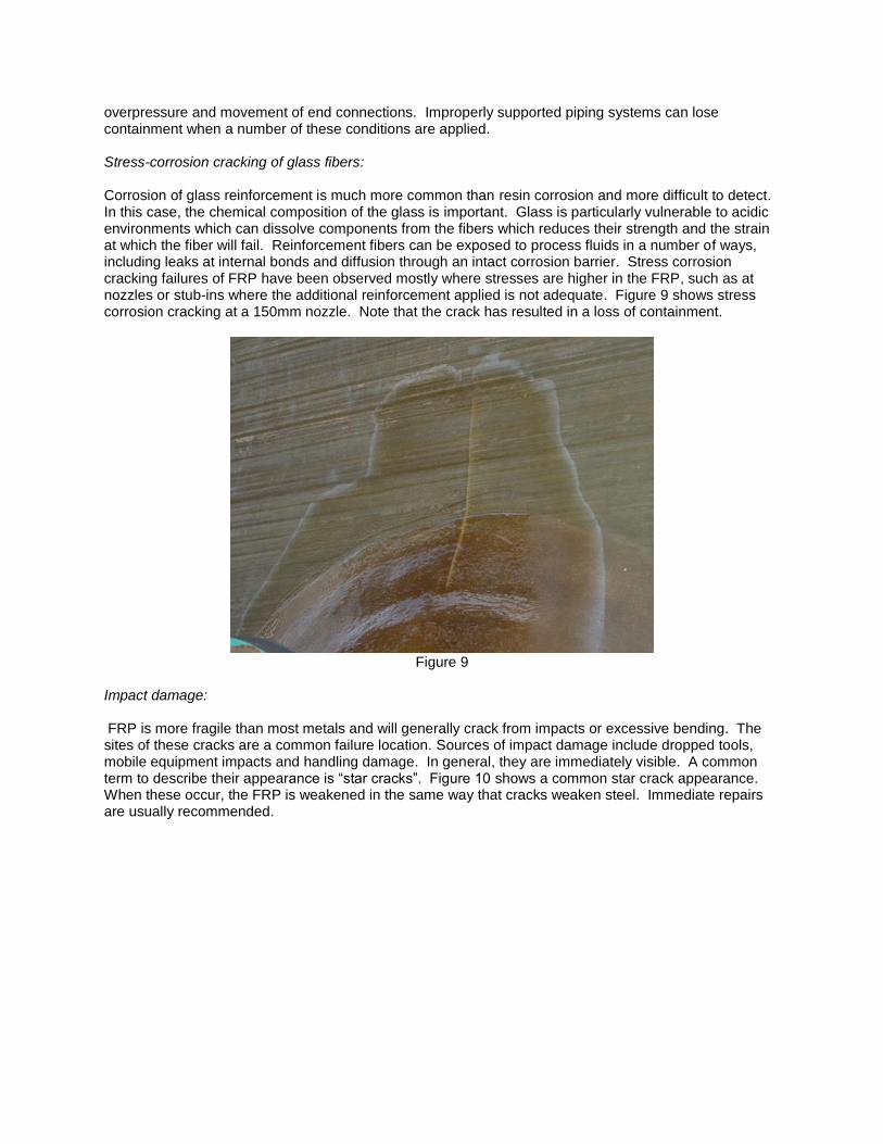
overpressure and movement of end connections. Improperly supported piping systems can lose containment when a number of these conditions are applied. Stress-corrosion cracking of glass fibers: Corrosion of glass reinforcement is much more common than resin corrosion and more difficult to detect. In this case, the chemical composition of the glass is important. Glass is particularly vulnerable to acidic environments which can dissolve components from the fibers which reduces their strength and the strain at which the fiber will fail. Reinforcement fibers can be exposed to process fluids in a number of ways, including leaks at internal bonds and diffusion through an intact corrosion barrier. Stress corrosion cracking failures of FRP have been observed mostly where stresses are higher in the FRP, such as at nozzles or stub-ins where the additional reinforcement applied is not adequate. Figure 9 shows stress corrosion cracking at a 150mm nozzle. Note that the crack has resulted in a loss of containment.
Figure 9
Impact damage: FRP is more fragile than most metals and will generally crack from impacts or excessive bending. The sites of these cracks are a common failure location. Sources of impact damage include dropped tools, mobile equipment impacts and handling damage. In general, they are immediately visible. A common term to describe their appearance is “star cracks”. Figure 10 shows a common star crack appearance. When these occur, the FRP is weakened in the same way that cracks weaken steel. Immediate repairs are usually recommended.

Figure 10
DESIGN AND MONITORING FOR RELIABILITY IMPROVEMENT The paper industry has seen evolution toward improved planning and reliability. Repairs of assets are inevitable so having processes in place that provide good information on asset condition and repair needs are necessary for cost effective facility operation. Some of the costs and opportunities are listed in Table 1.
Table 1
What is the VALUE? What are the COSTS?
Knowing prior to a shutdown what is needed Replacing or repairing prematurely with limited scope control
Baseline information on new equipment Not inspecting for compliance with specifications Repeatability and reproducibility Limited or subjective knowledge about assets Being able manage within budget cycle Emergency repairs or failures Having data collected outside of asset with an external visual inspection
Risk for confined space entry
Of getting valuable information WHILE in operation Internal inspection (clean out, shutdown time, lost income)
Being able to monitor existing equipment for changes over time
Not knowing when a repair or replacement is needed
Good safety record – personnel and equipment Risk of environmental clean up Good relations with community Public relations due to a spill or accident Being able to run operations to maximum efficiency and with limited down time
Lost opportunity
There is a large amount of attention given to corrosion barrier design and inspection. The structural layers that form the backbone of the containment system are usually hidden from view, making inspection difficult. As discussed above, the modes that result in loss of containment are all related to the structural layers. Corrosion Barriers There is a large amount of published literature and standards on appropriate design and construction of FRP corrosion barriers. In addition, the manufacturers of resins and glass also provide

recommendations based on experience and independent research following recognized standards. These resources can be called upon to produce reliable corrosion barrier designs. Regardless of the original corrosion barrier design, FRP corrosion barriers are not immune to the modes of failure discussed above. Some corrosion barrier designs might slow the rate of change, but no design has been found by this writer that eliminates the changes. Because the changes occur, monitoring and inspection of the corrosion barrier is required to understand its condition and trigger corrective action when required. The conventional inspection and monitoring approach for corrosion barriers requires access to the surface so that the surface can be assessed based on its appearance, surface hardness and the depth of attack based on divot tests as described in TAPPI standard practice 0402
1.. In general, these methods
allow reasonable evaluation of oxidation, some micro-cracking, process temperature damage and surface attack. When damage to accessible surface is detected, it has probably also occurred to the surfaces that are not accessible, such as small nozzles. When the corrosion barrier surface is not accessible, such as for pipe and vessels in operation, alternative methods can be used. For small diameter pipe, some success has been achieved using digital x-ray to determine the thickness of the corrosion barrier. Another method, known as the UTComp® System, takes ultrasonic readings which in addition to thickness and finding internal defects, can determine the hardness of the corrosion barrier surface, the current effectiveness of the corrosion barrier and the structural capacity of the entire FRP thickness. The ultrasonic method mentioned above allows evaluation of oxidation, oxidation depth, some data related to diffusion depth, process temperature damage and surface damage. The effects of microcracking on the surface also appear to be discernable when the corrosion barrier is submerged. Conventional repairs to extend the life of corrosion barriers consist of partial removal of the damaged corrosion barrier and replacement with a new corrosion barrier on the accessible surfaces. From the discussion above, there are several items to note:
The original barrier must be removed sufficiently to prevent diffusion products (such as chlorine) from affecting the new lining or from forming tear-gas-like vapour in the workspace,
The new lining must use materials that continue the protect the structure,
The new lining must be fully cured – heated post-curing is recommended in all cases,
Replacement of nozzles smaller than 200mm should be considered using penetrating design as shown in applicable standards,
All new seal bonds must be fully bonded and cured to prevent leakage along the bond,
Consider what is required to ensure that small nozzles and inaccessible surfaces will not limit the life extension.
Following this conventional practice can increase the lifetime of the corrosion barrier but there is no guarantee that it will address any of the modes associated with failures of the structural layers. Structural Layers Some of the failure modes identified can be seen from external inspection. In those cases, it is important to identify the problem and take appropriate repair action. The most important part of monitoring in these cases is to identify the potential for the failure modes to develop and to take appropriate preventive action. For items such as pipe supports, flanges and impact damage visual examination is the only proven method of detection. Where risk elements are identified, such as incorrect supports, incorrect valves or risk of impact from traffic the appropriate actions are preventive. Items such as structural blistering, attachment bond failure and stress corrosion cracking can be monitored using non-destructive ultrasonic methods developed by UTComp®. These methods identify when the modes are developing and are able to calculate remaining service life.

Some further design features that will help to control failure modes include:
Use penetrating-type installation for all nozzles smaller than 200mm,
Use boron-free glass fibers (Owens Corning Advantex or ECR) for all reinforcements,
Ensure that design calculations considered peel appropriately at all large nozzles,
Ensure that all seal bond lengths are at least 75mm long and at least as thick as the corrosion barrier.
Maintenance for Reliability Before any FRP equipment is accepted, it should be inspected for conformance to good design and manufacturing practice, including the items above, by a competent inspector. Throughout the service life of the FRP, use regular inspections and evaluations to monitor the condition of FRP. The inspections should include:
External visual evaluation focused on identifying possible failure modes,
Non-destructive structural evaluations (such as the UTComp® System) to monitor inner surface condition and structural condition,
Internal inspections where required. When repairs are required, they should be designed or specified by a competent FRP engineer and inspected when complete. Repairs to the corrosion barrier should take advantage of the opportunity to address the structural design features listed above. To accelerate repair completion, heated post-curing of the resin should be expected. REMAINING SERVICE LIFE DETERMINATION For this paper, the Remaining Service Life (RSL) is defined as:
The time from the date of inspection to when the structural capacity of the equipment is adequate to perform its operational requirements with a safety factor of 2.
To ensure clarity, the safety factor is designed as:
This definition provides some buffer to allow equipment to be removed from service, hopefully while preventing loss of containment. This definition allows consideration of the full thickness of the FRP in the equipment, including the available corrosion barrier thickness. The approach used is to primarily consider the structural capacity of the primary sections such as shells and reinforcements where modes such as SCC, attachment failure or support failure historically appear. The structural capacity is determined from ultrasonic readings taken from the asset and processed using proprietary methods. The method also considers changes that occur as a result of repairs such as relining. These calculations are used to project the RSL, and can be presented in graphical form as in Figure 11. Figure 11 shows actual results for an FRP tank. Changes in strength of the shell are shown in the period from 1996 to 2011. Repairs with structural reinforcement were completed in 2011 and the increased structural capacity of the tank is shown by the increase in the 2012 inspection. The drop from 2012 to 2013 is the result of incomplete corrosion barrier cure. In the chart, Percentage of Design Strength is the current percentage of the original design strength of the FRP. The Design Strength of the FRP is obtained from calculation or destructive tests of the new, fully cured laminate. Normally, FRP is designed with a safety factor of 10, which is used as100% on the chart. As a result, a safety factor of 2 corresponds to 20%. The red lines show the levels at which RSL is calculated.

Figure 11
This methodology has been shown to work for FRP used in tanks, ducts, scrubbers, pipe and structural
elements such as beams.
References
1. TAPPI, “Best practice for inspecting used fiber-reinforced plastics (FRP) equipment”, Designation TIP 0402, 2007.
2. Clarkson, Geoff P.Eng., ing. FEC, “Suitability for Service Using the UTComp® System, R4”, UTComp Monograph, 2014.
3. American Petroleum Institute, “Tank Inspection, Repair, Alteration, and Reconstruction”, Designation API 653, Fourth Edition, 2009.
4. European Committee for Standardization, “GRP tanks and vessels for use above ground – Part 3: Design and workmanship”, Designation EN 13121-3:2008+A1, 2010.
5. American Society of Mechanical Engineers, "Reinforced Thermoset Plastic Corrosion-Resistant Equipment", Designation RTP-1.
0%
20%
40%
60%
80%
100%
120%
1996 1998 2000 2002 2004 2006 2008 2010 2012 2014
Pe
rce
nat
age
of
De
sign
Str
en
gth
Year