Embed Size (px)
Citation preview
™
Fiber Optics User Guide by Nick BlasCablesonDemand.com Technology Editor
™
Amphenol Single Mode 9/125 fiber optic patch cords feature a 9 micron core and 125 micron cladding. This narrow core diameter prevents heavy signal losses due to attenuation. Pre-cision ceramic ferules provide a flawless interface between the cable and connecting device. Laser optimized for 1310nm light sources with an insertion loss ≤0.30dB and a return loss ≥55dB.
Amphenol Multi-Mode 50/125 fiber optic patch cords feature a 50 micron core and 125 micron cladding. 50/125 MM fiber is actually an older type of fiber optic cabling that is making a significant comeback within the industry. This is because its 50 micron core supports greater bandwidth. 50/125 MM is com-patible with legacy 850nm LED light sources or legacy 1300mm laser light sources with an insertion loss ≤0.30dB. This cable type is intended only for legacy systems that specify its usage.
Amphenol Multi-Mode 62.5/125 fiber optic patch cords feature a 62.5 micron core with 125 micron cladding. This is the most popular MM fiber optic cable type in use today due to its affordability and flexibility. Most Local Area Networks utilize 62.5 micron fiber with 850nm LED based light sources for short runs up to 550m in length. This cable can be recognized by its slightly thicker orange colored jacket. The thicker core makes field repairs and splicing a much easier task. Insertion loss is ≤0.30dB.
Amphenol 10 Gigabit Multi-Mode 50/125 fiber optic patch cords utilize special 50 micron cores that are specifically opti-mized for new laser based 10 Gigabit Ethernet signals. The special glass cores permit data transfer at 5X the rate of stan-dard 50/125 MM cables. 10 Gig rated cables are easily identi-fied by their aqua colored jackets. Our 10 Gig 50/125 cables are reverse compatible with existing 50/125 systems as well. We recommend these Laser Optimized Multi-Mode Fiber (LOMMF) cables as the backbone of any network installation where extremely high bandwidths are required. Insertion loss is ≤0.30dB.
FC Connector
The FC, or Fixed Connection, fiber optic connector is one of the more popular choices for Single Mode fiber applications. FC interconnects have also made their way onto various testing and diagnostic systems. This is a threaded con-nector with an alignment key, so please ensure that the keyway is aligned properly before tightening. Failure to do so could result in unwanted signal loss.
LC Connector
The LC, or Lucent Connector, is a fiber optic termination with a small form factor. It utilizes a reduced diameter 1.25mm ferrule, which is approximately half the size of its cousin, the ST connector. Performance characteristics are excellent and subsequently the LC connector is favored for Single Mode applications. This is one of the newer connector styles in use today.
MU Connector
The MU fiber optic connector is a small form factor version of the SC connec-tor. It maintains the SC’s robust push-pull mating mechanism for a secure fit. Due to the MU’s reduced size, it can fit two channels in the same footprint as a single channel SC termination. This connector is extremely popular in Japan.
SC Connector
The SC, or Subscriber Connector, is a general purpose Push/Pull style con-nector that is properly keyed to support send/receive channels. The SC houses a 2.5mm ferrule within an over-molded housing for added protection against damage. SC connectors provide solid performance for both Single and Multi-Mode applications.
ST Connector
The ST, or Straight Tip, fiber optic connector is a quick-release bayonet style termination developed by AT&T. ST’s are predominately found on legacy installations from the late 80’s and early 90’s, but they have been known to migrate onto newer platforms as well. The ST features a 2.5mm ferrule in a keyed package. They are spring loaded and require proper seating to mini-mize loss.
MT-RJ Connector
The MT-RJ, or Mechanical Transfer-Registered Jack, fiber optic connector was designed to replace the much larger SC connector. It is popular due to its low profile, which is similar in size to a telephone plug. It snaps in place with ease much like an RJ-45 networking termination. The MT-RJ utilizes a rectangular ferrule rather than a round one like its predecessor.
Amphenol Mode Conditioning fiber optic cables are used primarily in Gigabit Ethernet based networks where both Single-Mode and Multi-Mode interconnects must be main-tained. Mode conditioning cables prevent an anomaly known as Differential Mode Delay, or DMD. When an unconditioned laser source designed for operation on SM fiber cable is directly coupled to an MM fiber cable, differential mode delay (DMD) can occur. DMD can degrade the modal bandwidth of the fiber-optic cable, causing a decrease in the link span (the distance between the transmitter and the receiver) that is reliably supported.
Amphenol Loopback fiber optic cables are designed to provide a simple method of testing transmit and receive ports on an optical switch. We carry both Single Mode and Multi-Mode variants to fit you particular application.
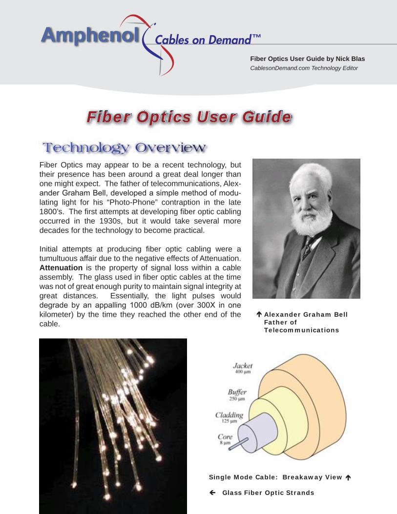
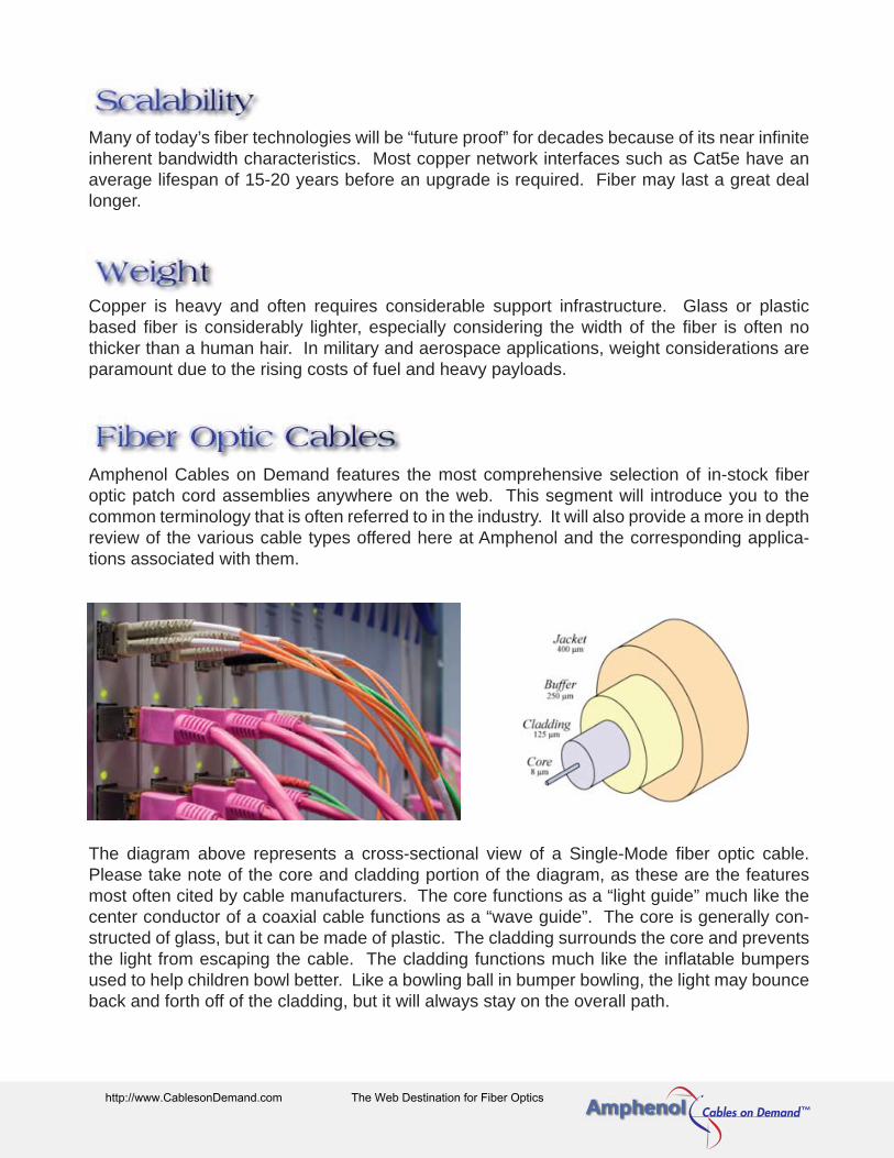
Single Mode Cable: Breakaway View Glass Fiber Optic Strands
Alexander Graham BellFather of Telecommunications
Block Diagram: Electro-Optical Conversion
Image of a Fiber Optic Media Converter
Advantages of Fiber OpticsAdvantages of Fiber Optics
Fiber Optic ShowcaseFiber Optic Showcase
Fiber Optic ConnectorsFiber Optic Connectors
Diagram: Single Mode vs. Multi-Mode Fiber
Multi-Mode Fiber Single Mode Fiber
Cable TV Infrastructure Telephone Infrastructure Metropolitan Area Networks
Small Office Complexes Educational Departments New Residential Complexes
Fiber Optics may appear to be a recent technology, but their presence has been around a great deal longer than one might expect. The father of telecommunications, Alex-ander Graham Bell, developed a simple method of modu-lating light for his “Photo-Phone” contraption in the late 1800’s. The first attempts at developing fiber optic cabling occurred in the 1930s, but it would take several more decades for the technology to become practical.
Initial attempts at producing fiber optic cabling were a tumultuous affair due to the negative effects of Attenuation. Attenuation is the property of signal loss within a cable assembly. The glass used in fiber optic cables at the time was not of great enough purity to maintain signal integrity at great distances. Essentially, the light pulses would degrade by an appalling 1000 dB/km (over 300X in one kilometer) by the time they reached the other end of the cable.
In the late 1960’s, Corning patented and refined the process of making the fiber optic cores out of glass, thereby bringing the attenuation rate down to 20 dB/km or less. This is one of many features that make fiber optics so attractive. Unlike Copper twisted pair cabling like Cat5e or Cat6, which is limited to 100m lengths, fiber runs often exceed 50 miles in length!
Nearly every electronic gadget today operates in the “Digital Domain”. The Digital Domain is a term describing the use of digital signals in the circuitry of a particular device or its corre-sponding infrastructure. Digital signals can be supported throughout multiple mediums. The only pre-requisite being digital communication must be achieved in a binary fashion of some type (1’s and 0’s). In the case of a digital signal operating over a fiber optic link, a light source pulsing on would represent a value of 1 and a light source pulsing off would represent a value of 0. In the case of a digital signal operating over a Copper link, an electrical pulse would be used instead of light. Devices such as Fiber Optic Media Converters allow data to be exchanged between Copper-based and optical-based systems. The ability to easily convert between a Copper based network and a Fiber based network is critical because each technol-ogy has its own inherent advantages and disadvantages.
Some of the primary benefits of using a fiber optic based network infrastructure include:
Light by its nature is far more resilient than electricity when it comes to traveling long distances. One needs only to gaze into the night sky to see the light that emanates from sources trillions of miles away elsewhere in the universe. Fiber optics operate under a similar principle. A powerful light source such as a laser coupled with a precision crafted fiber optic cable assembly can drive a signal for several miles without the need for a booster.
The theoretical bandwidth limitations of fiber optics are nearly infinite. In fact, present day fiber optic cable technologies are theoretically capable of supporting bandwidths that exceed the capabilities of even the most advanced network devices. Estimates suggest almost 85-90% of the United States’ fiber optic infrastructure is un-used because the bandwidth capability is so vast.
10 Gigabit per second data rates are easily supported by the latest generation of fiber optic interconnects. 10 Gigabit data rates over copper are far more difficult to maintain, especially over extended distances. In September of 2006, the Nippon Telegraph and Telephone Corpo-ration laid claim to the speed throne with a 14 terabits per second transmission over a single 100-mile fiber optic line.
Fiber optic links are completely invulnerable to electromagnetic interference. Copper links require shielding to protect against EMI/RFI, but even the most intensely shielded systems can still fall victim to major sources of interference. This is why the military often relies on fiber optics for their most critical systems.
Maintenance costs are low for fiber optic installations over the long run. Copper has a tendency to oxidize and corrode over time, eventually requiring replacement. The pure glass construction of fiber optic cables does not suffer from this particular problem.
Many of today’s fiber technologies will be “future proof” for decades because of its near infinite inherent bandwidth characteristics. Most copper network interfaces such as Cat5e have an average lifespan of 15-20 years before an upgrade is required. Fiber may last a great deal longer.
Copper is heavy and often requires considerable support infrastructure. Glass or plastic based fiber is considerably lighter, especially considering the width of the fiber is often no thicker than a human hair. In military and aerospace applications, weight considerations are paramount due to the rising costs of fuel and heavy payloads.
Amphenol Cables on Demand features the most comprehensive selection of in-stock fiber optic patch cord assemblies anywhere on the web. This segment will introduce you to the common terminology that is often referred to in the industry. It will also provide a more in depth review of the various cable types offered here at Amphenol and the corresponding applica-tions associated with them.
The diagram above represents a cross-sectional view of a Single-Mode fiber optic cable. Please take note of the core and cladding portion of the diagram, as these are the features most often cited by cable manufacturers. The core functions as a “light guide” much like the center conductor of a coaxial cable functions as a “wave guide”. The core is generally con-structed of glass, but it can be made of plastic. The cladding surrounds the core and prevents the light from escaping the cable. The cladding functions much like the inflatable bumpers used to help children bowl better. Like a bowling ball in bumper bowling, the light may bounce back and forth off of the cladding, but it will always stay on the overall path.
There are two main categories of fiber optic cables: Single Mode (abbreviated SM) and Multi-Mode (abbreviated MM).
Single Mode fiber features an extremely narrow core diameter. The light path is so narrow that it only supports a single mode or wavelength of light transmission (a single ray of light). Since the light path is so narrow, there is no room for light pulses to overlap and distort. This reduces signal attenuation and supports extremely long distance installations. Single Mode fiber is almost always signified by its yellow colored jacket.
Multi-Mode fiber features a much wider core diameter, thus allowing the light pulses to travel down multiple modes or paths down the cable. MM fiber tends to cost less than SM fiber since the thicker cores are easier to terminate. MM fiber is preferred for short to medium distances. Therefore, most premise installations utilize MM fiber, which is often signified by its orange colored jacket.
Common Single Mode fiber applications include long distance telephone infrastructure, cable TV infrastructure, Metropolitan Area Networks (MAN), or any application where cable lengths exceed 550m in length or 10 Gb/s in bandwidth.
LAN Applications for 62.5/125 fiber include any type of premise installation where space is limited. Enterprise applications are commonplace such as small office complexes. Educa-tional departments on college campuses and newer residential complexes also may use this type of cable.
Fiber Optics User GuideFiber Optics User Guide

Amphenol Single Mode 9/125 fiber optic patch cords feature a 9 micron core and 125 micron cladding. This narrow core diameter prevents heavy signal losses due to attenuation. Pre-cision ceramic ferules provide a flawless interface between the cable and connecting device. Laser optimized for 1310nm light sources with an insertion loss ≤0.30dB and a return loss ≥55dB.
Amphenol Multi-Mode 50/125 fiber optic patch cords feature a 50 micron core and 125 micron cladding. 50/125 MM fiber is actually an older type of fiber optic cabling that is making a significant comeback within the industry. This is because its 50 micron core supports greater bandwidth. 50/125 MM is com-patible with legacy 850nm LED light sources or legacy 1300mm laser light sources with an insertion loss ≤0.30dB. This cable type is intended only for legacy systems that specify its usage.
Amphenol Multi-Mode 62.5/125 fiber optic patch cords feature a 62.5 micron core with 125 micron cladding. This is the most popular MM fiber optic cable type in use today due to its affordability and flexibility. Most Local Area Networks utilize 62.5 micron fiber with 850nm LED based light sources for short runs up to 550m in length. This cable can be recognized by its slightly thicker orange colored jacket. The thicker core makes field repairs and splicing a much easier task. Insertion loss is ≤0.30dB.
Amphenol 10 Gigabit Multi-Mode 50/125 fiber optic patch cords utilize special 50 micron cores that are specifically opti-mized for new laser based 10 Gigabit Ethernet signals. The special glass cores permit data transfer at 5X the rate of stan-dard 50/125 MM cables. 10 Gig rated cables are easily identi-fied by their aqua colored jackets. Our 10 Gig 50/125 cables are reverse compatible with existing 50/125 systems as well. We recommend these Laser Optimized Multi-Mode Fiber (LOMMF) cables as the backbone of any network installation where extremely high bandwidths are required. Insertion loss is ≤0.30dB.
FC Connector
The FC, or Fixed Connection, fiber optic connector is one of the more popular choices for Single Mode fiber applications. FC interconnects have also made their way onto various testing and diagnostic systems. This is a threaded con-nector with an alignment key, so please ensure that the keyway is aligned properly before tightening. Failure to do so could result in unwanted signal loss.
LC Connector
The LC, or Lucent Connector, is a fiber optic termination with a small form factor. It utilizes a reduced diameter 1.25mm ferrule, which is approximately half the size of its cousin, the ST connector. Performance characteristics are excellent and subsequently the LC connector is favored for Single Mode applications. This is one of the newer connector styles in use today.
MU Connector
The MU fiber optic connector is a small form factor version of the SC connec-tor. It maintains the SC’s robust push-pull mating mechanism for a secure fit. Due to the MU’s reduced size, it can fit two channels in the same footprint as a single channel SC termination. This connector is extremely popular in Japan.
SC Connector
The SC, or Subscriber Connector, is a general purpose Push/Pull style con-nector that is properly keyed to support send/receive channels. The SC houses a 2.5mm ferrule within an over-molded housing for added protection against damage. SC connectors provide solid performance for both Single and Multi-Mode applications.
ST Connector
The ST, or Straight Tip, fiber optic connector is a quick-release bayonet style termination developed by AT&T. ST’s are predominately found on legacy installations from the late 80’s and early 90’s, but they have been known to migrate onto newer platforms as well. The ST features a 2.5mm ferrule in a keyed package. They are spring loaded and require proper seating to mini-mize loss.
MT-RJ Connector
The MT-RJ, or Mechanical Transfer-Registered Jack, fiber optic connector was designed to replace the much larger SC connector. It is popular due to its low profile, which is similar in size to a telephone plug. It snaps in place with ease much like an RJ-45 networking termination. The MT-RJ utilizes a rectangular ferrule rather than a round one like its predecessor.
Amphenol Mode Conditioning fiber optic cables are used primarily in Gigabit Ethernet based networks where both Single-Mode and Multi-Mode interconnects must be main-tained. Mode conditioning cables prevent an anomaly known as Differential Mode Delay, or DMD. When an unconditioned laser source designed for operation on SM fiber cable is directly coupled to an MM fiber cable, differential mode delay (DMD) can occur. DMD can degrade the modal bandwidth of the fiber-optic cable, causing a decrease in the link span (the distance between the transmitter and the receiver) that is reliably supported.
Amphenol Loopback fiber optic cables are designed to provide a simple method of testing transmit and receive ports on an optical switch. We carry both Single Mode and Multi-Mode variants to fit you particular application.
Single Mode Cable: Breakaway View Glass Fiber Optic Strands
Alexander Graham BellFather of Telecommunications
Block Diagram: Electro-Optical Conversion
Image of a Fiber Optic Media Converter
Advantages of Fiber OpticsAdvantages of Fiber Optics
Fiber Optic ShowcaseFiber Optic Showcase
Fiber Optic ConnectorsFiber Optic Connectors
Diagram: Single Mode vs. Multi-Mode Fiber
Multi-Mode Fiber Single Mode Fiber
Cable TV Infrastructure Telephone Infrastructure Metropolitan Area Networks
Small Office Complexes Educational Departments New Residential Complexes
Fiber Optics may appear to be a recent technology, but their presence has been around a great deal longer than one might expect. The father of telecommunications, Alex-ander Graham Bell, developed a simple method of modu-lating light for his “Photo-Phone” contraption in the late 1800’s. The first attempts at developing fiber optic cabling occurred in the 1930s, but it would take several more decades for the technology to become practical.
Initial attempts at producing fiber optic cabling were a tumultuous affair due to the negative effects of Attenuation. Attenuation is the property of signal loss within a cable assembly. The glass used in fiber optic cables at the time was not of great enough purity to maintain signal integrity at great distances. Essentially, the light pulses would degrade by an appalling 1000 dB/km (over 300X in one kilometer) by the time they reached the other end of the cable.
In the late 1960’s, Corning patented and refined the process of making the fiber optic cores out of glass, thereby bringing the attenuation rate down to 20 dB/km or less. This is one of many features that make fiber optics so attractive. Unlike Copper twisted pair cabling like Cat5e or Cat6, which is limited to 100m lengths, fiber runs often exceed 50 miles in length!
Nearly every electronic gadget today operates in the “Digital Domain”. The Digital Domain is a term describing the use of digital signals in the circuitry of a particular device or its corre-sponding infrastructure. Digital signals can be supported throughout multiple mediums. The only pre-requisite being digital communication must be achieved in a binary fashion of some type (1’s and 0’s). In the case of a digital signal operating over a fiber optic link, a light source pulsing on would represent a value of 1 and a light source pulsing off would represent a value of 0. In the case of a digital signal operating over a Copper link, an electrical pulse would be used instead of light. Devices such as Fiber Optic Media Converters allow data to be exchanged between Copper-based and optical-based systems. The ability to easily convert between a Copper based network and a Fiber based network is critical because each technol-ogy has its own inherent advantages and disadvantages.
Some of the primary benefits of using a fiber optic based network infrastructure include:
Light by its nature is far more resilient than electricity when it comes to traveling long distances. One needs only to gaze into the night sky to see the light that emanates from sources trillions of miles away elsewhere in the universe. Fiber optics operate under a similar principle. A powerful light source such as a laser coupled with a precision crafted fiber optic cable assembly can drive a signal for several miles without the need for a booster.
The theoretical bandwidth limitations of fiber optics are nearly infinite. In fact, present day fiber optic cable technologies are theoretically capable of supporting bandwidths that exceed the capabilities of even the most advanced network devices. Estimates suggest almost 85-90% of the United States’ fiber optic infrastructure is un-used because the bandwidth capability is so vast.
10 Gigabit per second data rates are easily supported by the latest generation of fiber optic interconnects. 10 Gigabit data rates over copper are far more difficult to maintain, especially over extended distances. In September of 2006, the Nippon Telegraph and Telephone Corpo-ration laid claim to the speed throne with a 14 terabits per second transmission over a single 100-mile fiber optic line.
Fiber optic links are completely invulnerable to electromagnetic interference. Copper links require shielding to protect against EMI/RFI, but even the most intensely shielded systems can still fall victim to major sources of interference. This is why the military often relies on fiber optics for their most critical systems.
Maintenance costs are low for fiber optic installations over the long run. Copper has a tendency to oxidize and corrode over time, eventually requiring replacement. The pure glass construction of fiber optic cables does not suffer from this particular problem.
Many of today’s fiber technologies will be “future proof” for decades because of its near infinite inherent bandwidth characteristics. Most copper network interfaces such as Cat5e have an average lifespan of 15-20 years before an upgrade is required. Fiber may last a great deal longer.
Copper is heavy and often requires considerable support infrastructure. Glass or plastic based fiber is considerably lighter, especially considering the width of the fiber is often no thicker than a human hair. In military and aerospace applications, weight considerations are paramount due to the rising costs of fuel and heavy payloads.
Amphenol Cables on Demand features the most comprehensive selection of in-stock fiber optic patch cord assemblies anywhere on the web. This segment will introduce you to the common terminology that is often referred to in the industry. It will also provide a more in depth review of the various cable types offered here at Amphenol and the corresponding applica-tions associated with them.
The diagram above represents a cross-sectional view of a Single-Mode fiber optic cable. Please take note of the core and cladding portion of the diagram, as these are the features most often cited by cable manufacturers. The core functions as a “light guide” much like the center conductor of a coaxial cable functions as a “wave guide”. The core is generally con-structed of glass, but it can be made of plastic. The cladding surrounds the core and prevents the light from escaping the cable. The cladding functions much like the inflatable bumpers used to help children bowl better. Like a bowling ball in bumper bowling, the light may bounce back and forth off of the cladding, but it will always stay on the overall path.
There are two main categories of fiber optic cables: Single Mode (abbreviated SM) and Multi-Mode (abbreviated MM).
Single Mode fiber features an extremely narrow core diameter. The light path is so narrow that it only supports a single mode or wavelength of light transmission (a single ray of light). Since the light path is so narrow, there is no room for light pulses to overlap and distort. This reduces signal attenuation and supports extremely long distance installations. Single Mode fiber is almost always signified by its yellow colored jacket.
Multi-Mode fiber features a much wider core diameter, thus allowing the light pulses to travel down multiple modes or paths down the cable. MM fiber tends to cost less than SM fiber since the thicker cores are easier to terminate. MM fiber is preferred for short to medium distances. Therefore, most premise installations utilize MM fiber, which is often signified by its orange colored jacket.
Common Single Mode fiber applications include long distance telephone infrastructure, cable TV infrastructure, Metropolitan Area Networks (MAN), or any application where cable lengths exceed 550m in length or 10 Gb/s in bandwidth.
LAN Applications for 62.5/125 fiber include any type of premise installation where space is limited. Enterprise applications are commonplace such as small office complexes. Educa-tional departments on college campuses and newer residential complexes also may use this type of cable.
Fiber Optics User GuideFiber Optics User Guide
Fiber Optics User Guide by Nick BlasCablesonDemand.com Technology Editor
™
™http://www.CablesonDemand.com The Web Destination for Fiber Optics
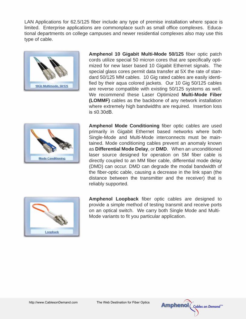
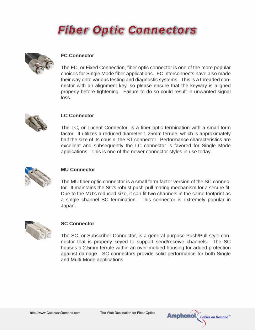
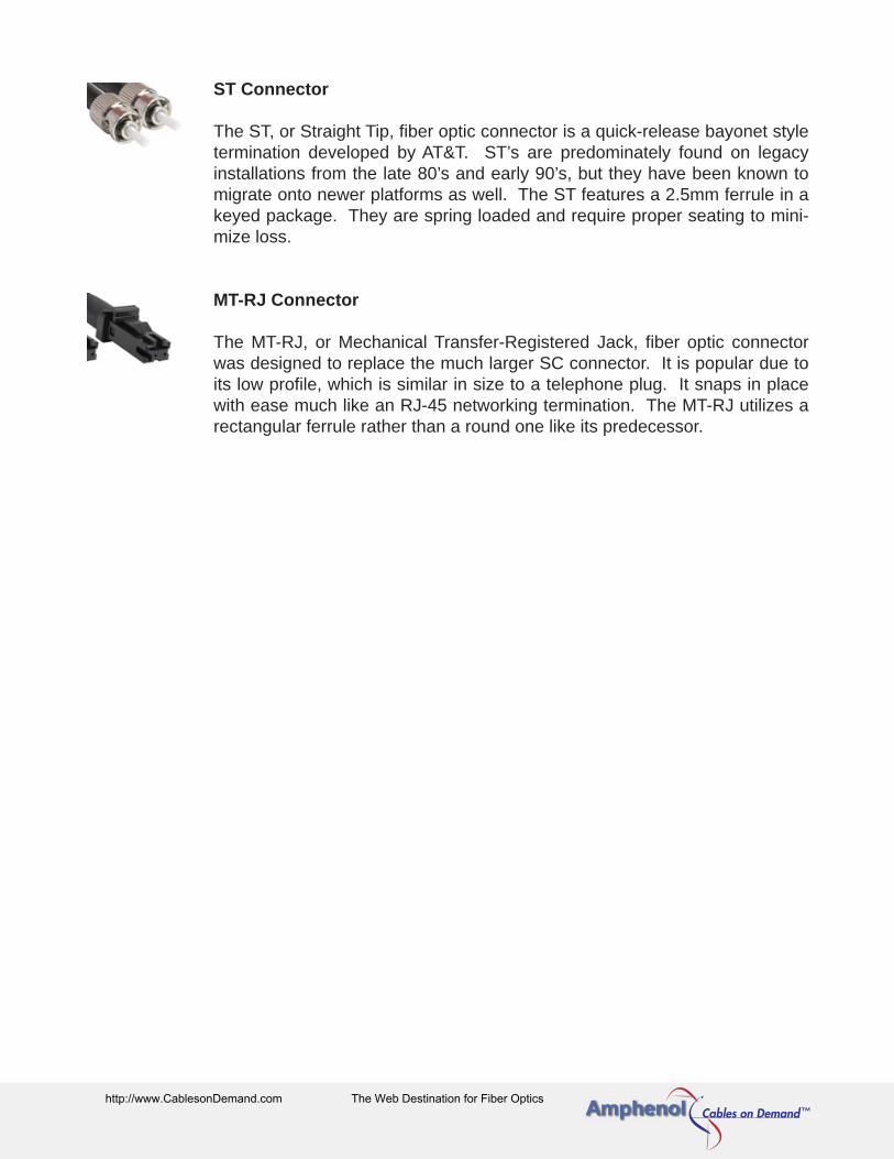