Embed Size (px)
Citation preview

Fiber Optic Cable Pipeline Leak Detection Systems for Arctic & Cold Region Applications
Prem Thodi, Mike Paulin, Duane DeGeer & Craig Young INTECSEA
November 18-19, 2014

Who we are
Experience with Arctic leak detection systems
Arctic pipeline leak detection challenges
Fiber Optic Cable DTS and DAS
Principles of operation
Key technology gaps
Arctic Leak Detection JIP
Summary
Outline
2

Significant undiscovered oil & gas reserves remain in the Arctic
Demand for oil and gas will continue to drive Arctic development
Unique Arctic environment presents technical challenges
Reliable Arctic operational strategies are needed to reduce risk
Rapid and reliable leak detection is an important aspect of safe and economic hydrocarbon development in offshore Arctic/cold regions
3
Introduction
3

Pipeline Leak Detection Systems
Conventional flow-based pipeline monitoring systems (mass balance, transient pressure wave, acoustic detection)
Airborne and marine surveillance
Leak detection procedures under winter sea ice
External monitoring systems (FO cables, LEOS, point source monitors)
Remote sensing systems (airborne infra-red, radar, satellite, visual, smell)
Other systems based on pipeline configuration
Preferred Subsea Leak Detection System Features
Continuous operation
Rapid detection of sub-1% leaks
Independent of flow conditions
Cost-effective, constructible & installable
Minimal false alarms
Long (>15 miles) pipeline coverage without intermediate power requirements
Installable in Arctic conditions
Proven performance in Arctic conditions
Offshore Arctic Leak Detection

Arctic Pipeline Leakage – Potential Causes & Consequences
Causes • Unique Loading Conditions
• Buried Pipelines• High bending strains• High differential Temperature• Ice gouging, thaw settlement, strudel scour, etc.
• Pipeline connections, valves, fittings, etc.• Structural degradation
• Corrosion, erosion• Fatigue cracking
• Other issues• Span, VIV, buckling, rupture
Consequences• Safety• Environmental• Economical• Negative reputation
Structural Degradation - Corrosion
5Compressive pipe buckle failure
Exacerbated by remoteness

INTECSEA Experience with Leak Detection Systems
Beaufort Sea Pipeline Projects:
BPXA Northstar (installed 2000)
Oil Transmission lines: Mass Balance, Pressure Balance, LEOS
Gas transmission lines: Mass balance, Pressure Balance
Pioneer Oooguruk (installed 2007)
3 Phase Production flowline: Pressure Balance, PIP annulus monitoring
Water injection flowline: Mass Balance, Pressure Balance
Gas Injection Flowline: Mass Balance, Pressure Balance
Seabed erosion: Distributed temperature sensing (DTS)
Eni Nikaitchuq (installed 2009)
3 Phase Production flowline: PIP annulus monitoring, PSL
Water injection flowline: Mass Balance, Pressure Balance
Gas Injection Flowline: Mass Balance, Pressure Balance
Seabed erosion: Distributed temperature sensing (DTS)
6
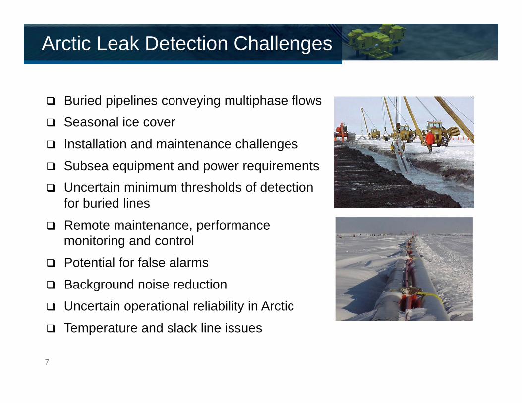
Arctic Leak Detection Challenges
Buried pipelines conveying multiphase flows Seasonal ice cover Installation and maintenance challenges Subsea equipment and power requirements Uncertain minimum thresholds of detection
for buried lines Remote maintenance, performance
monitoring and control Potential for false alarms Background noise reduction Uncertain operational reliability in Arctic Temperature and slack line issues
7
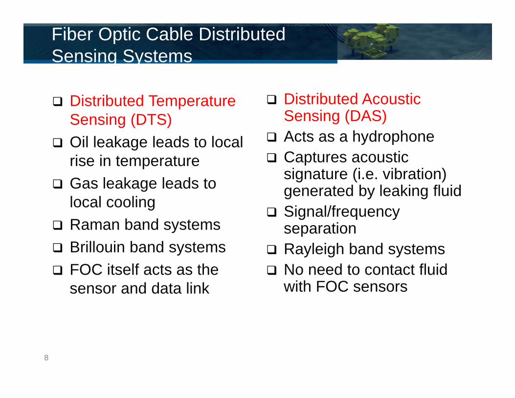
Distributed Temperature Sensing (DTS)
Oil leakage leads to local rise in temperature
Gas leakage leads to local cooling
Raman band systems Brillouin band systems FOC itself acts as the
sensor and data link
Distributed Acoustic Sensing (DAS)
Acts as a hydrophone Captures acoustic
signature (i.e. vibration) generated by leaking fluid
Signal/frequency separation
Rayleigh band systems No need to contact fluid
with FOC sensors
Fiber Optic Cable Distributed Sensing Systems
8
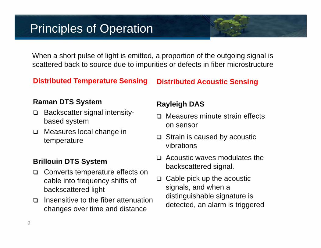
Principles of Operation
Distributed Temperature Sensing
Raman DTS System Backscatter signal intensity-
based system Measures local change in
temperature
Brillouin DTS System Converts temperature effects on
cable into frequency shifts of backscattered light
Insensitive to the fiber attenuation changes over time and distance
9
Distributed Acoustic Sensing
Rayleigh DAS Measures minute strain effects
on sensor Strain is caused by acoustic
vibrations Acoustic waves modulates the
backscattered signal. Cable pick up the acoustic
signals, and when a distinguishable signature is detected, an alarm is triggered
When a short pulse of light is emitted, a proportion of the outgoing signal is scattered back to source due to impurities or defects in fiber microstructure

FOC Distributed Sensing Leak Detection System Components
1. HDPE outer sheath2. Galfan high strength steel wire3. Gel-filled metal loose tube SS 316L4. Bend insensitive optical fibers
1. PA Outer sheath2. Stainless steel 316 L metal tube3. Inner interlocking system 4. Multilayer acoustic coupling layer5. Bend insensitive optical fiber
Typical DTS Cable
Typical DAS Cable
10
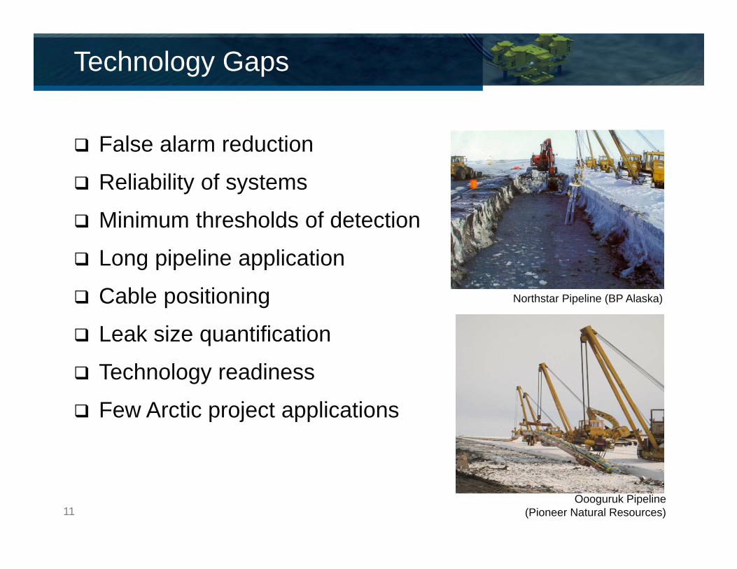
False alarm reduction
Reliability of systems
Minimum thresholds of detection
Long pipeline application
Cable positioning
Leak size quantification
Technology readiness
Few Arctic project applications
Technology Gaps
Oooguruk Pipeline (Pioneer Natural Resources)
Northstar Pipeline (BP Alaska)
11

Testing of Fiber Optic Cable Distributed Sensing Leak Detection Systems for Arctic and Cold Region Applications
Managed by Petroleum Research Newfoundland Labrador (PRNL) Not-for-profit corporation that funds and facilitates collaborative
R&D on behalf of Newfoundland and Labrador’s offshore oil and gas industry.
Lead by INTECSEA Governmental and Industry funding Phased Development
Phase 1: finishing 2014 Phase 2: 2015 -2016 (planned)
INTECSEA JIP

No comprehensive full scale testing has been reported in the public domain for FOC subsea Arctic applications
Purpose of this JIP is to help close the technology gap
Introduction & Background
General Test Setup
13
Test detectability limits Determine minimum thresholds of detection (leak rate and response
time) Help advance the technology readiness level Simulate cold-region environmental testing Identify/quantify false alarm rate Phase 1 Objectives
Planning, design and costing to establish the basis of the testing program (in Phase 2)
Develop experiment setup, test matrix and procedure, Phase 2 test organization and execution plan, Cost and schedule This will allow Phase 2 to proceed with greater confidence in the
execution, cost and schedule associated with the FOC LDS experiment program
JIP Objectives
14

Phase 1 Objectives
Phase 2 Testing
Cost• Develop Cost
and Schedule for Phase 2
Design• Test Tank
Design• Overall
Experimental Setup
Planning• Test Procedure• Execution Plan

Outline desired test parameters Particular consideration is given to testing of a long FOC
length (40km), moderate test pipe length (20m) and a low ambient temperature (4°C / 1°C)
Definition of Physical Test
Parameters Value
Pipeline Length 2m – 20m
Water Depth (max/min) 100m / 1500m (simulated)
Pipeline OD 12” (324mm)
Concrete Weight Coating Thickness 25.4mm (1”)
Fluid Type (oil/gas) Water and Nitrogen
Pipeline Design Pressure 5800psig
Pipeline Operating Temperature 0 to 50°C
Ambient Temperature 4°C (with potential of testing 1°C)
Burial Non-buried and 1m burial cases
16
Testing hierarchy: Liquid Temp Pressure Leak Size
Gas Pressure Temp Leak Size
Test procedure: Installation of test setup
Insulation/isolation
Soil preparation
Test matrix (varying pressure, temperature, leak size)
Test procedure, monitoring and control equipment
HSE considerations
Test Hierarchy & Procedure
17

Study was completed on potential test facilities/space selections.
Study Methodology: Facility identification (within JIP project area) Selection criteria (size, cost, boundary effects) Identify required modifications (i.e. insulation to minimize
boundary effects) Facility ranking
Identified 2 facilities Facility 1: Requires purpose built tank (allows testing of 2m long
pipeline segment) Facility 2: Existing tank (allows testing of 18-19m long pipeline
segment)
Test Facility Selection
18
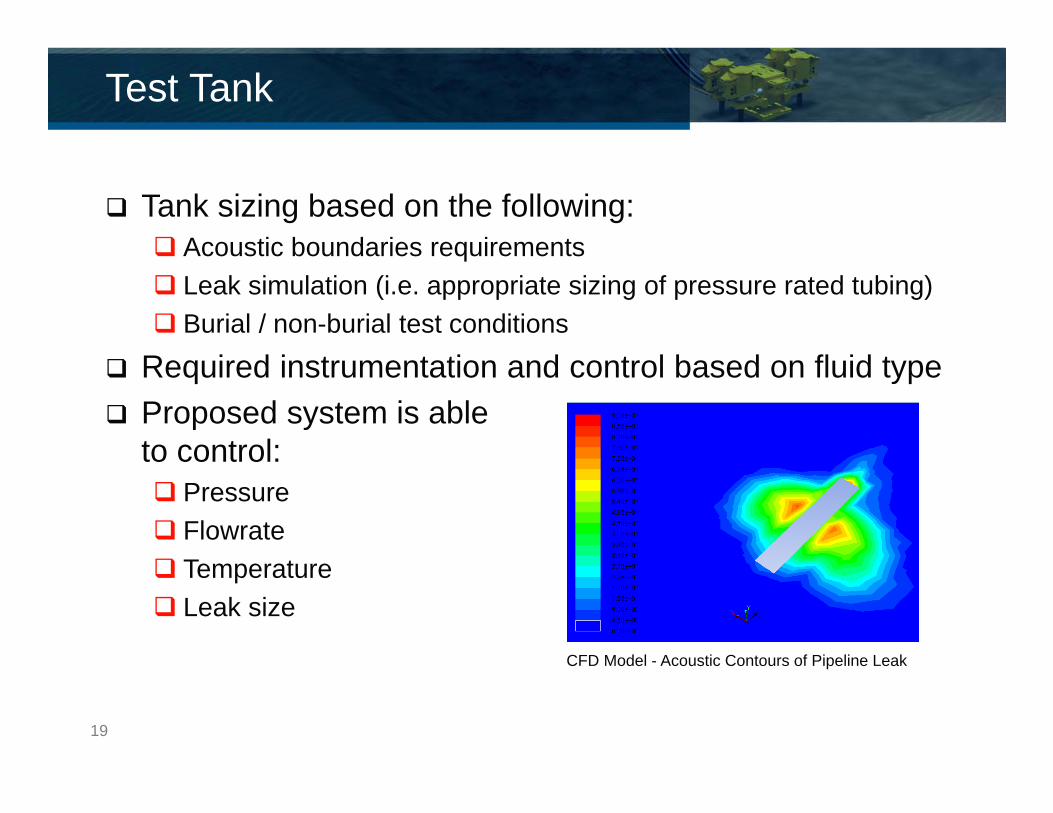
Tank sizing based on the following: Acoustic boundaries requirements Leak simulation (i.e. appropriate sizing of pressure rated tubing) Burial / non-burial test conditions
Required instrumentation and control based on fluid type Proposed system is able
to control: Pressure Flowrate Temperature Leak size
Test Tank
CFD Model - Acoustic Contours of Pipeline Leak
19
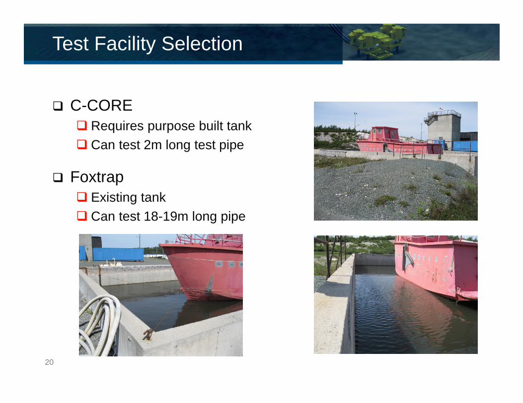
C-CORE Requires purpose built tank Can test 2m long test pipe
Foxtrap Existing tank Can test 18-19m long pipe
Test Facility Selection
20

FOC Vendor Screening Study
Vendor Identification• 14 vendors were identified
Outlined Required System Criteria• Water depth, fluid type, pipeline length, etc.
Literature Review• Through internet search and past project experience • Questionnaire provided to vendors
Level I Screening• Determine relevancy to JIP
Level II Screening• Investigation of system performance
21
Determine optimal positions to ensure baseline for detection performance can be achieved, as well as detection envelopes can be established
Positioning based on: Leak conditions
Buried/non-buried, gas/water leak Vendor recommendations
Testbed Geotechnical Evaluation Identify appropriate soil material, density and saturation
requirements, and soil placement/replacement strategy Identify testbed material as representative of Arctic and
cold region soil conditions Identify potential local vendors
FOC Positioning & Geotech Study
22
Conduct detailed engineering and procurement Execute the leak detection test program Determine detectability and detection envelope of
selected/leading DTS as well as DAS systems Further prove the technology (and enhance TRL or
reduce TRC) for Arctic and cold region applications Perform system installation, maintenance and repair
requirement assessment Evaluate system reliability and false alarm rate Recommend proven systems (DTS/DAS) for field test
and/or pilot project implementation
Phase 2 Objectives
23

Novelties
Long cable (up to 40 km)
Low ambient temperature (as low as 4°C / 1°C)
Large test tank (20m x 10m x 2.5m) Accommodation of boundary conditions
Buried pipeline
Integrated (DTS/DAS) leak testing
Small chronic leak detection capability testing
Replicate coated conditions Concrete vs. bare pipe
24

Contacts
Prem Thodi: [email protected]
Mike Paulin: [email protected]
Duane DeGeer: [email protected]
Craig Young: [email protected]