Embed Size (px)
Citation preview

CHAPTER 11
IGNITION SYSTEMSIncluding Digiplex and Microplex
purpose of the ignition system beingto initiate combustion, it is vital that thesystem an electrical discharge(spark) of the necessary intensity atright place in the firing cycle. If the sparkis too particularly theis rich or the cylinder pressure is theengine will not run. If the spark occurs inthe wrong place, at power will lost,and at worst, damage may occur.
To create a spark (which is the means ofinitiation of the explosion of the fuel/airmixture) requires a potential (voltage)difference to exist between the positive
electrode of the spark and negative, earth electrode, ie the body
of the plug. The andmore advanced modern systems allemploy a transformer coil to generate thisdischarge at the plug. The primary andsecondary coils are woundaround an iron core, and whento the primary is switched off, collaps-ing magnetic field a current to be
in secondary windings. Themeans of switching can be either by asimple contact-breaker, which is actuatedat a speed to match the cycle (halfengine speed for the four-stroke TC), orby a system
closes to charge upthe primary windings of the coil; and this
is known as the period(measured in degrees or percent). When itopens, arcing tends to occur across thecontacts as the current the primarywinding opposes this change of conditionand a capacitor isacross the points to absorb this current.When the points again, capacitordischarges the coil, so tobuild up the primary current. It is a factthat a greater current is bycollapsing the primary field thancreating it, thus it should be remembered,when timing a TC, that thespark occurs when the contact-breakeropens.
The problems with a contact-breaker
system are that the system is operated atfull battery voltage, using a large currentdrawn from main starting system; thatthe performance of the points atengine speed is by the inabilityof the spring to controlthe system accurately. The points them-selves are subject to wear, and since
some minor arcing occursacross them, on a well-maintainedsystem, the points to closingup in the process and affectingperiod/timing.
systems overcame thesepitfalls; a very low switchingcurrent is required, almost mainte-
and the intensity and duration ofthe spark is greater.
The earlier used asystem; ignition (transistorized)was introduced on the 132 131versions, plus certain Lancia models inthe The ignitionswere basically of two In the Boschsystem, a four-blade reluctorrotates around an inner coil tothe switching current; as each of the
reluctor arms passes the pickup in thedistributor the current is fed to theamplifier unit. With system,the reluctor is a steel four-lobe rotor, butit the current a similar way.
Dwell variations can occur on adistributor due to worn bearings,
if it is of the type with thecentrifugal weights mounted above theCB points baseplate. Similarly, the perfor-mance of the points can cause
to alter at high It istherefore, to examine the dwell witha and ensure that at both andlow rpm it falls within the stated data,than to set them with a feeler gauge and
for the of electronicignition dwell variation.
Useful data to CBDwell angleCB points gapCoil resistance
primary
secondary
52-58
MarelliBoschMarelli ±400
Diagrammatic layout of ignition coil and contact breaker system.
137
IGNITION SYSTEMS
200 A Bosch 0.227.100.014 ignitionFiring order
DISTRIBUTORMake Marclli Bosch
SM 801 AX 0.237.001.002 rotor and 0.40mm
Ignition coil winding ofelectromagnetic impulse at 730 ± 7 fi ± 10
RESISTOR Bosch 0.227.900.002
Resistance ± 0.05 Q
IGNITION COIL Marclli Bosch
Type BAE 207 A 0.221.122.012Ohmic resistance of primary at 20°C 0.75 ± 0.81 Q 1.2 ±
resistance of secondary at 9500 500 Q 6000 10 000
11/2: Electronic ignition technical for Fiat
electronic systems 11/4)
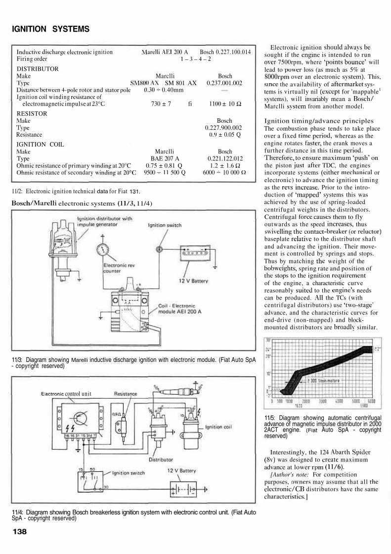
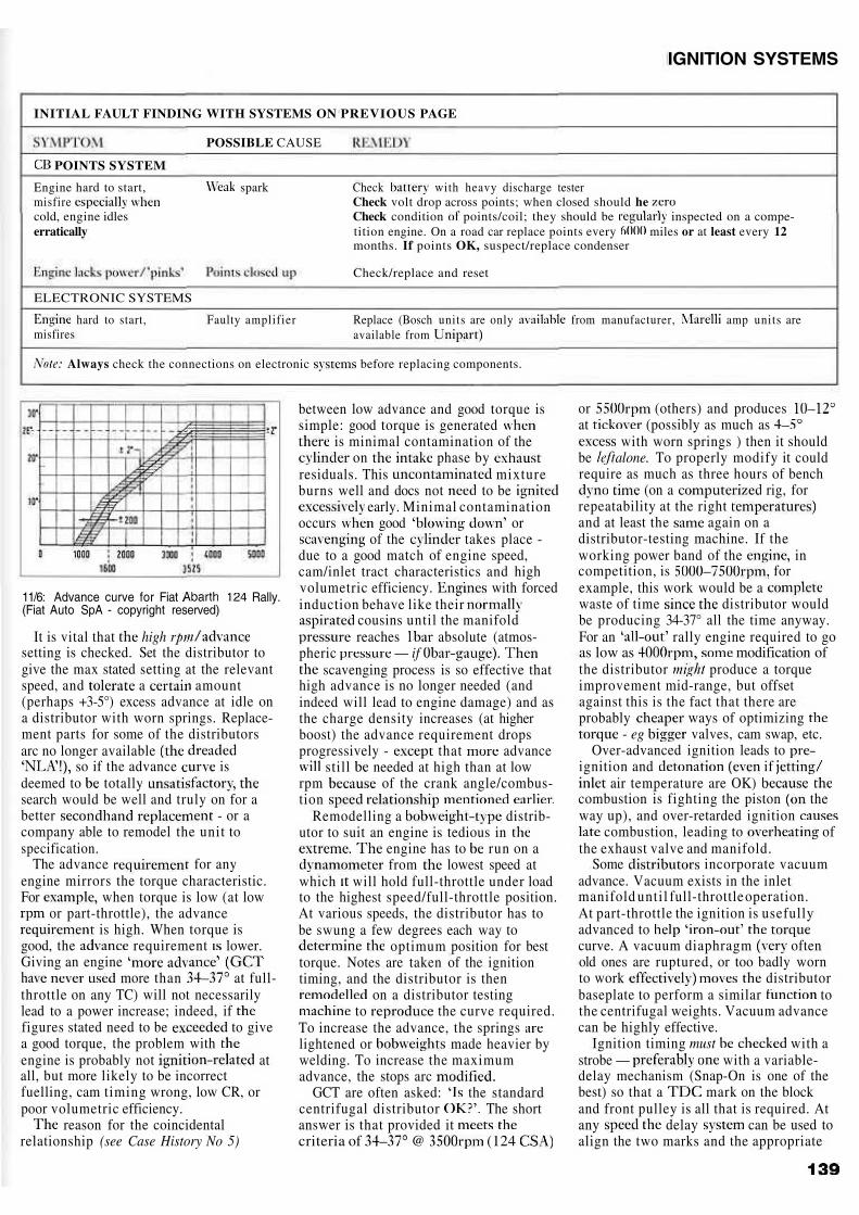
control unit
Electronic ignitionsought if the is intended to run
7500rpm, where willlead to loss (as much as 5% at
over an electronic This, the availability of sys-
tems is virtually nil for 'mappable1
systems), will invariably mean aMarclli from another model.
Ignition timing/advance principlesThe combustion phase tends to take placeover a fixed whereas as theengine rotates the erank moves afurther distance in this time
to ensure maximum onthe piston TDC, the enginesincorporate systems orelectronic) to advance the ignition timingas the Prior to the intro-duction of systems this wasachieved by the use of spring-loadedcentrifugal weights in the distributors.Centrifugal them to flyoutwards as the speed thus
(orbaseplate to the distributor shaftand advancing the ignition. Their move-ment is controlled by springs and stops.Thus by matching weight of the
spring rate and position of stops to the ignition
of the engine, a characteristic curvereasonably to the needscan be produced. the TCs (withcentrifugal distributors) useadvance, and the characteristic curves forend-drive (non-mapped) and block-mounted distributors are similar.
11/3: Diagram showing inductive discharge ignition with electronic module. (Fiat Auto SpA- copyright reserved)
11/5: Diagram showing automatic centrifugaladvance of magnetic impulse distributor in 20002ACT engine. Auto SpA - copyrightreserved)
Interestingly, the 124 was designed to maximum
advance at lower[Author's note: For competition
purposes, may assume that all distributors have the same
11/4: Diagram showing Bosch breakerless ignition system with electronic control unit. (Fiat AutoSpA - copyright reserved)
138
IGNITION SYSTEMS
INITIAL FAULT FINDING WITH SYSTEMS ON PREVIOUS PAGE
POSSIBLE CAUSE
POINTS SYSTEM
Engine hard to start,misfirecold, engine idleserratically
spark Check with heavy discharge testerCheck volt drop across points; when closed should heCheck condition points/coil; they should be inspected on a compe-tition engine. On a road car replace points every miles or at least every 12months. If points OK, suspect/replace condenser
Check/replace and reset
ELECTRONIC SYSTEMS
hard to start,misfires
Faulty amplifier Replace (Bosch units are only from manufacturer, amp units areavailable from
Always check the connections on electronic before replacing components.
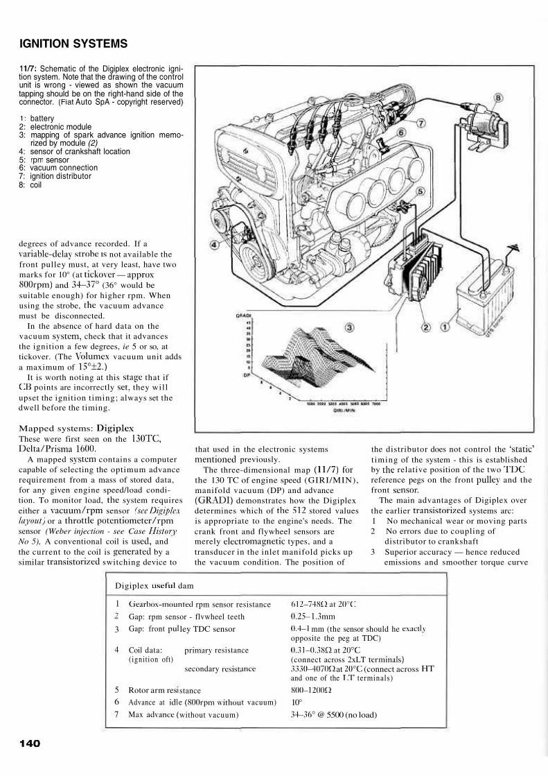
11/6: Advance curve for Fiat Rally.(Fiat Auto SpA - copyright reserved)
It is vital that highsetting is checked. Set the distributor togive the max stated setting at the relevantspeed, and a amount(perhaps +3-5°) excess advance at idle ona distributor with worn springs. Replace-ment parts for some of the distributorsarc no longer available
so if the advance isdeemed to totallysearch would be well and truly on for abetter - or acompany able to remodel the unit tospecification.
The advance for anyengine mirrors the torque characteristic.For when torque is low (at low
or part-throttle), the advance is high. When torque is
good, the requirement lower.Giving an engine
more than at full-throttle on any TC) will not necessarilylead to a power increase; indeed, iffigures stated need to be to givea good torque, the problem withengine is probably not atall, but more likely to be incorrectfuelling, cam timing wrong, low CR, orpoor volumetric efficiency.
reason for the coincidentalrelationship (see Case History No 5)
between low advance and good torque issimple: good torque is generated
is minimal contamination of the on phase by
residuals. This mixtureburns well and docs not to be
early. Minimal contaminationoccurs good or
of the takes place -due to a good match of engine speed,cam/inlet tract characteristics and highvolumetric efficiency. with forcedinduction behave like their
cousins until the manifold reaches absolute (atmos-
pheric — if scavenging process is so effective that
high advance is no longer needed (andindeed will lead to engine damage) and asthe charge density increases (at higherboost) the advance requirement dropsprogressively - that advance
still needed at high than at lowrpm of the crank angle/combus-tion
Remodelling a distrib-utor to suit an engine is tedious in
engine has to run on a from lowest speed at
which will hold full-throttle under loadto the highest speed/full-throttle position.At various speeds, the distributor has tobe swung a few degrees each way to
optimum position for besttorque. Notes are taken of the ignitiontiming, and the distributor is then
on a distributor testing to the curve required.
To increase the advance, the springslightened or made heavier bywelding. To increase the maximumadvance, the stops arc
GCT are often asked: the standardcentrifugal distributor The shortanswer is that provided itcriteria of @ (124
or (others) and producesat (possibly as much as
with worn springs ) then it shouldbe alone. To properly modify it couldrequire as much as three hours of bench
(on a rig, forrepeatability at the rightand at least the again on adistributor-testing machine. If theworking power band of the incompetition, is forexample, this work would be awaste of time distributor wouldbe producing 34-37° all the time anyway.For an rally engine required to goas low as modification ofthe distributor produce a torqueimprovement mid-range, but offsetagainst this is the fact that there areprobably ways of optimizing
- eg valves, cam swap, etc.Over-advanced ignition leads to
ignition and if air temperature are OK)
combustion is fighting the piston theway up), and over-retarded ignition
combustion, leading to ofthe exhaust valve and manifold.
Some incorporate vacuumadvance. Vacuum exists in the inletmanifold until full-throttle operation.At part-throttle the ignition is usefullyadvanced tocurve. A vacuum diaphragm oftenold ones are ruptured, or too badly wornto work distributorbaseplate to perform a similar tothe centrifugal weights. Vacuum advancecan be highly effective.
Ignition timing must with astrobe — with a variable-delay mechanism (Snap-On is one of thebest) so that a mark on the blockand front pulley is all that is required. Atany delay can be used toalign the two marks and the appropriate
IGNITION SYSTEMS
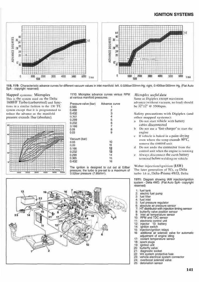
Schematic of the Digiplex electronic igni-tion system. Note that the drawing of the controlunit is wrong - viewed as shown the vacuumtapping should be on the right-hand side of theconnector. Auto SpA - copyright reserved)
battery2: electronic module3: mapping of spark advance ignition memo-
rized by module (2)4: sensor of crankshaft location5: sensor6: vacuum connection7: ignition distributor8: coil
degrees of advance recorded. If a not available the
front pulley must, at very least, have twomarks for 10° (at —
and (36° would besuitable enough) for higher rpm. Whenusing the strobe, vacuum advancemust be disconnected.
In the absence of hard data on thevacuum check that it advancesthe ignition a few degrees, ie 5 or so, attickover. (The vacuum unit addsa maximum of
It is worth noting at this that if points are incorrectly they will
upset the ignition timing; always set thedwell before the timing.
Mapped systems:These were first seen on the
A mapped contains a computercapable of selecting the optimum advancerequirement from a mass of stored data,for any given engine speed/load condi-tion. To monitor load, system requireseither a sensor
or asensor (Weber injection - see CaseNo 5), A conventional coil is andthe current to the coil is by asimilar switching device to
that used in the electronic systems previously.
The three-dimensional mapthe 130 TC of engine speed (GIRI/MIN),manifold vacuum (DP) and advance
demonstrates how the Digiplexdetermines which of stored valuesis appropriate to the engine's needs. Thecrank front and flywheel sensors aremerely types, and atransducer in the inlet manifold picks upthe vacuum condition. The position of
the distributor does not control thetiming of the system - this is establishedby relative position of the tworeference pegs on the front and thefront
The main advantages of Digiplex overthe earlier systems arc:1 No mechanical wear or moving parts2 No errors due to coupling of
distributor to crankshaft3 Superior accuracy — hence reduced
emissions and smoother torque curve
Digiplex dam
17
3
4
56
7
rpm sensor resistance
Gap: rpm sensor - flvwheel teeth
Gap: front
Coil data:(ignition oft)
Rotor arm res
Advance at
Max
ley TDC sensor
resistance
secondary
stancee vacuum)
without vacuum)
mm (the sensor should heopposite the peg at TDC)
(connect across 2xLT at (connect across
and one of the terminals)
10°
@ 5500 (no load)
HT
IGNITION SYSTEMS
0 . 2000 3000 4000 5000
Characteristic advance curves for different vacuum values in inlet manifold: Hg; right, Hg, (Fiat AutoSpA - copyright reserved)
systems:This is system used on
andtions in a similar fashion to the 130system except that it is programmed toreduce the advance as the manifold
11/10: Microplex advance curves versusat various manifold pressures.
Pressure valve (bar)0.5650.4980.4320.3650.2990.232
0.090.03
Vacuum (bar)0.030.090.1660.2320.2990.3650.432
Advance curve123456789
10111213141516
The ignition is designed to cut out at 0,6barpressure; the turbo is pre-set to a maximum of
pressure
Same as Digiplex maximumadvance (without vacuum, no load) shouldbe @ 5500rpm.
Safety precautions with Digiplex (andother mapped systems):a Do not start with
cablesb Do not use a to start the
enginec If vehicle is baked in a
oven where the tempremove the unit
d Do not undo the from thecontrol unit when the engine is running
e Always disconnect earthterminal welding on vehicle
Weber injection/ignitionThe later generation of TCs, egturbo 1.6 Delta
11/11: Diagram showing IAW injection/ignitionsystem - Delta 4WD. (Fiat Auto SpA - copyrightreserved)
tank2: electric fuel pump3: fuel filter4: fuel inlet5: fuel pressure regulator6: absolute air pressure sensor7: HT distributor with injection timing sensor8: butterfly valve position sensor9: inlet air temperature sensor
10: RPM and TDC sensor electronic control unit
12: injector 13: battery14: ignition switch15: injection/ignition relays16: additional air solenoid valve for automatic
adjustment of engine idling17: coolant temperature sensor18:19: ignition unit20: butterfly valve21: diagnostic socket22: system protective fuse23: vehicle electrical system connector24; overboost solenoid valve25: detonation sensor
141