Embed Size (px)
Citation preview

TASEKO MINES LIMITED
GEOTECHNICAL DIAMOND DRILLING
ASSESSMENT REPORT
F I to F9, Fish I and Fish 5 to Fish I 1
MINERAL CLAIMS
FISH LAKE PROPERTY
Clinton Mining Division
British Columbia Canada
NTS 920/5E
Latitude 51'27' North Longitude 123'36' West
BY L. K. Brommeland, B.Sc.
R. J. Haslinger, P.Eng C. M. Rebagliati, P.Eng
January 11, 1995

TABLE OF CONTENT
0 1.0 SUMMARY . . . . . . . . . . . . . . . . . . . . . . . . 2.0 INTRODUCTION . . . . . . . . . . . . . . . . . . . . . . . . . . . . . . . . . . . . . . . 3 3.0 LOCATION AND ACCESS . . . . . . . . . . . . . . . . . . . . . . . . . . . . . . . . . 4
4.0 CLAIM DATA . . . . . . . . . . . . . . . . . . . . . . . . . . . . . . . . . . . . . . . . . 5
5.0 EXPLORATION HISTORY . . . . . . . . . . . . . . . . . . . . . . . . . . . . , . . . . 6
6.0 GEOTECHNICAL DRILL PROGRAM . . . . . . . . . . . . . . . . . . . . . . . . . . . 7
7.0 CONCLUSIONS AND RECOMMENDATIONS . . . . . . . . . . . . . . . , . . . . 9
8.0 STATEMENT OF COSTS . . . . . . . . . . . . . . . . . . . . . . . . . . . . . . . . . 10
9.0 REFERENCES . . . . . . . . . . . . . . . . . . . . . . . . . . . . . . . . . . . . . . . . 11
10.0 STATEMENT OF QUALIFICATIONS 12 . . . . . . . . . . . . . . . . . . . . . . . . .
LIST OF TABLES
1. MINERAL CLAIMS REFERENCED . . . . . . . . . . . . . . . . . . . . . . . . . . . . 5
4D
Q
LIST OF FIGURES
Following Page 1. SITE LOCATION MAP . . . . . . . . . . . . . . . . . . . . . . . . . . . . . . . . . . . 4
2. PROPERTY MAP . . . . . . . . . . . . . . . . . . . . . . . . . . . . . . . . . . . . . . , 5
3. SITE LAYOUT SHOWING GEOTECHNICAL DRILL HOLE LOCATIONS . . . 7
4. CLAIM MAP SHOWING GEOTECHNICAL DRILL HOLE LOCATIONS . . . . 7
LIST OF APPENDICES
1. CLAIMS HELD BY TASEKO MINES LIMITED
I I . 1994 GEOTECHNICAL AND HYDROGEOLOGICAL INVESTIGATIONS FOR PROPOSED TAILINGS STORAGE FACILITY, FISH LAKE PROJECT, BY KNIGHT PIESOLD LTD.

1
1.0 SUMMARY
The Fish Lake Property, owned by Taseko Mines Limited, is located approximately
250 kilometres north of Vancouver, and 125 kilometres southwest of the community
of Williams Lake, British Columbia, situated in the Clinton Mining Division. The 95
square kilometre property is comprised of 196 mineral and 9 placer claims.
Road access is via the Bella Coola Highway (Highway 20) from Williams Lake to the
community of Hanceville, then southwest along a government maintained gravel road.
The property is also accessible by fixed wing aircraft equipped with floats or skis to
Fish Lake located approximately 10 kilometres north of Taseko Lake.
Exploration by numerous operators including Bethlehem, Cominco, Nittetsu, Quintana
and Taseko Mines during the period 1960 - 1994 culminated in the discovery and
definition of a Cu-Au prophyry deposit. The deposit has been defined by a cumulative
0
total of 73, 644 meters in 238 holes and contains a geological resource of 976 million
tonnes grading 0.23% copper and 0.48 grams goldkonne.
A program of geotechnical-geological HQ diameter drilling totalling 425.48m in six
holes was conducted to the south of the main deposit area during July and August,
1994. The holes were drilled to evaluate both the economic and mineral potential as
well as the geological and hydrogeological conditions along the west and south sides
of the proposed tailings impoundment area.

2
The holes intersected a bedrock sequence comprised of Miocene basalt flows and a sediments as well as Upper Cretaceous Kingsvale sediments. Average bedrock
permeabilities ranged from to cmlsec.
The proposed tailings storage facility site requires further evaluation in order to assess
high permeability fracture zones and availability/continuity of low permeability glacial
till materials.

3 Q 2.0 INTRODUCTION
The Fish Lake copper-gold porphyry deposit lies approximately 125 km southwest of
Williams Lake, BC. The Fish Lake property, covering the deposit area, incorporates
a total of 196 mineral claims and 9 placer claims.
Taskeo Mines Limited conducted a 35 hole diamond drilling program on the property
in 1994. This included the drilling of 29 holes in the deposit area, and 6 geotechnical-
geological holes in the area of proposed tailings embankments south of Fish Lake.
This report documents results and data collected from the 6 hole geotechnical-
geological diamond drill program performed between June 23 and September 15,
1994. This 425.48m program specifically addressed proposed tailings dam 0
embankments for hydrogeology on the Fish 1, Fish 6 and Fish 7 mineral claims.
Detailed technical information for each drill hole is contained in the appended report
by Knight Pir5sold Ltd. (Appendix It).
Q 4
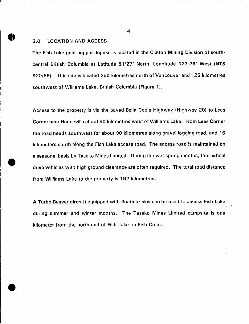
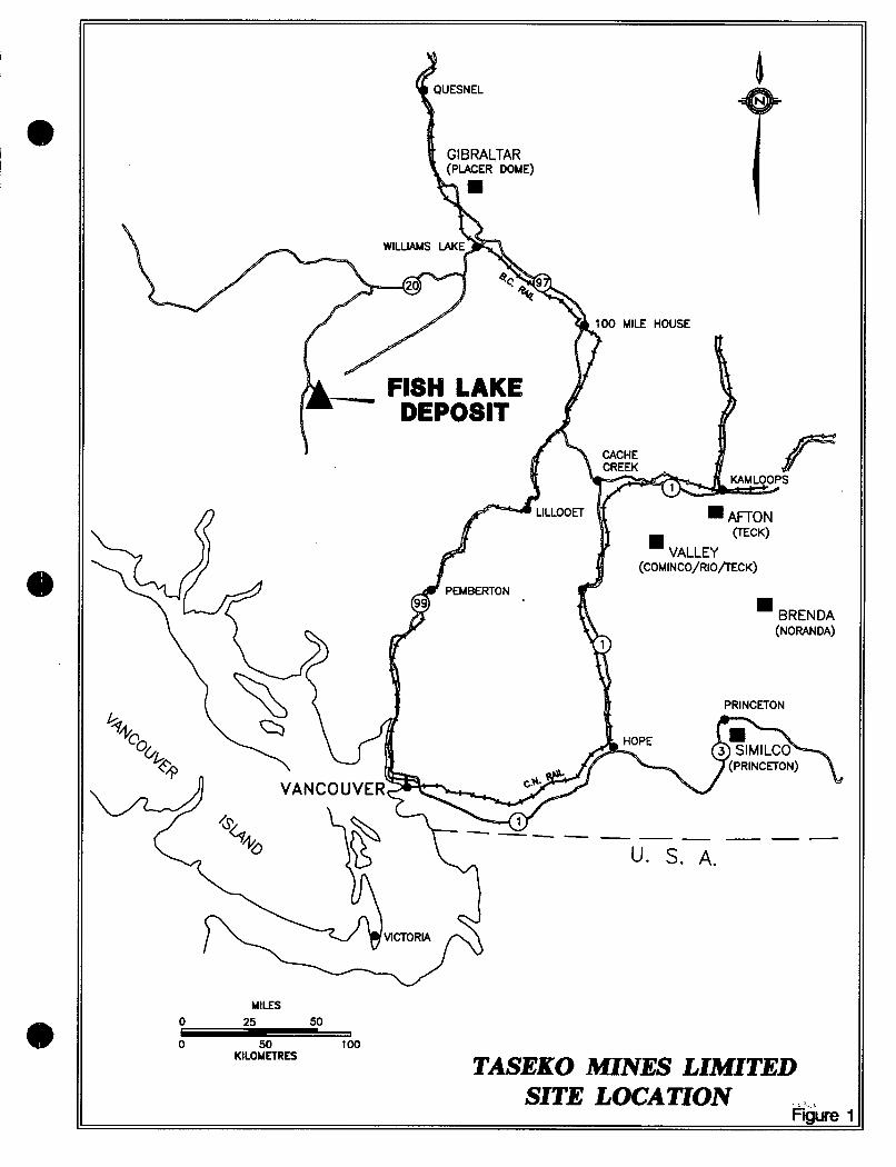
3.0 LOCATION AND ACCESS
The Fish Lake gold-copper deposit is located in the Clinton Mining Division of south-
central British Columbia at Latitude 51'27' North, Longitude 123'36' West (NTS
920/5E). This site is located 250 kilometres north of Vancouver and 125 kilometres
southwest of Williams Lake, British Columbia (Figure 1).
Access to the property is via the paved Bella Coola Highway (Highway 20) to Lees
Corner near Hanceville about 90 kilometres west of Williams Lake. From Lees Corner
the road heads southwest for about 90 kilometres along gravel logging road, and 16
kilometers south along the Fish Lake access road. The access road is maintained on
a seasonal basis by Taseko Mines Limited. During the wet spring months, four-wheel
drive vehicles with high ground clearance are often required. The total road distance 0
from Williams Lake to the property is 192 kilometres.
A Turbo Beaver aircraft equipped with floats or skis can be used to access Fish Lake
during summer and winter months. The Taseko Mines Limited campsite is one
kilometer from the north end of Fish Lake on Fish Creek.
UESNEL
MILES
0 50 100 KILOMETRES TASEKO MINES LIMITED
SI= LOCATION F& 1

5
3563(1)
3 14027
314028
314029
314030.
314031
4.0 CLAIM DATA
20 18/1/91
20 15/10/92
20 16/10/92
20 17/10/92
20 17/10/92
8 16/10/92
The Fish Lake property, which is 95 square kilometres in size, is situated in the
Clinton Mining Division on N.T.S. map sheet 920/5E (Figure 2). The property, owned
by Taseko Mines Ltd., consists of 196 mineral claims totalling 548 units.
314026
314032
A list of claims data pertinent to this report appears below, with expiry dates subject
12 17/10/92 1 7/10/2000
12 17/10/92 17/10/2000
to acceptance of assessment work and credits supported by this report. A complete
314005
3 14006
list of claims is provided as Appendix I .
1 16/10/92 1 6/ 1 0/2000
1 16/10/92 16/10/2000
11 CLAIM NAME
314025
Fish 1
Fish 5
1 16/10/92 16/10/2000
11 Fish 6
I/ Fish 7
Fish 8
Fish 10
Fish 11 k-
11 F6
IF7
TABLE 1 - MINERAL CLAIMS REFERENCE1
TENURE NO. 1 UNITS I RECORD DATE EXPIRY DATE
18/1/2000
15/10/2000
16/10/2000
17/10/2000
17/10/2000
16/10/2000
314003 I 1 I 15/10/92 I 15/10/2000 11 314004 I 1 I 15/10/92 I 1511 0/2000 11
3 14007 I 1 I 16/10/92 I 16/10/2000 11 3 14008 I 1 I 16/10/92 I 16/10/2000 11 314009 I 1 I 16/10/92 I 16/10/2000 11
_ _ _ _ _ _ ~ ~
314010 I 1 I 16/10/92 1 16/10/2000 11

8
a
BOUNDARY
0 i 2 3 4 KILOMETRES
TASEKO MZNES LLMITED
Figure 2 PROPERTY MAP

6
5.0 EXPLORATION HISTORY
In the early 1930's, prospectors E. Calep and C.M. Vick followed mineralized float and
located exposures of pyrite and chalcopyrite-bearing diorite and feldspar porphyry
dykes, approximately 1 kilometre east and 0.5 kilometres north of the Fish Lake
deposit proper. In 1960, the porphyry copper potential of the area was recognized
by Phelps Dodge Corporation. Early drilling results were not sufficiently encouraging
and Phelps Dodge allowed the claims to lapse. In 1969, Taseko Mines Limited
acquired the ground, drilled approximately 2,200 metres in 18 holes and discovered
better grade mineralization. The property was then optioned to Nittetsu Mining
Company Ltd. (1 970) and later to Quintana Minerals Corporation, which in 1973 and
in 1974 drilled approximately 6,000 metres in 23 core holes in order to test and
delineate the areas of better-grade mineralization. Further work by Bethlehem Copper
(1 979-1 981) and more recently by Cominco Ltd. (1 982-1 989) expanded the known
deposit size. In 1990, the drill indicated resource was estimated at 203 million tonnes
grading 0.24% copper and 0.48 grams goldhonne.
During 1991 and 1992, Taseko Mines Limited, diamond drilled a total of 67,783 m
in 122 holes and increased the drill indicated resource to 976 million tonnes grading
0.23% copper and .48 grams gold/tonne (1075 million tons a t 0.23% copper and
0.013 oz/ton gold).

6.0 GEOTECHNICAL DRILL d
A program of diamond drilling,
7
PROGRAM
comprising a total of 425.48m in 6 HQ diameter holes,
was completed on the Fish 1, Fish 6 and Fish 7 mineral claims during the period June
23 to September 19, 1994. The drilling was conducted with a Val d'Or 2000
hydraulic fly-rig. A detailed report providing drill logs, plans and cross sections is
presented as Appendix I1 to this report.
The six holes were drilled as part of an investigation of bedrock and overburden
foundation conditions in the West Embankment, West Saddle Dam and South Dam
areas of the proposed Tailings Storage Facility.
This site is currently considered to ~e
from a proposed open pit mine
be the optimum site available for storage of tailings
at Fish Lake. The holes were drilled to obtain
geological, permeability, seepage, construction material and stability information in the
embankment areas and to provide groundwater quality monitoring wells.
The six holes were each collared in glacial till. This till layer, comprised of brown
sandy clay with gravel and cobbles, was generally thin but became thicker in
topographically low areas and the area near Wasp Lake.
Underlying the glacial Miocene basalt flows and sediments were present in all holes
except 94 - 141 and 94 - 143, both of which lacked Miocene sediments. Holes 94 - e

TAILINGS STORAGE
w 0 0 0 ln -
Metres 0 500 1000 1500
0 2500 5000 -
Feet TASEKO MINES LIMITED
mure 3 SITE LAYOUT
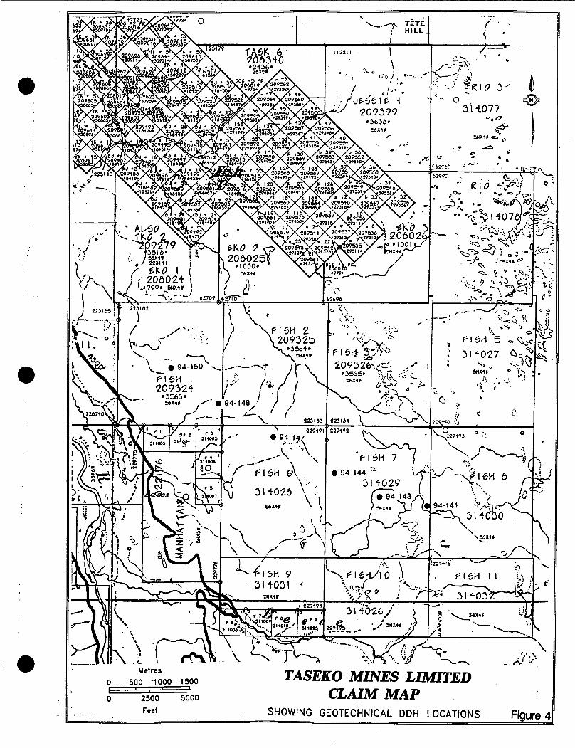
TASEKO MINES LIMITED Metres o 500 -lo00 1500
0 2500 5000 - CLAIM MAP - - - Feet SHOW I NG GEOTECH Nl CAL D DH LOCATIONS Figure 4

8
144 and 94 - 150 passed through the Miocene basalts and sediments and were e terminated in Cretaceous Sedimentary rocks.
Miocene basalt flows comprised dark greedgrey or maroon to dark brownlgrey rock
with alternating vesicular, vuggy and fine grained massive zones. Red-grey and brown
discolourations were noted. Miocene sediments comprised siltstone, sandstone,
claystone, conglomerate and some gravel lenses. Cretaceous sediments were
comprised of argillite, argillaceous siltstone and pebble conglomerate.

9
8 7.0 CONCLUSIONS AND RECOMMENDATIONS
The six hole geotechnical drilling program provided additional information on the
geology and hydrogeology of proposed tailings dam embankments along the west and
south sides of the proposed tailings impoundment area. This information was used
to evaluate the performance of proposed seepage control measures and to predict
seepage losses to groundwater as well as to confirm the stability of the proposed
West Em ban kmen t .
I f this site remains in favour as a tailings storage area, additional assessment of higher
permeability fracture zones and alluvial materials may be necessary.
Identification of high permeability areas and evaluation of continuity and thickness of
surficial, low permeability glacial till materials could be accomplished by employing
a
one or more of the following methods:
1. Surface mapping to establish basalt and till distribution.
I 2. Test pitting to determine areas of deeper overburden.
3. Appropriate geophysical testing to evaluate continuity and thickness of
glacial till.
Drilling to evaluate fracture zones and provide additional. permeability
information.
4.

8 10
8.0 STATEMENT OF COSTS
STATEMENT OF COSTS
Fish Lake Geotechnical Drill Program (July 26 - August 15, 1994)
Diamond Drilling (Quest Canada Drilling (1 991) Inc.) Drill Mob-Demob $ 6,000.00 Direct Drilling Costs 48,154.70
$ 54,154.70
Engineering (Knight Piesold Ltd) On Site Engineering/Testwork: 200 hrs @ $65/hr $1 3,000.00
$ 13,000.00
Helicopter (Canadian Helicopters) Mob-Demob: 1.4 hrs @ $850/hr Drill Moves: 16.4 hrs @ $850/hr Support 26.2 hrs @ $850/hr
4)
Camp Costs Room/Board: 126 man days @ $50/da
$ 1,190.00 13,940.00 22,270.00
$ 37,400.00
$ 6,300.00 $ 6,300.00
TOTAL COSTS $1 10,854.70
NOTE: (i)
(ii) (iii) Reclamation costs, telecommunications/courier costs, and
No administrative or supervisory costs have been included, in or out of the field. Off site engineering costs and computer time have not been included.
truck/equipment rentals have not been included.
11
9.0 REFERENCES
CAIRA, N.M., FINDLAY, A., DELONG, R.C., AND REBAGLIATI, C.M., 1995 Fish Lake Porphyry Copper-Gold Deposit, Central British Columbia. As yet unpublished CIM paper.
CAIRA, N.M. and PIROSH, D., 1992. Diamond Drilling Assessment Report on the Fish Lake Property
DELONG, R.C., HASLINGER, R.J., AND REBAGLIATI, C.M., 1995 1994 Exploration-Delineation, Geotechnical and Environmental Drilling Program on the Fish Lake Porphyry Gold Copper Deposit. Private report for Taseko Mines Limited. \
SIVERTZ, W.G., 1993 Geotechnical Diamond Drilling Assessment Report EKO 1, Fish 1 to Fish 11, and F1 to F9 Mineral Claims. Fish Lake Property.
12
10.0 STATEMENTS OF QUALIFICATIONS
STATEMENT OF QUALIFICATIONS
1.
2.
3.
4.
5.
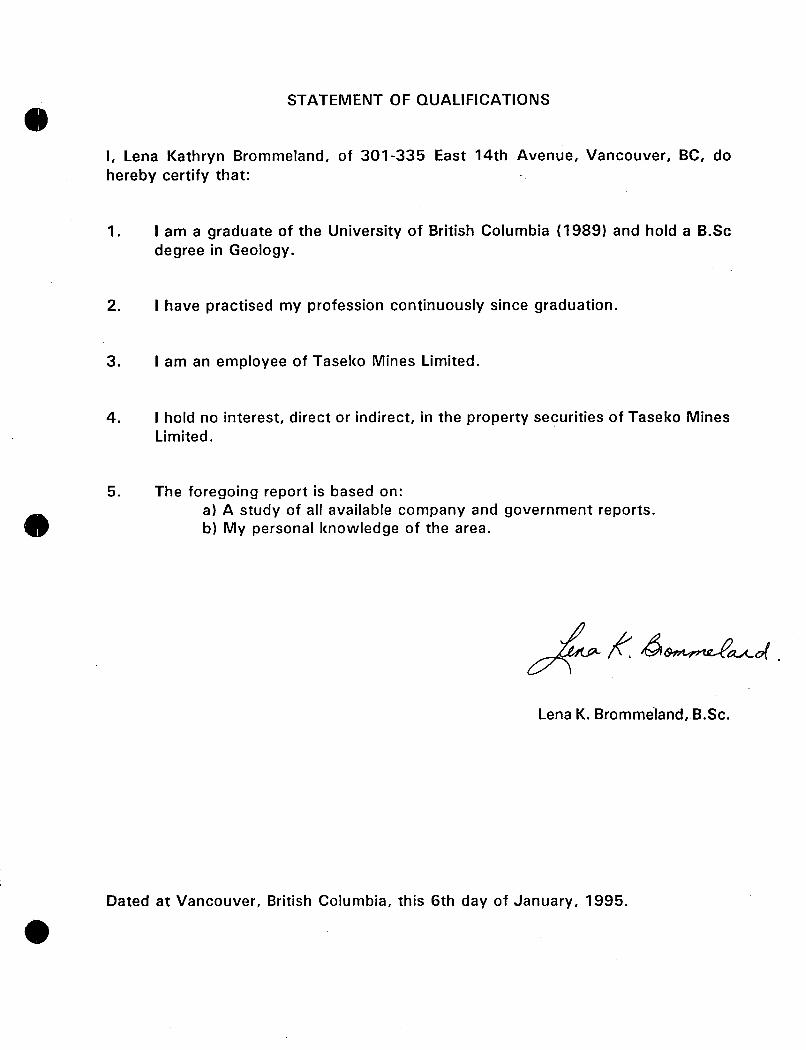
I, Lena Kathryn Brommeland, of 301-335 East 14th Avenue, Vancouver, BC, do hereby certify that:
I am a graduate of the University of British Columbia (1989) and hold a B.Sc degree in Geology.
I have practised my profession continuously since graduation.
I am an employee of Taseko Mines Limited.
I hold no interest, direct or indirect, in the property securities of Taseko Mines Limited.
The foregoing report is based on: a) A study of all available company and government reports. b) My personal knowledge of the area.
Lena K. Brommeland,.B.Sc.
Dated at Vancouver, British Columbia, this 6th day of January, 1995.

STATEMENT OF QUALIFICATIONS
0 I, Richard Josef Haslinger, of 821 West 19th Avenue, Vancouver, B.C., hereby certify that:
1. I am a Consulting Geological Engineer with offices at 821 West 19th Avenue, Vancouver, B.C.
2. 1 am a graduate of the University of British Columbia (B.A. Sc., Geological Engineering, 1986.)
3. I have practised my profession continuously since graduation, excluding the period January, 1989 to June, 1990.
4. I am a member in good standing of the Association of Professional Engineers and Geoscientists of British Columbia.
I) 5. The foregoing report is based on: a) b)
A study of all available company and government reports. My personal knowledge of the area resulting from my supervision of exploration on the property from June to October, 1994.
R.J. Haslinger, P.Eng.
a Dated at Vancouver, British Columbia, this 6th day of January, 1995.

STATEMENT OF QUALIFICATIONS
I, Clarence Mark Regabliati, of the City of Vancouver, Province of British Columbia, DO HEREBY CERTIFY THAT:
1.
2.
3.
4.
5.
6.
I am a Consulting Geological Engineer with a business office at Suite 1020, 800 West Pender Street, Vancouver, B.C.
I am a graduate of the Provincial Institute of Mining, Haileybury, Ontario (Mining Technology, 1966).
I am a graduate of the Michigan Technological University, Houghton, Michigan, U.S.A. (B.Sc., Geological Engineering, 1969).
I am a registered member, in good standing of the Association of Professional Engineers and Geoscientists of British Columbia.
I have practised my profession continuously since graduation.
I directed the 1994 exploration program on the subject property.
Dated at Vancouver, British Columbia, this 6th day of January, 1995.

APPENDIX I
CLAIMS HELD BY TASEKO MINES LIMITED

Page 1
NTS 920/5E 8)
a
e
Xnton Mining Divb
Claim Name
BCC-1 (Fr) B C C-2 (F r) B C C-3 ( F r) BC C-4 ( F r) BC C-5 ( F r) B C C -6 ( F r) BJ-1 BJ-3 BJ-5 BJ-7 BJ-9 BJ-11 BJ-13 BJ-14 BJ-15 BJ-16 BJ-17 BJ-18 BJ-19 BJ-20 BJ-21 BJ-22 BJ-23 BJ-24 BJ-25 BJ-26 BJ-27 BJ-28 BJ-29 BJ-30 BJ-31 BJ-32 BJ-33 BJ-34 BJ-35 BJ-36 BJ-37 BJ-38 BJ-39 BJ-40 BJ-41
TASEKO MINES LIMITED FISH LAKE PROJECT
MINERAL CLAIMS
Record Tenure Units Record Number Number Date
969 970 97 1 972 973 979
1841 7 18419 1 842 1 18423 18426 18427 18429 18430 18431 18432 18433 18434 18435 18436 18437 18438 18439 18440 18441 18442 18443 18444 18445 18446 18447 18448 18449 18450 18451 18452 18453 18454 18455 18456 18457
20801 5 20801 6 20801 7 20801 8 20801 9 208020 209487 209488 209489 209490 209491 209492 209493 209494 209495 209496 209497 209498 209499 209500 209501 209502 209503 209504 209505 209506 209507 209508 209509 209510 20951 1 209512 20951 3 209514 20951 5 209516 209517 20951 8 20951 9 209520 209521
1 1 1 1 1 1 1 1 1 1 1 1 1 1 1 1 1 1 1 1 1 1 1 1 1 1 1 1 1 1 1 1 1 1 1 1 1 1 1 1 1
06-Feb-81 06-Feb-81 06-Feb-81 06-Feb-81 06-Feb-81 25-Feb-8 1 25-Jun-69 25-J u n-69 25-Jun-69 25-Jun-69 25-Jun-69 25-J u n-69 25-Jun-69 25-Jun-69 25-J u n-69 25-Jun-69 25-Jun-69 25-Jun-69 25-Jun-69 25-Jun-69 25-Jun-69 25-Jun-69 25-J un-69 25-Jun-69 25-Jun-69 25-Jun-69 25-Jun-69 25-Jun-69 25-Jun-69 25- J u n-69 25-Jun-69 25-Jun-69 25-J un-69 25-Jun-69 25-Jun-69
25-Jun-69 25-Jun-69 25- J u n-69 25-J u n-69 25-Jun-69
25-Juri-69
Expiry Date
06-Feb-2000 06-Feb-2001 06-Feb-2001 06-Feb-200 1 06-Feb-2000 25-Feb-2000 25-Jun-2000 25-Jun-2000 25-Jun-2000 25-Jun-2000 25-Jun-2000 25-Jun-2000 25-J un-2000 25-J un-2000 25-Jun-2000 25-Jun-2000 25-Jun-2000 25-J u n-2000 25-Jun-2000 25-Jun-2000 25-Jun-2000 25-Jun-2000 25-Jun-2000 25-Jun-2000 25-Jun-2000 25-Jun-2000 25-Jun-2000 25-Jun-2000 25-Jun-2000 25-Jun-2000 25-Jun-2000 25-Jun-2000 25-Jun-2000 25-Jun-2000 25-Jun-2000 25-Jun-2000 25-Jun-2000 25-Jun-2000 25-Jun-2000 25-Jun-2000 25-Jun-2000
Page 2
NTS 920/5E 0
8
8
l i n t o n Mining Divb
Claim Name
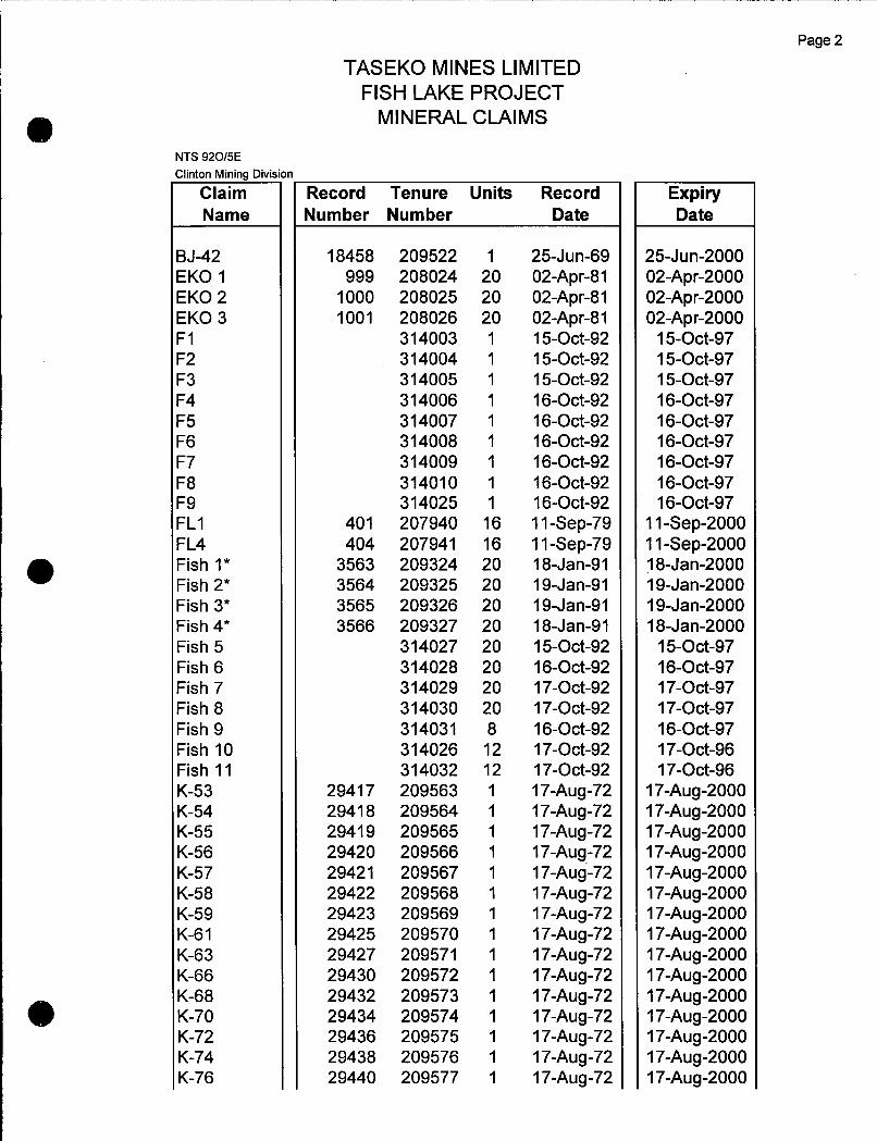
BJ-42 EKO 1 EKO 2 EKO 3 F1 F2 F3 F4 F5 F6 F7 F8 F9 FLI FL4 Fish I * Fish 2* Fish 3* Fish 4* Fish 5 Fish 6 Fish 7 Fish 8 Fish 9 Fish 10 Fish 11 K-53 K-54 K-55 K-56 K-57 K-58 K-59 K-6 1 K-63 K-66 K-6 8 K-70 K-72 K-74 K-76
TASEKO MINES LIMITED FISH LAKE PROJECT
MINERAL CLAIMS
Record Tenure Units Record Number Number Date
18458 999
1000 1001
40 1 404
3563 3564 3565 3566
2941 7 2941 8 2941 9 29420 29421 29422 29423 29425 29427 29430 29432 29434 29436 29438 29440
209522 208024 208025 208026 314003 3 14004 314005 314006 3 14007 314008 314009 314010 31 4025 207940 207941 209324 209325 209326 209327 3 14027 314028 314029 31 4030 314031 31 4026 31 4032 209563 209564 209565 209566 209567 209568 209569 209570 209571 209572 209573 209574 209575 209576 209577
1 20 20 20 1 1 1 1 1 1 1 1 1 16 16 20 20 20 20 20 20 20 20 8 12 12 1 1 1 1 1 1 1 1 1 1 1 1 1 1 1
25-Jun-69 02-Apr-8 1 02-Apr-81 02-Apr-81 15-Oct-92 15-Oct-92 15-Oct-92 16-Oct-92 16-Oct-92 16-Oct-92 16-Oct-92 16-Oct-92 16-Oct-92 1 1 -Sep-79 1 1 -Sep-79 18-Jan-91 19-Jan-91 19-Jan-91 18-Jan-91 15-Oct-92 16-Oct-92 17-Oct-92 17-Oct-92 16-Oct-92 17-Oct-92 17-Oct-92 17-Aug-72 17-Aug-72 17-Aug-72 17-Aug-72 17-Aug-72 17-Aug-72 17-Aug-72 17-Aug-72 17-Aug-72 17-Aug-72 17-Aug-72 17-Aug-72 17-Aug-72 17-Aug-72 17-Aug-72
Expiry Date
25-Jun-2000 02-Apr-2000 02-Apr-2000 02-Apr-2000
15-Oct-97 15-Oct-97 15-Oct-97 16-Oct-97 16-Oct-97 16-Oct-97 16-Oct-97 16-Oct-97 16-Oct-97
11 -Sep-2000 11 -Sep-2000 18-Jan-2000 19-Jan-2000 19-Jan-2000 18-Jan-2000
15-Oct-97 16-Oct-97 17-Oct-97 17-Oct-97 16-Oct-97 17-Oct-96 17-Oct-96
17-Aug-2000 17-Aug-2000 17-Aug-2000 17-Aug-2000 17-Aug-2000 17-Aug-2000 17-Aug-2000 17-Aug-2000 17-Aug-2000 17-Aug-2000 17-Aug-2000 17-Aug-2000 17-Aug-2000 17-Aug-2000 17-Aug-2000

Page 3
TASEKO MINES LIMITED FISH LAKE PROJECT
MINERAL CLAIMS
NTS 920/5E >linton Mining Divis
Claim Name
(-1 16 K- I 17 K- I 18 K- I 19 K- I 20 K - I 21 K - I 25 K - I 26 K- I 27 K- I 28 K- I 29 K- I 30 K- I 31 K- I 32 K- I 33 K-I 34 K- I 35 K- I 36 L-7 L-8 L-9 L-I 0 L-I 1 L-I 2 L-2 1 L-22 L-23 L-24 L-3 1 L-32 L-33 L-34 L-35 L-36 L-37 L-38 L-39 L-40 L-4 1 L-42 L-4 3
Record Tenure Units Record Number Number Date
29480 29481 29482 29483 29484 29485 29489 29490 29491 29492 29493 29494 29495 29496 29497 29498 29499 29500 2931 1 29312 2931 3 293 14 2931 5 29316 29325 29326 29327 29328 29335 29336 29337 29338 29339 29340 29341 29342 29343 29344 29345 29346 29347
209578 209579 209580 209581 209582 209583 209584 209585 209586 209587 209588 209589 209590 209591 209592 209593 209594 209595 209535 209536 209537 209538 209539 209540 209541 209538 209543 209544 209545 209546 209547 209548 209549 209550 209551 209552 209553 209554 209555 209556 209557
1 1 1 1 1 1 1 1 1 1 1 1 1 1 1 1 1 1 1 1 1 1 1 1 1 1 1 1 1 1 1 1 1 1 1 1 1 1 1 1 1
17-Aug-72 17-Aug-72 17-Aug-72 17-Aug-72 17-Aug-72 17-Aug-72 17-Aug-72 17-Aug-72 17-Aug-72 17-Aug-72 17-Aug-72 17-Aug-72 17-Aug-72 17-Aug-72 17-Aug-72 17-Aug-72 17-Aug-72 17-Aug-72 17-Aug-72 17-Aug-72 17-Aug-72 17-Aug-72 17-Aug-72 17-Aug-72 17-Aug-72 17-Aug-72 17-Aug-72 17-Aug-72 17-Aug-72 17-Aug-72 17-Aug-72 17-Aug-72 17-Aug-72 17-Aug-72 17-Aug-72 17-Aug-72 17-Aug-72 17-Aug-72 17-Aug-72 17-Aug-72 17-Aug-72
Expiry Date
17-Aug-2000 17-Aug-2000 17-Aug-2000 17-Aug-2000 17-Aug-2000 17-Aug-2000 17-Aug-2000 17-Aug-2000 17-Aug-2000 17-Aug-2000 17-Aug-2000 17-Aug-2000 17-Aug-2000 17-Aug-2000 17-Aug-2000 17-Aug-2000 17-Aug-2000 17-Aug-2000 17-Aug-2000 17-Aug-2000 17-Aug-2000 17-Aug-2000 17-Aug-2000 17-Aug-2000 17-Aug-2000 17-Aug-2000 17-Aug-2000 17-Aug-2000 17-Aug-2000 17-Aug-2000 17-Aug-2000 17-Aug-2000 17-Aug-2000 17-Aug-2000 17-Aug-2000 17-Aug-2000 17-Aug-2000 17-Aug-2000 17-Aug-2000 17-Aug-2000 17-Aug-2000

NTS 920/5E Clinton Mining Divk ’
Claim Name
1-44 L-45 L-46 L-47 L-4 8 TEL-57 TEL-59 TEL-75 TEL-76 TEL-77 TK- 1 TK-2 TK-3 TK-4 TK-5 TK-6 TK-7 TK-8 TK-9 TK-I 0 TK-I 5 TK-I 6 TK-17 TK-I 8 TK-I 9 TK-20 TK-2 1 TK-22 TK-23 TK-24 TK-25 TK-26 TK-29 TK-30 TK-3 1 TK-32 TK-33 TK-34 TK-35 TK-36 TK-37
TASEKO MINES LIMITED FISH LAKE PROJECT
MINERAL CLAIMS
Record Tenure Units Record Number Number Date
29348 29349 29350 29351 29352 30661 30663 30679 30680 30681 30881 30882 30883 30884 30885 30886 30887 30888 30889 30890 30895 30896 30897 30898 30899 30900 30901 30902 30903 30904 30905 30906 30909 30910 3091 1 3091 2 30913 30914 3091 5 30916 30917
209558 209559 209560 209561 209562 209596 209597 209598 209599 209600 209601 209602 209603 209604 209605 209606 209607 209608 209609 20961 0 20961 1 20961 2 20961 3 20961 4 20961 5 20961 6 20961 7 20961 8 20961 9 209620 209621 209622 209623 209624 209625 209626 209627 209628 209629 209630 209631
1 1 1 1 1 1 1 1 1 1 1 1 1 1 1 1 1 1 1 1 1 1 1 1 1 1 1 1 1 1 1 1 1 1 1 1 1 1 1 1 1
17-Aug-72 17-Aug-72 17-Aug-72 17-Aug-72 17-Aug-72 25-Apr-73 2 5-Ap r-73 26-Apr-73 26-Ap r-73 26-Apr-73 28-May-73 28-May-73 28-May-73 28-May-73 28-May-73 28-May-73 28-May-73 28-May-73 28-May-73 28-May-73 28-May-73 28-May-73 28-May-73 28-May-73 28-May-73 28-May-73 2 8-M ay-7 3 28-May-73 28-May-73 28-May-73 2 8-M ay-7 3 28-May-73 28-May-73 28-May-73 28-May-73 28-May-73 28-May-73 2 8-M ay-7 3 28-May-73 28-Ma y-73 28-May-73
Expiry Date
17-Aug-2000 17-Aug-2000 17-Aug-2000 17-Aug-2000 17-Aug-2000 25-Apr-2000 2 5-Ap r-2000 26-Ap r-2000 26-Ap r-2000 26-Apr-2000 28-May-2001 28-May-2001 28-May-2001 28-May-2001 28-May-2001 28-May-200 1 28-May-2001 28-May-2001 28-May-200 1 28-May-2001 28-May-2000 28-May-2000 28-May-2000 28-May-2000 28-May-2000 28-May-2000 28-May-2000 28-May-2000 28-May-2000 28-May-2000 28-May-2000 28-May-2000 28-May-200 1 28-May-2001 28-May-200 1 28-May-2001 28-May-200 1 28-May-2001 28-May-2001 28-May-2001 28-May-2001
Page 4

NTS 920/5E Clinton Mining Divis '
Claim Name
TK-38 TK-39 TK-40 TK-4 1 TK-42 TK-43 TK-44 TK-45 TK-46 TK-47 TK-49 TK-50 TK-5 1 TK-52 TK-53 TK-54 TK-57 TK-58 TK-6 1 TK-62 TK-63 TK-64 TK-65 TK-66 TK-67 TK-68 TKO 1 TKO 2 TKO 3 TKO 4 TKO 5 TKO 6
TASEKO MINES LIMITED FISH LAKE PROJECT
MINERAL CLAIMS
Record Tenure Units Record Number Number Date
3091 8 3091 9 30920 30921 30922 30923 30924 30925 30926 30927 30929 30930 30931 30932 30933 30934 30937 30938 3094 1 30942 30943 30944 30945 30946 30947 30948
351 7 3518 351 9 3520 352 1
209632 209633 209634 209635 209636 209637 209638 209639 209640 209641 209642 209643 209644 209645 209646 209647 209648 209649 209650 20965 1 209652 209653 209654 209655 209656 209657 209278 209279 209280 209281 209282
1 1 1 1 1 1 1 1 1 1 1 1 1 1 1 1 1 1 1 1 1 1 1 1 1 1 16 20 8 20 20
28-May-73 28-May-73 28-May-73 28-May-73 28-May-73 28-May-73 28-May-73 28-May-73 28-May-73 28-May-73 28-May-73 28-May-73 28-May-73 28-May-73 28-May-73 28-May-73 28-May-73 28-May-73 28-May-73 28-May-73 28-May-73 28-May-73 28-May-73 28-May-73 28-May-73 28-May-73 09-Jan-91 08-Jan-91 18-Jan-91 16-Jan-91 17-Jan-91
3522 209283 12 18-Jan-91
Total # Mineral Claims 196 Total # Units 548
Expiry Date
28-May-2001 28-May-2000 28-May-2000 28-May-2000 28-May-2000 28-May-2000 28-May-2000 28-May-2000 28-May-2000 28-May-2000 28-May-2000 28-May-2000 28-May-2000 28-May-2000 28-May-2000 28-May-2000 28-May-2000 28-May-2000 28-May-2000 28-May-2000 28-May-2000 28-May-2000 28-May-2000 28-May-2000 28-May-2000 28-May-2000 09-Jan-2000 08-Jan-2001 18-Jan-2001 16-Jan-2001 17-Jan-2001 18-Jan-2001
Page 5

APPENDIX II
1994 GEOTECHNICAL AND HYDROGEOLOGICAL INVESTIGATIONS
FOR PROPOSED TAILINGS STORAGE FACILITY,
FISH LAKE PROJECT
BY KNIGHT PIESOLD LTD.

TASEKO MINES LIMITED F'ISH LAKE PROJECT
1994 GEOTECHNICAL & HYDROGEOLOGICAL INVESTIGATIONS
FOR PROPOSED TAILINGS STORAGE FACILITY (REF. NO. 1738/1)
JANUARY 5,1995
Suite 1400 750 West Pender Street 0 Vancouver, British Columbia Canada V6C 2T8 Telephone (604) 685-0543 Telefar (604) 685-0147 CIS: 72360,477
Knight Piisold Ltd. - CONSULTING ENGINEERS

- Knight Piisold Ltd. CONSULTING ENGINEERS
TASEKO MINES LIMITED FISH LAKE PROJECT
1994 GEOTECHNICAL & HYDROGEOLOGICAL INVESTIGATIONS FOR PROPOSED TAILINGS STORAGE FACILITY
[REF NO. 1738/1)
"THIS REPORT HAS BEEN PREPARED EXCLUSIVELY FOR TASEKO MINES LIMITED. NO THIRD PARTY SHALL BE ENTITLED TO RELY ON ANY OF THE INFORMATION, CONCLUSIONS, OPINIONS OR ANY OTHER MATTER CONTAINED IN THIS REPORT".
Association Association of Consulting des Ingenieurs- Engineers Conseils of Canada du Canada

8
- Knight Piisold Ltd. CONSULTING ENGINEERS
TASEKO MINES LIMITED FISH LAKE PROJECT
1994 GEOTECHNICAL & HYDROGEOLOGICAL INVESTIGATIONS FOR PROPOSED TAILINGS STORAGE FACILITY
{REF. NO. 173811)
TABLE OF CONTENTS
EXECUTIVE SUMMARY
SECTION 1.0 INTRODUCTION 1 . 1 PROJECT DESCRIPTION 1.2 SCOPE OF WORK
SECTION 2.0 FIELD WORK
SECTION 3.0 GEOTECHNICAL RESULTS 3.1 GENERAL 3.2 WEST EMBANKMENT 3.3 WEST SADDLE DAM P 3.4 SOUTHDAM
JD RIDGE
3.5 SURFICIAL MAPPING AND GEOLOGICAL INTERPRETATION
3.6 LABORATORY TESTING 3.6.1 Overburden Materials 3.6.2 Point Load Testing of Bedrock
SECTION 4.0 HYDROGEOLOGICAL RESULTS 4.1 GENERAL 4.2 IN-SITU PERMEABILITY TESTING
Association Association of Consulting des Ingenieurs- Engineers Conseils of Canada du Canada
- 1 -
PAGE
1
3 3 5
7
9 9 9
11 12 12
15 15 16
18 18 18
173811
January 5 , 1995
- Knight Piisold Ltd. CONSULTING ENGINEERS
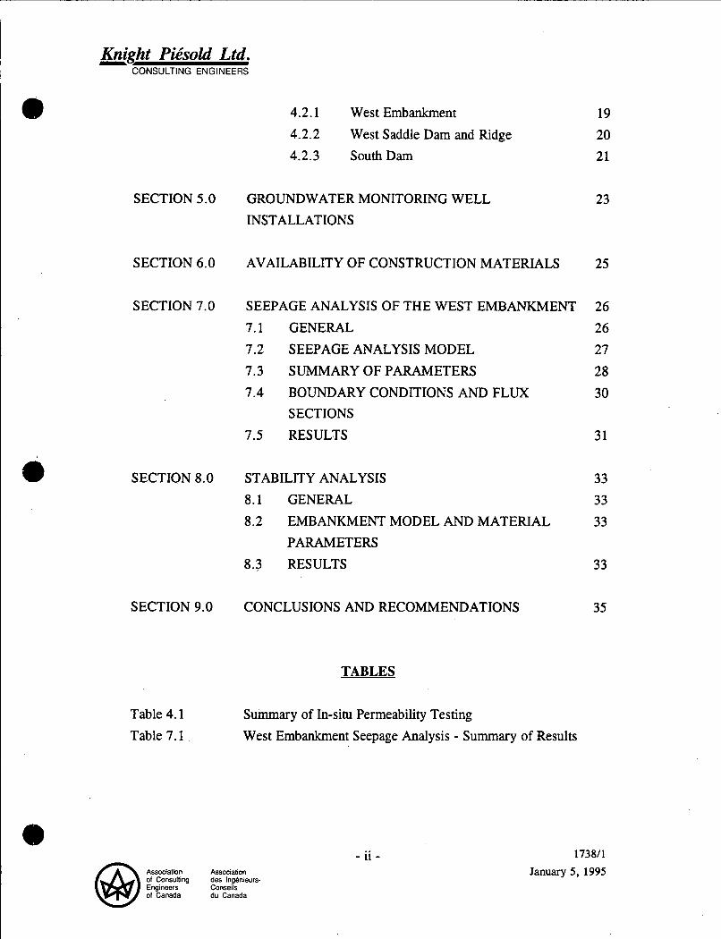
4.2.1 West Embankment 19 4.2.2 West Saddle Dam and Ridge 20 4.2.3 SouthDam 21
SECTION 5.0 GROUNDWATER MONITORING WELL INSTALLATIONS
23
SECTION 6.0 AVAILABILITY OF CONSTRUCTION MATERIALS 25
SECTION 7.0 SEEPAGE ANALYSIS OF THE WEST EMBANKMENT 26 7.1 GENERAL 26 7.2 SEEPAGE ANALYSIS MODEL 27 7.3 SUMMARY OF PARAMETERS 28 7.4 BOUNDARY CONDITIONS AND FLUX 30
SECTIONS 7.5 RESULTS 31
SECTION 8.0 STABILITY ANALYSIS 33 8.1 GENERAL 33 8.2 EMBANKMENT MODEL AND MATERIAL 33
8.3 RESULTS 33 PARAMETERS
SECTION 9.0 CONCLUSIONS AND RECOMMENDATIONS 35
Table 4.1 Table 7.1
Summary of In-situ Permeability Testing West Embankment Seepage Analysis - Summary of Results
Association Association of Consulting des Ingenieurs- Engineers Conseils of Canada du Canada
173811
January 5, 1995

- Knight Piksold Ltd. CONSULTING ENGINEERS
FIGURES
Figure 1.1 Project Location Map Figure 4.1 Figure 7.1
Figure 8.1
In-situ Packer Permeability Test Schematic Embankment Seepage Analysis - West Embankment Schematic Section Embankment Stability Analysis - West Embankment Schematic Section
DRAWINGS
1737.100 Rev. 1 1738.010 Rev.0 1738.020 Rev.0 Geological Sections
Overall Site Plan Overall Site Investigation Plan
APPENDICES
Appendix A Appendix B Appendix C Appendix D Appendix E
Test Hole Logs Exploratory Drilling - Bedrock Logs Point Load Test Results Results of In-Situ Permeability Testing Groundwater Monitoring Well Completion Details
... - l l 1 - Association Association of Consulting des Ingenieurs- Engineers Conseils of Canada du Canada
1738/1
January 5 , 1995

- Knight Piisold Ltd. CONSULTING ENGINEERS
TASEKO MINES LIMITED FISH LAKE PROJECT
1994 GEOTECHNICAL & HYDROGEOLOGICAL INVESTIGATIONS FOR PROPOSED TAILINGS STORAGE FACILITY
{REF. NO. 1738111
EXECUTIVE SUMMARY
The 1994 geotechnical field investigation program, carried out at the proposed tailings storage facility, comprised of a drilling program to investigate the geological and hydrogeological conditions along the west and south sides of the facility. The field investigation provided a considerable amount of data as follows:
e A thin covering of glacial till overlies bedrock along the proposed embankment alignments, and the till cover becomes thicker in topographic low areas and near Wasp Lake.
e Bedrock comprising basalt flows and Miocene Sediments were encountered near surface and had permeabilities ranging from to less than lo-’ cm/sec. The higher permeabilities were associated with the more fractured rock which was typically encountered near the till/bedrock contact. Average bedrock permeabilities ranged from lo4 to cm/sec.
e Surficial mapping identified basalt flows, Miocene Sediments and Kingsvale Sediments as were encountered in the tailings facility drillholes on the eastern slope above Big Onion Lake. These geological formations are continuous through the West Ridge which separates Big Onion Lake from the tailings storage facility.
e Finite element seepage analyses were performed to determine potential seepage flow rates through rock units under the proposed West Embankment. Calculated seepage flow rates ranged between 4.5 to 29.5
Usec (71 to 468 USgpm) depending on basalt permeabilities incorporated in 0 Association Association of Consulting de5 Ingenieurs- Engineers Conseils of Canada du Canada
- 1 - 1738/1,
January 5, 1995

- Knight Pibsold Ltd. CONSULTING ENGINEERS
d)
e-
a
the model as well as variable thicknesses of low permeability surficial glacial till. A seepage collection ditch and monitoring pond located down slope of the West Ridge and above Big Onion Lake are recommended to collect potential foundation seepage during operations. Water quality monitoring of collected seepage will also be required during operations and collected water may be treated and discharged or pumped back into the tailings impoundment.
0 Stability analyses, performed on the proposed final West Embankment, concluded that the embankment is stable under all possible loading conditions with high Factors of Safety.
0 Surficial mapping in the South Dam area revealed significant quantities of glacial till which will be suitable for borrow material during construction of the South Dam.
/h Association Association of Consulting des Ingbnieurs- Engineers Conseils of Canada du Canada
- 2 - 173811,
January 5 , 1995

- Knight Piisold Ltd. CONSULTING ENGINEERS
SECTION 1.0 - INTRODUCTION
1.1 PROJECT DESCRIPTION
The Fish Lake project site is located approximately 125 kilometres southwest of Williams Lake, British Columbia as shown on Figure 1.1. .
The Fish Lake project -iavolves open pit mining of an estimated 675 million tonnes of copper and gold ore which will be processed by selective flotation at a production rate of approximately 60,000 tonnes per day to produce a copper-gold concentrate. Tailings solids produced from the process will be stored within an engineered tailings storage facility located south of the proposed open pit. This facility is designed to provide permanent storage for up to 800 million tonnes of tailings.
The tailings storage facility will initially comprise a zoned Main Embankment constructed of overburden and waste rock from development of the open pit and will be built across the Fish Lake valley. The Main Embankment will be raised in stages using centreline construction methods when additional tailings storage is required. The West Embankment and West Saddle Dam will be constructed in future years using similar construction methods and materials as the Main Embankment. These two dams will be located on the west side of the storage facility along the topographic ridge which separates the Fish Creek drainage from Big Onion Lake and the Taseko River. The South Dam will be constructed in the final years of operation to provide additional tailings storage capacity and will retain the supernatant pond while preserving Wasp Lake and the adjacent valley. This dam will be constructed as a water-retaining structure from locally borrowed materials.
Seepage flows from the tailings storage facility will be intercepted and returned into the tailings area via seepage collection and recycle ponds located downstream of the West Embankment, West Saddle Dam and South Dam. . Underdrainage from the Main Embankment will be collected in the Open Pit/Waste Storage Recycle Sump and transferred to the mill for use as process water.
Association Association of Consulting des Ingenieurs- Engineers Conseils of Canada du Canada
- 3 - 1738/1,
January 5 , 1995

- Knight Pit!sold Ltd. CONSULTING ENGINEERS
The overall site plan of the Fish Lake project is shown on Drawing No. 1737.100.
The pre-feasibility design of the tailings storage facility is presented in Knight PiCsold Ltd. "Report on Site Geotechnical Considerations and Design of Tailings Storage Facility (Ref. No. 1737/1)", dated May, 1994.
Previous investigation work carried out by Knight PiCsold Ltd. on the Fish Lake project includes the following:
Initial overview in February 1991.
Site visit and reconnaissance followed by issuing of "Report on Preliminary Geotechnical Evaluation (Ref. No. 1731/1)", dated August, 1991.
Preliminary hydrogeological investigations at the proposed open pit with results presented in "Report on Preliminary Hydrogeological Investigations (Ref. No. 1732/2)", dated May, 1992.
Preliminary investigations in the proposed tailings impoundment site, summarized in "Report on Preliminary Geotechnical Investigations (Ref. No. 1733/1)", dated January, 1993.
Evaluation of rock mass characteristics and their influence on the bulk density in the Open Pit presented in "Report on Influence of Geotechnical Factors on Bulk Density (Ref. No. 1734/1)", dated March, 1993.
Analyses of available materials for construction of the tailings facility as presented in "Report on Materials for Embankment Construction and Concrete Aggregate (Ref. No. 1737/2)", dated February, 1994.
Design of the tailings storage facility presented in "Report on Site Geotechnical Considerations and Design of the Tailings Storage Facility (Ref. No. 1737/1)", dated May, 1994.
Association Association of Consulting des Ingenieurs- Engineers Conseils of Canada du Canada
- 4 - 173811, January 5, 1995

- Knight Piksold Ltd. CONSULTING ENGINEERS
(viii) Investigations within the Fish Lake deposit area for rock mass characterization and hydrogeological testing, presented in "Report on Open Pit Design (Ref. No. 1736/1)", dated March, 1994 and "Report on Open Pit Hydrogeological Investigations (Ref. No. 1736/2)", dated March, 1994.
1.2 SCOPE OF WORK
The tailings storage facility site investigation program was carried out by Knight PiCsold Ltd. and Quest Canada Inc. during July and August, 1994. The program objectives were to obtain geotechnical and hydrogeological information on the foundation conditions at the West Embankment, West Saddle Dam and South Dam sites.
The scope of work for the investigation program included the.following:
e
e
HQ-size coring of overburden and bedrock. Geotechnical logging of overburden and bedrock. In-situ wireline packer permeability testing, including rising and falling head testing, in overburden and bedrock. Installation of 51 mm (2 inch) diameter PVC groundwater monitoring wells in the completed drillholes. Development of groundwater monitoring wells for water quality sampling. Measurement of static groundwater levels in the completed wells.
Surficial mapping along the West Ridge between the West Embankment alignment and Big Onion Lake. Evaluation of the type and availability of borrow materials for construction of the South Dam.
This report forms part of the overall 1994 Knight PiCsold field program which included open pit hydrogeology and dewatering investigations, open pit oriented core drilling and plant and primary crusher site foundation investigations. The results of these programs are presented in "Report on 1994 Open Pit Investigations
Association Association of Consulting des Ingenieurs. Engineers Conseils 01 Canada du Canada
- 5 - 173811, January 5, 1995

- Knight Pibsold Ltd. CONSULTING ENGINEERS
(Ref. No. 1738/2)”, dated December, 1994. Specific design issues addressed in this report include:
e
0 embankment stability. seepage potential along West Embankment ridge during operation; and
Association Association of Consulting des Ingbnieurs- Engineers Conseils of Canada du Canada
- 6 - 173811,
January 5 , 1995

- Knight Piisold Ltd. CONSULTING ENGINEERS
SECTION 2.0 - FIELD WORK
A total of six geotechnical drill holes were drilled along the West Embankment, West Saddle Dam and South Dam alignments to investigate the foundation conditions along the western and southern limits of the proposed tailings storage facility. The holes were located by Taseko Mines Ltd. based on co-ordinates supplied by Knight PiCsold Ltd. The drillhole locations are shown on Drawing. 1738.010. Drilling was performed with a Val d’Or diamond drill rig, and site access was accomplished with an A-star helicopter supplied by Canadian Helicopters Ltd. Drilling commenced at the South Dam and progressively moved northwest along the West Ridge to the West Embankment.
Drillholes 94-148 and 94-150 were drilled along the downstream toe of the West Embankment. Drillhole 94-148 was located within the valley at the south end of the West Embankment and south of the watershed divide between Fish Lake and Big Onion Lake. The hole was advanced through a thick layer of glacial till overlying Miocene sediments and basalt flow lenses to a depth of 29.3 metres (96 feet) before being abandoned due to squeezing ground conditions which prevented further penetration of the drill rods. Drillhole 94-150 was located northwest of hole 94-148 at a higher elevation along the top of the ridge. This hole also encountered thin layers of glacial till, Miocene basalt and sediments and was advanced into the underlying Kingsvale Sediments. The hole was drilled to a depth of 38.4 metres (126 feet) prior to being abandoned due to fine sand caving in and binding the drill rods and core barrel in the hole.
Drillhole 94-147 was drilled in a narrow valley at the proposed West Saddle Dam site. The hole was advanced to a depth of 94.8 m (311 feet) and encountered a thin layer of glacial till overlying Miocene basalt flows and sediments.
Drillhole 94-144 was located on the ridge separating the West Saddle Dam from the South Dam site. The hole was advanced to a depth of 140.5 metres (461 feet) through a thin veneer of glacial till covering Miocene basalt flows and sediments and into the underlying Kingsvale Sediments. Geological and hydrogeological
I. Association Association of Consulting des Ingenieurs Engineers Conseils of Canada du Canada
- 7 - 173811,
January 5 , 1995

- Knight Piisold Ltd. CONSULTING ENGINEERS
information obtained from this hole was used to correlate the two adjacent dam site drillholes.
Drillholes 94-141 and 94-143 were located downstream of the South Dam alignment and north of Wasp Lake. These holes were drilled to investigate the hydrogeological conditions adjacent to Wasp Lake and provide foundation information for the South Dam. Holes 94-141 and 143 were advanced through a thin cover of glacial till into Miocene basalt flows to depths of 62.8 and 61.3 metres (206 and 201 feet), respectively.
In-situ permeability tests were performed in bedrock in each drillhole using packer permeability testing equipment to determine the coefficient of permeability of the foundation materials. The tests were carried out in descending stages as each hole was drilled, and each stage was defined as a test interval 10 metres (30 feet) long. The test intervals were isolated by a nitrogen inflated "through the bit" packer system and were successfully performed in holes 94-141, 143, 144, 147 and 150. Due to poorer ground conditions encountered in drillhole 94-148, the packer system could not be used and falling head tests were performed over extended test intervals.
After each drillhole was completed and all hydrogeologic testing performed, a monitoring well was installed to measure the groundwater elevation and to provide a' source for groundwater sampling.
Point load tests were performed on select bedrock samples from each drillhole to determine the Uniaxial Compressive Strength (UCS) of the rock types encountered. Samples from drillhole 94-144 were not selected for testing as this drillhole was not located at a potential dam location.
The test hole and bedrock logs for each drillhole are included in Appendices A and B, respectively. Point load test results, in-situ packer permeability test results and groundwater monitoring well completion details are presented in Appendices C, D and E, respectively.
Association Association of Consulting des Ingbnieurs- Engineers Conseils of Canada du Canada
- 8 - 173811,
January 5 , 1995

- Knight Piisold Ltd. CONSULTING ENGINEERS
SECTION 3.0 - GEOTECHNICAL RESULTS
3.1 GENERAL
Geotechnical information was collected from the West Embankment, West Saddle Dam and South Dam sites during the field investigation program. Detailed overburden and bedrock logging was carried out at the drill rig and consisted of the following items:
0 Depth and type of materials encountered. 0 Core Recovery and Rock Quality Designation (RQD).
colour, grain size, strength and weathering. Rock Mass Defects, including type, shape, roughness, spacing, frequency, orientation and type of infilling materials.
0 Lithology, including rock type, foliationhedding , hardness, structure,
0
The test hole logs included in Appendix A and detailed bedrock logs are included in Appendix B. Interpreted geologic sections are shown on Drawing 1738.020. The geotechnical investigation results are discussed in the sections which follow.
0.
3.2 WEST EMBANKMENT
Drillholes 94-148 and 150 encountered glacial till of varying thickness overlying bedrock. Hole 94-148, located at the bottom of a shallow valley, encountered a thick layer of stiff, brown till and a softer grey-coloured till comprising silty clay to sandy silt and gravel with some cobbles to a depth of 9.3 metres (32 feet). A thinner veneer of coarse-grained, redhrown till was encountered in hole 94-150 to a depth of 2.7 metres (9 feet).
Below the glacial till, both drillholes encountered sequences of basalt and Miocene sediments. Hole 94-148 encountered a thin layer of siltstone overlying conglomerate and basalt. The siltstone comprised weakly indurated, brownish grey silt to fine sand, soft to very soft in places, becoming increasingly coarser and more friable with depth. The conglomerate comprised weak to strongly indurated heterolithic
Association Association of Consulting des Ingbnieurs- Engineers Conseils of Canada du Canada
- 9 - 173811,
January 5 , 1995

- Knight Piisold Ltd. CONSULTING ENGINEERS
gravels and cobbles in a brown sandy clay to clayey sand matrix. Typically only loose gravel and cobbles were recovered during drilling as the drill fluids washed the fines away. The conglomerate was typically very weak and extremely fractured with low to negligible RQD. A thin layer of fine grained, dark grey basalt was encountered at depth within the conglomerate. The hole was cored to a depth of 29.3 metres (96 feet) before being abandoned due to fines washing out from the siltstone and conglomerate formations and seizing the drill rods.
Beneath the glacial till, drillhole 94-150 encountered dark grey to greenish grey coloured basalt flows which form the West Ridge. The basalt flows comprised alternating sequences of .fine grained, generally massive to vesicular and vuggy rock. The massive sequences were moderately strong and more competent than the vesicular zones. The top 5.2 metres (17 feet) of the basalt, located directly below the tillhedrock contact, was highly fractured with negligible RQD and exhibited limonite stained zones throughout. Rock quality increased from fair to good with depth, with occasional fractured zones of very poor rock. Traces of dark green, weak and brittle chloritized clay or mudstone were found within some vesicles and vugs and occasionally within a matrix of vesicular basalt. This mudstone appeared waxy and may represent an ancient weathering horizon within the basalt which was heated and crystalized during emplacement of the upper basalt flow.
The green coloured Miocene conglomerate encountered in hole 94-148 was also intersected in hole 94-150 below the basalt flows to a depth of 31.6 metres (104 feet). More competent sections of conglomerate with moderate to well indurated zones of poorly sorted sands and gravels were encountered at depth. Kingsvale Sediments were encountered at 31.6 metres (104 feet) depth and comprised black argillite and Cretaceous conglomerate. These sediments were typically weak to moderately strong with good to excellent core recovery but poor RQD. The dark grey argillite was highly jointed and sheared parallel to the bedding planes. The older Cretaceous conglomerate exhibited fewer joints compared to the younger, overlying conglomerate and had moderate RQD.
Association Association of Consulting des Ingbnieurs. Engineers Conseils of Canada du Canada
- 10- 173811,
January 5 . 1995

- Knight Piisold Ltd. CONSULTING ENGINEERS
4D
a
3.3 WEST SADDLE DAM AND RIDGE
Drillholes 94-144 and 94-147 were drilled to investigate the geotechnical characteristics of the foundation materials of the ridge and West Saddle Dam, respectively.
Glacial till, comprising brown sandy clay with some gravel and cobbles, was encountered as a thin layer (1.8 metres) on top of the ridge in drillhole 94-144 and as a thicker layer (4.9 metres) in the base of the saddle valley in drillhole 94-147. Beneath the till, sequences of Miocene basalt flows and sediments were encountered to depths of 124.0 and 94.8 metres (407 and 3 1 1 feet) in holes 94-144 and 147, respectively. below the younger Miocene sediments in drillhole 94-144.
Kingsvale Sediments, comprising argillite, were also encountered
The basalt tlows comprised dark greedgrey coloured rock with alternating sequences of vesicular and vuggy zones and fine-grained massive zones. Basalt encountered in the upper portion of hole 94-144 ranged from poor to good quality, moderately fractured rock with moderate RQD, and increased to extremely competent, sparsely fractured rock with high RQD at depth. Basalt encountered in drillhole 94-147 was typically very competent with few fractures and high RQD throughout, and corresponded with the competent basalt zones identified in hole 94- 144 at similar elevations.
Miocene sediments were encountered beneath the basalt flows in both drillholes. The sediments comprised siltstone, sandstone, claystone, conglomerate and some gravel lenses. Poor core recovery, high defect concentrations and very low RQD values were typical characteristics of these sedimentary layers. The siltstone and sandstone were friable and the fines were generally washed away during drilling. In contrast, the claystone was more competent with moderate to high core recovery and RQD and exhibited very few joints or other defects. The conglomerate comprised consolidated gravel and cobbles in a weak sandy matrix which generally washed away during drilling.
- 1 1 - Association Association of Consulting des Ingbnieurs- Engineers Conseils of Canada du Canada
173811,
January 5 , 1995

- Knight Piisold Ltd. CONSULTING ENGINEERS
The Kingsvale Sediments comprised argillite and were encountered below the Miocene sediments at great depth in drillhole 94-144. The argillite varied from slightly to highly fractured, low to moderate RQD rock with some slickensides on joint surfaces and calcite infilling throughout.
3.4 SOUTHDAM
Drillholes 94-141 and 94-143, located on the downstream side of the proposed South Dam alignment, encountered a thin layer of glacial till overlying dark grey coloured basalt flows. The till comprised dark brownlgrey, dense sandy clay with some gravel and cobbles to depths of 5.8 and 3.1 metres (19 and 10 feet), respectively. The basalt comprised alternating sequences of moderate to strongly vesicular and vuggy zones as well as more competent, fine-grained massive zones. Characteristic red-grey and brown discolourations were evident in the weathered basalt near surface and at local intervals throughout. The basalt was moderately fractured with excellent core recovery and poor to very good RQD. RQD varied depending upon the vesicular nature of the rock and the depth within the formation, and the vesicular and vuggy sections were typically very fractured with low RQD. Occasional thin seams of indurated, weak chloritized clay or mudstone were also encountered within the basalt flows, representing a possible ancient weathering horizon. Seams up to 10 cm thick were observed, and some exhibited slickensided fracture surfaces when broken. This horizon was also observed in the basalt flows encountered in the other drillholes.
Interbedded, thin layers of well indurated but friable grey-greenbrown siltstone, fine sandstone and conglomerate were also encountered at depth in hole 94-141.
3.5 ' SURFICIAL MAPPING AND GEOLOGICAL INTERPRETATION
The foundation investigation for the West Embankment included two days of surficial geological mapping along the West Ridge which divides the proposed tailings storage facility from Big Onion Lake. The mapping results were combined with information obtained from previous work, the 1994 tailings storage facility
Association Association of Consulting des Inghieurs. Engineers Conseils of Canada du Canada
- 12- 173811,
January 5 , 1995
- Knight Piksold Ltd. CONSULTING ENGINEERS
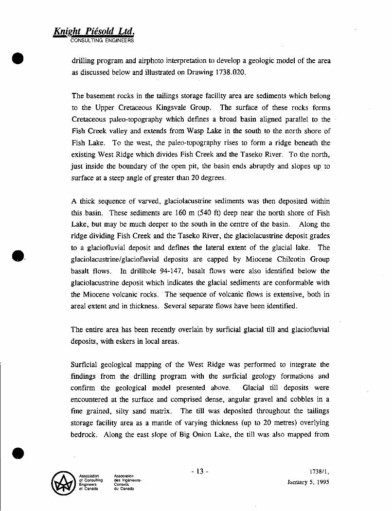
drilling program and airphoto interpretation to develop a geologic model of the area as discussed below and illustrated on Drawing 1738.020.
The basement rocks in the tailings storage facility area are sediments which belong to the Upper Cretaceous Kingsvale Group. The surface of these rocks forms Cretaceous paleo-topography which defines a broad basin aligned parallel to the Fish Creek valley and extends from Wasp Lake in the south to the north shore of Fish Lake. To the west, the palso-topography rises to form a ridge beneath the existing West Ridge which divides Fish Creek and the Taseko River. To the north, just inside the boundary of the open pit, the basin ends abruptly and slopes up to surface at a steep angle of greater than 20 degrees.
A thick sequence of varved, glaciolacustrine sediments was then deposited within this basin. These sediments are 160 m (540 ft) deep near the north shore of Fish Lake, but may be much deeper to the south in the centre of the basin. Along the ridge dividing Fish Creek and the Taseko River, the glaciolacustrine deposit grades to a glaciofluvial deposit and defines the lateral extent of the glacial lake. The glaciolacustrine/glaciofluvial deposits are capped by Miocene Chilcotin Group basalt flows. In drillhole 94-147, basalt flows were also identified below the glaciolacustrine deposit which indicates the glacial sediments are conformable with the Miocene volcanic rocks. The sequence of volcanic flows is extensive, both in areal extent and in thickness, Several separate flows have been identified.
The entire area has been recently overlain by surficial glacial till and glaciofluvial deposits, with eskers in local areas.
Surficial geological mapping of the West Ridge was performed to integrate the findings from the drilling program with the surficial geology formations and confirm the geological model presented above. Glacial till deposits were encountered at the surface and comprised dense, angular gravel and cobbles in a fine grained, silty sand matrix. The till was deposited throughout the tailings storage facility area as a mantle of varying thickness (up to 20 metres) overlying bedrock. Along the east slope of Big Onion Lake, the till was also mapped from
Association Association of Consulting des Ingbnieurs- Engineers Conseils of Canada du Canada
- 13 - 1738/1,
January 5 , 1995

- Knight Pibsold Ltd. CONSULTING ENGINEERS
the lakeshore up to elevation 1375 metres where bedrock outcrops were observed up to elevation 1610 metres.
Two distinct Miocene basalt flows were mapped in outcrop from elevation 1505 to 1610 metres. The lower flow, ranging from at least elevation 1505 to 1515 metres, comprised massive, weakly vesiculated, dark grey, fresh basalt with columnar joints spaced at 200 mm. The upper flow, which outcropped from 1540 to 1550 metre elevation, comprised massive, moderately well vesiculated, maroon to dark brown/grey coloured weathered basalt with columnar joints spaced at 450 mm. The contact between the flows was not seen on surface, however, based on the topography and the orientation of columnar joints, the contact is inferred to be sub- horizontal.
On a bedrock knoll approximately 2.5 kilometres east of Big Onion Lake, a sequence of basalt flows overlying the basalt flows described above was encountered up to the local topographic high point of 1610 metres.
Beneath the columnar jointed basalt, additional basalt flows were encountered in outcrop. These flows were observed to overlie argillaceous siltstone (Kingsvale Sediments) between elevation 1495 and 1505 metres, although the geologic contact was concealed beneath the talus-covered slope. A 13 metre thick layer of weakly indurated Miocene conglomerate was encountered in drillhole 94- 150 between these basalt and argillaceous siltstone units. Although this conglomerate layer was not seen in outcrop, well rounded gravel and cobbles were found in float on the slope below the basalt, and it is inferred that the conglomerate exists between the basalt and argillaceous siltstone outcrops on the slope but is weaker and has been eroded away.
Additional Miocene sediments were encountered near surface in drillhole 94- 147 along the West Ridge and at the West Saddle Dam site. These sediments comprised similar conglomerate as encountered in hole 94-150, as well as interbedded lacustrine clay/silt/fine sand and weakly consolidated sand and gravel layers. A thin layer of Miocene basalt was encountered near the base of these sedimentary
Association Association of Consulting des Ingenieurs- Engineers Conseils of Canada du Canada
- 1 4 - 173811,
January 5 . 1995

- Knight Pibsold Ltd. CONSULTING ENGINEERS
e
layers, indicating the sediments are the younger Miocene sediments and not the older Cretaceous Kingsvale Sediments.
Cretaceous Kingsvale Sediments comprising argillaceous siltstone and pebble conglomerate were encountered in outcrop beneath the Miocene basalt and sediments. The fine grained, dark grey argillaceous siltstone overlies the pebble conglomerate between elevation 1470 to 1495 metres. The siltstone was well indurated and strongly jointed with weak foliation and relic bedding evident. Orientations of 295"/70" and 025"/80" (strikeldip) were measured on the foliation and bedding planes. Joints were parallel to these planes, and an average joint spacing of 10 to 15 mm resulted in a crumbly, weak, poorly exposed rock mass.
A well indurated, weakly hornfelsed and slightly deformed pebble conglomerate was encountered between elevation 1375 to 1470 metres. The conglomerate contained densely packed, well rounded pebbles in a fine siltstone matrix, and zones of elliptical pebbles were evident suggesting the rock had undergone some degree of tectonic deformation. Mapped outcrops were poorly jointed, and the rock was typically hard, massive and competent.
3.6 LABORATORY TESTING
3.6.1 Overburden Material
One representative sample of glacial till was selected for laboratory testing from drillhole 94-148 (8.5 to 8.8 metres depth). This sample was typical of the overburden materials found near surface in each of the drillholes. The results of the testwork are as follows:
0
Grain size distribution: 27% gravel 34% sand 28% silt 11 % clay
Natural moisture content = 4.5 %
- 15 - Association des Inghieurs- Conseils du Canada
173811,
January 5 , 1995

- Knight Piisold Ltd. CONSULTING ENGINEERS
0 Specific gravity = 2.75 0
0
Void Ratio, e = 0.24 In-situ Dry Density = 2.22 t/m3
0 Triaxial Permeability on cored sample, k = 4 x lo-’ c d s e c
This sample of brown, silty gravelly sand with some clay was very dense and exhibited a very low permeability. The sample is typically two to three orders of magnitude less permeable than the underlying basalt flows.
3.6.2 Point Load Testing of Bedrock
Random samples from the West Embankment, West Saddle Dam and South Dam drillholes were taken for point load testing to determine the Uniaxial Compressive Strength (UCS) of the foundation materials. In the point load test, compressive loads are applied through hardened conical points to diametrically or axially opposite sides of a core specimen until failure occurs. A good correlation exists between the Point Load Strength Index (Is), calculated as the failure load divided by the square of the core diameter, and the Uniaxial Compressive Strength (a,) of the material:
a, = K * Is
where K = 22 for 45 mm (NQ3) and 25 for 63.5 mm (HQ) diameter core.
A total of 43 point load tests were performed in the field on bedrock samples taken from the upper 50 metres of each hole. The majority of samples tested were basalt (33, with samples of sandstone (l), conglomerate (6) and argillite (1) tested where possible. The results show the uniaxial compressive strength of the basalt flows ranged from very weak to very strong and depended upon the vesicular or massive nature of rock. The frequency distribution of uniaxial compressive strengths for the basalt flows is given below:
Association Association of Consulting des Ingenieurs. Engineers Conseils 01 Canada du Canada
- 16- 1738/1,
January 5 , 1995

- Knight Pibsold Ltd. CONSULTING ENGINEERS
a The sandstone sample from hole 94-141 was weak. The conglomerate samples from holes 94-148 and 150 were strong to very strong and very weak to extremely weak, respectively. The argillite sample from hole 94-150 was very weak.
The results of the point load testing are included in Appendix C.
- 17- 173811,
January 5, 1995

- Knight Pibsold Ltd. CONSULTING ENGINEERS
SECTION 4.0 - HYDROGEOLOGICAL RESULTS
4.1 GENERAL
In-situ packer testing was performed in the overburden and bedrock to determine the permeability characteristics of each material. Falling head and rising head permeability tests were carried out when packer testing could not be performed.
4.2 IN-SITU PERMEABILITY TESTING
In-situ permeability testing was carried out during drilling of each hole using an HQ wireline double packer system. The general procedure for each test was as follows:
0 Core with HQ to depth required to define the test interval.
Insert the HQ wireline packer system down the drill rods and seat on the
0 Pull back the drill rods to expose the test interval.
drill bit. Inflate the packers to isolate the test interval.
Fill the test interval and drill rods with water and seal. Perform the permeability test by pumping water into the test interval at a designated pressure and record the volume of water that flows into the formation.
0
0
0
0
Each packer test comprised applying five pressure stages to the formation and measuring the corresponding flows into the formation at each stage. In the first half of the test, the pressure was increased through three stages, to a maximum pressure. In the second half of the test, the pressure was decreased in two stages, through the same pressures applied in the risins portion of the test.
A schematic figure showing the general arrangement of the test is shown on Figure 4.1. Included on this figure is a typical plot of the test results showing the relationship between the head applied to the formation and the measured flow for all five stages. In an idealized plot, the rising and falling limbs are linear from the
a Association Association of Consulting des Ingbnieurs- Engineers Conseils of Canada du Canada
- 18- 1738/1,
January 5 . 1995

- Knight Piisold Ltd. CONSULTING ENGINEERS
Rock Type
Till/Siltstone T ill/S ilts tone
origin, and are superimposed over one and other. In vertical boreholes this test provides information on the horizontal permeability.
Packer tests were performed in 10 metre (30 foot) intervals, unless ground or drilling conditions proved unsuitable for this approach. In such instances, falling head permeability tests were utilized. For artesian conditions, rising head tests were carried out.
The test intervals and corresponding permeability results for each drillhole are shown on Drawing No. 1738.020. A summary of the results is given on Table 4.1, and details of the results, which include plots of head versus flow for each in-situ
Permeability Bedrock Conditions (cm/sec) 8 x No core recovery 1 Poor recovery/RQD
packer
4.2.1
test interval, are included in Appendix D.
West Embankment
Falling head tests and in-situ packer permeability tests were performed in drillholes 94-148 and 150, respectively.
Two falling head tests were carried out in the glacial till and Miocene
sediments (siltstone, conglomerate) in drillhole 94-148. Permeability results are as follows:
Poor core recovery and RQD was a result of the fines washing away during drilling and are not representative of the overall rock quality.
Five packer permeability tests were carried out in the Miocene basalt flows and sediments (conglomerate) and in the Kingsvale Sediments (argillite and conglomerate) in drillhole 94-150. The test results for each rock type are summarized as follows:
- 1 9 - Association Association of Consulting des Inghieurs- Engineers Conseils of Canada du Canada
1738/1,
January 5. 1995

- Knight Pit%old Ltd. CONSULTING ENGINEERS
Rock Type
Basalt Miocene Sediments Kingsvale Sediments
Permeability Range Bedrock Conditions (cm/sec) 1 Moderately broken, moderate RQD
2 x loe6 to 1 x lo-’ Low core recovery, poor RQD 2 io-’ Very broken, low to moderate
RQD
A 50 percent loss of return water was observed in the basalt at 13.4 metres
Rock Type
Basalt
Miocene Sediments Kingsvale Sediments
(44 feet) depth during drilling, and both packer tests were carried out within this zone. Although high permeabilities of 1 x cm/sec were calculated for each test interval, these test results are indicative of the local high permeability zone and are not representative of the entire basalt rock unit.
Permeability Range Bedrock Conditions (cm/sec)
9 x lo-’ to 3 x lo4
8 x 10‘’ to 1 x
Very fractured and moderate RQD to few fractures and high RQD
Poor recovery/RQD 1 x Very fractured/low RQD
Low RQD values for the Miocene sediments are a result of washing the fine-grained matrix during drilling and are therefore not representative of the in-situ rock quality.
4.2.2 West Saddle Dam and Ridge
Packer permeability tests were performed in the Miocene basalt and sediments (sandstone, conglomerate and lacustrine claystone) and in the Kingsvale Sediment (argillite) layers encountered in drillholes 94- 144 and 147. The test results for each formation are summarized as follows:
- 20 - Association Association of Consulting des Inghieurs- Engineers Conseils of Canada du Canada
173811, January 5 , 1995

- Knight Piisold Ltd.
Basalt
Miocene Sediments
CONSULTING ENGINEERS
(cm/sec) 1 x loe8 to 8 x Moderate to few fractures,
moderate to high RQD 3 x to 2 x Variable core recovery and RQD
I '
Drillhole 94-147 Rock Type I Permeability Range I Bedrock Conditions
The basalt was the most competent rock encountered in both drillholes. Higher permeabilities were typically encountered near surface and adjacent to sedimentary layer contacts, whereas lower permeabilities were predominant throughout the majority of the rock unit.
Permeability results for the Miocene sediments varied depending upon depth and not core recovery or RQD. The more permeable sediments were encountered in drillhole 94-147 between 50 and 95 metres depth, whereas the less permeable sediments were encountered in hole 94-144 at 113 to 124
metres depth. The Kingsvale Sediments were as impermeable as the overlying sediments encountered in hole 94- 144.
A falling head test was performed in hole 94-144 in the completed groundwater monitoring well to determine the permeability of the siltstone/ sandstone layer at 57 metres depth. The test interval was defined by the monitoring well's filter sand zone from 48.8 to 70.3 metres depth and bounded by the upper grout plug and lower bentonite seal, respectively. A
permeability of 8 x cm/sec was measured from the falling head test, and this corresponded with the packer permeability test result over the same test interval. The permeability calculation using the Hvorslev method is included in Appendix D.
4.2.3 South Dam
Artesian conditions were encountered at the South Dam site in drillhole 94- 141 at depth below 7.9 metres (26 feet). One packer test was carried out between 7.9 and 17.1 metres (26 to 56 feet) and rising head tests were then
Associalion Association of Consulting des Ingbnieurs- Engineers Conseils 01 Canada du Canada
- 21 - 1738/1,
January 5, 1995

- Knight Piisold Ltd. CONSULTING ENGINEERS
Material Type
Upper Basalt Miocene Sediments
Lower Basalt
performed through the remainder of the hole. The permeability test results are summarized as follows:
Permeability Artesian Bedrock Conditions Range Flow Rate
3 io-’ 0.25 Very fractured, low RQD 2 2.0 Poor core recovery
(cm/s) (t/min)
2 x to 1 x 0.2 to 1 . 1 Moderately fractured, moderate to high RQD
II RockType
Prior to each permeability test, the artesian flow rate was measured out the top of the casing as specified in the above table. An artesian pressure head of 3.6 to 7.0 metres (5 to 10 psi) was also measured with the packer system in the first test interval.
Permeability Range Bedrock Conditions II (cm/sec)
Artesian conditions were not encountered in drillhole 94-143. A total of six in-situ packer permeability tests were carried out within the basalt, and the test results are summarized as follows:
Upper Basalt Lower Basalt /I /I 1 x lo4 Very fractured, low RQD
2 x to 1 x lo-’ Moderately fractured, moderate to high RQD
The upper 25 metres of the hole was found to be more permeable than the lower portion of the hole, and this corresponded with the more fractured and weathered rock encountered near the surface. Moderate to high RQD corresponded with lower permeability results in the remainder of the drillhole below 25 metres depth.
a Association Association of Consulting des Ingenieurs- Engineers Conseils of Canada du Canada
- 22 - 1738/1,
January 5, 1995

- Knight Piisold Ltd. CONSULTING ENGINEERS
0 SECTION 5.0 - GROUNDWATER hlONITORING MTLL INSTALLATIONS
Groundwater monitoring wells were installed in each geotechnical drillhole at the West Embankment, West Saddle Dam, West Ridge and South Dam sites for the on- going baseline groundwater quality sampling program.
Each well consisted of a threaded, 3.05 metre (10 foot) long, slotted Schedule 40 PVC screen placed at the bottom of the drillhole and solid riser pipe attachments extending to the surface. A mechanical Van Ruth plug was used in holes where the screen was placed well above the bottom of the hole. Each screen was surrounded by a permeable filter sand zone which was confined by an upper and lower bentonite seal. The completion zone is defined as the length of hole between these two seals. The remainder of the hole, above the upper bentonite seal, was grouted to surface to prevent inflow of surface water. A lockable steel casing protects the top of each well at the surface. Groundwater monitoring well completion details are included in Appendix E, and the completion zone depths are summarized as follows:
11 Hole No. I Completion Zone Depths (from ground level) I( 11 94-141 I 26.6 to 33.2 metres (87 to 109 feet) ll I/ 94-143 I 27.0 to 34.2 metres (88 to 112 feet) 11 11 94-144 I 48.8 to 70.3 metres (160 to 231 feet) I( I/ 94-147 1 47.7 to 58.2 metres (156 to 191 feet) (1
II 11 94-148 I 1.0 to 26.4 metres (3 to 87 feet)
11 94-150 I 17.1 to 31.3 metres (56 to 103 feet) 11 Each well was installed while the drill rig remained over the hole. In general, the drill rods were pulled out of the hole prior to the installation of the PVC pipes, except in cases when the hole was likely to collapse. In these cases, the lower
Association Association of Consulting des Ingenieurs- Engineers Conseils of Canada du Canada
- 23 - 173811,
January 5, 1995

- Knight Piksold Ltd. CONSULTING ENGINEERS
bentonite seal, filter sand and PVC pipes were placed through the drill bit before the rods were withdrawn.
Difficulties were encountered during installation of some of the monitoring wells. The upper bentonite seal could not be installed above the filter sand zone in hole 94- 144 due to the hole becoming partially blocked with sloughing material when the drill rods were withdrawn. A layer of finer-grained sand was placed on top of the filter sand zone prior to grouting the hole to ensure the filter zone would not be contaminated by the upper grout seal.
In drillhole 94-148, overburden immediately collapsed around the monitoring well pipe after the drill rods were withdrawn. The remaining voids around the well were filled with filter sand and an upper bentonite seal was installed near surface. A thin grout cap was placed above the bentonite.
Developing the groundwater monitoring wells and measuring the static water levels will be performed by Taseko Mines Limited at a future date.
Association Association of Consulting des Ingenieurs Engineers Conseils of Canada du Canada
- 24 -
\
173811,
January 5 , 1995

- Knight Piksold Ltd. CONSULTING ENGINEERS
0 SECTION 6.0 - AVAILABILITY OF CONSTRUCTION MATERIALS
Overburden materials obtained from pre-production and on-going development of the open pit will be used as construction materials for the Main Embankment, West Embankment and West Saddle Dam. These materials were investigated and tested during the 1993 open pit investigation program, and the results and construction material requirements are presented in the Knight Piesold Ltd. "Report on Materials for Embankment Construction and Concrete Aggregate (Ref. No. 1737/2)", dated February 10, 1994.
During the 1994 tailings storage facility investigation program, the availability of construction materials for the South Dam was investigated. Initial observations in the South Dam area of moderate to dense tree cover on gentle, rolling topography and frequent swampy areas around Wasp Lake indicated the presence of low permeability surficial materials. Results from the drilling program and site reconnaissance of the area close to the South Dam show the surficial geology of the area is characterized by a dense layer of glacial till overlying basalt flows. Drillholes 94-141 and 94-143, located at the South Dam site, encountered dense, dark brown sandy silty clay till with gravel and cobbles as well as grey, clayey gravel and cobble till to depths of 5.8 and 3.1 metres (19 and 10 feet), respectively.
The glacial till is pervasive throughout the area and, based upon initial calculations, is available in quantities required for construction of the South Dam. Borrow areas located within the limits of the tailings storage facility will be preferentially selected over other areas in order to reduce surface disturbance around Wasp Lake and in the adjacent valley.
Association Association of Consulting des Ingenieurs- Engineers Conseils of Canada du Canada
- 25 - 1738/1,
January 5 , 1995

- Knight Piisold Ltd. CONSULTING ENGINEERS
8 SECTION 7.0 - SEEPAGE ANALYSIS
7.1 GENERAL
Seepage through the West Ridge is an important hydrogeological factor in the design of the tailings storage facility. The seepage flow rate and direction of seepage migration from the tailings facility into Big Onion Lake and the adjacent Taseko River Valley are of significant importance to the project.
During the initial years of operation of the tailings storage facility, natural hydraulic confinement due to existing groundwater levels along the topographic ridge of the Fish Creek Valley will restrict tailings solution from seeping through the West Ridge. The Fish Creek Valley is continually being recharged by groundwater which originates from higher elevations and flows down gradient to the bottom of the valley. Water levels measured in existing groundwater monitoring wells along the West Ridge and at the Main Embankment confirm the water table typically follows topography. Initially, the hydrostatic head of the tailings solution will not be great enough to overcome the influence of the regional groundwater recharging effects, and all seepage flow will therefore occur at the base of the valley through the foundation of the Main Embankment. A small amount of seepage is anticipated beneath the Main Embankment as a thick layer of low permeability glacial till blankets the valley. The abundance of lakes and ponds confirms the low permeability properties of the till. Any seepage that permeates through the till layer and into the underlying Miocene basalt flows and sediments will be transported down gradient and will be intercepted by the Open Pit groundwater depressurization wells. These wells will pump the seepage into the Open Pit/Waste Storage Recycle Sump where the water will be transferred to the mill for use in the milling process.
Construction of the West Embankment along the West Ridge will commence in Year 2. By the beginning of Year 4, the tailings solution will encroach upon the lowest point in the West Ridge and begin to overcome the natural hydraulic confinement and cause seepage to occur. Initially, seepage flows will be minimal as a thick layer of low permeability till blankets the bottom of the saddle. In addition, the length of the West Embankment and the corresponding lateral extent of the
Association Association of Consulting des Ingbnieurs- Engineers Conseils of Canada du Canada
- 26 - 1738/1,
January 5 , 1995

- Knight Piisold Ltd. CONSULTING ENGINEERS
seepage path are very narrow at this time. By Year 10, seepage is expected to increase through the foundation of the West Embankment as tailings will cover the majority of the 2400 metre long portion of the West Ridge.
Foundation seepage in later years will be controlled by the horizontally deposited Miocene basalt flows and sedimentary layers that extend through the West Ridge and outcrop above Big Onion Lake. A thin blanket of glacial till covers these formations and acts as a barrier against seepage flow. The till deposit is typically thin, and airphoto analyses have revealed the till to be potentially discontinuous on steep slopes and in local areas along the West Ridge. The basalt and sedimentary layers are typically more permeable than the glacial till, and seepage is expected to be transmitted horizontally through these rock formations. Although basalt flows encountered throughout most of the tailings facility were relatively impermeable, localized fractured zones with high permeabilities were found in the West Ridge which may significantly contribute to seepage flow. The majority of flow is expected to be transmitted through conglomerate and sandstone formations.
Detailed information from the geotechnical investigations has been used to construct a groundwater seepage model of the tailings facility to estimate seepage flow through the West Embankment and foundation. Details of the analysis method, assumptions and results are discussed in the following text.
7.2 SEEPAGE ANALYSIS MODEL
A seepage model was performed using the finite element compu S E E P N . Two different foundation conditions were considered:
:r program
CASE I) CASE 11)
Thin till cover overlying a thick layer of basalt. Thick till cover overlying Miocene Sediments.
Four models for Case I and two models for Case I1 were examined. Figure 7.1 and Table 7.1 summarize the material parameters and results for each model. These results were then applied proportionately to the localized geological conditions along
Association Association of Consulting des Ingenieurs- Engineers Conseils of Canada du Canada
- 27 - 173811, January 5 . 1995

- Knight Piisold Ltd. CONSULTING ENGINEERS
the length of the embankment to determine the total amount of seepage exiting the facility.
Several different foundation conditions were included to represent the complex geology of the West Ridge. The modelled geological conditions are summarized as follows:
0
0
0
Thin glacial till and low permeability basalt on the south end of the ridge. Thick glacial till and low permeability sediments in the base of the saddle. No glacial till and low permeability basalt and sediments in local areas (approximately 10%) along the north end of the ridge. Thin glacial till and low permeability basalt and sediments along the north end of the ridge. Thin glacial till, high permeability basalt and low permeability sediments along the north end of the ridge.
0
0
These analyses were extrapolated over the length of the West Ridge in order to calculate the total seepage flow through the West Embankment foundation.
The seepage model includes the zoned embankment and adjacent tailings, as shown on Figure 7.1. A tailings beach of about 60 m width has been included adjacent to the embankment. The longitudinal drain along the upstream toe and the seepage collection ditch at the downstream toe were also incorporated into the model.
The seepage analysis was carried out based on the following assumptions:
0 Steady-state flow conditions. Homogeneous, isotropic flow conditions.
7.3 SUMMARY OF PARAMETERS
Saturated and unsaturated hydraulic conductivities were determined for each material in the embankment and foundation zones. Typically, a saturated material has a hydraulic conductivity several orders of magnitude greater than a similar
a Association Association of Consulting des Ingenieurs- Engineers Conseils of Canada du Canada
- 28 - 1738/1.
January 5, 1995

- Knight Piksold Ltd. CONSULTING ENGINEERS
unsaturated material. In assigning hydraulic conductivity values for the seepage analysis, it was assumed that partially saturated clays and fines will have a hydraulic conductivity that is two orders of magnitude lower and partially saturated sands and gravels will be three orders of magnitude lower than similar saturated materials. Hydraulic conductivities of materials that were a combination of all soil types were adjusted accordingly. Conductivity values referenced in this section pertain to saturated flow conditions.
Hydraulic conductivity values for the tailings mass, embankment and foundation were determined as follows:
0 The tailings mass was sub-divided into three zones of equal thickness and decreasing hydraulic conductivity to more accurately model the consolidated, less permeable tailings with depth. In one analysis, the entire tailings mass was assigned a uniform permeability of 3 x cm/s to model the tailings during the early years of operation when very little consolidation has occurred.
0 Hydraulic conductivity values for the various zones of the embankment were estimated based upon typical values for similar construction materials.
0 Hydraulic conductivities for the Miocene Sediments and basalt flows in the embankment foundation were obtained from the in-situ packer permeability test results in drillholes 94-148 and 94-150. The hydraulic conductivity or glacial till was determined from laboratory permeability testing.
In Case I, a highly permeable layer of basalt was assumed to exist near surface and underlie the entire embankment section. In Case 11, the embankment was founded on several layers of less permeable Miocene Sediments and a basalt seam. Figure 7.1 illustrates the differences in the foundation profiles of these two cases and presents a summary of all material parameters used for the analysis.
Association Association of Consulting des Ingbnieurs- Engineers .Conseils of Canada du Canada
- 29 - 1738/1,
January 5 , 1995

- Knight Piksold Ltd. . CONSULTING ENGINEERS
7.4 BOUNDARY CONDITIONS AND FLUX SECTIONS
Boundary conditions were imposed on the modelled sections to more accurately represent hydrogeologic conditions in the field. These conditions are summarized as follows:
e A no-flow boundary condition was assigned to the nodes along the left side of the model.
e A total head boundary was imposed at the tailings surface to model a supernatant pond.
e The upstream embankment toe drain was modelled by applying a no-head condition at that location.
e The seepage recovery wells, located downstream of the embankment, were modelled by assigning head values to a vertical line of nodes. The tip of the well was assumed to be at the base of the basalt layer and the water level in the well was set at the top of this layer.
e A hydrostatic pore pressure profile with the water table 5 metres below the ground surface was assigned to the right boundary of the model.
Flux sections were included in the model to estimate seepage flow across the various geological units, as well as the engineered components. Four locations, in particular, were examined closely:
e Seepage inflow to the upstream toe drain was computed.
e Seepage flow into the embankment drainage system downstream of the core zone was computed from the difference of flow rates across two flux sections. One section was made just upstream of the toe and the other was made just downstream of the toe. The difference represents the amount of seepage collected. 0
Association Association of Consulting des Ingenieurs- Engineers Conseils of Canada du Canada
- 30 - 1738/1,
January 5 , 1995

- Knight Piisold Ltd. CONSULTING ENGINEERS
0
0
7.5
A flux section around the seepage recovery wells was used to estimate the amount of possible seepage recovery from pumping the underlying basalt and/or Miocene Sediment layers.
The amount of seepage flow which bypasses the seepage collection systems was determined further downstream of the recovery wells.
RESULTS
Seepage predominantly occurred through the highly permeable basalt layer in the foundation. Minor unsaturated flow occurred through the highly permeable waste rock zone of the embankment and exited on the downstream face. A summary of results from the seepage analyses is presented in Table 7.1.
Two cases were analyzed with low and high basalt permeabilities to determine the range of foundation seepage rates. Each case assumed a filled tailings facility with a maximum hydrostatic head. For the low permeability case, the basalt was
assigned a permeability of lo-’ cm/sec, and a total solution flow rate of 13.3 U s (21 1 USgpm) was calculated from the tailings mass. Approximately 2/3 of the flow was collected in the upstream toe and embankment foundation drains, while the remainder of the solution flowed through the foundation. For the high permeability case, the basalt was assigned a permeability of cm/sec, and a much larger total
flow rate of 31.6 P/s (500 USgpm) was calculated. In this case, less than ten percent of the flow was collected in the embankment drains, and the remainder was transferred into the foundation as seepage.
In the low permeability case, the solution flow contribution made by each of the four components is as follows:
0
0
The upstream toe drain collected 49% (6.5 Elsec or 103 USgpm).
The embankment foundation drainage system collected 17% (2.3 Ilsec or 36
USgpm).
Association Association of Consulting des Ingenieurs- Engineers Conseils of Canada du Canada
- 31 - 1738/1,
January 5 , 1995

- Knight Pibsold Ltd. CONSULTING ENGINEERS
e
e
The recovery wells collected 12% (1.6 Usec or 25 USgpm).
Seepage loss through the foundation was 22% (2.9 Usec or 46 USgpm).
In the high permeability case, the solution flow contributions are as follows:
e The upstream toe drain collected 5 % (1.6 Usec or 25 USgpm).
USgpm).
e The embankment foundation drainage system collected 2% (0.5 Usec or 8
e
e
The recovery wells collected 45 % (14.3 Usec or 227 USgpm).
Seepage loss through the foundation was 48% (15.2 Usec or 241 USgpm).
Considering the results of these two cases, it is evident that the permeability of the basalt flows has a significant effect on the-projected seepage flow rate through the foundation. Seepage from the tailings facility will begin in Year 4 and will increase
to a maximum rate between 4.5 and 29.5 Usec (71 and 468 USgpm) when the
tailings surface reaches its maximum elevation of 1565 metres. Of the two cases, the low permeability case likely underestimates seepage losses as it assumes there are no fractured, more permeable zones within the basalt. Alternatively, the high permeability case likely overestimates seepage losses as it assumes the basalt flows over the entire northern portion of the West Ridge are as fractured and permeable as the localized zone encountered in drillhole 94-150.
Association Association of Consulting des Ingtmieurs- Engineers Conseils of Canada du Canada
- 32 -
\
173811,
January 5, 1995

7 Knight Piisold Ltd. CONSULTING ENGINEERS
0 SECTION 8.0 - STABILITY ANALYSIS
8.1 GENERAL
Embankment stability analyses were performed through a section of the West Embankment to determine the Factors of Safety under static loading conditions. Both upstream and downstream failures were analyzed using the computer program SLOPEN. A post-liquefaction case was also analyzed by assuming that the liquefied tailings mass provided no shear resistance to failure.
8.2 EMBANKMENT MODEL AND MATERIAL PARAMETERS
The embankment cross-section was taken through the valley of the West Embankment and was superimposed onto the geology profile as described in drillhole log 94-148. This section represented the most critical scenario along the length of the embankment alignment for two reasons:
1) the section was taken through the deepest part of the valley which corresponds with the largest embankment section and highest pressure heads; and
2) the geology at this section includes the thickest layer of glacial till whick i h
the weakest unit in the geology profile.
Strength parameters used for all foundation and embankment construction materials were estimated from values typically representative of such materials. A summary of the material parameters is shown on Figure 8.1.
8.3 RESULTS
The stability of the Main Embankment is not a concern due to the massive buttressing effect of tie adjacent waste dump. The South Embankment stability is also assured by the much lower embankment height and downstream construction
Association Association - 33 - of Consulting des Ingenieurs- Engineers Conseils of Canada du Canada
173811,
January 5 , 1995

- Knight Piisold Ltd. CONSULTING ENGINEERS
method. However, additional analyses will be required during detaiied design to confirm the stability of the South Dam.
The results of the downstream stability analysis for the West Embankment yielded a Factor of Safety of 2.0 for a circular slip failure surface that would result in a loss of freeboard and, consequently, a loss of tailings. A similar result was found for the post-liquefaction case where the tailings mass was assumed to have no strength. The embankment section does not rely on the tailings strength for stability, hence there was no reduction in the Factor of Safety for the liquefied tailings scenario. A typical failure surface is shown on a schematic section in Figure 8.1.
An analysis of failure on the upstream face of the West Embankment yielded Factors of Safety of greater than 2.0.
The stability analyses indicate that the competent foundation conditions and zoned rockfill embankment will provide secure confinement of tailings materials with adequate factors of safety against failure for all probable loading conditions.
a Association Association of Consulting des Inghieurs- Engineers Conseils of Canada du Canada
- 34 - 1738/1,
January 5, 1995

- Knight Piisold Ltd. CONSULTING ENGINEERS
0 SECTION 9.0 - CONCLUSIONS AND RECOMMENDATIONS
The 1994 site investigation program has provided additional detailed information on the geology and hydrogeology along the West Ridge and at the proposed South Dam location. This information has been integrated into a finite element seepage model which has been used to evaluate the performance of proposed seepage control measures and to predict potential seepage losses to groundwater. Additional stability analyses have also been conducted to confirm the stability of the proposed West Embankment.
The seepage analyses indicate that seepage losses to groundwater along the West Ridge will initially be negligible and will gradually increase to between about 71 and 468 USgpm during the later stages of the project. The upstream embankment toe drain is effective in intercepting tailings seepage and in reducing hydraulic gradients and corresponding flow rates through foundation materials. The embankment foundation drains allow for collection of relatively minor seepage through the embankment core zone. The recovery well system may prove to be relatively inefficient unless individual wells are located in higher permeability fracture zones or alluvial materials. The complex geology of the ridge will make it difficult to locate recovery wells in optimum locations.
It is recommended that additional seepage collection provisions be instituted in about Year 4 of operations when seepage losses through the West Ridge are projected to start. In the first 3 years of operation, the natural hydraulic confinement in the ridge will preclude seepage losses through the West Ridge. The seepage collection provisions should entail a seepage collection ditch and monitoring pond at the base of the ridge, located immediately above Big Onion Lake. Collected seepage would be monitored and either discharged if of suitable quality, treated and discharged, or pumped back to the tailings facility. The approxim:iir location of the contingency collection and monitoring system is shown on Dram :.-.: 1737.100. The seepage collection system should be included in any water balance studies conducted during future design stages.
Association Association of Consulting des Ingenieurs- Engineers Conseils of Canada du Canada
- 35 - 173811,
January 5 , 1995

- Knight Piisold Ltd. CONSULTING ENGINEERS
Also, the nature and extent of naturally dense, low permeability glacial till within the impoundment and particularly along the West Ridge should be evaluated during detailed design. Any areas where the glacial till is absent and fractured or high permeability bedrock is exposed should be delineated and capped with compacted low permeability glacial till materials to minimize seepage losses from the impoundment during on-going operation of the facility. It is recommended that surface mapping, test pitting and appropriate geophysical testing be conducted to evaluate the continuity and thickness of the surficial, low permeability glacial till materials along the West Ridge.
Association Association of Consulting des Ingbnieurs- Engineers Conseils of Canada du Canada
- 36 - 173811,
January 5. 1995


- Knight Piisold Ltd. CONSULTING ENGINEERS
M-147
M-148
- w-150
1 2 3 4 5 6
1 2 3 4 5 6 7 8 9 10 11 12
-
1 2
1 2 3 4 5
-
7.9 to 17.1 17.8 to 26.2 27.0 to 35.4 36.1 to 44.5 45.3 to 53.6 54.4 to 62.8
5.6 to 14.0 14.8 to 23.2 23.9 to 32.3 33.1 to 41.5 42.2 to 50.6 51.4 to 61.3
20.9 to 29.3 30.0 to 38.4 39.2 to 47.5 48.3 to 56.7 48.8 to 70.3 66.6 to 75.0 75.7 to 84.1 84.9 to 93.3 94.0 to 102.4
103.2 to 111.6 112.3 to 125.3 126.0 to 132.9
8.7 to 17.1 15.7 to 23.2 24.8 to 32.3 33.1 to 41.5 42.2 to 50.6
49.1 to 58.2
66.6 to 78.0 84.9 to 94.8
6 0 . 5 . t ~ 68.9
2.4 to 14.0 3.0 to 23.2
5.6 to 14.0 11.7 to 20.1 17.8 to 26.2 17.8 to 32.3 33.1 to 38.4
sociation Asso
Canada du C
26.0 to 56.C 58.5 to 86.C 88.5 to ii6.a
118.5 to 146.0 148.5 to m a 178.5 to 206.0
18.5 to 46.0 48.5 to 76.a 78.5 to io6.a
108.5 to 136.0 138.5 to 166.0 168.5 to 201.0
68.5 to 96.0 98.5 to 126.0
128.5 to 156.0 158.5 to 186.0 160.0 to 231.0 !18.5 to 246.0 M8.5 to 276.0 !78.5 to 306.0 108.5 to 336.0 138.5 to 366.0 168.5 to 411.0 b13.5 to 436.0
28.5 to 56.0 51.5 to 76.0 81.5 to 106.0
108.5 to 136.0 138.5 to 166.0
161.0 to 191.0 198.5 to 226.0 !18.5 to 256.0 !78.5 to 311.0
8.0 to 46.0 10.0 to 76.0
18.5 to 46.0 38.5 to 66.0 58.5 to 86.0 58.5 to 106.0 108.5 to 126.0
w iada
2E-05 3E-05 2E-04 7E-05 2E-05 1E-04
1E-04 lE-04 7E-06 2E-06 1E45 6E46
3E-04 2E-04 3E-05 9E-07 8E-07 SE-07 9E-06 8E-07 2E-06 2E-06 1E-06 1E-06
6E-05 < 1E-07 < 1E-07 < 1E-07 2E-04
4E-04 4E-05 5E-05 2E-05
6E-05 1E-05
1E-03 1E-03 1E-05 2E46 2E-05
Basalt Basalt Low to moderate RQD Basalt and Sediments Basalt Moderate to high RQD Basalt Low to high RQD Basalt Moderate to high RQD
Alternating Low to high RQE
High RQD in Basalt
Basalt Basalt Poor to good RQD Basalt Fair to good RQD Basalt Fair to good RQD Basalt Poor to good RQD Basalt Fair to good RQD
Basalt Poor to fair RQD Basalt Poor to good RQD Basalt Fair to excellent RQD Basalt Excellent RQD Basalt, Siltstone, Conglomerat Zero recovery in Silt/Sandstoi Basalt Excellent RQD Basalt Poor to excellent RQD Basalt Good to excellent RQD Basalt Poor to good RQD Basalt Poor to good RQD Basalt, Siltstone. Conglomerat Very Poor RQD Argillite (Kingsvale Sedime~~~)Very poor to fair RQD
Basalt Fair to good RQD Basalt 1 Good RQD. Basalt Excellent RQD , Basalt Good RQD, Basalt and Silt/Sandstone
Siltstone and Gravel Glaciolacustrine Silt/Claystone Glaciolacustrine Sediments, Sand and Conglomerate Basalt and Conglomerate
Glacial Ti, Siltstone and Conglomerate Glacial Till, Siltstone and Conglomerate
Very poor to fair RQD
Moderate to high RQD in Bas Moderate recovery in Sedima
Poor to good RQD
M t Basalt and Conglomerate Conglomerate Very poor RQD Conglomerate Very poor RQD Argillite and Conglomerate Poor RQD (Kingsvale Sediments)
Very poor to poor RQD Very poor to fair RQD
03-Jan-95 04~13 Ph

- Knight Pibsold Ltd. CONSULTING ENGINEERS
1 - GS STORAGE FACILITY
03-1an-9S W:IO PM
CASE I - Foundation based on geological profile described by drill hole 94-150. Model 1. Thin till cover exists over basalt. Model 2. No till cover exists over basalt. Model 3. Permeability of basalt is increased to 1E-04 cm/s. Model 4. Permeability of basalt is increased to 1E-03 c d s .
CASE II - Foundation based on geological profile described by drill hole 94-148. Model 1. No modifications. Model 2. Entire tailings mass permeability assigned a value of 3E-03 c d s .


ALBERTA
1733.Al:
0 100 200 MIL€.
0 100 200 300 KILOMETiQES - Sepf. 79, 7994
KNIGHT AND PIESOLD LTD. FIGURE 1.1 CONSULTING ENGINEERS

1738.Al
?%SEKO MINES LIM/T€D
€QUA77ONS
Test Head Hc= H + P/U,
/nf/ow Zone
FISH LAK€ PROJECT
w
IN-SITU PACKER P€RM€ABlL/W T€ST SCHEMA 77C
positive oi>p/ocement histon) pump f /o wmeter
H
tob/e
Water v1( fob/e
I
P
c .
FLOW R 4 E INTO FORWZlON, 0 - n/P/CL PLOT Of PACKER T€ST RESULTS
HQ Wireline packer test interno/ (typ)
Sepf. 1 6 1994 KNIGHT PIESOLD LTD; FIGURE 4.1
CONSULTING ENGINEERS

DSEKO MWES uwrm FISH LAK€ PROJ€CT
EMBANKMENT SE€PAGE ANAL Y S S WEST EMBANKMENT SCHEMAVC SECVON
MAT€RML DESCRlP770N
TaiKngs (surface) (middle) (base)
Zone B - Random filf Zone S - Clay Zone A - Glacial fill
Embankment foundation - - - -L - - - 2 3 4 5 drainage system \
I \ toe- - - - - Upstream drain
9 1
8 L 6
MA TERM P€RM€4BlL R P€RM&.AB/L R No. DESCUlP77ON
k (cm/9 k tcm/s)
5 x 10 -5 5 Zone C - Waste Rack 1 x 10 -' 1 x 10 -5 6 fil/ 4.25 X 10⁻⁶ 5 x 10 -6 7 SJtstone 1.70 X 1 x 10 -I 8 Sandstane/Cong/omerate 1.35 x IO-' 1 x 10 -7 9 easolt 2.40 X 1 x 10 -6 10 Kinasvale Sediments 8 x 10 -b
IO
Cuse / Profile - €mbunkmenf Underluin By Thin TI// Overking Busolt
€mbankment foundation 2 3 4 s drainage system \
Upstream toe-----
6 8 b
8
._ IO
Cuse I1 Profile - €mbunkmenf Underluin By fill
- NO.
2 3 -
4
* A 'k' value of 3 X 10⁻⁵cm/s was used for the entire tailings mass to model initial years of unconsolidated tailings.
Jan. 6, 1995 KNIGHT PIESOLD LTD. FIGURE 7.1
CONSULTING ENGINEERS -

static =2.0
a Post Earthquake =2.0 1
MA TERM L NO. DESCRIP77ON
I
I* I Tailings (surface) I /middle)
~
(base)
2 Zone B - Random til/ 3 Zone S - C/ay 4 Zone A - G/ociaI ?ill 5 Zone C - Waste Rock 6 fill 7 Siltstone 8 Sandstone/Conglomerate 9 I Basalt 10 I Kingsvale Sediments
PROPERJES
2.16 38
2. 16 40 1.84 35 2.32 I 38
2.50 I 40
8 \-7
8 =9
* A tailings flru =0' and unit wl. = 1.66 tonnes/m3 used for post earthquake ono&sk
10

0
0
a
e
0
e

\
.c. TASEKO MINES U M E D
FISH LAKE PROJECT

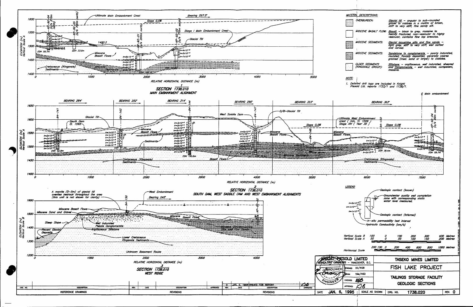
14.50
f m
Ghci'/ till - anqubar to sub-munded g m d to cobbles in a rnathx Of h C m . stiff to wry *tie firm sondy d.
~ I O C ~ W E t w u r FZOM eamft - fmctud, bloc& to non-wscufar qmfi mmsiw to to h&h&
wsicufac contains now top bmtas .
= i 1. 0ektiIm.l dnif loqs om included /i, Kni ht
Piesold L M laports l755/1 and f7&/f.
I W I O N S I RMSIONS RDWMCE O W N O S

- Knight Piksold Ltd. CONSULTING ENGINEERS
Association of Consulting Engineers of Canada
APPENDIX A
TEST HOLE LOGS
Association des Ingbnieurs- Conseils du Canada

DRILL HOLE Nc 94-141
SHEET 1 of 2 DRILLHOLE LOG KNIGHT PIESOLD LTD.
CONSULTING EN GIN E E R S
PROJECT fish Luke PROJECT No. 7 738 TOTAL LENGTH 62m79 m DATE DRILLED Jffb 26-28/94 ELEVATION U p W O x - 1552 m AZIMUTH - LOGGED BY DGSA LOCATION N 2400 E 76120 ANGLE FROM HORIZ. -90'
~
NOTES Water loss, t ype and size of hole, dri l l ing 'method, g roundwater level, etc.
'fefi-partable Val O'or fiamond dn74
ret M y cosing to 2.4 m.
?ore HO from 2.4 m with ral&mer.
Waf casing set to 67 m.
:are HO with mter only fmn E 7 m.
h p in hjdmufic feed pus- lure at 3.3-33.8 m.
fale Artesian.
'acker Test at ?9-1Z1 m an&.
VSING HulD 'Z8-26.2 m T O - 3 5 . 4 m r6. 1-11.5 m r5.3-5X6 m U4-62.8 m
rtesan /low ccoscd after outer thflated at Z9 m onb
ampfes: u- r41/1 = 8 2.70496 m
4-141/! = 2.17-12.45 m
4- 14 1/3 f
9.66-20.00 m
4-141/4 = 1.50-21.80 m
4-141/5 = 8.50-28.70 m
I - 14 1/6 = Y.80-39.00 m
4-141/7 = 9.80-49.9.00 m
1-141/8 = 1.00-51.20 m
94-141/9 = 59.52-59.74 m
n PERMEABILIN 8
d
z DESCRIPTION AND CLASSIFICATION p o I - I OF MATERIAL < a
js 7 ~ ' d ~3
cm/s 2 s
1545 i I BlwP Dark grey, fine gmined loyers of alternating weak-mad- stmng& vesicular and wggy sections. mare ccmpetent and stmng. genemlly fivctud. reddish brown at 15.1 m and 20.1 m. ing to vescic/es. 15.2-15.7 m. 20.8 m (200-300 mm wide), 22.3 m (50 mm) and at 23.5 and 236 m.
Also massive section Oisca/amo
Some chlonle stain Crwen ch/on'lizcd/clc/4y/mudstone seoms al
.
1535 i 1520 E
I v v -"I

KNIGHT PIESOLD LID. I
PROJECT tish Luke PROJECT No. ? 738 TOTAL LENGTH 62.79 m DATE DRILLED Ju/Y 26-28/94 ELEVATION UWfOx. 1552 m AZIMUTH -
E 16120 ANGLE FROM HORIZ. -90' *csA LOCATION N 2400 LOGGED BY
NOTES Water loss, type and size of hole. drilling method, groundwater level, etc.
fe /i-portable Val 0 'or lramond dnX
n
E W
I I-
Ei a i4
DESCRIPTION AND CIASSlFlCATlON u I OF MATERIAL
a a U c3
' O v V , o v
&SUE As obom 56.2-56.7 m.
Dork green wo*y c/oy/mudstone seam
E0.H. 62.79 (206 /I)

DRILL HOLE Nl 94- 143
SHEET r of z DRILLHOLE LOG KNIGHT PIESOLD LTD.
C 0 NS U LTI NG EN GIN EE R S
PROJECT fish Lake PROJECT No. r 738 TOTAL LENGTH 61-26 m DATE DRILLED Ju/v 29-37/94 ELEVATION appfox. 1562 m AZIMUTH - LOGGED BY DcsA LOCATION N 2650 E 15050 ANGLE FROM HORIZ. -90'
NOTES Water loss, type and size of hole, drilling method, groundwater level, etc.
h'el;-portoble Vol O b dkmond dnX
Set HW casthg to 1 0 m.
Core with HO from 10-4.9 w?h po&mec
:ore M? with water on& fro, C.9 m.
Peturn wter chonged from
lZ7 m. no brown moteno/ - dork b m ~ Ot 15.5-
. o s of dnX feed pressure 7 t 23.2 m.
?ore tube stuck in rods 58.1 i9.7 m, rods pulled to m v :om, some lass.
;omp/es of glaciof tfl for in0 esting not token as no fines mowred from dn7fing.
rock gene&& some os PI-141. no rock samples nken.
PERMEABILITY
cm/s
- E
0 s
6d
W
z I-
W
- - 156C
-1555
*1550
1545
1540
1535
1530
DESCRIPTION AND CLASSIFICATION u I OF MATERIAL Q < E c3 ,
0 - O ~ f f ~ N ? 0 0 O O o: Cmvel ond cobbles. heterofithic, tmce grey clox no fines
0 0-0 v v v
0
recowreg ~ C U L nu.
6u44Lc Atemating l o ~ r s of weak& to mod ond h&h& wsirufar 01
0 o wggy m?h mossive zones generol& more competent, do& o grey. fine groin&. mod. strong - strong. Some fmctured o O mnes. Lkcosionof dscofomtim from dork grey - reddish
grey below. Occasional dork grcm mmy cl~/mudstone lo wsicles.
0 0"
v v v v v v v. v
0 0 0
v o 0
.v.v ov 0 0
ova v
b v . o
I vo v
'v :v*v
; y v o v
v V v
V o
V v v
v - v - - 0 - 0 - 0 -
top ot 22.4-23.2 m m?h
' v : v 4 0 : 0
, O V v v o v o - .
0 0
V ' V m o o a vo 0'
a v V green-dork green ww cloy/mudstone ot 252-216 m. f
, V " 0
6uuLc As oboe, mod-stmng& wsculor zone Aundated with
v 0 J6.9-38.9 m. 50.6-50.8 m wi?h m y cloy/mudstone wins v random& between 26.2 m ond 36. I m from 30- 100 mm. e 45.3 m and 56.3-56.7 m.
Waxy c/oy/mudstone through motnx ond in swms
competent ond less weathered m?h some chlon?ued secthns 30-80 mm wi fe ond hoifline veins. AfosUia zones more
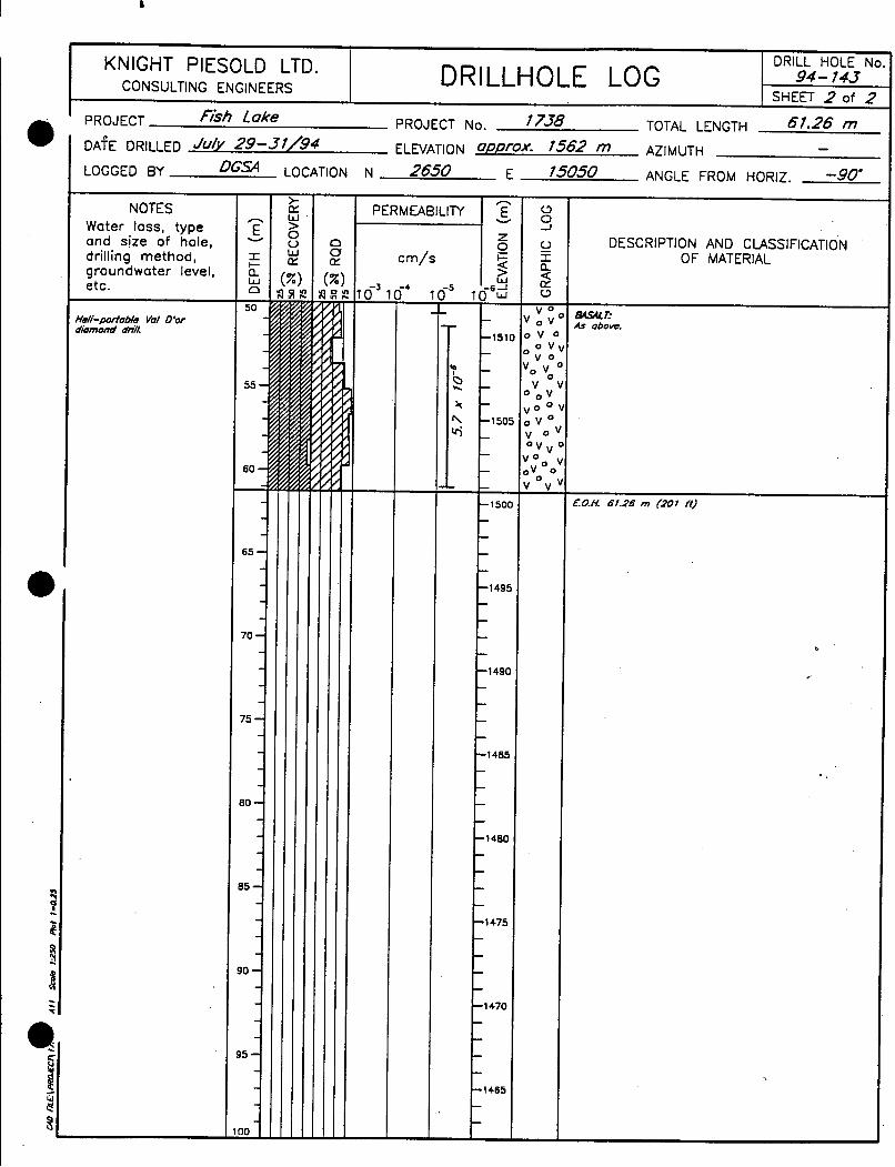
DRILL HOLE Nc 94- 143
SHEET 2 of 2 DRILLHOLE LOG KNIGHT PIESOLD LTD.
CONSULTING ENGINEERS
PROJECT No. 1 738 TOTAL LENGTH 61.26 m PROJECT F&h Lake
DAfE DRILLED Ju/v 29-31/94 ELEVATION appfox- 1562 m AZIMUTH - LOGGED BY OGSA LOCATION N 2650 E 15050 ANGLE FROM HORIZ. -90'
NOTES Water loss, type and size of hole, drilling method, groundwater level, etc.
Hdi-paftable Val O b drbmMd dnZ
PERMEABILITY
cm/s
- n E
o_ s
6 L i
v
z I-
W
- 1511
150f
- 1 SO(
I495
I490
485
400
475
DESCRIPTION AND ClASSlFlCATlON OF MATERIAL
& W E 4s above.
t0.H. 6f.26 m (201 ft)
c
a .

DRILL HOLE No. 94- 144
SHEET 1 of 3 DRILLHOLE LOG KNIGHT PIESOLD LTD.
CONSULTING EN GIN E E R S
NOTES Water loss, type and size of hole, drilling met hod, groundwater I evel. etc.
Hefi-podohle Yo1 O'or dtomond dnX
Set HW roshg to 1.8 m with p o w e c
Core HO cosing to l.8 m with powec
Core HO fmm 1.8 m with wter on&.
100% loss of return mter ot 12.5 m onmrds.
Loss of dn7l heod pressure 01 11.7-18.9 m ond 7 Z ? m.
folfing Head Test corned out in cumpfeteti monitonng well between compktibn zones ot M.8-70.1 m.
PROJECT No. 1 738 TOTAL LENGTH 140.51 m DATE DRILLED AuQust 2-6/94 ELNATION *.WfoX* I610 m AZIMUTH - LOGGED BY LOCATION N 3100 E 14050 ANGLE FROM HORIZ. -90'
- >. W > 0 u W LT
a 0 rY
I h 4 -
DESCRIPTION AND CLASSIFICATION OF MATERIAL
OMXWUUO&X- Glociol I24 sondy cloy. grovel ond cohhles.
&IIuLc Aftemoting loyem of dork grey - dork greenish grey weo&& vasiculor - mod. ond high& wsiculor ond wg9y with some geneml& mom competent mossiva zones. fine p ined. mod. - s!mng, SW-F with zones o i mod. - high& wsiculor (nundoted wtth green - do& green may cloy/ mudstone. in vesicles ond penem/& thrvugh motnk Occosionof light ton cioy/mudstone on joints ond in motnx. soft. Also some g m i s h &own mudstone swms to 250 mm wife, but genemlQ 20-50 mm.

DRILL HOLE No 94- 144
SHEET 2 of 3 KNIGHT PIESOLO LTD. DRILLHOLE LOG CONSULTING ENGINEERS
PROJECT fish Lake PROJECT No. 1 738 TOTAL LENGTH 140*51 - DATE DRILLED AWusf 2-6/94 ELEVATION oW~ox* 1610 m AZIMUTH
LOGGED BY D c a LOCATION N 3100 E 140.50 ANGLE FROM HORIZ. -90'
NOTES Water loss, t ype and size of hole, d iil I in g m e t hod, groundwater level, etc.
Hefi-padable Val D'or damond dnZ
Pol/umer used at 84.1 m to stablke hale after packer tes
Cora HO with wotw on& fmn 87.1 m.
Onil mds pulled to m n r r core lube from 91.7 m.
PoI&mw used at 115.3 m after Packer Test. Care HO m?h uvter on& fmm 12&0 n
Hole ffushed far 10-15 min. befm Packer rest.
- n E
W
E W
PERM EABl LlTY
c m / s DESCRIPTION AND CLASSIFICATION z o _ u
.6 -IJ 5 10 w upprox. 1610 m
+ I OF MATERIAL W s 5 $ 1560 V 0 v 1
0 e Ar oboe.
t i - t x w z m I G . ' 4- ' +' ' +- {Round - submund fine, coarse gmw4 cobbles, loose, stma bo.&?: maink washed oway by drtlfing.
A/ternaling laprs of dad gray - dad greenish gray massti 25 5: - mak& and mod. - high& wskulor ond wggy as above. - V p - fine grain&. mod stmn - strong. inundated A zones by V= v,- do& gmen
Mass& zones
zqv more competent and less weathered wilh same chlan?iired sections. 1540 avo;
- -'545 - v;v,-, & W E
V -
Woay clay!udstons thmugh matnk and h -" seams 33-80 mm wife ond haidhe wins
V 0 0 oVo. .V0" e o
V
- 0 v O 0
-1535 O v ' O - 0
- 0 v-o- v - ov - o-vo v 0 vo- - 0 - - _ v o

DRILL HOLE Nc 94- 144
SHEET 3 of 3
PROJECT Fkh Luke PROJECT No. 1 738 TOTAL LENGTH 140.51 m
DRILLHOLE LOG KNIGHT PIESOLD LTD. CON S U LTI NG ENGINEERS
DATE DRILLED A w m t 2-6/94 ELEVATION oppfox- 1610 m AZIMUTH - E 14050 ANGLE FROM HORIZ. -90' LOGGED BY D G a LOCATION N 3100
NOTES Water loss, type and size of hole, drilling method, groundwater level, etc.
- E
a a
v
E w
100 -
105 -
110-
115-
120-
- -
125- - - - -
30 - - - - -
35 -
- >- E W > 0 0 W E
a 0 E cm/s
DESCRIPTION AND CLASSIFICATION OF MATERIAL
GRMucmnuosm~ Greenish brown. fine gminsd, well indumted but friable. poor& graded gmve4 t e e o f cobbles.
w4uLILITc: Greenish bmwn - greenish grefi weakly - mod. Adumtsd growl and cobbles, some sand paw& gmdd, same sandy motni nrowrcd but generally little or no fines recave&. fmclurrrd - loose clasts. same green chlon?ic clay/mud- stone.
AlrX;dlUE: Dark greenish grey-block. lamhated - bedded. occwsmnol light grey. high calci?e content. fmcturcd w?h same more competent less fmctursd zones, weak - mod. strong. Jointing gencml& smooth - slickenskdes.
_I

9 0 f 3
DRILL HOLE Nc 94- 147
SHEET 1 of 2 DRILLHOLE LOG KNIGHT PIESOLD LTD.
CONS U LTI NG EN G I N EE R S
94.79 m TOTAL LENGTH PROJECT fish Lake PROJECT No. I 738
LOGGED BY DcsA LOCATION N 3650 E 130.50 ANGLE FROM HORIZ. -90'
NOTES Water loss, type and size of hole, drill ing method, groundwater I eve I, etc.
tfefi-ptutab/e Val O b diomond dnZ
Set wt?h cashg to 6.4 m.
Cam HO fm 2.7-7.9 m wit1
Care HO with mater an& from Z 9 m.
$my sand wvshed out of ivsrburden in top 6.4 m and accumulated around casng 01 wrtme.
PO&mCC
DAcm rrm 9.7-11.1 rn 56.6-7UO m 7a8-8~2 m M9-94.8 m
?ULLfNC Hc4D ES75 15.7-23.9 m
24.8-3.3 m 3.11-41.5 m 42.2-50.6 m 49.?-%2 m 60.5-b8.9 m
PERMEABILITY I 2 c m/s
.a -
L I I
I
u s DESCRIPTION AND CLASSIFICATION
OF MATERIAL 0 r a a
<?TO'
E (3
o,-,.-
;zro= .o .o!!.
Y o
y;
o--At Brawn sandy clay, same g m 4 tmce cabb/es, dense with grwn clay and basalt clasts ot lower cantact. cL*cuL ML vo-. 0-V
.-a T 0' - . O -
v'ov ov 0 v V D V O . v a n
B W E Alternating lqyers of dark grey, weak& Vrsicuhr to mad. an strong& and wggy vesicu/ar, fine grained with massii sectians marc campetent. lanes of mod. - strong& isicular inundated with grwn - dark grwn, weak waxy c/ay/mudstane through matrix, well Adurnled. and in seams 10-90 mm wide between 35.4 and 17.5 m.
o v 1! v o - /
- 0 v - 0
-v - - v < 1 /SWVWE-RNE Well indumted but WDS?VN& /nablee greenish brawn. Bedding oppmx. A+-+* 9cT to care axis. On# breaks along bedding planes.

DRILL HOLE No
SHEET 2 of 2 94- 147 DRILLHOLE L O G , KNIGHT PIESOLD LTD.
CONS U LTI NG EN GI N EERS
PROJECT fish Luke PROJECT No. r 738 TOTAL LENGTH 94.79 m
NOTES Water loss, type and size of hole, drilling method, groundwater level, etc.
Vel;-portable Val D'or ftomond dnll.
5 -
I )* i
1510
150: i
DESCRIPTION AND CLASSIFICATION 0 I OF MATERIAL a 4 E c3
0 n o
C u c K I U c ~ m . .Sz?Srn€ - U T : Soft, wa// indumted. WM, fight gmy-betge saw UKTWd to dark grey - greenish gny - grrrnish brown CIA-. Dn?/ induced b r e o h on&. con oxis.
Bedding pfones appw. 9U to Becoming drnser ond more cfofly w?b depth.
1490
1485 I V_e-v_". - - - Dark grefi med. gmined mossiw - v. weak !es&ulac mod.
O V . 0 v0.v: .o 0 0 0
strong intarbedded will, loase gmwl ond occoston01 green wory clay/mudstone. ; "0;
0 0 , -aum%IE: 0 ," 0 k r k grwnkh gny. poor& sorted, weak& - wll indumted.
munded. submunded ond subongulor cfosts. hetervfithic set O?:Of ifl weak dank green cfay/mu&tone ond sondstone hter- oo 0 bedded with mossivw lX.%T flows. Competent congfomer-
ole mod. strong - strong. v . . v v

-
e
DRILL HOLE No 94- 148
SHEET 1 of 1 KNIGHT PIESOLO LTD. DRILLHOLE LOG CONSULTING EN GIN E E R S
-.
TOTAL LENGTH 29.26 m ' PROJECT Fish Lake PROJECT No. I 738 DATE DRILLED August 11- 12/94 ELEVATION ap~rox. 1502 m AZIMUTH -
E 12150 ANGLE FROM HORIZ. -90' LOGGED BY D G a LOCATION N 4200
NOTES Water loss, type and size of hole, drilling method, groundwater level, etc.
Vefi-portobfe Vof D'or fbnond dn2
Yet wt?h M y coshg to 3.0 I;
rill, po&mer.
:ore HQ fmm 0.6 m with !ofper.
illlfNC HDO rrsrS !4-14.0 m IO -232 m
lde flushed for 10-t5 mh. Isfore each foffhg Hwd res
'ors HQ wt?h p-ef fmm 6.2-29.3 m.
i7t - fine sand washed up w h g to s u h e fmm zone !4- 11.5 m continuous&.
Hde making h&h wlume of sone squeeahg and ww tigi on mdr
Hole lost at 29.3 m due to Pond stkkhg to e. Somples:
94-148/1 = 4.8-5.5 m 94-118/2 = 6.4-X2 m 94-148/3 = 61.5-&8 m
94-148'4 a 9.8-10.5 m 94-?48/5 = 10.5-10.9 m
- > fY W > 0 u W fY
PERMEABILITY I L
cm/s I 1 s 4 DESCR l PTl ON AND CLASS I Fl CATION
OF MATERIAL
%cML nu: 9rawn sa& cloy. trace sand g r a d and cobbfes. subongufor - submunded. stiff - v. stiff ond wefl indurated ta 6.4 m. nterbedded with soft sil& cfofi trace sand gravel ond :obbles. partiol& intoct ot 2.4-3.7 m. Brawn clapy sond iilty sand - sondy sdt with grovef ond cobbles, v. stiff - io&. competent ond weN indurated 6.4-9.8 m with drin Ireaks per.. to core axis.
?LZS?WC Imwnikh grey silt - fhe sand med dense, soff v. soft morning coorser to s a n e s~tsione ond wok& indurated. hndy sections more friobfe.
72rnOAfGW?E.: round - subround - subangulor gmvel ond cobbles. heter Ifithic. wwkly - we# indurated with bmwn - greysh bmn - brownish green sane cloy - clayey sand ma&>. vdurated zones more competent. Some weathered vesicuh wsolt fmgments ond omsionof basalt badder present, nn . high& m t h e n d ond fhonite stoined towurds bose. :enemf& compnsed of loose gmwfs ond cobbfes m?h loss he sonds from motnx between 14.0-16.2 m ond 1610- '4.4 m.
No beddng en'dent.
Well
?&y, fine grained weok& wsiculor to mossiw, mad 'Trig, conglomerate zone 30 mm ot 24.8 m ond mudsfon vn IO-7V mm at 25.3 m. wtXQu€rnE: mkfy - welf hdumted greenish bmwn sane matffk with uvel ond cobbles, braken zones with some foose. gmvel id cobbles. hetemfithic. some firnonits staining. bosalt cfom
0.H 29.26 m (96 ft)

I
DRILL HOLE No. 94- 750
SHEET 7 of 7 DRILLHOLE LOG KNIGHT PIESOLD LTD.
CONS U LTI N G ENGl N E ERS
PROJECT fish Luke PROJECT No. 7 738 TOTAL LENGTH 38.4 m
LOGGED BY D G s LOCATION N 4.950 E 77250 DATE DRILLED Affgffsf 73- 75/94 ELEVATION appfox* 7525 m AZIMUTH
ANGLE FROM HORIZ. -90'
NOTES Water loss, type and size of hole, drilling method, groundwater level, etc.
Heli-portable yo/ D'or dhmond dn71
Set HW cashg to I7 m will; po&mer.
Core HO f m 1.8 m with pal&me
Core HO wi# wter on& fmn 9.4 m.
Hale flushed far 10 mh. pno la f k t Packer Ted.
SOX /ass of return wter at 13.4 m.
Packer set at 17.8 m far tea nos. J and 4.
Hole squeezing ot f8.3- I62 m.
Samp/es: 94-150/1 = 29.3-29.5 m Os-lSO/2 = 331-35.2 m 94-150/3 = 34.0-34.2 m
Rods remaved awrnght to change worn out s t . After re-instalfed the care tube got stuck A the care bar& by g m sand at ap-. 30 m.
No green sond mcowmd or f/ushsd to surfocs dunng drilhng. Sand more than h h l wshed out of loase gmval and congfomemte zanes. bncfghg hale.
Hale lost at a 4 m com- plete& mndcd in fmm 29.2- 38.4 m.
> W > 0 u W CY
a
cm/s
i4
I-
' 15001 % hh 1495
149
DESCRIPTION AND CLASSIFICATION OF MATERIAL
M E 8 U H . %vel and cobbles set in a redd& brown stiff sand day 4 Imwnish grey sondy clay. tmce s2t. stiff -. v. stift com- 7etent. CUClrll l?U.
W C lark grey - greenish gray. fine gmined weak& - strong& esicdar and vuggy but most& mossiw and competent, nod stmng. mc(ured below. d with some grwn*h blod mudstane inundating maink. iome soft turquoise g m n infill to vesicles, c/ay at 34- 1.9 m. msionI& in matnx.
f?nctured zones h 2.7-7.9 m becaming les3 Contact *r?h ti71 b mod - high& weathe,
Tmce dork green doy/mudsfone an fmctures and
ubangulac munded - submunded g m h tmce rabble fasts heat+ Kinonite stained genemi& hose and bmken ill, a greenish sandy mafnk, mast& m h e d amy. Intact anglomemte occasianaf& present in weak& - mod Aduml 9 sections. which is more competent.
pea@ sad&. Very Kttfe mcawry a/ fines.
0." 0 . -0 .
0 .d Uoth gcnem/&
.o p
O 0'
O . 0
,Po. 0
P .: ?o ' 0
- 0 e .
I . .
0 . 6 - -- - - - - - - & , ~ r e d pumf/ef to bedding. - - -- - oms. Kinvswle Sediments.
io Opdlo- Paor& d&?round to well-rounded hefemfithk clasts, o-oa'o green - g m i s h gre& black aqifitic and dark - Kght O:"-O=? grey h a greenkh grey med gmined mndy matr& /ocal& .*g$fo crumb& and sheared with colde veins and tmce quartz in . 0-0 thin strings. 0~0: L' Kingstv1.z sediments.
Bedding appmx. pamild to ca -- ?.-W17 C0Ivr;Lmm :

- Knight Pibsold Ltd. CONSULTING ENGINEERS
APPENDIX B
EXPLORATORY DRILLING BEDROCK LOGS
Association Association of Consulting des Ing4nieurs- Engineers Conseils of Canada du Canada

PROJECT N O . - ~ - -
S H E E T 1 O f -4, EXPLORATORY DRILLING - BEDROCK L O G KNIGHT AND PIESOLD LTD. CONSULTING ENGINEERS
PROJECT f=la h DRILL H O L E No. 94-141 REF. EL. ANGLE F R O M HORIZ.
D A T E T U L Y 27/94 CONTRACTOR @6f 6 f l h o c \ BEDROCK EL. BEARING LOGGED B Y sd CORE SIZE k? T O T A L L E N G T H COORDINATES N
E a
I IRILLING INFO.( LITHOLOGY ROCK MASS DEFECTS 0U-l
I-13 2s ROCK DESCRIPTION 4 o z g uz- L d o E "t=' 9 13 Weathering, structure, color, grain s ize , I L d U I w tx sa [2: 2: 1 strength, rocktype. Other comments.
I
2-3
lo -
DEFECT 0 E S CRlP Tl@N
Type , shape, roughness. infilling
. . . . - . . ._ . ..~ . .. . .

0
EXPLORATORY DRILLING - BEDROCK LOG KNIGHT AND PIESOLD LTD, COIJS \JL T ING E NGlNE ER S
.- PROJECT N o . f l & - - -
SHEET 2 -0F-4-
-------_--
P R O J E C T g 6 d h k 4 DRILL HOLE NO. 91i-lU.I REF. E L . ANGLE F R O M HORIZ .
D A T E 27/9 4 C O N T R A C T O R Q U a T C h A g n BEDROCK EL. BEARING -- C O R E SIZE T O T A L L E N G T H 2dCk. C 0 OROlNA T E S N LOGGEO B Y -
IRILLING INFO
E
LITHOLOGY I ROCK MASS DEFECTS I I I
ROCK DESCRIPTION
Weathering, slruclure. color, grain sizo. strength. rocktype. Other comments.
I- C> I11 11. L I J n
2- 3 - -
OEFECT DESCRlPTlt3N
Type, shape, roughness, infilling

PROJECT ria. i738 I EXPLORATORY DRILLING - BEDROCK L O G I OF 4 KNIGHT AN0 PIESOLO LTO. SHEET--
C 0 tl SUL T ING ENGINE E RS
ANGLE F R O M HORIZ. -90" B EARING
PROJECT 6 S K DRILL HOLE NO. 94 -14 I REF. E L . - D A T E A c ONTR A c TOR -4 BEDROCK EL. LOGGED BY *SA CORE SIZE kk) T O T A L L E N G T H COORDINATES N
DRILLING INFO LITHOLOGY I ROCK M A S S DEFECTS
ROCK DES CRlPTlON
Weathering. structure, color, grain slzo, strength. rocktype. Other comments.
A I I
DEFECT DESCRlPTleN
t i l LA. 2 W O
T y p 0 , shape, r olio hn o s s, in I illing

PROJECT No. 1738 EXPLORATORY DRILLING - BEDROCK LOG
S H E E T L O F ---.I 4- KNIGHT AND PIESOLD LTD.
COIJSULTING ENGINEERS
PROJECT FlS4 7 y DRILL HOLE No. 94-)4\ REF. EL. ANGLE FROM HORIZ.-9O0
DATE 28 4 CONTRACTOR Q U G T BEDROCK EL. BEAR IN6 -__ ______- LOGGED B Y CORE SIZE TOTAL LENGTH 206w COORDINATES N
IRILLING INFO.^ LITHOLOGY
> \ I n ROCK DESCRIPTION 2 0 u)
Weathering, struclure, color, graln size, strength, rocktype. Other comments.
I W ll.
-~
ROCK MASS DEFECTS I I
DEFECT DESCRIPTIBN
Type, shape, roughnoss, infilling
I

PROJECT NO. 17%- SHEET&-OF - - i - EXPLORATORY DRILLING - BEDROCK LOG KNIGHT AND PIESOLD LTD.
C ON SUL T ING EN GlNE E R S
DRILL HOLE No. 94-14-3 REF. EL. __ ANGLE F R O M HORIZ. CONTRACTOR &=T *m BEDROCK EL. BEARING
LOGGED B Y w% CORE SIZE T O T A L L E N G T H C 0 OR DIN A T E S N E
I
IRILLING INFO LITHOLOGY I ROCK M A S S DEFECTS
u) u) w 2 tK n a r
% g I-0- -1s I-G
1 si 0
ROCK DES CRlP TlON uz ~ A J U E gk! z z IrJa.- ::Iz Weathering, strucluro, color, groin size, l ~ a u 1 1 1 1
strength, rocktype. Other comments. o m ng
DEFE C T DES CRlP TleN
Type, shape, roughnoss. infilling
2 -3
I
>lo
1 t Io
5-L - !- 3
LJ

EXPLORATORY DRILLING - BEDROCK L O G KEJIGHT AND PIESOLD LTD. C O I I S U L T I N G ENGINEERS
IRILLING INFO
- _ 17% P R O J E C T No. --
S H E E T A - OF-%-
------
L
I
LITHOLOGY
LL
I- L 0 5 L l J c L L .-
ROCK DESCRIPTION
Weathering. structure, color, grain slzo, strength. rocktype. Other comments. 2:
L
. -
ROCK MASS DEFECTS
DEFE C T DE S CRiP TIBN
Typo, shape, roughnoss, infilling

PR 0 JE C T N o . I738 ---- EXPLORATORY DRILLING - BEDROCK L O G SHEET-- 3 OF- 5 KNIGHT AND PIESOLD LTD.
C 0 NSUL TlNG ENGINE E R S
ANGLE F R O M HORIZ. -90" PROJECT 77 h k e DRILL HOLE No. 94-143 REF. EL.
D A T E %L 94 CONTRACTOR Q&Sf &f@ A BEDROCK EL. BEARING
LOGGED B Y D m CORE SIZE TOTAL L E N G T H COORDINATES N c
IRILLING INFO.^

0
PROJECT tJa. 17% SHEETLOF 5 EXPLORATORY DRILLING - BEDROCK L O G KNIGHT AND PIESOLD LTD.
CONSULTING ENGINEERS
1
g .-... '.
PROJECT &k..17u DRILL H O L E No. 94-143 REF. EL . ANGLE FROM HORIZ. -90 D A T E ToL 309 CONTRACTOR d h 5 T BEDROCK EL. BEAR INC LOGGED B Y D&A CORE SIZE HQ T O T A L LENGTH COORDINATES -N
E
IRILLING INFO.( LITHOLOGY I ROCK MASS DEFECTS I ROCK DESCRIPTION
Weathering, struclure, color, graln slzo, strength, rocktype. Other comments.
DEF EC T 0 E S CR IP TlON
Typo, shape, roughnoss. infilling

.
PROJECT No. 1 7 5 8 5 SHEETL OF
EXPLORATORY DRILLING - BEDROCK L O G KNIGHT AND PIESOLO LTD.
PROJECT F\su h LE DRILL H O L E No. 94 -143 REF. E L . ANGLE F R O M HORIZ. -7b D A T E s U i \ l 3'!9(1 CONTRACTOR (30- 'T &M& BEDROCK EL.
LOCGEO B Y b M A CORE SIZE T O T A L LENGTH C OOR DIN A T E S
CONSULTING ENGINEERS
El EAR ING
N
IRILLING 1 ~ ~ 0 . 1 , LITHOLOGY I ga I - t 3 - 0 -It; l-c
w 3 E 2: p 0 Weathering, structure. color, graln s h e . [La " I L I I
g y . a p o w r , \ , , I % (L 0
z UI R 0 CK DES CRlPTlON u) W 2 v z
(L a strength, rocktype. Other comments.
--
--
'I'

PROJECT No. 1738 SHEET-OF 10
KNIGHT AN0 PIESOLO LTD.
PROJECT Flstt DRILL HOLE No. 94.-1@-- REF. EL. ANGLE FROM HORIZ. -90"
EXPLORATORY DRILLING - BEDROCK L O G CONSULTING ENGINEERS
BE A R ING -
C 0 0 RD IN A T E S
DATE 2/94 CONTRACTOR @ UEST BEDROCK EL. LOGGED BY OGSO CORE SIZE TOTAL LENGTH *SI m N
IRILLING INFO

EXPLORATORY DRILLING - BEDROCK LOG KNIGHT AND PIESOLD LTD. CONSULTING ENGINEERS
~
PROJECT FISH &%Z DRILL HOLE No. 9(c-l@ REF. EL. ANGLE FROM HORIZ. -40" D A T E A G 2/ 94 CONTRACTOR U€sT BEDROCK EL. BEAR IN G
CORE SIZE TOTAL LENGTH r40-51 n) COORDINATES N LOGGED BY DGSQ E
I I
PROJECT N o . 1 7 3 8
SHEET 2 O F k
IRILLING INFO.( LITHOLOGY I ROCK MASS DEFECTS
ROCK DESCRIPTION
Weathering, structure. color, grain size. strength, rocktype. Other comments.
L O DEFECT DESCRIPTION
$? I W O Type, shape, roughness, infilling

PROJECT No.
SHEET 3 OF 10 KNIGHT AND PIESOLD LTD.
PROJECT !=6H LAKG DRILL HOLE No. 94-144. REF. EL. ANGLE FROM HORIZ. -90' OATE AGd 94 CONTRACTOR QUE ST BEDROCK EL. BE ARlNG LOGGED BY sa CORE SIZE TOTAL LENGTH 1@-51M
EXPLORATORY DRILLING - BEDROCK LOG CONSULTING ENGINEERS
N COORDINATES
IRILLING INFO
E
R 0 CK DESCRIPTION
Weathering, structure, color, graln size, strength, rocktype. Other comments.
DEF E C T DES CRlP TlON
Type, shape, roughness, infilling

PROJECT N o . 1 7 3 8
EXPLORATORY DRILLING - BEDROCK LOG SHEET& OFL KNIGHT AND PIESOLD LTD.
PROJECT FISH &-e DRILL HOLE No. 94-/44L REF. EL. ANGLE FROM HORIZ. -90"
DATE A-m 3/94 CONTRACTOR 7 BEDROCK EL. BEAR IN G
CONSULTING ENGINEERS
LOGGED BY?-, CORE SIZE tf0 TOTAL LENGTH IW-51 COORDINATES N
DRILLING INFO
E
LITHOLOGY I ROCK MASS DEFECTS
ROCK DESCRIPTION
Weathering, structure, color, grain size, strength, rocktype. Other comments.
LL
I &k&L/a5 - 1z3
DEFECT DESCRIPTION
Type, shape, roughness, Infilling

s L
F C
210
2 16
22 I
Zad
23\
2%
24 I
z4&
2.51
253
EXPLORATORY DRILLING - BEDROCK LOG KNIGHT AND PIESOLD LTD. CONSULTING ENGINEERS
PROJECT No.-
SHEET-OF JO
PROJECT clsk! LAUC’ DRILL HOLE No. 94-144 REF. EL. ANGLE FROM HORIZ. -90” D A T E A& g94 CONTRACTOR BEDROCK EL. BEAR IN G
LOGGED BY -SA CORE SIZE T O T A L LENGTH 140.51M COORDINATES N E
I
IRILLING INFO.^ LITHOLOGY I ROCK MASS DEFECTS
0°C” 0‘ >.
LZ z: u) ROCK DESCRIPTION w 0 2 2 W G E 2k IAJW n Weathering, structure. color, graln size, I w k!g IA-2 I 0%- - 2in lYLL ns % strength, rocktype. Other comments. a
be, -10 u1
ha” a
DEFECT D E S CR IP TlON
Type, shape, roughness, infilling

PROJECT No. 173% SHEET 6 OF 10
EXPLORATORY DRILLING - BEDROCK LOG KNIGHT AND PIESOLD LTD. CONSULTING ENGINEERS
PROJECT f%H DRILL HOLE No. 94-,44 REF. EL. ANGLE FROM HORIZ. -90' DATE 3/44 CONTRACTOR @mT BEDROCK EL. BEARING LOGGED BY D M CORE SIZE HQ TOTAL LENGTH C 0 OR DIN A T ES N
IRILLING INFO

EXPLORATORY DRILLING - BEDROCK LOG KNIGHT AND PIESOLD LTD. CONSUL TlNG ENGINEERS
\ v ) ROCK DESCRIPTION
Weathering, structure. color, grain size. 1 w strength. rocktype. Other comments.
LL
PROJECT No. i738 SHEET 7 OF lo
L V > I DEF E C T DES CRlPTlON
Type, shape, roughness, infilling

PROJECT No. (738 SHEETLOF 10 EXPLORATORY DRILLING - BEDROCK LOG KNIGHT AND PIESOLD LTD.
PROJECT 6 s H DRILL HOLE No. 94 - I 4 4 REF. EL.
DATE 4& 5/94 CONTRACTOR Quescr BEDROCK EL. BE ARlNC
CONSULTING ENGINEERS
ANGLE FROM HORIZ. -90°
COORDINATES N LOCCEO BY CORE SIZE HQ TOTAL LENGTH lQo-5 Im
IRILLING INFO.^ LITHOLOGY
>- \ (A ROCK DESCRIPTION e zl9 u) w w g' 0 Weathering, structure, color, graln size,
cj 03; g 22 $ p 0s ix strength, rocktype. Other comments. w
LL LL
ROCK MASS DEFECTS
DEFECT 0 E S CR IP TlON
Type, shape, roughness, infilling
- I
- I

PROJECT NO. 1738 SHEET 9 OF l o EXPLORATORY DRILLING - BEDROCK LOG KNIGHT AND PIESOLD LTD.
CONSULTING ENGINEERS
PROJECT FIsq DRILL HOLE No. 94444 REF. EL. ANGLE FROM HORIZ. -90° D A T E CONTRACTOR Qu-7 BEDROCK EL. BEARING
LOGGED BY OGSfl CORE SIZE stc;! TOTAL LENGTH Ib51 m COORDINATES N E
I
DRILLING INFO, LITHOLOGY I ROCK MASS DEFECTS
(A 4 I, ROCK DESCRIPTION
Weathering, s truclure, color, grain slze, strength, rocktype. Other comments.
DEFECT DES CRlP TlON
Type. shape, roughness, infilling w 2 0
I a a
Ill c
e
-
le"
lOa -
1-5
7- 8

DRILL HOLE No. 94-144 REF. EL. ANGLE FROM HORIZ. -90" CONTRACTOR Qo a7 BEDROCK EL. BEARING CORE SIZE H Q TOTAL LENGTH l b 5 l w C 0 0 R D IN A T E S N
DATE LOCCEO BY
EXPLORATORY DRILLING - BEDROCK LOG KNIGHT AND PIESOLD LTD.
CONSULTING ENGINEERS PROJECT N o . 1 7 3 8
SHEET 10 O F k
~
IRILLING INFO
12- 25"
I2 - 25' -
LITHOLOGY
u) u) w 2
U
n a r
ROCK DESCRIPTION
Weathering, s truc ture, color, grain size, strength, rocktype. Other comments.
E
ROCK MASS DEFECTS I
>- DEFECT DESCRIPTION t-0 V Z
:% Type, shape, roughness. infilling 1.1 0

0 0
PROJECT NO. t73g SHEET i O F 7
D A T E 8 94 LOGGED BY DGW CORE SIZE 1- TOTAL LENGTH 94-7% COORDINATES N
EXPLORATORY DRILLING - BEDROCK LOG KNIGHT AND PIESOLD LTD.
PROJECT z H ,ha DRILL HOLE No. 94-/47 REF. EL. ANGLE FROM HORIZ. -90"
CONSULTING ENGINEERS
CONTRACTOR O € s T BEDROCK EL. BEARING ~
E
ROCK DESCRIPTION
Weathering, structure, color, graln size, strength, rocktype. Other comments.
DEFE C T 0 E S CRlP TlON
Type, shape, roughness. infilling

EXPLORATORY DRILLING - BEOROCK LOG KNIGHT AND PIESOLD LTD. CONSULTING ENGINEERS
6
PROJECT 6Skf be DRILL HOLE No. 94 -147 REF. EL. ANGLE FROM HORIZ. -90 DATE A-w- @h(l CONTRACTOR 6U-T BEDROCK EL. 8 EAR ING
LOGGED BY WsA CORE SIZE TOTAL LENGTH 94-79m C 0 0 RD IN A T E S N
DRILLING INFO.^ E
PROJECT No. i7;38 SHEET 2 OF 7
LITHOLOGY I ROCK MASS DEFECTS gul
0 u)
*a 2 w J E 9f 0 Weathering, structure, color, grain size, ~w k!g bqo ng- 2ia 02 a
t-g- 4 l-r R 0 C K DES C R IP TlON u) w
(I
I strenglh, rocktype. Other comments.
, lYk 2 (30 0
c t - p$ -40
9c
DEFECT DESCRIPTION
Type, shape, roughness, infilling
S-51 As
i l

PROJECT NO. 173f3 SHEET- 3 O F 2
EXPLORATORY DRILLING - BEDROCK LOG KNIGHT AND PIESOLD LTD. CONSULTING ENGINEERS
DRILL HOLE No. 94-147 REF. EL. ANGLE FROM HORIZ. -70" CONTRACTOR QUEST BEDROCK EL. E EAR IN G
N E
LOCCEO B Y DG;sA CORE SIZE RG T O T A L LENGTH 94-79fW COORDINATES
DRILLING INFO.^

EXPLORATORY DRILLING - BEDROCK LOG KNIGHT AND PIESOLD LTD. CONSULTING ENGINEERS
c PROJECT FiSt.1 #kG DRILL HOLE No. 94-147 REF. EL. ANGLE FROM HORIZ. -90 DATE a&- 9 / w CONTRACTOR 6)U-T BEDROCK EL. BEARING -
LOGGED BY D& CORE SIZE ffa T O T A L LENGTH 94-79 F3 COORDINATES N c
PROJECT No. I 7 3~
SHEETL OFL
DRILLING INF 0.1 LITHOLOGY I ROCK MASS DEFECTS
DEFECT DES CRlP TlON
T y p e , s h a p e , roughness , infilling

EXPLORATORY DRILLING - BEDROCK L O G KNIGHT AND PIESOLD LTD. CONSULTING ENGINEERS
PROJECT No. 17'38 SHEET 5 OF-
PROJECT 65kt DRILL HOLE No. %' 447 REF. EL. ANGLE FROM HORIZ. -?aG DATE AuQ 9/3@ CONTRACTOR 0U-T BEDROCK EL. BEARING
LOGGED BY & CORE SIZE T O T A L LENGTH 94-79M COORDINATES N c
LITHOLOGY ROCK MASS DEFECTS IRILLING INFO,
ROCK DESCRIPTION DEFECT DESCRIPTION
Type, shape. roughness. infilling Weathering, structure, color, graln size, strength, rocktype. Other comments.
a ' a- v)
AS &me bog
58z -
0%
-2

0 0
PROJECT No.-
SHEETA OF^ EXPLORATORY DRILLING - BEDROCK LOG KNIGHT AND PIESOLD LTD. CONSUL TlNG ENGINEERS
PROJECT 6% DRILL HOLE No. '34'4$7 REF. EL. ANGLE FROM HORIZ. -90' DATE h0- 9 4 io/% CONTRACTOR 0U-T BEDROCK EL. BEARING
LOCGEO BY CORE SIZE T O T A L LENGTH 94-79, COORDINATES N
IRILLING INFO

PROJECT No. KNIGHT CONSULTING AND PIESOLD ENGINEERS LTD. I EXPLORATORY DRILLING - BEDROCK L O G I&
~ _ _ _ ~~ ~~
PROJECT h M DRILL HOLE No. 94-147 REF. EL. ANGLE FROM HORIZ. -90' DATE &- (u/4)rc. CONTRACTOR QUGS7 BEDROCK EL. BEARING
LOGGED BY m9 CORE SIZE ff(? T O T A L LENGTH 96 -791V C 0 ORD IN A T E S N
LITHOLOGY I ROCK MASS DEFECTS IRILLINC INFO - u) w J a. I 4 cn -
DEFECT DESCRIPTION
Type, shape, roughness, infilling 4 9 LLI
Weathering, structure, color, graln size, strength. rocklype. Other comments.
. -, .
A
.-

0' '
EXPLORATORY DRILLING - BEDROCK L O G KNIGHT AND PIESOLD LTD. CONSULTING ENGINEERS
n & b
i$ C
3-7
8
( 2
IS-5
21
26
31
36
41
46
PROJECT No. 1738 SHEET- 1 OF 3
IRILLING INFO.
5 : a = g2 2 :
> - J w w 0
z = u u a .
~ ~~~ ~~
LITHOLOGY ROCK MASS DEFECTS
\ (A ROCK DESCRIPTION g >- DEF E C T DES CRlP T l 6 N
G Z 2 :SE 2: "a ;$ -1: a strength, rocktype. Other comments, 1~1%- L3 %n ge ns 0 1
I-a- -Is I-; t-0
08 $% 0 LL
213 VI
Type, shape, roughness, infilling k2 * 9 z g Weathering, structure, color, graln size, I L q O I w : g
LL
- l i - t - I - - I I - I - I - I
I ---- - I I I I 1 1 - 1 - 1 - I

EXPLORATORY DRILLING - BEDROCK L O G KNIGHT AND PIESOLD LTD.
C 0 N S UL T I N G EN GIN E E A S
I-1
L L
\ V I ROCK DESCRIPTION g z
- € V I z 2 0 u1
g : y b"m
y s' 0;
g:
w w w = - m i 2 a. 32 q c o W e a t h e r i n g , structure, color, grain size, a
a o v 0: SS 2 s t r e n g t h , rocktype. O t h e r comments. LL
PROJECT NO. 1738 SHEET- OF 3 2
E
IRILLING INFO. LITHOLOGY ROCK MASS DEFECTS I I I I I
DEFECT DE SCRIP TleN :VI 0 s - 4 t-; t-u *u "3
a e c 0 LL
: J I w k!g T y p e , shape, roughness, infilling E@ $2
o w -
ELI cz

EXPLORATORY DRILLING - BEDROCK LOG KNIGHT AND PIESOLD LTD.
C 0 tJSUL TlNG ENGINEERS
1 I I I I . I I
PROJECT No. I738 SHEET-, O F 3 3

Q
EXPLORATORY DRILLING - BEDROCK LOG KNIGHT AND PIESOLD LTD.
CONSULTING ENGINEERS
c PROJECT No.
SHEET OF 3

EXPLORATORY DRILLING - BEDROCK LOG KNIGHT AND PIESOLD LTD. CONSULTING ENGINEERS
PROJECT 65tf cAt(E DRILL HOLE No. 94- -1% REF. EL. ANGLE FROM HORIZ.
DATE b G Id944 CONTRACTOR 0U-T BEDROCK EL. BEARING __ LOGGED BY CORE SIZE m, T O T A L LENGTH 38-4.M COORDINATES N
E
PROJECT N o . 1 3 3 8
SHEET 2 OF 3
DRILLING INFO. L I T H O L O G Y
\ (A ROCK DESCRIPTION
Weathering, slruc ture, color, graln size, strength, rocktype. Other comments.
~~ ~
ROCK MASS DEFECTS

PROJECT No. 1738 SHEET 5 OF 3 EXPLORATORY DRILLING - BEDROCK LOG KNIGHT AND PIESOLD LTD.
CONSULTING ENGINEERS
PROJECT f i s H & DRILL HOLE No. ?$ - 150 REF. EL. ANGLE FROM HORIZ. -93" DATE A& 14494 CONTRACTOR QUEST BEDROCK EL. BEARING LOGGED BY WSA CORE SIZE T O T A L LENGTH 38-4--M COORDINATES N
DRILLING INFO
" v w K
E
LITHOLOGY ROCK MASS DEFECTS
zl9 (A ROCK DESCRIPTION DEFECT D ES CR IP TlON L U ,
I-0 5 0 G Z g
Weathering, structure, color, grain size, strength. rock type. 0 ther comments.
Type, shape, roughness, infilling
LA 2: $
I I I I
I
- Knight Pit?sold Ltd. CONSULTING ENGINEERS
APPENDIX C
POINT LOAD TEST RESULTS
,
Association Association of Consulting des Ingenieurs- Engineers Conseils 01 Canada du Canada

Knight Pidsold Ltd POINT LOAD TEST CALCULATION SHEET CONSULTING ENGINEERS DRILLHOLE 94-141
Core Type: Core Diameter, D:
HQ 63.5 mm
Piston Area, A: 5 sq.in Core Diameter Correction, K= 25
J:UOB\DATA\l738\TSFWTLOAO\PT94-141 .WK3 1 4-NoV-94 05:17 PM

KniPht Pi&sold Ltd CONSULTING ENGINEERS
Core Type: Core Diameter, D:
POINT LOAD TEST CALCULATION SHEET DRILLHOLE 94-143
HQ 63.5 mm
Piston Area, A 5 sq.in. Core Diameter Correction, K= 25
I I I I I I I
1 .1 27 Moderate Basalt 0.6 16 Weak Basalt 4.6 1 16 Very Strong Basalt 1.2 30 Moderate Basalt 1 .o 25 Weak Basalt 5.6 140 Very Strong Basalt
0
UOB\DATA\I 738\TSF\PTLOAD\PT94-143.WK3 14-NoV-94 05:18 PM

HQ 63.5 mm
G n i g h t Piesold Ltd POINT LOAD TEST CALCULATION SHEET 1 CONSULTING ENGINEERS DRILLHOLE 94-147
Piston Area, A: 5 sq.in. Core Diameter Correction, K= 25
I
I I I I I / I I I I 1
J:UOB\DATA\1738\TSF\PTLOAD\PT94-147. WK3 1 4-NOV-94 05: 18 PM

0
a
0
Knight Piksold Ltd POINT LOAD TEST CALCULATION SHEET DRILLHOLE 94-148
Core Type: Core Diameter, D:
HQ 63.5 mm
Piston Area, A: Core Diameter Correction, K= 25
5 sq. in.
J:UOB\DATA\1738\TSWTLOAD\PT94-148.WK3 14-NOV-94 05:19 PM

Knight Piksold Ltd POINT LOAD TEST CALCULATION SHEET CONSULTING ENGINEERS DRILLHOLE 94-150
~ ~~ ~~~
Core Type: HQ Core Diameter, D: 63.5 mm
Piston Area, A: 5 sq.in. Core Diameter Correction, K= 25
J
I I I I I
J:UOBU)ATA\l738\TSF\PTLOAD\PT94-15O.WK3 1 4-NOV-94 0519 PM 0

- Knight Piisold Ltd. CONSULTING ENGINEERS
,
APPENDIX D
RESULTS OF IN-SITU PERMEABILITY TESTING
Association Association of Consulting de5 Inghieurs- Engineers of Canada du Canada
Cons e i I s

0 0 0
TASEKO MINES LIMITED FISH LAKE PROJECT
PACKER TEST PERMEABILITY CALCULATIONS DRILLHOLE 94 - 141
Drillhole Diameter = H Q = 3.782 inches
Depth to Water Table Below Pressure Gauge =
Drillhole Angle (from Vertical) = Tests Performed by: DGSA Test Date : July 27,1994
Height of Pressure Gauge Above Ground =
Depth to Bedrock =
2.0 ft 2.5 ft 19 ft 0 degrees
1 26.0 56.0 14.75 17.26 5 0.502 225 4 .O 0.5 11.2 26.0 56.0 18.11 22.84 5 0.946 225 8 .O 0.9 20.1
26.0 56.0 32.82 33.67 5 0.170 225 10.0 0.2 25.4 26.0 56.0 24.20 31.73 5 1.506 225 12.0 1.5 28.7 k = 2.48-05
l:\IOB\DATA\1738\94-14l.W K 3
Basalt alternating low to high
RQD
1 O : O l AM 23 -Sep - 94

Knight Piisold Ltd. - CONSULTING ENGINEERS
crest f
. . . . . . . - ___ .. . . .... - . . . - . . . . . . . . .
- .... _ _ ...... .. . . . . . &+- 4-
. - ......................... - ........... -. . . . .
CSt5. - -- . . -. __ - . . . . . . . . . .
. . . . . . . . . . . . . . . .
. . . ...... ...... lo . . . :~ L, 0-.. ..... . y .. 4 me. - - = 19-61 CM-+

0 0
71.1 93.8 71.7 48.7 49.1 83.5
83.5
70.5 116.0
116.7
118.0
161.7
TASEKO MINES LIMITED FISH LAKE PROJECT
PACKER TEST PERMEABILITY CALCULATIONS DRILLHOLE 94 - 143
k = 7.1E-06
k = 2.3E-06
k = 9.9E-06
Drillhole Diameter = HQ = Height of Pressure Gauge Above Ground = Depth to Water Table Belw Pressure Gauge = Depth to Bedrock = Drillhole Angle (from Vertical) =
18.5 46.0 230.94 251.39 5 4.091 225 5.0 18.5 46.0 255.94 279.12 5 4.637 225 8.0 18.5 46.0 313.22 336.86 5 4.728 225 10.0 18.5 46.0 340.95 357.32 5 3.273 225 8.0
139.5
140.4 71.7
185.9
18.5 I 46.01 378.23 I 385.50l 51 1.4551 225 5.0 48.5 I 76.0 I 410.05 I 449.14 I 5 I 7.8191 245 I 10.0
k = 5.7E-06
48.5 76.0 456.87 497.79 8.183 245 18.0 48.5 76.0 503.70 560.52 5 11.365 48.5 1 76.0 1 565.07 1 601.44 1 7.27j % I 48.5 I 76.0 I 604.16 I 627.80 I 51 4.7281 245 10.0 78.5 I 106.0 I 640.53 I 645.99 I 51 1.0911 275 I 20.0
78.5 I 106.0 I 668.26 I 670.76 I 20.0 108.5 I 136.0 I 672.13 I 672.81 I 61 0.1141 300 20.0 108.5 136.0 673.26 675.08 5 0.364 300 35.0 108.5 136.0 675.54 678.04 5 0.500 300 50.0 108.5 136.0 677.81 679.63 5 0.364 300 35.0
138.5 166.0 685.31 694.40 5 1.818 350 30.0 138.5 166.0 695.99 708.72 5 2.546 350 50.0 138.5 166.0 711.68 726.68 5 3.000 350 70.0 138.5 166.0 727.59 736.91 5 1.864 350 50.0 138.5 I 166.0 I 737.36 I 742.36 I 51 l.OOOI 350 30.0 168.5 I 201.0 I 746.23 I 752.82 I 5 I 1.3181 375 30.0 168.5 201.0 753.95 764.41 5 2.091 375 60.0 168.5 201.0 766.00 775.55 5 1.909 375 80.0 168.5 201.0 776.46 782.37 5 1.182 375 60.0 168.5 201.0 782.59 785.55 5 0.591 375 30.0
3.782 inches Tested by : DGSA 2.0 ft Test Date : July 30,1994 3.0 ft July 31,1994 10 ft 0 degrees
HEAD CORR.
4.0 4.5 4.6 3.2 1.4 7.6 8.0
11.1 7.1 4.6 1.1 1.2 1.6 0.6 0.5 0.1 0.4 0.5 0.4 0.0 1.8 2.5 2.9 1.8 1.0 1.3 2.0 1.9 1.2
St)
D.ti
18.3 13.1 I 18.5 I 36.6 I
71.3 I 71.0 I
23-Sep-94 ~JOB\DATA\113&94
Basalt very poor to fair
RQD
Basalt poor to good
RQD
Basalt fair to good
RQD
Basalt fair to good
RQD
Basalt poor to good
RQD
Basalt fair to good
RQD
.WK3
PACKER TEST RESULTS
(Flaw vs. Head) m E ET F E
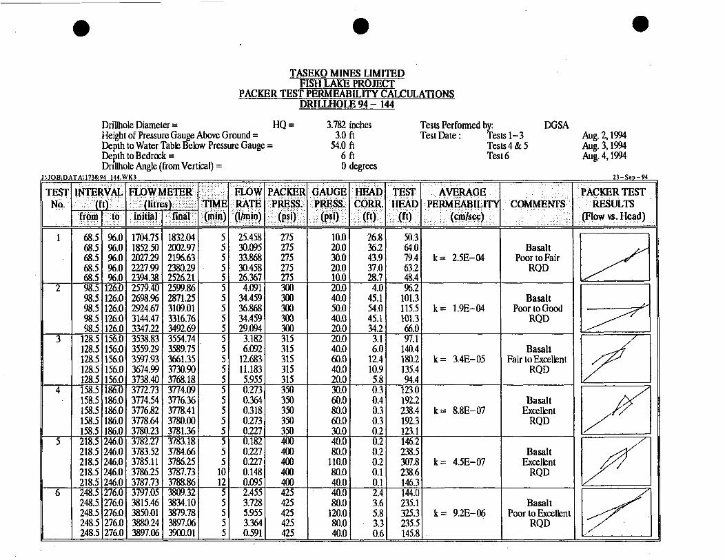
1704.75 1832.04 5 1852.50 2002.97 5 2021.29 2196.63 5 2221.99 2380.29 5 2394.38 2526.21 5 2579.40 2599.86 5 2698.% 2871.25 5 2924.67 3109.01 5 3144.47 3316.76 5 3347.22 3492.69 5 3538.83 3554.74 5 3559.29 3589.75 5 3597.93 3661.35 5 3674.99 3730.90 5 3738.40 3768.18 5 3772.73 3774.09 5 3774.54 3776.36 5 3776.82 3778.41 5 3778.64 3780.00 5
TASEKO MlNES LIMITED FISH LAKE PROJECT
PACKER TEST PERMEABILITY CALCULATIONS DRILLHOLE 94 - 144
25.458 30.095 33.868 30.458 26.367 4.091
34.459 36.868 34.459 29.094 3.182 6.092
12.683 11.183 5.955 0.273 0.364 0.318 0.273
Drillhole Diameter = HQ = 3.782 inches Tests Performed by: DGSA Height of Pressure Gauge Above Ground = 3.0 ft Test Date : Tests 1-3 Aug. 2,1994 Depth to Water Table Below Pressure Gauge = Aug. 3,1994 DeDth to Bedrock = 6ft Test 6 Aug. 4,1994
54.0 ft Tests 4 & 5
26.8 36.2 43.9 37.0 28.7 4.0
45.1 54.0 45.1 34.2 3.1 6.0
12.4 10.9 5.8 0.3 0.4 0.3 0.3
Drhhole Angle (from Vertical) =
50.3 64.0 19.4 63.2 48.4 %.2
101.3 115.5 101.3 66.0 97.1
140.4 180.2 135.4 94.4
123.0 192.2 238.4 1a.3
0 degrees
Basalt Poor to Fair
RQD
Basalt
- VAL
to
96.0 %.O %.O %.O %.O
126.0 126.0 126.0 126.0 126.0 156.0 156.0 156.0 156.0 156.0 186.0 186.0 186.0 186.0 186.0 246.0 246.0 246.0 246.0 246.0 276.0 276.0 276.0 276.0 276.0
I) - -
-
-
-
- -
E I
1
2
3
4
5
6
3780.231 3781.361 3782.27 3783.18 3783.52 3784.66 0.227 3785.1 1 3786.25 0.227
68.5 68.5 68.5 68.5 68.5 98.5 98.5 98.5 98.5 98.5
128.5 128.5 128.5 128.5 128.5 158.5 158.5 158.5 158.5 158.5 218.5 218.5 218.5 218.5 218.5 248.5 248.5 248.5 248.5 248.5
,3786.25 I 3787.73 I 10 I 0.148 3787.73 I 3788.86 I 12 I 0.095 3797.05 I 3809.32 I 5 I 2.455
3880.24 3897.06 3897.06 3900.01 0.591
275 275 275 275 275 300 300 300 300 300 315 315 315 315 315 350 350 350 350
10.0 20.0 30.0 20.0 10.0 20.0 40.0 50.0 40.0 20.0 20.0 40.0 60.0 40.0 20.0 30.0 60.0 80.0 60.0 4g-p
400 110.0 400 I 80.0
425 425 425 425
80.0 120.0 80.0 40.0
k = 2.5E-04
k = 1.9E-04
k = 3.4E-05
k = 8.8E-07
0.2 I 123.1 I 0.2 I 146.21
::; 1 g:il k = 4.5E-07 0.1 238.6 0.1 I 146.3) 2.41 144.01 3.6 I 235.1
0.6 I 145.8
k = 9.2E-06
Poor to Good RQD 1
Fair to Excellent RQD
Basalt Excellent
RQD
Basalt Excellent
RQD
Gn' Poor to Excellent
RQD

TASEKO MINES LIMITED FISH LAKE PROJECT
PACKER TEST PERMEABILITY CALCULATIONS DRILLHOLE 94 - 144
278.5 278.5 308.5 308.5 308.5 308.5 308.5 338.5 338.5 338.5 338.5 338.5 368.5 368.5 368.5 368.5 368.5 413.5 413.5 413.5 413.5 413.5
Drillhole Diameter = HQ = 3.782 inches Tests Perfonned by: DGSA' Height of Pressure Gauge Above Ground = 3.0 ft Test Date : Tests 7 & 8 Aug. 4,1994
Aug. 5,1994 Tests 9,lO & 11
306.0 306.0 336.0 336.0 336.0 336.0 336.0 366.0 366.0 366.0 366.0 366.0 411.0 411.0 411.0 411.0 411.0 436.0 436.0 436.0 436.0 436.0
De6th to Water Table Below Pressure Gauge = 54.0 ft
3923.65 3928.54 3930.59 3934.79 3942.29 3957.97 3%3.66 4220.28 4223.46 4231.64 4248.24 4254.37 4257.78 4261.42 4268.69 4278.70 4283.70 4287.79 4290.06 4292.22 4294.61 42%.31
Y
Debth to Bedrock = Drillhole Angle (from Vertical) =
3928.20 3930.13 3933.43 3940.47 3957.07 3%3.43 3%5.36 4222.55 4228.92 4246.65 4253.24 4256.65 4260.28 4265.51 4277.33 4283.13 4286.65 4289.61 4291.99 4294.49 42%.20 4297.79
0.4 0.2 0.6 1.1 2.9 1.1 0.3 0.4 1.1 2.9 1.0 0.4 0.5 0.8 1.7 0.9 0.6 0.4 0.4 0.4 0.3 0.3
K3
284.5 238.6 168.9 283.8 397.5 283.9 169.1 169.0 283.9 397.5 284.0 192.1 169.0 284.1 329.4 284.1 168.9 146.0 215.3 284.5 215.4 146.1
Basalt Poor to Good
RQD
6 f t 0 degrees
Fl 1.727 140.0
100.0
' 5 5 5 5
101 0.1591 460 I 80.0 51 0.5681 485 I 50.0
0.386 530 70.0 0.455 530 100.0 0.318 530 70.0 0.295 530 40.0
5 1.137 485 100.0 2.955 150.0 :I 1.09ll :: I 100.0
51 0.3411 485 1 50.0 51 0.4551 515 I 50.0
100.0 3.000 150.0
51 0.4551 515 I 60.0 5 I 0.5001 510 I 50.0 5 0.818 510 100.0
5 0.886 100.0 51 1.7271 :;; 1 120.0
51 0.5911 510 I 50.0 51 0.3641 530 I 40.0
k = 7.7E-07
k = 1.8E-06
k = 1.7E-06
k = 1.2E-06
k = 1.OE-06
Basalt,Sandston Conglomerate Very Poor RQD
Argillite Very Poor to Fair
RQD
V I
Gk m

EAhhllllGHEAeeERMEABlLlTYTESTUSlNG.M~QP DBLbbHQLs 94-144
of Test Interval = ater Level at Start of Test, Ho = 66.6 ft, 20.30 m
0 39 59
200
20.3 21.80 22.41 25.57
1 .oo 0.82 0.75 0.37
Notes: Falling Head Test carried out in monitoring well completion zone.
0
Time T, when (H-hMH-Ho) =
100
200 min
t I-
200 Elapsed Time (min)
~-
_ _ - - . . . . . . . . . . . . . . . . . . . . . . . . .
300
LPermeability, k = 7.6E-07 cmlsec 10:31 AM 14-NOV-94

TASEKO MINES LIMITED FISH LAKE PROJECT
PACKER TEST PERMEABILITY CALCULATIONS DRILLHOLE 94 - 147
Drillhole Diameter = HQ = Height of Pressure Gauge Above Ground = Depth to Water Table Below Pressure Gauge = Depth to Bedrock = Drillhole Angle (from Vertical) =
4 141.W -
56.0 56.0 56.0 56.0 56.0
256.0 256.0 256.0 256.0 256.0 286.0 286.0 286.0 286.0 286.0 31 1.0 31 1.0 311.0 31 1 .O 311.0
4305.97 4312.11 5 4313.47 4330.52 5 4332.57 4355.52 5 4356.89 4367.23 5
5
672.08 903.11 5 954.11 1235.15
1285.15 I 1380.17 I :
1.227 3.409 4.591 2.068 0.186 3.360
11.891 20.762 17.662 12.542 7.641
46.206 56.207 47.506 21.703 3.370
1596.99 1625.60 5 5.721 1653.20 1686.70 5 6.701 1690.80 1705.60 5 2.960 1714.26 1723.96 5 1.940
3.782 inches Tests Performed by: DGSA 2.0 ft Test Date : Tests 1 2 & 3 Aug. 8,1994 4.0 ft Tests 8,9 & 10 Aug. 10,1994 16 ft 0 degrees
15.0 230 10.0 230 5.0 400 30.0 400 60.0 400 100.0 400 60.0 400 30.0 450 30.0 450 60.0 450 100.0 450 60.0
475 60.0 475 100.0 475 60.0 475 30.0
I
1.2 14.3 3.3 23.8 4.5 34.2 2.0 25.1 0.2 15.4 3.3 70.0
11.6 130.9 20.3 214.6 17.3 125.3 12.3 61.0 7.5 65.8
2::; I 10.5 70.0
139.7 71.4
k = 6.3E-05
k = 4.8E-05
k = 6.28-05 NIA NIA NIA
k = l.lE-03
k = 1.5E-05
Basalt Fair to Good
RQD
Glaciolacust rine Sediments ,Sand, Conglomerate
~
Anomalous Result
Basalt and Conglomerate Poor to Good
RQD
23 -Sep-94
Note : Different Flow Meter Used for Tests8 to 10.

ill Rod Stick-up = 0.0 ft, 0.00 m 3.90 m ter Level at Start of Test, Ho = 12.8 ft,
Elapsed Time (min)
0 60
Val. L - - 24.5 ft. 7.5 m best Performe d Bv: DGSA
Water Depth, h (H-h)/(H-Ho) (metres)
3.90 1 .oo 3.88 0.99
Notes:
1.0 I 0.9 0.8
0.7
0.6
0.6
n 0.4 f 0.37 I v
3 0.3 E
0.2
0.1 0 50 100 150
Elapsed Time (min)
Time T, when (H-h)/(H-Ho)= 11,000 min
200
Permeability, k = 1.2E-07 cm/sec 05:OZ PM 10-Now94

ater Level a t Start of Test, Ho =
1.0 fa 0.9 0.8
0.7
0.6
0.5
n 0.4 0 0.37 f E f 3 3; 0.3
0.2
0.1
-
___
___
____
___ .......___._....
-
--
100 200 300 400 500 Elapsed Time (min)
Time T, when (H-hMH-Ho) = 11,000 min
brmeability, k = 1.2E-07 cm/sec ] 0503 PM 1O.Nov-94

1.77 m ater Level at Start of Test, Ho = 5.8 ft,
Notes:
0 20 40 60 80 100 Elapsed Time (min)
Time T, when (H-h)/(H-Ho) =
kermeability, k =
11 000 min
1 -1 E-07 cmkec 05:13 PM IO-Nov-94

ater Level at Start of Test, Ho =
Notes;
1 .o 0.9 0.8
0.7
0.6
0.5
n 0.4 f 0.37
E f E 2 0.3
0.2
. - 1 . .
0.1 0 2 4 6
Elapsed Time (min) 8 10
Time T, when (H-h)/(H-Ho) = 8 min
permeability, k = ~ 1,&-04 cm/sec 12:53 PM 10-NOV-94

0.00 m 3.90 m
0.0 ft, 12.8 ft,
ill Rod Stick-up = ater Level at Start of Test, Ho =
Notes:
1 .o 0.9 0.8
0.7
0.6
0.6
n 0.4 0
I 5 0.37
f E 0.3
0.2
0.1 0 2 4 6 a 10
Elapsed Time (min)
Time T, when (H-h)/(H-Ho) = 3 min
LPermeability, k = 3.7E-04 cm/sec 10-Nov-84 04:23 PM

ill Rod Stick-up = 0.0 ft, 0.00 m ater Level at Start of Test, Ho = 1.80 m 5.9 ft,
1.0 0.9 0.8
0.7
0.6
0.5
n 0.4 0 0 37 T . E f E 2 0.3
- - 27.5 ft. 8.4 m best Perfarmed BV: DGSA 11
\
-
............................
-____
1 .oo 0.7 1
o . 2 i 0.1
0
Time T, when (H-h)/(H-Ho) =
~- . . . . . . . . . . . . . . . . . . . .. . . . . . . .
__
10
1 __ 'A
. . . .. . . . . . . . . . . . . . . . .. . . . .
___-
1 '*
. . . . . . . . .. . . . . . . . .. . . . . . . .
-___
Elapsed Time (min)
28 min
. kermeability, k = 4.2E-05 cm/sec
20
\
1 1
. . . .... . ... . . ... .. .... ... .
-.
05:05 PM 10-Nov-84

I I
1.0 I 0.9 0.8
0.7
0.6
0.5
n 0.4 < 0.37 > 0.3 E f E
0.2.
0.1 0
Time T, when (H-hl/(H-Ho) = 16 min
5 10 15 Elapsed Time (min)
20
05:lO PM 10-Nov-84

0
~ U - E L u U m m m - ~ m DRILLHOLE 94-148
rill Rod Diameter d = ter Level at Start of Test, Ho =
Water Depth, h (metres)
0.00 0.50 3.31 4.31
4.42
(H-h)/(H-Ho)
0.34 0.14
1 .o 0.9 0.8
0.7
0.6
0.6
n 0.4 f 0.37 z E 3 O3
0.2
0.1 0 20 40 60 80 100 120
Elapsed Time (rnin)
Time T, when (H-h)/(H-Ho) = 5 0 min
permeability, k = 1.2E-05 cm/sec 0510 PM 10-NOv-94

J UOB\D
1
2
3
4
5
TASEKO MINES LIMITED FISH LAKE PROJECT
PACKER TEST PERMEABILITY CALCULATIONS BOREHOLE94 - 150
Borehole Diameter = HQ = 3.78 inches Height of Pressure Gauge Above Ground = Depth to Water Table Below Pressure Gauge =
2.0 ft 5.5 ft
9 ft Deoth to Bedrock = Boiehole Angle (from Vertical) = Tests Performed by: Test Date : Tests 1 - 5
18.5 46.0 1796.62 1853.67 5 11.411 215 18.5 46.0 1868.22 1950.53 5 16.462 215 18.5 46.0 1963.69 2057.05 5 18.672 215 18.5 46.0 2068.85 2138.26 5 13.882 215 18.5 I 46.0 I 2149.56 I 2201.91 I 51 10.471 I 215 38.5 I 66.0 1 2261.97 I 2363.08 I SI 20.222 I 235 38.5 1 66.0 1 2385.29 1 2519.30 1 51 26.8031 235 38.5 66.0 2540.30 2697.32 5 31.404 235 38.5 66.0 2718.33 2839.84 5 24.303 235 38.5 I 66.0 I 2852.34 I 2918.35 I 51 13.202 I 235 58.5 I 86.0 1 2915.95 I 2918.40 I 51 0.490 I 255
58.5 86.0 2936.60 2938.75 5 0.430 255 58.5 106.0 2939.68 2940.15 5 0.095 255
58.5 I 106.0 I 2948.05 I 2948.68 I 51 0.125 I 255 108.5 I 126.0 I 2950.40 I 2956.45 I SI 1.210 I 300 108.5 126.0 2957.70 2965.96 5 1.650 300 108.5 126.0 2968.06 2978.11 5 2.010 300 108.5 126.0 2979.51 2986.86 5 1.470 300 108.5 126.0 2987.46 2992.91 5 : 1.090 300
4.0 11.2 8.0 16.1
10.0 18.3 8.0 13.6
29.5
20.0 1 .o 30.0 1 1.4 20.0 0.9
0.4 i:: 1 0.7 20.0 0.3
0 degrees DGSA
Aug. 14,1994
10.4 4.5 I 4.2 I
15.7 11.1 1 28.1 I
73.3 k = 1.OE-05 50.8 50.7 I 74.1 k = 2.38-06 51-31 51.4 28.5 I 50.5 I 84.7
84.9 50.6
119.0 k = 1.5E-05 35.0 1.6 50.0 2.0 35.0 1.4 20.0 1.1
Basalt Very Poor to Pool
RQD
BasaltlConglom. Very Poor to fair
RQD
Conglomerate Very Poor
RQD
Conglomerate Very Poor
RQD
Argillite, Conglomerate
Poor RQD
23 -Sep-94

- Knight Piisold Ltd. CONSULTING ENGINEERS
APPENDIX E
GROUNDWATER MONITORING WELL COMPLETION DETAILS

KNIGHT PIESOLD LTD. C 0 N S U LTI NG EN GIN EERS
O r
1738Al
GROUNDWATER MONITORING WELL COMPLETION DETAILS
7 5
20 7j PROJECT FISH LAKE LOCATION N: E: COMPLETION DATE July 29, 7994
I -L 0 P, f 0 .c 2 a F 3 e
PROJECT No. 7 738 HOLE No. 94- 747 GROUND ELEVATION
30 700-
770-
Inferbedded dtstone and congIomerafe -
Hole diameter = ? 14.3mm (HW Casing
Bentonite sed-
2" diu. (5.08cm) Sch 40 Flush threaded riser
3/8 .. Baroid holeplug ch@s
Hole diameter = 96mm (UQ Bit)
Cement grout
Bentonite sed-
Grade 2/12 filter sand
2" diu. (5.08cm) Sch 40 010 S/otted screen .
2" diu. (5.08cm) Sch 40 threaded end cap
Bentonite sea/-
3/8 .. Baroid ho/ep/ug chps
I \ 3/8 " Baroid ho/ep/ug ch~ps
l M e c ~ a n i c a / Van Ruth plug
c y o .v Notes:
1. Upper bentonite sea4 cement grout and monument insta//ed by Taseko Mines Ltd
>
2 ----- - - e o 0 4 o o v v a 8 vovo
- vovo
s a
E0,H 62.79m (206 A'.) * 65

KNIGHT PIESOLD LTD. CONSULTING ENGINEERS
i n a ~ i GROUNDWATER MONITORING WELL
COMPLETION OETAl LS
V v v
V v d
D D O
PROJECT FISH UK€ LOCATION N: E: COMPLETION DATE Auqusf 7,7994
Im - 2m -
7 l.89m-
'II-
PROJECT No. 7 738 HOLE No. 94- 743 GROUND ELEVATION
Hole diameter = 1 14.3mm (HW Casing,
Bentonite seal-
2" diu. (5.08cm) Sch 40 Flush threaded riser Hole plugged with bentonite chips
3/s " Barold holeplug chips
Hole diameter = 96mm
ro
20
30
40
50-
60
70
- 7
2
p-
tigo- k
a
700-
rio-
720
730-
(HQ Bit)
0- 0-
- 5- -
- IO -
-
15-
- 20 -
-
F L25 - X 2 & 30 -
35 - -
40-
v v Hole plugged with bentonite chips -0-0
0-0: QVO v Bentonite seal- O O O 26.82m, 3/8 ,. Barold holeplug ch@s
V V o 0 0 2" diu. (5.08cm) Sch 40 v - v 010 Slotied screen a .
V " O o v
v . v 0 34.21m- 2" diu. (5.08~~7) Sch 40 . V v 35.3m - threaded end cap
V 26.97m Grade 2/12 filter sand 0 0 0
8 0
Bentonite seal- 3/s " Baroid holeplug chips
v e vo a v v
eve V
o V o v vovo vo v 0 0 0 U
V e 0
v . v 0
E0.H 61.26m (207 ft.)

1738. KNIGHT PIESOLD LTD. GROUNDWATER MONITORING WELL
PROJECT FISH LAK€ PROJECT No. 7 738
COMPLETION DATE Auq. 7. 7994 GROUND ELEVATION
COMPLETION DETAl LS CON SU LTI N G ENGl N EERS
LOCATION N: E: HOLE No. 94- 744
Sfickup ______ -Protective steel casing
20 -
40 -
60 -
80 -
700 - 1 < b 3 2720 -
740-
760 -
780 -
Hole diameter = 174.3mm (HW Cashg
Hole partia/& b/ocked at 73.41m, did not a/lo w placemen f of upper bentonite seal
Hole diameter = 96mm (HQ Bit)
and Grade 20/30 sand
8mm (27 da. Sch 40 threaded riser
- . v 48.78m- .. Grade /76 5hka sand C'Lane hit.")
v o
O V
V
V O
v o o .. . . 1 O V " 0 I I 1 - . 1 1 . 1
200 -
220 -
240 -
260-
Grade 2/12 E2er sand
Grade /I6 Si/ica sand
50.8mm (2") &a. Sch 40 threaded end cop
Bentonite sea/, "Pure Go/& medium bentonite chips (hole p/ugged with bentonite)
E0.H. 140.51m /461 f f - 1

KNIGHT PIESOLD LTD. CONS U LTI NG EN GI N EERS
:I O
rl
17381
GROUNDWATER MONITORING WELL COMPLETION DETAILS
40 -
60 - 21:
80 -
roo- 36 I 7
F L
X X 2120- 2 b 8
40
140-
760 - 50
180 -
60 200 -
220 - 70
PROJECT FISH LAK€ LOCATION N: E: COMPLETION DATE AUQ. 77, 7994
260c .
PROJECT No. 7 738 HOLE No. 94- 747 GROUND ELEVATION
I v o 6.40m- O vov
9 3
O O v .V
0
O0: v v o
0 0
o v ;
v v V
v v V
v v V
0 0 V V
O V O vo; 0
I U " - v ' U E0.H 94.79m (317 f f . )
- 0 -
- - +- +-=
+-- L
+--I- - - 61.90m- - --I- + -- - + +-+ - -
W P V C +cap
= 114.3mm (HW Casing
Hole diameter = 96mm (HQ Bit)
8mm (27 da. Sch 40 Flush threaded riser
c
4 -Open hole
Bentonite sea4 "Pure Gold"
50.Bmm (27 du. Sch 40 = medium bentonite chips .. .. T o 1 0 Slotted screen
Grade #I6 Shka sand ("Lane Mt.7
v .
50.Bmm (27 du. Sch 40 threaded end cap
medium bentonite ch@s (hole pluqed with bentonite]
300
. - _ .

KNIGHT PIESOLD LTD. CONSULTING ENGINEERS
1738.A
GROUNDWATER MONITORING WELL COMPLETION DETAl LS
PROJECT FISH LAKE
COMPLETION DATE Auq. 73, 7994 LOCATION N: E:
Pro feciive siee/ casing
Sfickup ______
nionife sea/, "Pure Go/& medium ben fonife p/ugs Hole caved in afier casing moved Casing /eft in ho/e. Hole diameier = I 14.3mm
Grude 20/30 filfer sand
Hole caved in und Mocked offer remove/ of rods, over eniire /engih or /oca/k, 3 h g s f16 fi/fer Sand and I bag 20/30 FXer Sand addec
Hole diumeier = 96mm
(HW Casing,
ro -
(HQ Bif)
75 - 2" diu. (5.08cm) Sch 40 Soha PVC riser
2" diu. (5.08cm) Sch 40 010 S/oifed screen
a .
20 -
2" diu. (5.08cm) Sch 40 threaded end cap
Hole caved in offer removd of rods
Grade f16 Sihka sand
Benfonife sea4 "Pure Goid" medium ben fonite p/ugs ,E OmH. 2g-26m
(96 ff.) 30 -
PROJECT No. 7 738
GROUND ELEVATION HOLE No. 94- 748
ro-
20
30
40
50 1
2 2 60- a 70
80
90
700-
07
-
-
-
-
-
-
-

KNIGHT PIESOLD LTD. CONSULTING E NGI N EERS
Hole diamefer = 114.3mm (HW Casing
Bentonite sea4 "Pure Gold" medium bentonite plugs
"Tafge f "/grade 2/12 filter
"Targe f "/grade 2/12 filter
2" diu. (5.08cm) Sch 40 Soha PVC riser
2" diu. (5.08cm) Sch 40 010 SIoffed screen
2" do. (5.08cm) Sch 40 fhreaded end cap
Bentonife sea4 "Pure Gold" medium ben fonife plugs
Hole sanded in offer rem0 vu/ of rods
. O . 0 37.27m- - - _-_ 3 2 2 l m - - - - - - - - - - - - - -- - - - -
1 7 3 8 . ~ 1 GROUNDWATER MONITORING WELL
COMPLETION DETAl LS PROJECT FISH LAK€
COMPLETION DATE AUQ. 15, 1994 LOCATION N: E:
PROJECT No. 1738
GROUND ELEVATION '
HOLE No. 94- 150


![{p .f9 ·1]](https://img.dokumen.tips/doc/110x75/627ea4fee86082525d56e3ad/p-f9-1.jpg)