Embed Size (px)
Citation preview
Basyx IPMInternet Communications Module
Installation & Setup ManualIPM-ISM Revision 8.1
03/14/2011
Global Control SolutionsGCS
Page 2
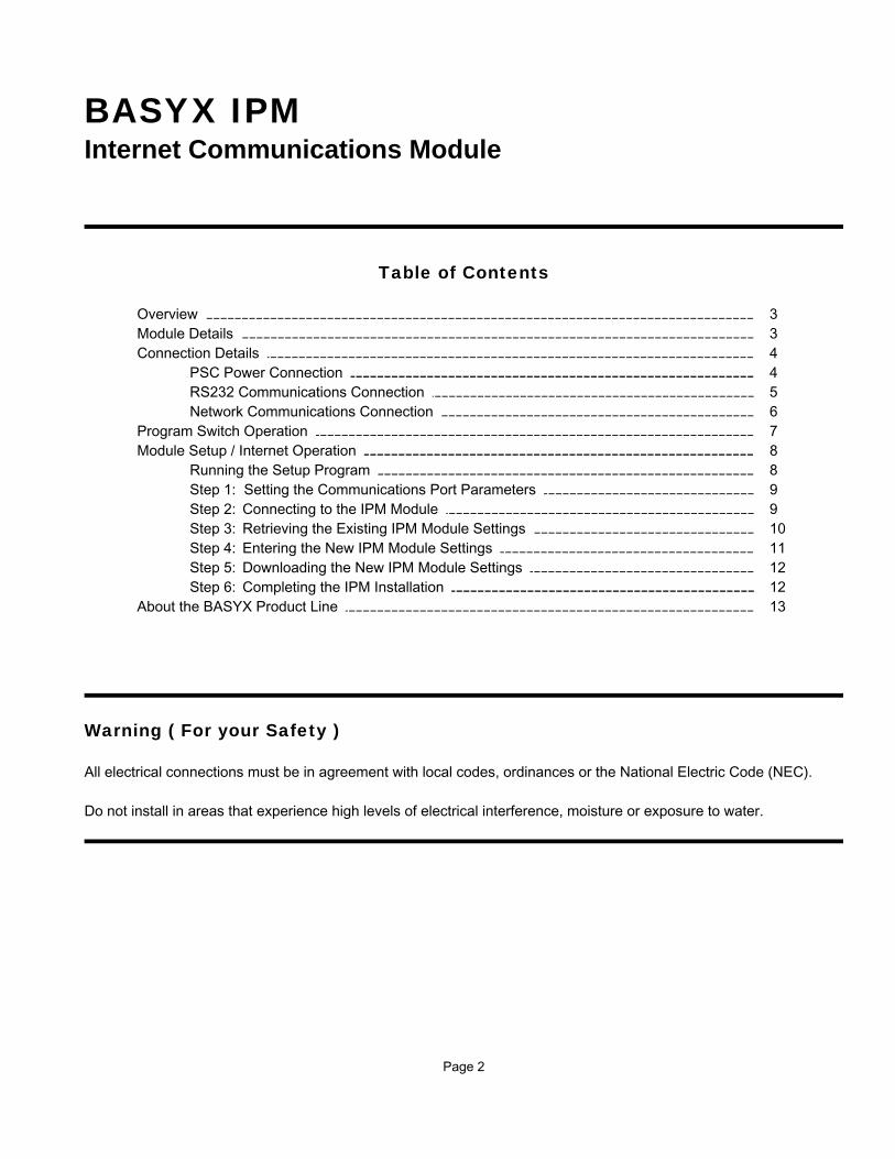
BASYX IPMInternet Communications Module
Table of Contents
Overview 3Module Details 3Connection Details 4
PSC Power Connection 4 RS232 Communications Connection 5Network Communications Connection 6
Program Switch Operation 7Module Setup / Internet Operation 8
Running the Setup Program 8Step 1: Setting the Communications Port Parameters 9Step 2: Connecting to the IPM Module 9Step 3: Retrieving the Existing IPM Module Settings 10Step 4: Entering the New IPM Module Settings 11Step 5: Downloading the New IPM Module Settings 12Step 6: Completing the IPM Installation 12
About the BASYX Product Line 13
Warning ( For your Safety )
All electrical connections must be in agreement with local codes, ordinances or the National Electric Code (NEC).
Do not install in areas that experience high levels of electrical interference, moisture or exposure to water.

Page 3
OVERVIEW
This manual describes the proper procedure for installation and connection of the Basyx Internet/Intranetcommunications module. This device performs RS232 to TCP/IP conversion for connection of the Basyx buildingautomation and temperature control system through an Internet or Intranet connection. This controller will interfacewith network systems using TCP/IP or Mac Address protocol. For IPX/SPX or other protocols, contact Global ControlSolutions technical support department. The Basyx IPM is shipped complete with mounting track for easy mounting. Please follow these instructions carefully to insure proper operation of the TCP/IP communications module.
MODULE DETAILS
Figure 1 shows the layout of the Basyx IPM module. The module contains one (1) RJ11 jack for RS-232communications, one (1) RJ45 ethernet communications jack for connection to Internet/Intranet system and one (1)position terminal for 5VDC power connection.
Figure 1: BASYX IPM Module Details
Power / CPU LED
BASYX IPM
RS232
RS485
RS4
85 IN
RS
485
OU
T+5
V-
+
-
+-
+
Program / Run Switch
PROGRAM
RUN
RJ11 Connection to PSCBoard Address #1 Only
RJ45 From Network
Not Used
Not Used
5VDC Power

Page 4
POWER / RUN LED: This is a red or green indicator light, and flashes when power is applied tothe module and the unit is in the RUN mode. The LED is on constant whenin the PROGRAM mode and will flash SLOW in Internet Mode.
PROGRAM / RUN SWITCH: This is a 3 position toggle switch which controls the program/run function ofthe controller. Move fully AWAY from the RJ11 for PROGRAM mode, andTOWARDS the RJ11 for RUN mode. The center position of theswitch is not used on the IPM module.
CONNECTION DETAILS
PSC POWER CONNECTION
Figure 2 shows the proper power connections when using a BASYX PSC controller. The IPM may also be poweredfrom separate 5vdc power supply.
Figure 2: Power Connection for PSC Controller
BASYX IPM
RS232
RS485
RS4
85 IN
RS4
85 O
UT
+5V
-
+-
+
-
+PROGRAM
RUN
PSC Board - Address #1
+ - + -REF
RS485 COMM
REF+ -1
+ -2
+ -3
+ -4
METER INPUTSIN OUT
G IN OUTG G G +5 +32
AUX POWER RS232 DIRECT
BLAC
K
RED
REDBLACK

Page 5
RS232 COMMUNICATIONS CONNECTION
The Basyx IPM must be connected to the first PSC Controller which also is addressed as #1. The connection ismade with a standard 4 conductor telephone cord (included with the BASYX IPM).
The telephone cord is plugged into the RJ11 port on the IPM module, and connects to the PSC RJ11 connectormarked “RS-232 DIRECT”.
IMPORTANT NOTE: DO NOT PLUG THIS MODULE INTO THE RJ11 MARKED “PHONE” on thePSC controller as this port is reserved for the system modem. Serious damagemay occur to the modem or IPM module if connected to the PHONE port.
Figure 3 shows the RS232 connection.
Figure 3: RS232 Communications Port Connection
BASYX PSC or 100 Board Address #1 Only
DIRECTStandard 4 conductor telephone cord
BASYX IPM
RS232
RS485
RS
485
INR
S485
OU
T+5
V-
+
-
+-
+PROGRAM
RUN

Page 6
NETWORK COMMUNICATIONS CONNECTION
This controller will interface with network systems using TCP/IP or MAC ADDRESS protocols. The Basyx IPMconnects to the network system as shown in Figure 4, and requires information from the network administrator foraddressing and connection (see Software and Module Setup section).
Figure 4: Network Connection Details
NOTE: The IPM module MUST be connected to board #1 for proper system operation.
Network Router
Standard Ethernet Cable
BASYX IPM
RS232
RS485
RS
485
INR
S48
5 O
UT
+5V
-
+-
+
-
+PROGRAM
RUN
Page 7
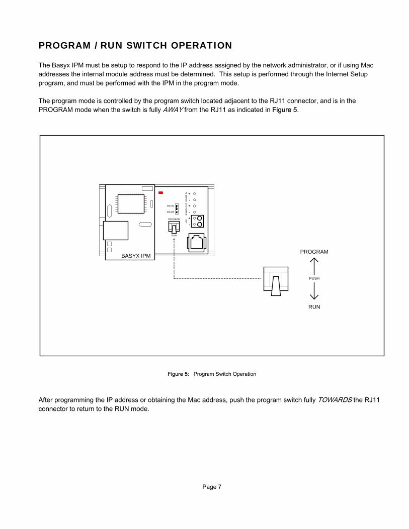
PROGRAM / RUN SWITCH OPERATION
The Basyx IPM must be setup to respond to the IP address assigned by the network administrator, or if using Macaddresses the internal module address must be determined. This setup is performed through the Internet Setupprogram, and must be performed with the IPM in the program mode.
The program mode is controlled by the program switch located adjacent to the RJ11 connector, and is in thePROGRAM mode when the switch is fully AWAY from the RJ11 as indicated in Figure 5.
Figure 5: Program Switch Operation
After programming the IP address or obtaining the Mac address, push the program switch fully TOWARDS the RJ11connector to return to the RUN mode.
PUSH
PROGRAM
RUN
BASYX IPM
RS232
RS485
RS4
85 IN
RS4
85 O
UT
+5V
-
+-
+
-
+PROGRAM
RUN

Page 8
MODULE SETUP / INTERNET OPERATION
The system is programmed through the Basyx Internet Setup software program, and connects to the module with theBCS CP cable package.
To access the TCP/IP setup program, double click the desktop shortcut icon labeled “INTERNET SETUP” or run theprogram Isetup.exe from the C:\Program Files\Triangle MicroSystems\Basyx subdirectory.
and the BASYX ISETUP opening screen will appear:
This is the opening setup screen for the IPM module, which has no data in the “Current Settings” portion of thescreen. However, data may appear in the “Default Settings” boxes from previous connections.

Page 9
STEP 1: SET THE SOFTWARE COMMUNICATIONS PARAMETERS
Make sure that the Comm Port setting is correct for your computer, and that the baud rate is set to 2400.
STEP 2: CONNECT TO THE IPM MODULE
To connect to the IPM mode, make sure the board is powered as shown in Figure 2. Connect the standard BCS CPcable directly from your PC/Laptop into the RJ11 connector on the IPM Module.
Verify that the program switch is set to the PROGRAM mode as described in Figure 5.
Hi-light and click the Connect button towards the bottom of the screen. The software will establish communicationswith the IPM board, and the screen will indicate a successful connection by displaying “Comm Port Open” in thestatus box at the bottom of the screen as shown below:
No data will appear in the “Current Settings” portion of the screen. You may see program default data in the “DefaultSettings” portion if this is not the initial setup of the board. You are now ready to retrieve any existing settings fromthe Basyx IPM.
Page 10
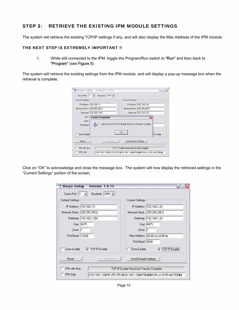
STEP 3: RETRIEVE THE EXISTING IPM MODULE SETTINGS
The system will retrieve the existing TCP/IP settings if any, and will also display the Mac Address of the IPM module.
THE NEXT STEP IS EXTREMELY IMPORTANT !!
1. While still connected to the IPM, toggle the Program/Run switch to “Run” and then back to“Program” (see Figure 5).
The system will retrieve the existing settings from the IPM module, and will display a pop-up message box when theretrieval is complete.
Click on “OK” to acknowledge and close the message box. The system will now display the retrieved settings in the“Current Settings” portion of the screen.

Page 11
STEP 4: ENTER THE NEW IPM MODULE SETTINGS
If your network requires it, the Mac Address for the IPM will be displayed at the bottom of the “Current Settings”portion of the screen. Provide your system administrator with this address for completion of the network setup.
If using a TCP/IP connection, you must change the settings to match the static TCP/IP address which is provided byyour system or network administrator.
To change the settings, place the cursor in the IP Address bar in the “Default Settings” portion of the screen.
Enter the proper information as required for your network connection (using the TAB key to move between entries):
* IP Address This must be a static IP address through your network* Network Mask See your network administrator* Gateway See your network administrator* Port This is a software port and is typically 4675 as shown, see
your network administrator if you question this port address* Zone This is not currently used and should be set to 1* Port Baud This is the PSC direct connect baud rate and should be set to 9600 for
version 1.XX PSC boards and 19200 for version 2.xx PSC Boards.* TCP/IP Enable Check this box for Internet operation (Important).
The system screen should typically appear as follows at this point:

Page 12
STEP 5: DOWNLOAD THE NEW IPM MODULE SETTINGS
Verify that the new information is correct and click on the ‘Send Default Settings” button at the bottom of the screen todownload the new settings. Once the download is completed, the screen will again display the pop-up message boxwith “Data Sent And Mac Address Received Transfer Complete” as described in Step 3. Click on “OK” toacknowledge and close the message box, and notice the status box at the bottom of the screen also indicates that thetransfer is complete. The system will now display the new settings in the “Current Settings” portion of the screen asshown:
This completes the software setup of the Basyx IPM module.
STEP 6: COMPLETING THE IPM INSTALLATION
1. Verify that the current settings are correct, and that the TCP/IP Enable box is checked.2. Connect the RJ11 port to the PSC Direct Connect Port as shown in Figure 3.3. Place the program switch in the RUN mode as shown in Figure 5 and connect to
your network as shown in Figure 4.5. Run/CPU light should flash SLOW.

Page 13
ABOUT THE BASYX PRODUCT LINE
The Basyx IPM is one product in a line of Basyx control products. The TriComm interface software package is aWindows based human interface used with the Basyx automation and control system. Tricomm will operate on anypersonal computer with the Windows 98 or later version operating system.
The program provides a simple interface through direct connect, modem or internet to setup, operate and modify theoperating parameters of the Basyx system, using easy to understand point-and-click commands. The drop-downsystem menus allow access to all system functions, and requires minimal computer experience for normal dailyinteraction with the system.
The Basyx system is designed specifically to meet today’s building automation, facility and energy managementneeds. Global Control Solutions develops and provides application support for control systems around then world. The company has a continuing commitment to research and development in order to provide new and improvedproducts to the building automation market.
For more information contact:
Global Control Solutions6307-C Angus DriveRaleigh, NC 27617
Telephone: (919) 785-2855Fax: (919) 785-2385
E-mail: [email protected]: www.globalcontrolsolutions.net
The technical contents of this document, while accurate as of publication, are subject to change without notice.No responsibility is assumed for its use.


![Demplates | Free Marketing Templates for Small …€¦ · Web view[LOGO]Studio One, 1234 Address StreetPlaceholder City, 982United KingdomTel: [numbers]Web: : yourname@website.com](https://img.dokumen.tips/doc/110x75/5fdd9eac89ed0112dc0c907f/demplates-free-marketing-templates-for-small-web-view-logostudio-one-1234-address.jpg)