Embed Size (px)
Citation preview

MA0871PHG MA0871PHG
Version 1.07 (2015.02.25)
Original instructions
INSTRUCTION MANUAL
FG-L / FG-V type Finger Chuck for Automotive Wheels
KITAGAWA IRON WORKS CO., LTD.
77-1 Motomachi, Fuchu, Hiroshima 726-8610 Japan
TEL +81-(0)847-40-0526
FAX +81-(0)847-45-8911
・ This instruction manual is for production engineers and maintenance
personnel in charge of operation of this product. When a beginner uses
this product, receive instructions from experienced personnel, the
distributor or our company.
・ Before installing, operating or maintaining this equipment, carefully
read this manual and the safety labels attached to the equipment.
Failure to follow these instructions and safety precautions could result
in serious injury, death, or property damage.
・ Store this manual near equipment for future reference.
・ If any questions related to safety arise about this manual, please
confirm them with the distributor or our company.
DANGER

1
Preface This manual provides detailed information about how to safely and correctly use the finger
chuck for automotive wheels (FG-L / FG-V type) for a lathe.
Before starting to use this finger chuck for automotive wheels, read this manual carefully
and always follow the instructions and warnings in "Important Safety Precautions" and
"Precautions for Use" at beginning of the manual. Failure to follow these precautions
could result in a serious accident.
Terms and Symbols Used for Safety Messages
In this manual, precautions for handling that are considered especially important are
classified and displayed as shown below depending on the damage of risk including the
seriousness of the harm that could result. Please sufficiently understand the meanings of
these terms and follow the instructions for safe operation.
Safety Alert Symbol
The triangle is the safety alert symbol used to alert you to potential safety hazards that
could result in injury or death.
Indicates a hazardous situation which, if you not avoided, will
result in death or serious injury.
Indicates a hazardous situation which, if you not avoided,
could result in death or serious injury.
Indicates a hazardous situation which, if you not avoided,
could result in minor or moderate injury.
Indicates instructions which, if not avoided, could result in
damage to the equipment or a shortened work life.

2
Liability and How to Use this Manual
This product is suitable for gripping an automotive aluminum wheel on the lathes or rotary
tables. This product is equipped with the levers to clamp the automotive aluminum wheel
and they operate by means of a rotary cylinder. For any other applications, please contact
us.
Our company will not assume responsibility for injury, death, damage, or loss resulting from
not following the instructions in this manual.
There are countless things that cannot or should not be done, and it is impossible to cover
all of them in this manual.
Therefore, do not perform any actions unless they are specifically allowed in this manual. If
any questions related to safety arise about operation, control, inspection and maintenance
which are not specified in this manual, please confirm them with our company or distributor
before performing them.
Guarantee and Limitation of Liability
The guarantee period of this product is 1 year after delivery.
Use the parts delivered by Kitagawa Iron Works for all the parts including consumable parts.
We will not assume responsibility for injury, death, damage, or loss caused by usage of
parts not manufactured by Kitagawa Iron Works. Additionally, if parts other than genuine
parts manufactured by Kitagawa Iron Works are used, this guarantee will be completely
invalid.
The chuck and cylinder from Kitagawa Iron Works should be used together. If you must use
a part not made by Kitagawa, check with us or our distributor to be sure it is safe to do so.
We will not be responsible for injury, death, damage or loss caused by use of a chuck or
cylinder made by another company unless this use has been approved by Kitagawa or its
distributor.

3
Table of Contents
1. Structural Drawing and Parts List -----------------------------------------------------------------------4
1-1. Type display
1-2. Structural drawing
1-3. Scope of product
1-4. Parts list
2. Important Safety Precautions ------------------------------------------------------------9
3. Specifications ----------------------------------------------------------------------------------------------14
3-1. Specifications
4. Top tooling --------------------------------------------------------------------------------------------------16
4-1. Exchange of jaw
4-2. Exchange of lever
4-3. Centering jigs
4-4. Balance pins for seating confirmation
5. Usage --------------------------------------------------------------------------------------------------------21
5-1. Precautions during gripping work with chuck
5-2. Precautions related to processing
6. Maintenance and Inspection ---------------------------------------------------------------------------23
6-1. Periodic Inspection
6-2. Grease lubrication
6-3. Disassembling
7. Malfunction and Countermeasures ------------------------------------------------------------------29
7-1. In the case of malfunction
7-2. Where to contact in the case of malfunction
For Machine Tool Manufacturers (Chapter 8)
8. Attachment -------------------------------------------------------------------------------------------------31
8-1. Outline drawing of attachment
8-2. Design of chuck open/close hydraulic circuit
8-3. Design of seating confirmation air circuit
8-4. Design of the draw pipe
8-5. Attachment of chuck
9. Other Information ----------------------------------------------------------------------------------------39
9-1. About disposal

4
1. Structural Drawing and Parts List
1-1. Type display
Type display as shown below
Fig.1

5
1-2. Structural drawing
Fig.2

6
1-3. Scope of product
This instruction manual is for the chuck part.
Fig.3
・ To prevent the work from flying, safe design, maintenance and erroneous
action prevention of the hydraulic system to maintain the gripping force of the
chuck is extremely important. Thoroughly read the “Important Safety
Precautions” on and after page 9 in this manual.
・ As for the cylinder, follow the instruction manual for the cylinder.
7
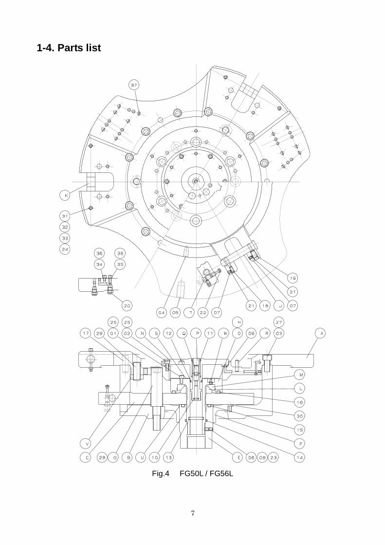
1-4. Parts list
Fig.4 FG50L / FG56L
8
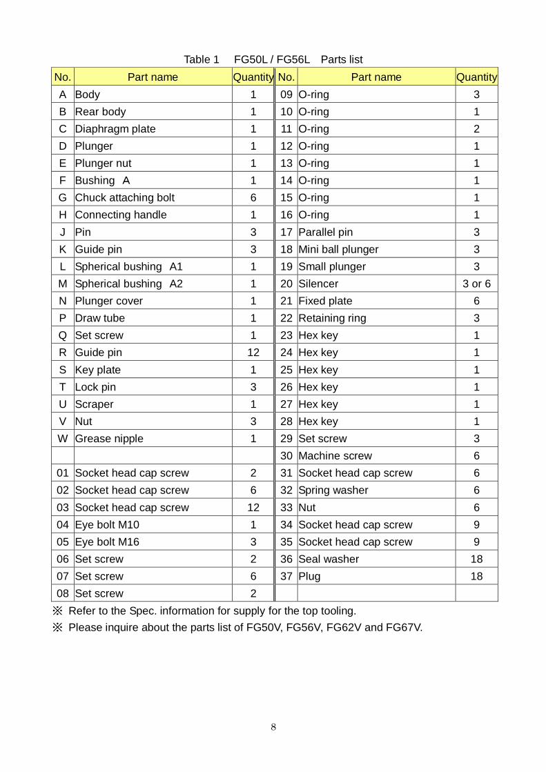
Table 1 FG50L / FG56L Parts list
No. Part name Quantity No. Part name Quantity
A Body 1 09 O-ring 3
B Rear body 1 10 O-ring 1
C Diaphragm plate 1 11 O-ring 2
D Plunger 1 12 O-ring 1
E Plunger nut 1 13 O-ring 1
F Bushing A 1 14 O-ring 1
G Chuck attaching bolt 6 15 O-ring 1
H Connecting handle 1 16 O-ring 1
J Pin 3 17 Parallel pin 3
K Guide pin 3 18 Mini ball plunger 3
L Spherical bushing A1 1 19 Small plunger 3
M Spherical bushing A2 1 20 Silencer 3 or 6
N Plunger cover 1 21 Fixed plate 6
P Draw tube 1 22 Retaining ring 3
Q Set screw 1 23 Hex key 1
R Guide pin 12 24 Hex key 1
S Key plate 1 25 Hex key 1
T Lock pin 3 26 Hex key 1
U Scraper 1 27 Hex key 1
V Nut 3 28 Hex key 1
W Grease nipple 1 29 Set screw 3
30 Machine screw 6
01 Socket head cap screw 2 31 Socket head cap screw 6
02 Socket head cap screw 6 32 Spring washer 6
03 Socket head cap screw 12 33 Nut 6
04 Eye bolt M10 1 34 Socket head cap screw 9
05 Eye bolt M16 3 35 Socket head cap screw 9
06 Set screw 2 36 Seal washer 18
07 Set screw 6 37 Plug 18
08 Set screw 2
※ Refer to the Spec. information for supply for the top tooling.
※ Please inquire about the parts list of FG50V, FG56V, FG62V and FG67V.

9
2. Important Safety Precautions
Important safety precautions are summarized below. Please read this section before first
starting to use this product.
DANGER Failure to follow the safety precautions below will result in
serious injury or death.
Turn off main power supply before attaching, inspecting or replacing
chuck, and before adding oil.
・ The chuck may start rotation
suddenly, and a part of the body or
clothing may be caught.
Close door before rotating spindle.
・ If the door is not closed, you may touch
the rotating chuck or the work may fly out,
which is very dangerous. (In general, the
safety interlock function which allows
rotation only when the door is the manual
mode or the test mode)
During spindle rotation, do not turn off hydraulic pump power supply and
do not operate switching valve.
・ Cutting off hydraulic pressure causes a drop in the gripping force which could result in
the work being released and flying out.
・ Operating the manual switching valve or solenoid valve will lead to a drop of hydraulic
pressure.
For All Users
For All Users
For All Users
10
Important Safety Precautions
DANGER Failure to follow the safety precautions below will result in
serious injury or death.
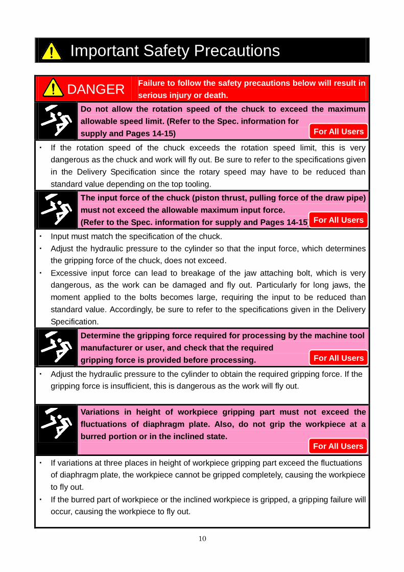
Do not allow the rotation speed of the chuck to exceed the maximum
allowable speed limit. (Refer to the Spec. information for
supply and Pages 14-15)
・ If the rotation speed of the chuck exceeds the rotation speed limit, this is very
dangerous as the chuck and work will fly out. Be sure to refer to the specifications given
in the Delivery Specification since the rotary speed may have to be reduced than
standard value depending on the top tooling.
The input force of the chuck (piston thrust, pulling force of the draw pipe)
must not exceed the allowable maximum input force.
(Refer to the Spec. information for supply and Pages 14-15)
・ Input must match the specification of the chuck.
・ Adjust the hydraulic pressure to the cylinder so that the input force, which determines
the gripping force of the chuck, does not exceed.
・ Excessive input force can lead to breakage of the jaw attaching bolt, which is very
dangerous, as the work can be damaged and fly out. Particularly for long jaws, the
moment applied to the bolts becomes large, requiring the input to be reduced than
standard value. Accordingly, be sure to refer to the specifications given in the Delivery
Specification.
Determine the gripping force required for processing by the machine tool
manufacturer or user, and check that the required
gripping force is provided before processing.
・ Adjust the hydraulic pressure to the cylinder to obtain the required gripping force. If the
gripping force is insufficient, this is dangerous as the work will fly out.
Variations in height of workpiece gripping part must not exceed the
fluctuations of diaphragm plate. Also, do not grip the workpiece at a
burred portion or in the inclined state.
・ If variations at three places in height of workpiece gripping part exceed the fluctuations
of diaphragm plate, the workpiece cannot be gripped completely, causing the workpiece
to fly out.
・ If the burred part of workpiece or the inclined workpiece is gripped, a gripping failure will
occur, causing the workpiece to fly out.
For All Users
For All Users
For All Users
For All Users

11
Important Safety Precautions
DANGER Failure to follow the safety precautions below will result in
serious injury or death.
Always tighten the bolts at the specified torque. If the torque is
insufficient or excessive, the bolt will break, which is dangerous as the
chuck or work will fly out. Use the bolts attached to the chuck, and do not
use bolts other than these.
・ If the torque is insufficient or
excessive, the bolt will break, which
is dangerous as the chuck or work
will fly out.
・ Fix the lathe spindle or the chuck
when you tighten bolts. Your hand
could slip and get injury when you
work without fixing the spindle.
・ You cannot control the torque by a
hex key. You must use a torque
wrench for torque control.
・ Tightening torque is moment of force when you tighten a bolt. Tightening torque= F×L.
Specified torque for
socket head cap screw
Bolt size Tightening torque
M5 7.5 N・m
M6 13 N・m
M8 33 N・m
M10 73 N・m
M12 107 N・m
M14 171 N・m
M16 250 N・m
M20 402 N・m
For All Users

12
Important Safety Precautions
DANGER Failure to follow the safety precautions below will result in
serious injury or death.
Provide sufficient strength for the draw pipe.
Provide sufficient screw depth for the draw pipe.
Firmly tighten the draw pipe.
・ If the draw pipe break, the gripping force is instantly lost and this is dangerous as work
will fly out.
・ If the screw depth of the draw pipe is insufficient, the screw will break and the gripping
force will be lost instantly, and this is dangerous as work will fly out.
・ If the engagement of the screw of the draw pipe is loose, vibration may occur resulting
in breakage of the screw. If the screw breaks, the gripping force will be lost instantly,
which is dangerous as the work will fly out.
・ If the draw pipe is unbalanced, vibration occurs, the screw is broken and the gripping
force will be lost instantly, which is dangerous as the work will fly out.
Use a cylinder with a lock valve (safety valve, check valve) incorporated in
case of sudden hydraulic pressure drop due to blackout, malfunction of
the hydraulic pump, etc. Further, use a solenoid valve with a circuit that
retains the gripping position when no current is carried.
・ If the hydraulic pressure
suddenly drops due to blackout
or malfunction of the hydraulic
pump, etc., this is dangerous
as work will fly out.
・ Lock valve retains the hydraulic
pressure inside the cylinder
temporarily, when the hydraulic
pressure suddenly drops due
to blackout or malfunction of
the hydraulic pump, etc.
For Machine Tool Manufactures
For Machine Tool Manufactures
13
Important Safety Precautions
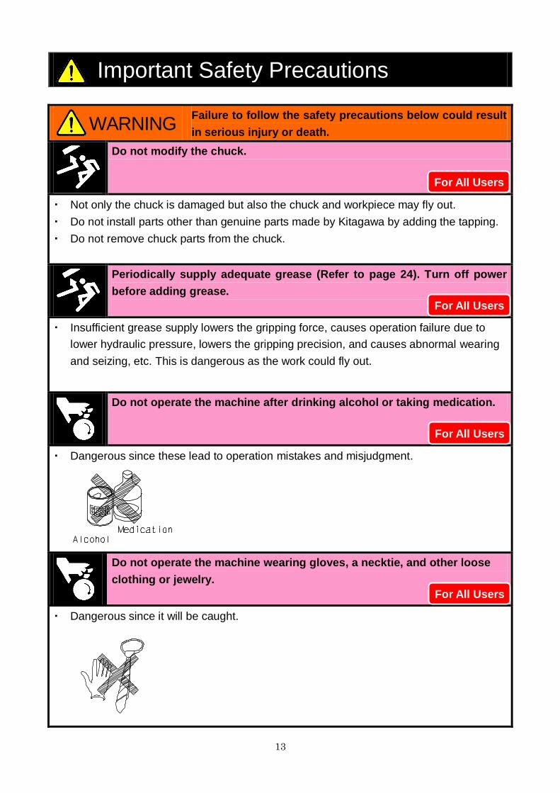
WARNING Failure to follow the safety precautions below could result
in serious injury or death.
Do not modify the chuck.
・ Not only the chuck is damaged but also the chuck and workpiece may fly out.
・ Do not install parts other than genuine parts made by Kitagawa by adding the tapping.
・ Do not remove chuck parts from the chuck.
Periodically supply adequate grease (Refer to page 24). Turn off power
before adding grease.
・ Insufficient grease supply lowers the gripping force, causes operation failure due to
lower hydraulic pressure, lowers the gripping precision, and causes abnormal wearing
and seizing, etc. This is dangerous as the work could fly out.
Do not operate the machine after drinking alcohol or taking medication.
・ Dangerous since these lead to operation mistakes and misjudgment.
Do not operate the machine wearing gloves, a necktie, and other loose
clothing or jewelry.
・ Dangerous since it will be caught.
For All Users
For All Users
For All Users
For All Users
14
3. Specifications
3-1. Specifications
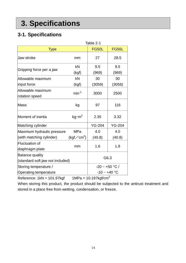
Table 2-1
Type FG50L FG56L
Jaw stroke mm 27 28.5
Gripping force per a jaw kN 9.5 9.5
(kgf) (969) (969)
Allowable maximum
input force
kN 30 30
(kgf) (3059) (3059)
Allowable maximum
rotation speed min-1 3000 2500
Mass kg 97 116
Moment of inertia kg・m2 2.35 3.32
Matching cylinder YG-204 YG-204
Maximum hydraulic pressure
(with matching cylinder)
MPa 4.0 4.0
(kgf/cm2) (40.8) (40.8)
Fluctuation of
diaphragm plate mm 1.6 1.8
Balance quality
(standard soft jaw not included) G6.3
Storing temperature /
Operating temperature
-20 ~ +50 °C /
-10 ~ +40 °C
Reference: 1kN = 101.97kgf 1MPa = 10.197kgf/cm2
When storing this product, the product should be subjected to the antirust treatment and
stored in a place free from wetting, condensation, or freeze.

15
Table 2-2
Type FG50V FG56V FG62V FG67V
Jaw stroke mm 35 35 35 35
Gripping force per a jaw kN 9.5 9.5 9.5 9.5
(kgf) (969) (969) (969) (969)
Allowable maximum
input force
kN 30 30 30 30
(kgf) (3059) (3059) (3059) (3059)
Allowable maximum
rotation speed min-1 2500 2500 2200 1500
Mass kg 130 190 190 240
Moment of inertia kg・m2 3.75 5.80 8.80 11.0
Matching cylinder YG-204 YG-204 YG-204 YG-204
Maximum hydraulic pressure
(with matching cylinder)
MPa 4.0 4.0 4.0 4.0
(kgf/cm2) (40.8) (40.8) (40.8) (40.8)
Fluctuation of
diaphragm plate mm 3.8 4.3 4.8 5.3
Balance quality
(standard soft jaw not included) G6.3
Storing temperature /
Operating temperature -20 ~ +50 °C / -10 ~ +40 °C
Reference: 1kN = 101.97kgf 1MPa = 10.197kgf/cm2
When storing this product, the product should be subjected to the antirust treatment and
stored in a place free from wetting, condensation, or freeze
・ Allowable maximum rotary speed and allowable maximum hydraulic pressure
may be different depending on the size of top tooling and workpieces. Be sure
to refer to the latest Delivery Specification to use the chuck within the given
specifications. Excessive hydraulic pressure or rotary speed will damage the
chuck, causing the chuck and workpiece to fly out.

16
4. Top tooling
4-1. Exchange of jaw
Removing the jaws
1. Loosen the set screw [1].
2. Loosen the socket head cap screw [2] and remove the jaw [3]. Save the fixed plate [4]
carefully.
Installing the jaws
1. Install the jaw [3] with the socket head cap screw [2]. At this time, the reference surfaces
of jaws and lever must contact completely. Also, tighten the socket head cap screw with
the specified torque.
2. Confirm that the fixed plate [4] is present, and then tighten the set screw [1].
Fig.5
・ Always tighten the bolts at the specified torque. If the torque is insufficient or
excessive, the bolt will break, which is dangerous as the chuck or work will fly
out.
・ Use the bolts attached to the chuck, and do not use other bolts. However, if
you must use other bolts not provided by Kitagawa, use bolts that have at
least a strength classification of 12.9 (10.9 for M22 or more) and be sure they
are long enough.
17
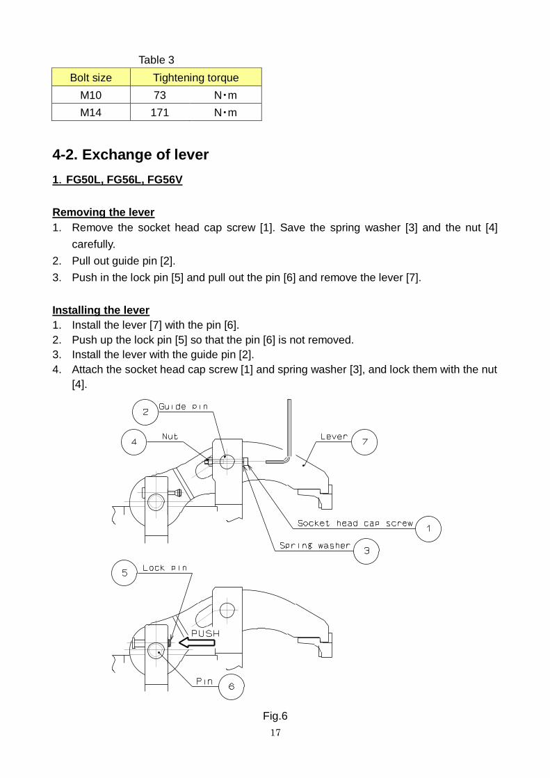
Table 3
Bolt size Tightening torque
M10 73 N・m
M14 171 N・m
4-2. Exchange of lever
1.FG50L, FG56L, FG56V
Removing the lever
1. Remove the socket head cap screw [1]. Save the spring washer [3] and the nut [4]
carefully.
2. Pull out guide pin [2].
3. Push in the lock pin [5] and pull out the pin [6] and remove the lever [7].
Installing the lever
1. Install the lever [7] with the pin [6].
2. Push up the lock pin [5] so that the pin [6] is not removed.
3. Install the lever with the guide pin [2].
4. Attach the socket head cap screw [1] and spring washer [3], and lock them with the nut
[4].
Fig.6

18
2.FG50V, FG62V, FG67V
Removing the lever
1. Remove the socket head cap screw [1]. Save the spring washer [3] and the nut [4]
carefully.
2. Pull out guide pin [2].
3. Loosen the socket head cap screw [5] and slide the plate [6] as shown in Fig.6.
4. Pull out the pin [7] and remove the lever [8].
Installing the lever
1. Install the lever [8] with the pin [7].
2. Insert the plate into the groove of pin [7] and tighten the socket head cap screw [5] so
that the pin [7] is not removed.
3. Install the lever with the guide pin [2].
4. Attach the socket head cap screw [1] and spring washer [3], and lock them with the nut
[4].
Fig.7

19
4-3. Centering jigs
Function of centering jigs
The centering jigs for workpiece is provided. They are the slide ring for process-1 or the
centering chuck / collet chuck for process-2 as shown in Fig.8. Refer to the Spec.
information for supply for the shape and specifications.
Fig.8
Do not operate the collet chuck without the work-piece or the master ring. This may
cause the collet to be damaged.

20
4-4. Balance pins for seating confirmation
Function of balance pin
For the FG-L and FG-V chucks, the balance pins for seating confirmation can be provided
at three places of chuck surface.
As shown in Fig.9, in no-load state, the balance pins are located in the upper position by the
built-in springs and the air supplied into the balance pins is exhausted outside the chuck via
the silencers. If a workpiece is gripped, the balance pins lower and the air circuit is closed
and the air pressure rises. This pressure variation is detected by the pressure switch on the
machine side.
If even one balance pin among three places is out of the workpiece, the air pressure does
not rise.
Since general balance pins cover two or more workpiece sizes, the installation position can
be changed. Refer to the Spec. information for supply for the shape and specifications.
The pressure switch will always become detected state if the balance pins remain in the
lower position due to the spring damage or sticking of chips or if the air is not exhausted
outside the chuck due to the clogged silencers. Check the balance pins periodically and
repair or replace as necessary.
Fig.9
21
5. Usage
This product is a device to fix an automotive aluminum wheel when it is processed by the
lathe machine or the rotary table.
The rotary cylinder closes the levers and fixes an automotive aluminum wheel so that it
does not move during processing. The chuck opens the lever after having processed it and
remove a wheel.
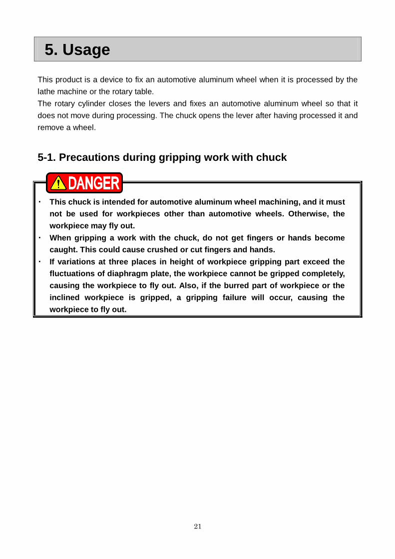
5-1. Precautions during gripping work with chuck
・ This chuck is intended for automotive aluminum wheel machining, and it must
not be used for workpieces other than automotive wheels. Otherwise, the
workpiece may fly out.
・ When gripping a work with the chuck, do not get fingers or hands become
caught. This could cause crushed or cut fingers and hands.
・ If variations at three places in height of workpiece gripping part exceed the
fluctuations of diaphragm plate, the workpiece cannot be gripped completely,
causing the workpiece to fly out. Also, if the burred part of workpiece or the
inclined workpiece is gripped, a gripping failure will occur, causing the
workpiece to fly out.

22
5-2. Precautions related to processing
<1> Unbalance
・ In the case of processing largely unbalanced work, lower the rotation speed.
The work will fly out and this is dangerous.
・ Vibrations are generated if there is unbalance owing to the work or the jig, etc.
Vibration not only will impart a negative influence on the process precision
but also the endurance of the chuck being remarkably shortened, and the
chuck may break. Correct the unbalance using balance weights, etc., or lower
the rotation speed for use.
・ Heavy cutting at high rotation speed easily generates vibration in the same
manner as chuck unbalance, therefore, set cutting conditions appropriate for
the dynamic gripping force and machine rigidity.
<2> Interference, contact, impact
・ Before starting work, check that the levers, fixed jigs, work, etc., and the tool
and the tool post, etc., do not interfere at low rotation and then start
processing.
・ Do not allow anything to impact the chuck, lever, and the work. The chuck will
break and this is dangerous as the chuck and work will fly out.
・ If the tool and the tool post contact the chuck or the work due to malfunction
or tape mistake, etc., and impact is given, immediately stop the rotation, and
check that there are no abnormalities in the body, lever, diaphragm plate and
bolts of each part, etc.
<3> Coolant
・ Unless coolant with a rust preventive effect is used, rust will occur inside the
chuck and gripping force drop may result. The work will fly out due to the
gripping force drop and this is dangerous.

23
6. Maintenance and Inspection
6-1. Periodic Inspection
Daily check
・ Remove chips from the guide groove of the lever.
・ Check that the balance pins and floating move over their stroke normally. If not smooth
or if they do not move, disassemble and clean the chuck.
・ Replace the pad pieces when worn out.
・ If the slide ring (centering jig in process 1) is used, supply grease from the grease
nipple.
・ If the centering chuck (centering jig in process 2) is used, supply grease from the grease
nipple on the side surface. Also, check that the specified stroke is obtained. In case of a
short stroke, not smooth motion, or no movement at all, disassemble and clean the
chuck.
・ Supply oil to the lubricator installed in the air piping system so as to maintain proper oil
level range. Use the turbine oil class 1 additive free (ISO VG32).
・ Check for water in the air filter of the air unit and drain it periodically, which otherwise
causes rust.
Monthly check
・ With a workpiece not gripped, check if the air is exhausted from the silencer for balance
pin. If the seating pressure rises even though the workpiece is not gripped, the silencer
may be clogged. Replace the silencer.
3-month check
・ Check if the specified stroke is obtained when the chuck is moved over the stroke.
Remove the centering jig in the center of chuck and check the stroke at the top surface
of the plunger. If the stroke is short, chips may accumulate inside the lever or chuck, or
chuck internal parts may be damaged. Disassemble and clean the chuck.
・ Check if the chuck mounting bolts and jaw mounting bolts are loose.
・ Supply grease from the grease nipple on the top surface of the plunger.
Check every 6 months or 100-thousand strokes
・ Disassemble the chuck main body or balance pin assembly, floating assembly, etc. to
check respective parts for a crack or damage using the color check, and repair or
replace as necessary. Also, replace the O-rings and seals as necessary.

24
6-2. Grease lubrication
1. Position to lubricate
・ Slide ring (Centering jig for process-1)
・ Body periphery part of centering chuck (Centering jig for process-2)
・ Plunger top surface
2. Grease to use
・ Use the designated grease specified in Table 4. If grease other than the designated
grease is used, sufficient effect may not be obtained.
Table 4
Genuine
product CHUCK GREASE PRO
Kitagawa genuine product
(Kitagawa distributor of each country)
Conventional
product
Kitagawa chuck grease Conventional product
Molykote EP Grease TORAY Dow Corning (only inside Japan)
Chuck EEZ grease Kitagawa-Northtech Inc. (North American region)
MOLYKOTE TP-42 Dow Corning (Europe, Asian region)
Kluberpaste ME31-52 Kluber lubrication (worldwide)
3. Frequency of lubrication
Supply grease to the grease nipple on the top surface of the plunger every 3 months. For
other grease nipples, supply grease every day.

25
4. Safety information about grease and anti-rust oil
Applicable range
・ Designated grease
・ Antirust agent applied to the product at the delivery.
First aid measures
After inhalation: Remove victim to fresh air. If symptoms persist, call a physician.
After contact with skin: Wash off with mild cleaners and plenty of water. If symptoms persist,
call a physician.
After contact with eyes: Rinse with plenty of water. If symptoms persist, call a physician.
After ingestion: If large amounts are swallowed, do not induce vomiting. Obtain medical
attention.
・ Please refer to each MSDS about the grease and the anti-rust oil which you prepared.

26
6-3. Disassembling
Disassembling procedures
Read the following disassembling procedures with reference to pages 7-8.
1. Before start of work, be sure to turn off the main power of the machine. Also, start work
with the pistons located in the forward end position.
2. Remove the levers, balance pins and centering jig in advance.
3. Loosen the socket head cap screw [02] and remove plunger cover [N].
4. Loosen the socket head cap screw [01] and remove the key plate [S].
5. Remove the socket head cap screw [03].
6. Lift up the body [A] with an eyebolt M16 [05] and remove it while hitting the back side
with a plastic hammer.
7. Install the connecting handle [H] to the plunger [D] with the socket head cap screw [01].
8. Rotating the connecting handle [H], remove the diaphragm plate [C] together with the
plunger [D].
9. Clean respective parts and check for a crack or damage.
・ Use an eyebolt when attaching and detaching the chuck to and from the
machine, as there is a danger of injury or damage if the chuck drops.
・ Remove the eyebolt without fail after using. If the chuck is rotated with the
eyebolt, etc., attached, they may fly out and this is dangerous.
・ Disassemble and clean the chuck at least once every 6 months or every
100,000 strokes (once every 2 months or more for cutting cast metal). If
cutting powder or other substances stagnate inside the chuck, it will lead to
insufficient stroke and a drop in the gripping force, and this is dangerous as
the work will fly out. Check each part carefully and replace any part that is
worn or cracked.
・ After inspection, apply sufficient grease in the designated areas and
reassemble.
・ If you stop the machine for a long period of time, remove the work from the
machine. If you don't, the work can drop due to a drop in the hydraulic
pressure or the cylinder can stop or malfunction.
・ If you stop the machine or store the chuck for a long period of time, add
grease to prevent rust.

27
Assembling procedures
Read the following assembling procedures with reference to pages 7-8.
1. Before start of work, be sure to turn off the main power of the machine. Also, start work
with the pistons located in the forward end position.
2. Install the connecting handle [H] to the plunger [D] with the socket head cap screw [01].
3. Rotating the connecting handle [H], tighten the plunger [D] together with the diaphragm
plate [C] into the draw-pipe.
4. Install the body [A] with the socket head cap screws [03]. Adjust so that the runout of
diameter is less than 0.02 mm T.I.R. as shown in Fig.10.
5. Using the connecting handle [H], as shown in Fig.11, adjust the position of plunger [D]
and install the key plate [S] with the socket head cap screws [01]. Then, move the chuck
over full stroke to check that the specified stroke is obtained.
6. Install the plunger cover [N] with the socket head cap screws [02].
7. Install the lever, balance pins and centering jig.
・ Always tighten the bolts at the specified torque. If the torque is insufficient or
excessive, the bolt will break, which is dangerous as the chuck or work will fly
out.
・ Use the bolts attached to the chuck, and do not use other bolts. However, if
you must use other bolts not provided by Kitagawa, use bolts that have at
least a strength classification of 12.9 (10.9 for M22 or more) and be sure they
are long enough.
Table 5
Bolt size Tightening torque
M5 7.5 N・m
M6 13 N・m
M8 33 N・m
M10 73 N・m
M12 107 N・m
M14 171 N・m
M16 250 N・m
M20 402 N・m

28
Fig.10
Fig.11
Table 6
Type A
FG50L MIN 0 MAX 27
FG56L MIN –1.5 MAX 27
FG50V MIN 6 MAX 41
FG56V MIN 6 MAX 41
FG62V MIN 6 MAX 41
FG67V MIN 6 MAX 41

29
7. Malfunction and Countermeasures
7-1. In the case of malfunction
Check the points specified in the table below and take the appropriate countermeasure.
Table 7
Defective Cause Countermeasure
The chuck
does not
operate.
The chuck inside will break. Disassemble and replace the broken part.
The sliding surface is seized. Disassemble, correct the seized part with oilstone, etc., or
replace the part.
The cylinder is not operating. Check the piping and the electric system, and if there is no
abnormality, disassemble and clean the cylinder.
Insufficient
stroke of the
lever.
Chips accumulate in guide groove
of the lever. Remove the lever and clean it.
The Work
slips.
The stroke of the lever is
insufficient. Remove the lever and clean it.
The gripping force is insufficient. Check that the correct hydraulic pressure is obtained.
The cutting force is too large. Calculate the cutting force and check that it is suitable for
the specification of the chuck.
The rotation speed is too high. Slow down to appropriate rotary speed.
Precision
failure.
Centering jig or chuck body runs
out.
Check respective parts for diameter runout and end face
runout.
Contact surface of centering jig to
the workpiece has worn. Correct the centering jig or replace the parts.
The gripping force is too large
leading to the work being
deformed.
Lower the gripping force in the range possible to process to
prevent deformation.

30
・ If the chuck failed due to a seizure or breakage, remove the chuck from the
machine, following the disassembly steps in page 26. When the chuck cannot
be removed due to a blockage of workpiece, do not disassemble forcibly but
please contact us or our agent.
・ If these countermeasures do not correct the problem or improve the situation.
Immediately stop using the machine. Continuous use of a broken product or a
defective product may cause a serious accident by the chuck or the work
flying out.
・ Only experienced and trained personnel should do repairs and fix
malfunctions. Repair of a malfunction by a person who has never received
instruction from an experienced person, the distributor or our company may
cause a serious accident.
7-2. Where to contact in the case of malfunction
In the case of malfunction, contact the distributor where you purchased the product or our
branch office listed on the back cover.

31
For Machine Tool Manufactures Following pages are described for machine tool manufacturers (personnel who attach a
chuck to a machine). Please read following instruction carefully when you attach or detach
a chuck to machine, and please sufficiently understand and follow the instructions for safe
operation.
8. Attachment
8-1. Outline drawing of attachment
Fig.12

32
・ Attach the manual switching valve at a position where it is easy to operate for the
attaching equipment.
・ Install the hydraulic unit at a position where the drain hose is not kinked and the needle
of the pressure gauge is easily read.
・ When other actuators are operated by the same hydraulic pressure source as
the cylinder for chuck, be sure that a pressure drop of the cylinder does not
occur during use. A hydraulic pressure drop leads to a drop in the gripping
force which could allow the work to fly out.
・ As to the drain hose
・ Use a transparent vinyl hose for visualization.
・ Provide a stream slope, without air pocket. This will ensure no back
pressure.
・ The end of the hose is physically above the oil level. (Refer to Fig.12)
・ If the hydraulic oil stagnates inside the cylinder, oil leakage occurs, which may
cause a fire.
・ Install after removing the dust inside the pipe completely.
・ Add a filter to the pressure supply line. If foreign matters gets inside the
cylinder, this is dangerous since the rotation valve of the cylinder will seize,
the hose will tear off, and the cylinder will rotate. This is also dangerous as the
work will fly out.
・ Always use a flexible hose for the hydraulic piping to the cylinder, and the
bending force or tensile force of the pipe must not be applied to the cylinder.
Use a pipe inside diameter as large as possible and keep the piping length as
short as possible.
・ Especially, when a large sized hydraulic unit is used, excessive surge pressure is
generated and the gripping force becomes large, therefore, it may result in breakage
of the chuck or the lowering of endurance. Restrain the surge pressure by adopting
a throttle valve, etc.
33
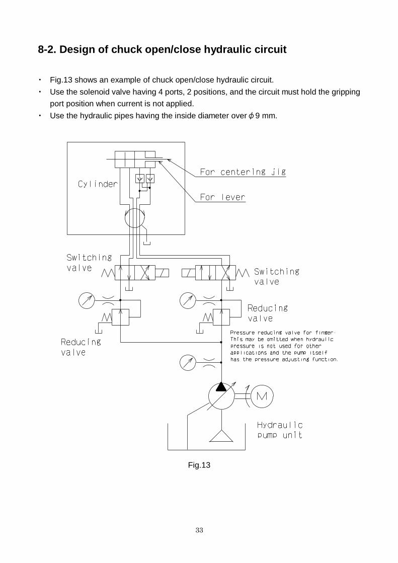
8-2. Design of chuck open/close hydraulic circuit
・ Fig.13 shows an example of chuck open/close hydraulic circuit.
・ Use the solenoid valve having 4 ports, 2 positions, and the circuit must hold the gripping
port position when current is not applied.
・ Use the hydraulic pipes having the inside diameter overφ9 mm.
Fig.13

34
8-3. Design of seating confirmation air circuit
Fig.14 shows an example of seating confirmation air circuit.
・ The solenoid valve for seating confirmation must be in detected state when current is
applied.
・ Use the air pipes having the inside diameter overφ4 mm.
Fig.14
35
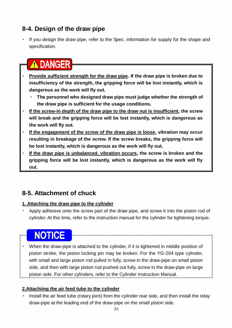
8-4. Design of the draw pipe
・ If you design the draw pipe, refer to the Spec. information for supply for the shape and
specification.
・ Provide sufficient strength for the draw pipe. If the draw pipe is broken due to
insufficiency of the strength, the gripping force will be lost instantly, which is
dangerous as the work will fly out.
・ The personnel who designed draw pipe must judge whether the strength of
the draw pipe is sufficient for the usage conditions.
・ If the screw-in depth of the draw pipe to the draw nut is insufficient, the screw
will break and the gripping force will be lost instantly, which is dangerous as
the work will fly out.
・ If the engagement of the screw of the draw pipe is loose, vibration may occur
resulting in breakage of the screw. If the screw breaks, the gripping force will
be lost instantly, which is dangerous as the work will fly out.
・ If the draw pipe is unbalanced, vibration occurs, the screw is broken and the
gripping force will be lost instantly, which is dangerous as the work will fly
out.
8-5. Attachment of chuck
1. Attaching the draw pipe to the cylinder
・ Apply adhesive onto the screw part of the draw pipe, and screw it into the piston rod of
cylinder. At this time, refer to the instruction manual for the cylinder for tightening torque.
・ When the draw-pipe is attached to the cylinder, if it is tightened in middle position of
piston stroke, the piston locking pin may be broken. For the YG-204 type cylinder,
with small and large piston rod pulled in fully, screw in the draw-pipe on small piston
side, and then with large piston rod pushed out fully, screw in the draw-pipe on large
piston side. For other cylinders, refer to the Cylinder Instruction Manual.
2.Attachiing the air feed tube to the cylinder
・ Install the air feed tube (rotary joint) from the cylinder rear side, and then install the relay
draw-pipe at the leading end of the draw-pipe on the small piston side.

36
3. Attach the cylinder to the spindle (or the cylinder adapter)
・ Check the run-out of the cylinder, and if it is normal, attach the hydraulic pipe.
・ Move 2 to 3 times at low pressure (0.4 MPa-0.5 MPa, 4 - 5 kgf/cm2) and set the piston at
the forward end and turn off the power supply.
・ Use an eyebolt when attaching and detaching the chuck to and from the
machine, as there is a danger of injury or damage if the chuck drops.
・ Remove the eyebolt without fail after using. If the chuck is rotated with the
eyebolt, etc., attached, they may fly out and this is dangerous.
4. Connect the chuck to the draw pipe
・ Remove the centering jig, plunger cover and key plate of the chuck, and rotate the
plunger by the connecting handle to joint the chuck to the draw-pipe.
・ When connecting the plunger and the draw pipe, do not forcibly screw them in if they
cannot be screwed smoothly, but check the inclination of the core of the screw, etc.
・ If the screw-in depth of the draw pipe to the plunger is insufficient, the screw
will break and the gripping force will be lost instantly, which will the work to fly
out.
・ If the engagement of the screw of the draw pipe is loose, vibration may occur
resulting in breakage of the screw, loss of gripping force and the work flying
out.

37
5. Attach the chuck matching to the attaching surface of the spindle (or the back
plate).
・ Turn the connecting handle to make a state that the chuck closely contacts the spindle
attaching surface of the lathe.
・ In the case of adjusting the centering of the chuck, lightly hit the body side face with a
plastic hammer.
・ Tighten the chuck attaching bolts evenly. At this time, tighten the bolts at the specified
torque.
・ Always tighten the bolts at the specified torque. If the torque is insufficient or
excessive, the bolt will break, which is dangerous as the chuck or work will fly
out.
・ Use the bolts attached to the chuck, and do not use other bolts. However, if
you must use other bolts not provided by Kitagawa, use bolts that have at
least a strength classification of 12.9 (10.9 for M22 or more) and be sure they
are long enough.
Table 8
Bolt size Tightening torque
M5 7.5 N・m
M6 13 N・m
M8 33 N・m
M10 73 N・m
M12 107 N・m
M14 171 N・m
M16 250 N・m
M20 402 N・m
6. Adjust the position of the plunger
・ Using the connecting handle, adjust the plunger position as shown in Fig.16, and then
install the key plate to lock. Table 9 indicates dimension by a standard specification. It is
sometimes different depending on the specifications, so refer to it together with a
delivery specification.
・ Move the chuck over full stroke to check that the specified stroke is obtained.
・ Install plunger cover, and adjust each part so that the runout of diameter is less than
0.02 mm T.I.R. as shown in Fig.15.

38
Fig.15
Fig.16
Table 9
Type A
FG50L MIN 0 MAX 27
FG56L MIN –3.5 MAX 25
FG50V MIN 6 MAX 41
FG56V MIN 6 MAX 41
FG62V MIN 6 MAX 41
FG67V MIN 6 MAX 41

39
9. Other information
9-1.About disposal
Ultimate disposal of this product should be handled according to all national laws and
regulations.


![Exercise 10 Hex Mesh[1]](https://img.dokumen.tips/doc/110x75/563db946550346aa9a9bc172/exercise-10-hex-mesh1.jpg)


