Embed Size (px)
Citation preview

Scored cut marks on spindle for a center positioned lock.
Installation Instructions based on centered lock orientation.The pull can be positioned above or below the center of the lock. Proceed to step 3.
1. Route door according to routing detail instructions (Pg. 2).
2. Ensure lift slide lock is installed in the door with the wheels in the up and locked position.
3. Determine spindle length requirements (fig. 2).4. Cut spindle to length. Remove and deburr any sharp
edges.5. Insert handle assembly with the operating handle in
the top (12 O’clock) position (fig. 3).
6. Drill (4) pilot holes using a 1/16” diameter drill bit, then mount with the handle with the included M4 x 20mm mounting screws.
7. Test the handle operation.
FFI PRODUCT DRAWING
©
C
B
A
D
E
1 2 3 4
B
A
C
D
E
1 2 3 4
-
For 2.67” (68mm) door panel thickness
For 2.25” (57mm) door panel thickness
Fig. 2
Fig. 3
Page 1 of 5 Copyright © 161811
* See page 4 for other door panel thicknesses and lock positions.
Installation Instructions
FFI Lift Slide Cascade LS400 Handle

Page 2 of 5 Copyright © 161811
Installation Instructions
FFI Lift Slide Cascade LS400 Handle

Page 3 of 5 Copyright © 161811
Installation Instructions
FFI Lift Slide Cascade LS400 Handle
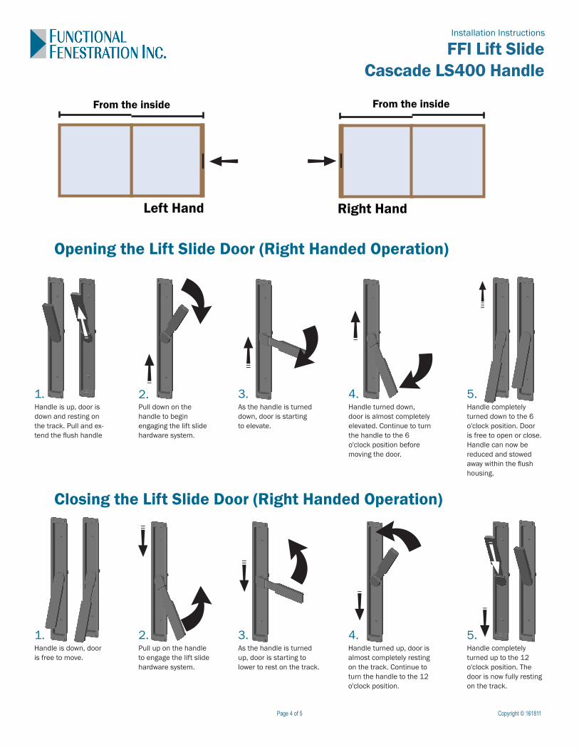
Opening the Lift Slide Door (Right Handed Operation)
Closing the Lift Slide Door (Right Handed Operation)
Left Hand Right Hand
From the insideFrom the inside
1.Handle is up, door is down and resting on the track. Pull and ex-tend the flush handle
2.Pull down on the handle to begin engaging the lift slide hardware system.
3.As the handle is turned down, door is starting to elevate.
4.Handle turned down, door is almost completely elevated. Continue to turn the handle to the 6 o'clock position before moving the door.
5.Handle completely turned down to the 6 o'clock position. Door is free to open or close. Handle can now be reduced and stowed away within the flush housing.
1.Handle is down, door is free to move.
2.Pull up on the handle to engage the lift slide hardware system.
3.As the handle is turned up, door is starting to lower to rest on the track.
4.Handle turned up, door is almost completely resting on the track. Continue to turn the handle to the 12 o'clock position.
5.Handle completely turned up to the 12 o'clock position. The door is now fully resting on the track.
Page 4 of 5 Copyright © 161811
Installation Instructions
FFI Lift Slide Cascade LS400 Handle

Page 5 of 5 Copyright © 161811
Your handle comes with score marks for a 57mm (2.25”) and 68mm (2.677”) sash thicknesses with locks that are centered in the stile related to the interior and exterior surfaces of the panel.
Some door designs are made with the lock off set from center, for these types of door designs a cut length or hole depth should be predetermined using the information below.
Option 1: Cut back spindle to proper length to maintain contact within the lock case formula:Dim A - 16mm (0.669”) = cut length
IMPORTANT
Option 2: Drill a clearance hole for extra spindle length to avoid cutting spindle. It is recommended to use a drill that will produce flat bottom. Avoid drilling too deep as not to puncture the other side of the panel. It is important your drill depth is accurate when using thinner panels.
Scored cut mark for 57mm (2.25”)panel thickness
centered lock design
Scored cut mark for 68mm (2.669”)
panel thicknesscentered lock design
65mm (2.559”)MAX offset for
lock centerfrom interior
Interior
67mm (2.638”)hole depth
Ø15.88mm (0.625”)flat bottom
72mm (2.835”)Min. panelthickness
39mm (1.535”)MIN offset for
lock centerfrom interior
17mm (0.669”)
DIM A
Spindlecut length
1mmClearance
Interior
Installation Instructions
FFI Lift Slide Cascade LS400 Handle