Embed Size (px)
Citation preview

FF - ALICE Forum 22/09/04
Meeting ALICE radiation tolerance for COTS: introduction
Some reasons for this meeting:
• A part very inner detectors (Pixels and SDD), ALICE has wide grey area; important decisions for the system depending on:
risk analysis (how much system failure can be tolerated)
economics (often parameter for ultimate decision of rad hard vs. COTS)
system architecture (system redundancy and quantization+location)
• Electronics need to be validated for installation.
safe margins
performance/cost
evaluate weak areas and probability of shut down time
• Never done ALICE survey beforeAims:
• Status of COTS electronics in ALICE
tested
planned
“overlooked”
• Regroup documents of tests already done by collaboration
improve ALICE database (knowledge)
stimulate commonalities (learn from others)
compare and conform conclusions (validate results)
• Forum for discussion

FF - ALICE Forum 22/09/04
Meeting ALICE radiation tolerance for COTS (August 30th - Room 161 1 009)
Agenda (morning):
• 10h00 - Introduction (F. Formenti - 10 min)
• 10h10 - Radiation in the ALICE environment (A. Morsch - 20 min)
• 10h30 - SSD (M. Rossewij - 20 min)
• 10h50 - TPC Front End Card (L. Musa - 20 min)
• 11h10 - TPC Readout Control Unit (D. Rohrich - 20 min)
TRD DCS Card (D. Rohrich - 15 min)
PHOS (D. Rohrich - 5 min)
• 11h50 - TOF (P. Antonioli - 20 min)
• 12h10 / 13h30 Lunch
Agenda (afternoon):
• 13h30 - Mu Arm Trk (F.F. summary - 20 min)
• 13h50 - FMD (B. Nielsen - 20 min)
• 14h10 - DAQ (C. Soos - 20 min)
• 14h30 - DCS (P. Chochula - 20 min)
• 14h50 - Trigger (P. Jovanovic - 20 min)
• 15h10 / 15h30 Coffee break
• 15h30 - Power supplies Caen (L. Periale - 20 min)
• 15h50 - Power supplies Wiener (B. Allongue - 20 min)
• 16h10 - Summary & discussion (F. Faccio & all - 40 min)
Thanks to all participants!

FF - ALICE Forum 22/09/04
Running scenarios
4.2 1015 particles produced/10years (mainly pp & ArAr high L) worst case for TID (cumulated effect)
2400 particles/event and 3 105 event/sec produced in ArAr(high) flux = 7.2 108 worst case for SEE (statistical effect) (for comparison: 1.1 108 PbPb and 2 107 pp)
Running shares pp=50%, pPb=3%, ArAr(low)=0.5%, ArAR(high)=33%, PbPb=13.5%
Other effects
2 1014 particles produced by Beam-Gas inside ALICE
8 1014 particles produced by Beam-Halo from tunnel machine
Beam loss at injection: <1% background at ITS and <3% at rack locations
~10% contribution each; ~ x2 uncertainty
NOTE: No TPC in ArAr (high)
Hyp: 10 beam loss / year
FF - ALICE Forum 22/09/04
Solenoid Mou
n di
pole
AZ
Y
Detector Dose total/10yrs [Rad] Fluence n total [cm-2] n_Ekin>20MeV Chg_h>20MeV
SPD 275k-68k 8.5 1011-6.0 1011 3.4 1011- 1.4 1011 4.0 1012-1.2 1012
SDD 25k-12k 4.9 1011-4.5 1011 3.7 1010- 2.6 1010 3.8 1011-1.3 1011
SSD 5k-3k 4.3 1011-4.2 1011 2.0 1010- 1.7 1010 5.0 1010-4.0 1010
TPC 1.6k-220 3.9 1011-2.5 1011 1.1 1010- 2.9 109 8.0 109-1.3 109
TRD 180 1.6 1011 2.0 109 7.2 108
TOF 120 1.1 1011 1.6 109 5.3 108
HMPID 50 8.6 1010 1.2 109 3.0 108
PHOS 40 8.2 1010 - -
V0 330k-230k 6.4 1011-17 1011
T0 330k-200k 5.6 1011-19 1011
FMD 135k-230k-330k 14 1011-6.5 1011-5.6 1011
PMD 26k 3.1 1011
MU TRK 500-360-100-50-40 5.6 1011-4.1 1011-1.3 1011-
0.9 1011-1.0 1011
MU TRG 260-260 2.0 1011-2.0 1011
Rack position
Dose Max/10yr [Rad]
Fluence Max [cm-2]
1MeV n-equ
A 0.94 6.7 107
B 1.3 7.0 107
C 1.2 7.2 107
D 1.1 5.3 107
E 0.61 8.6 107
F 0.66 8.1 107
G 1.4 2.0 108
H 0.72 1.1 109
I 0.38 1.1 108
J 2.6 4.3 108
K 0.74 1.2 108
L 0.31 8.3 107
M 1.2 3.0 107
B
C
D F
E
G
H I J
K L M
A
B
C D
1
1
NOTE:
Radiation for mid rapidity detectors at high radii, muon arm detectors and cavern is dominated by neutrons
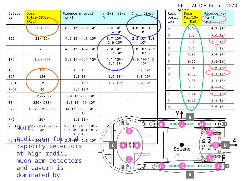
FF - ALICE Forum 22/09/04SSD detector (system)
SSD sub-detectorCTP
DAQ
DCS
Slowcontrol
FEROMsystem
L1/L2 TTC
L0 (lvds)
Busy (lvds)
DDL fiber
JTAG
CAN
ECM 110...13 x Analog
JTAG (5xlvds)
control (5xlvds)error (1xlvds)
ECM 2
ECM 144
SSD-module 1
SSD-module 10…13
…
ON-Detector electronics:
Sensor modules HAL25 chip 0.25 m rad tol. tech.
End Cap Modules Alcapone & Alabuf chips 0.25 m rad tol. tech.
Power transistors for Voltage regulation tested ( which type and results? High TID and high flux)
Rack electronics (passerelle A):
- FEROM system:
ADModules ADCs + 2xFPGAs + SRAM which types? tested for rad tol?
Link Modules FPGA which type? tested for rad tol?
- Power supply:
Planned CAEN SY1527 Not the CAEN planned configuration for rad tol.
0.25m tech: should be OK
Make tests with CAEN/ESS
FF - ALICE Forum 22/09/04
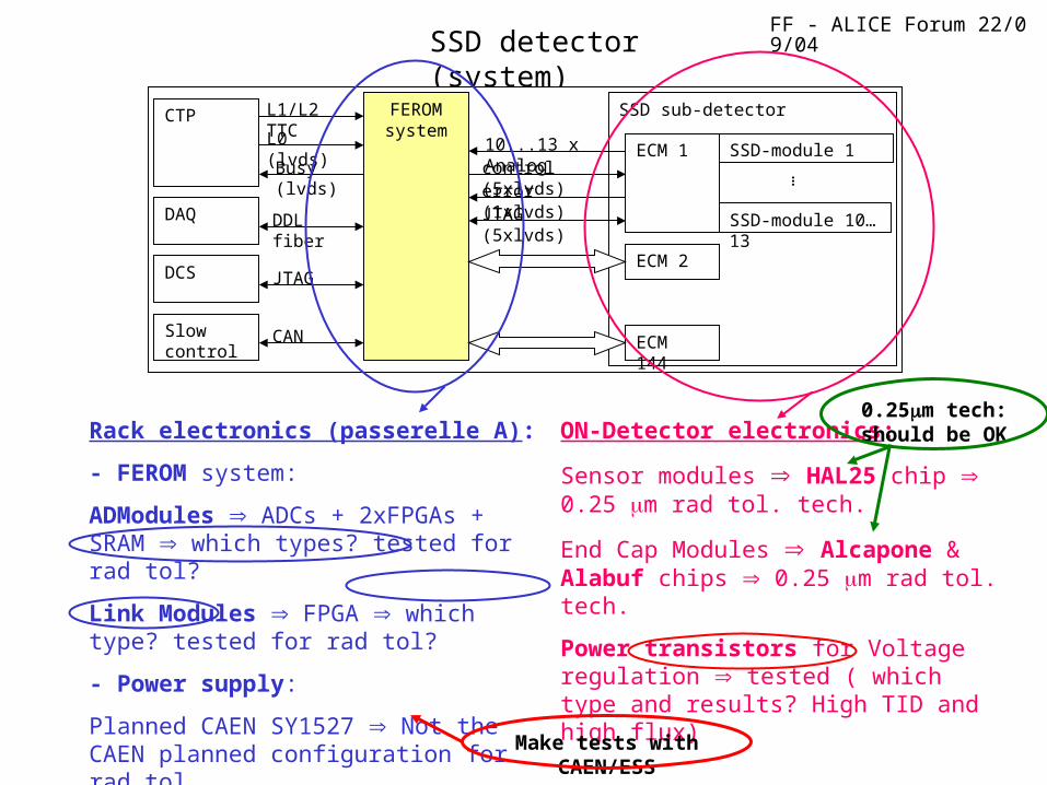
• Assumed 1MeV n-equ. fluence: 1 x 10⁸/cm2 (rack position I)• Hadron >20MeV fluence factor 10 lower: 1 x 10⁷/cm2
• Assumed running time: 107 sec.• So flux hadron >20MeV: 1/cm2.sec.
• Assumed SEU cross section for FPGA and SRAM memories 10-13 cm2/bit. (For the SRAM’s, this seems a fairly good estimate, for the FPGA’s no real data at this moment available). Also for the configuration PROM no real data available.
• Error rate using assumed cross section: 10-13/bit.sec:• 10 % of FPGA’s total config memory: 34 Mega-bits
o Error rate: 34E6x10-13= 3.4 10E-6 bits/sec. Aprox. 1 bit/ 80hrso SEU can hang-up system. o Ferom has JTAG which allows partial readback and reconfiguration
• Offset and zero suppress memory: 40 Mega-bitso Error rate: 40E6x10-13 = 4E-6 bits/sec. Aprox. 1 bit/70 hrs.o No system hang-up, SEU detected by readback after every run
• Event data memory: 14 Mega-bits (5% occupancy, All 4MEB in use)
o Error rate: 14E6x10-13 = 14E-7 bits/sec. Aprox. 1 bit/200 hrs.o No system hang-up, SEU detected with a parity mechanism
• FEROM crates are standard LHC VME crates with controller and memories as well! No data available?
SSD detector (tolerance calculation)
• h>20MeV: rule of thumb, because not other data. Could be a reasonable first approx.• Running time = 1 108 (42months)• Do not use average flux value! Instead use running time for ArAr (high): 33% of total fluence/runtime, i.e. 33% 1 107/2 106=1.65/cm2sec
• Arbitrary cross sections. Maybe close value, but use real numbers or compared to similar cases. Check component databases.
• Typical configuration for the application is correct. Also good to check when full size used (worst and safest case; FPGA may be modified).
• Very good partial readback/reconfiguration: to implement
• For event data memory not necessary special needs (data flow)
• Validate controller
COMMENTS
FF - ALICE Forum 22/09/04
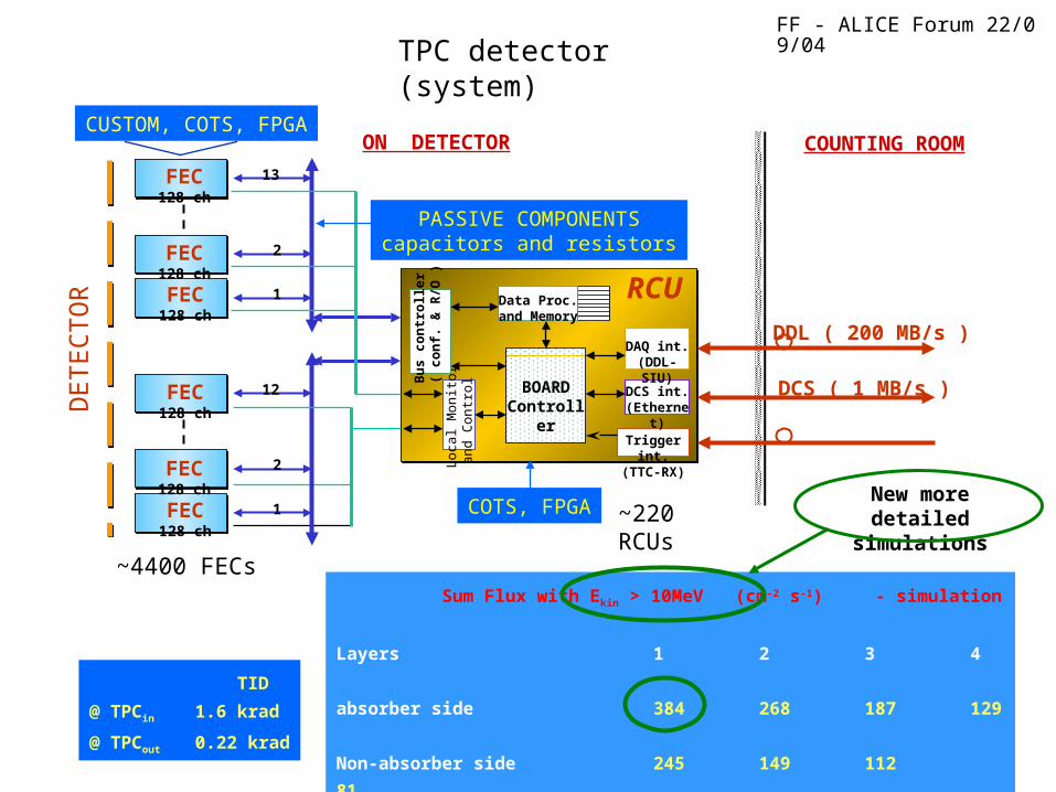
TPC detector (system)
Lo
cal M
onito
ra
nd
Co
ntr
ol BOARD
Controller
RCU
DCS ( 1 MB/s )
DDL ( 200 MB/s )
COUNTING ROOM
COTS, FPGA
ON DETECTOR
Bu
s c
on
tro
ller
( c
on
f. &
R/O
)
FEC128 ch
1
1
2
2
12
13
DCS int.(Ethernet)
DAQ int.(DDL-SIU)
Trigger int.(TTC-RX)
FEC128 ch
FEC128 ch
FEC128 ch
FEC128 ch
FEC128 ch
CUSTOM, COTS, FPGA
DE
TE
CT
OR
Data Proc.and Memory
PASSIVE COMPONENTScapacitors and resistors
~4400 FECs
~220 RCUs
Sum Flux with Ekin > 10MeV (cm-2 s-1) - simulation
Layers 1 2 3 4
absorber side 384 268 187 129
Non-absorber side 245 149 112 81
TID
@ TPCin 1.6 krad
@ TPCout 0.22 krad
New more detailed
simulations

FF - ALICE Forum 22/09/04
Test (I)
2002
65 MeV protons beam
Proton Flux: 1·108 , 5·108 p/cm2 sUCL, Louvain-la-Neuve, Belgium
Test (II)
2003 - 2004
Oslo Cyclotron
Test (III)
2004
TSL (Uppsala) 38 and 180 MeV proton beam
Proton flux ~ 107 – 108 protons/cm² s
25 and 28 MeV proton beam
Proton flux ~ 107 – 108 protons/cm² s
TPC detector (FEC tests)
analog current
standbydigital current
register errors
PM errors
DM
errors
SEU errors
and other
protocol errors
ADC spikesand SEU
error counter
s
test phase
power status
ALTRO Test Program
KEY LEARNING POINTS
Large test campaign (all components on FEC & RCU, also many COTS for comparisons)
Preparation of several test cards (1 full year of PCB making)
Preparation of acquisition s/w
TID x30 Alice dose (safe enough)
SEU acceptable for application, never latchup (FPGA reconfiguration, register reloading, Hamming protection)
Special thanks to our collaborators

FF - ALICE Forum 22/09/04
TPC detector (RCU tests)
For RCU: several FPGAs were tested (Altera and Xilinx) and compared with literature data.
Errors per run (4 hours) per TPC system
RCU 3.7
SIU 1.0
DCS 1.9
Error rate is so low that one can cope with it, if SEUs can be detected instantenously or FPGA can be reconfigured in real-time (Xilinx Virtex II Pro) Plan to migrate to Xilinx
Cross section [cm2]
RCU FPGA – APEX20K400
6.0 x 10⁻⁹ 1.1 x 10⁻⁹
SIU FPGA – APEX20K60
1.6 x 10⁻⁹
DCS FPGA – EPXA1
2 x 10⁻⁹
• SEFI test with Xilinx Virtex-II Pro
Reconfiguration started after 200 seconds: errors are corrected continuously (NOTE: test for protocol verification! Upsets >>Alice and slow reconfiguration)
• Fallback solution: FLASH based FPGA (Actel): ProASICPlus FLASH Family FPGAs
Preliminary irradidation results for Actel FPGA (device: APA075):
Failure (probably latch-up) after fluence of 3.7 1011 protons/cm2 dose of 100k Rad
Expected dose in 10 years of ALICE: ~ 570 Rad
DAQ presentation
Periodic reprogramming; data taking not affected
FF - ALICE Forum 22/09/04
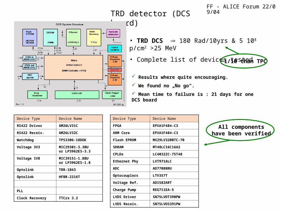
TRD detector (DCS board)
• TRD DCS 180 Rad/10yrs & 5 108 p/cm2 >25 MeV
• Complete list of devices tested
Device Type Device Name
FPGA EPXA1F484-C3
ARM Core EPXA1F484-C3
Flash EPROM MX29LV320BTC-70
SDRAM MT48LC16C16A2
CPLDs LC4032ZC-75T48
Ethernet Phy LXT971ALC
ADC AD7708BRU
Optocouplers LTV357T
Voltage Ref. AD1582ART
Charge Pump REG711EA-5
LVDS Driver SN75LVDT390PW
LVDS Receiv. SN75LVDS391PW
Device Type Device Name
RS422 Driver AM26LV31C
RS422 Receiv. AM26LV32C
Watchdog TPS3306-18DGK
Voltage 3V3 MIC29301-3.3BUor LP3962ES-3.3
Voltage 1V8 MIC39151-1.8BUor LP3962ES-1.8
Optolink TRR-1B43
Optolink HFBR-2316T
PLL
Clock Recovery TTCrx 3.2
Results where quite encouraging.
We found no „No go“.
Mean time to failure is : 21 days for one DCS board
All components have been verified
~1/10 than TPC

FF - ALICE Forum 22/09/04PHOS detector (system components)
FEE– APD + preamp (will go into beam August 31)– FEC (shaper + ALTRO)– TRU– TPC RCU
List of components that will be tested: 24LC256 MICROCHIP EEPROM
GTL16612_TSSOP Philips GTLAD7417_TSSOP ANALOG DEVICES Temperature Sensor
AD8039_SOIC ANALOG DEVICES OPAMPAD8544_SOIC ANALOG DEVICES OPAMP ALTRO-ST ST-Microelectronics ADC CY7C68013_ TQFP128 CYPRESS USBEP1K100-208_PQFP ALTERA FPGA EPC16 ALTERA FLASHKPC452 COSMO PHOTO COUPLER LM4041_1V2 NATIONAL REGULATOR LT1175_SOIC LINEAR REGULATORMAX4454_TSSOP MAXIM-IC OPAMPMAX5308_TSSOP MAXIM-IC OPAMPMAX6033-A,5.0V MAXIM-IC REGULATORMIC39151_TO263 MICREL REGULATORMIC5239_SOIC-5.0 MICREL REGULATORMIC5239_SOIC-ADJ MICREL REGULATORMPC940L TQFP32_080 MOTOROLA REGULATOROPA4364_TSSOP BURR-BROWN OPAMP40MHZ, CFPT_125 C_MAC OSCILATORTLC7733_SOIC Texas REGULATOR
Dose = 40 Rad
Shielding of 18 cm lead tungstate is not taken into account
Full wish list of components. Many already tested by TPC+TRD
Real case is safer

FF - ALICE Forum 22/09/04
HPTDC
HPTDC
Output Fifo
ReadoutController VME
Interface
EventManager
SRAM
SRAM
32
32
TRG
TRG
32
32
32
32
32
x 15
x 15
L2r
L2a
L1
INPUTS (LVDS)
INPUTS (LVDS)
~700 TRMs
Tested all TRM components during 2004 irradiations (up to 14krad)
SRAMHPTDC LUT
EVENT BUFFERS
FLASH
C
FIRMWARE FOR HPTDC LUT
Functionalities implemented by an FPGA
BOOTSEL WATCHDOG
VME BUS
~20000 TDCs
TOF detector (system on crates on-detector)
NINO is 0.25m tech: should be ok
(120rad/10yrs)
Other VME boards – DRM, LTM – use same components

FF - ALICE Forum 22/09/04
Device TOF (h-1)
STRATIX CONF
15.7
SRAM (HPTDC LUT 1.97 Mbit)
4.2
SRAM
(event buffers 4.0 Mbit)
4.3E-4
MTBF for Stratix too small despite of implementation of CRC check & reloading moving to Actel ProAsic Plus APA600 HPTDC LUT (for linearization) will be periodically monitored (CRC) + reload from Flash Error rates in event buffers depend on L1 rate, L2 latency + TOF occupancy. Error rates here are for L1=1 KHz , 30% TOF occupancy (exp. 15%)). CRC check will be implemented.
NOTE: • Atmel µC acts as controller of FPGA power fault (latchups) and CRC_ERROR pin• Monitor of errors in SRAM, FPGA internal memory + shift register logic check
HPTDCComponents
TOF (h-1)
CONF 2.3 10-2
READOUT FIFO(8Kb)
5.2 10-5
L1 BUFFER(8Kbx4)
1.6 10-4
MTBF (day)
1.8
800
260
TOF detector (TRM tests)
MTBF (min)
3.8
14.3
2300
Planned additional irradiation campaign for Slow Control device. Choices: PMC Power PC Arm processor Excalibur FPGA Optical links
FF - ALICE Forum 22/09/04
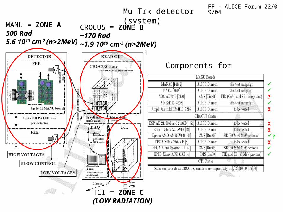
MANU = ZONE A500 Rad5.6 1010 cm-2 (n>2MeV)
CROCUS = ZONE B~170 Rad~1.9 1010 cm-2 (n>2MeV)
TCI = ZONE C(LOW RADIATION)
Components for irradiation
Mu Trk detector (system)
?
X X
X
X
?
FF - ALICE Forum 22/09/04
F.F. conclusions:
• Test campaign well started
• No problems in Mu Arm Trk Chambers for TID.
Only SEE to test.
• Main custom chips (MANAS, MARC) are ok
• Important verification to be done in zone A is the ADC
• Work to be concluded:
CROCUS crate electronics to test,
because devices that can affect large part of system.
• Warning: if PMD uses same electronics then TID becomes 26kRad (not 500)!
Mu Trk detector (first conclusions)
FF - ALICE Forum 22/09/04
FMD Module
ON DETECTOR INCOUNTING
ROOM
VA
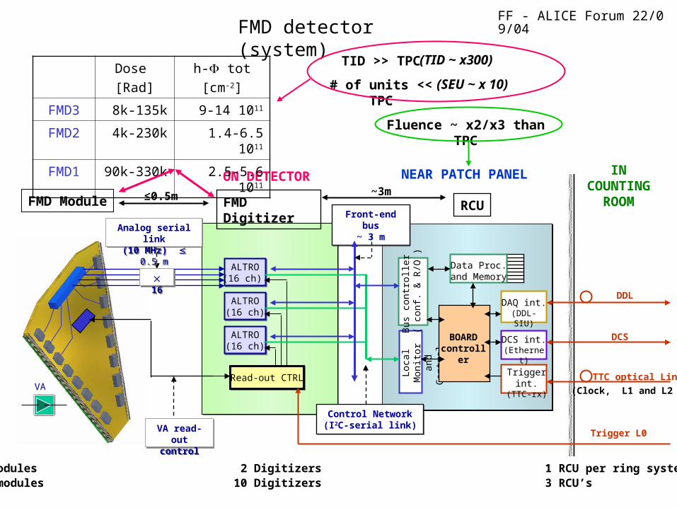
1 ring: 10/20 modules 2 Digitizers 1 RCU per ring systemFull FMD: 70 modules 10 Digitizers 3 RCU’s
VA read-outcontrol
VA read-outcontrol
TTC-RX
BOARDCTRL
FMD Digitizer
ALTRO(16 ch) ALTRO(16 ch)
ALTRO(16 ch)ALTRO(16 ch)
ALTRO(16 ch)ALTRO(16 ch)
Read-out CTRLRead-out CTRL
Loca
l Mon
itor
and
Con
trol
BOARDcontroller
Bus
con
trol
ler
( co
nf. &
R/O
)
DCS int.(Ethernet)
DAQ int.(DDL-SIU)
Trigger int.(TTC-rx)
Data Proc.and Memory
DCS
DDL
TTC optical Link
(Clock, L1 and L2 )
RCUFront-end bus
~ 3 mFront-end bus
~ 3 m
16 16
Control Network(I2C-serial link)
Control Network(I2C-serial link)
Trigger L0
NEAR PATCH PANEL
Analog serial link(10 MHz) 0.5 mAnalog serial link(10 MHz) 0.5 m
FMD detector (system)
Dose
[Rad]
h- tot
[cm-2]
FMD3 8k-135k 9-14 1011
FMD2 4k-230k 1.4-6.5 1011
FMD1 90k-330k 2.5-5.6 1011
≤0.5m ~3m
Fluence ~ x2/x3 than TPC
TID >> TPC
# of units << TPC
(TID ~ x300)
(SEU ~ x 10)

FF - ALICE Forum 22/09/04
Electronics components of FMD:
Preamp-shaper-multiplexer on hybrid: VA1_ALICE in 0.35 µm technology by IDEAS, Oslo Rad.level 20k-330k Rad
FMD Digitizer: use ALTROs and TPC FEC schematics + VA1 read-out protocol with common 10 MHz clock, to be built at NBI, Copenhagen Need to be aware of higher rad. levels than at TPC Rad.level 10k-100k Rad
RCU identical to the one from TPC and PHOS Rad.level 1k-10k Rad
FMD detector (results)
v.0.35m already tested up to few MRad
Validation to be done!
It should be OK

FF - ALICE Forum 22/09/04
• Crystal oscillators (Pletronics, Saronix, CFP, Ecliptek)
– TID 100 krad: negligible waveform change, no degradation
• Voltage regulators
– Micrel: increased noise (< 6 mV), noise peaks (20 mVpp), permanent damage (voltage shift) at 100 krad
– Linear Technology: increased noise (< 6 mV), no damage
• Electrical transceivers:
– Vitesse (GaAs): no damage up to 140 krad, 0 error @ 1012 n/cm2
– Texas Instruments (CMOS): no damage up to 400 krad
• Optical transceivers:
– Agilent: no damage up to 22.8 krad, 13 error @ 1012 n/cm2
– Infineon: no damage up to 28.5 krad, 6 error @ 1012 n/cm2
DAQ (DDL-SIU component tests)
Complete test of SIU

FF - ALICE Forum 22/09/04
Altera
APEX 20K60E
SERDES
Conf.
EPROM
OpticalTransceiver
Data path(2x16 bits)+ control
BER + CL
BER BER
Covered by CRC
Data path(serial)
BER bit error rateCL configuration loss
• Present DDL implemented with ALTERA APEX-E (currently EP20K60E 160k gates - 0.18 )
• Radiation tests have shown that we should expect 1 loss of configuration in 1 of the 400 DDL SIUs every hour
• With the present design, some of these loss will not be detected
Actel
APA 150 or 300
SERDES OpticalTransceiver
Data path
(serial)
Data path(2x16 bits)+ control
BER
BER BER
Covered by CRC
Power JTAG
optional
Possible re-design flash FPGA (ACTEL)
DAQ (DDL component tests)
Other “less prioritized” possibilities:
• Altera with CRC pin (status of configuration) Cyclone
• Xilinx with real time re-programmability option Virtex
• Make an ASIC
Good compromise
Safe by nature
A proto possibly by end of year
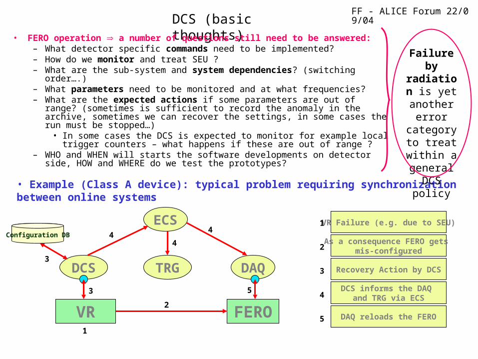
FF - ALICE Forum 22/09/04DCS (basic thoughts)
• FERO operation a number of questions still need to be answered:– What detector specific commands need to be implemented? – How do we monitor and treat SEU ?– What are the sub-system and system dependencies? (switching order….)– What parameters need to be monitored and at what frequencies? – What are the expected actions if some parameters are out of range?
(sometimes is sufficient to record the anomaly in the archive, sometimes we can recover the settings, in some cases the run must be stopped…)
• In some cases the DCS is expected to monitor for example local trigger counters – what happens if these are out of range ?
– WHO and WHEN will starts the software developments on detector side, HOW and WHERE do we test the prototypes?
• Example (Class A device): typical problem requiring synchronization between online systems
VR Failure (e.g. due to SEU)
Recovery Action by DCS
As a consequence FERO gets mis-configured
DCS informs the DAQ and TRG via ECS
DAQ reloads the FERO
DCS DAQTRG
FEROVR
ECSConfiguration DB
1
2
3
4
5
41
2
3
4
5
3
4
Failure by radiation
is yet another
error category to treat within a general
DCS policy
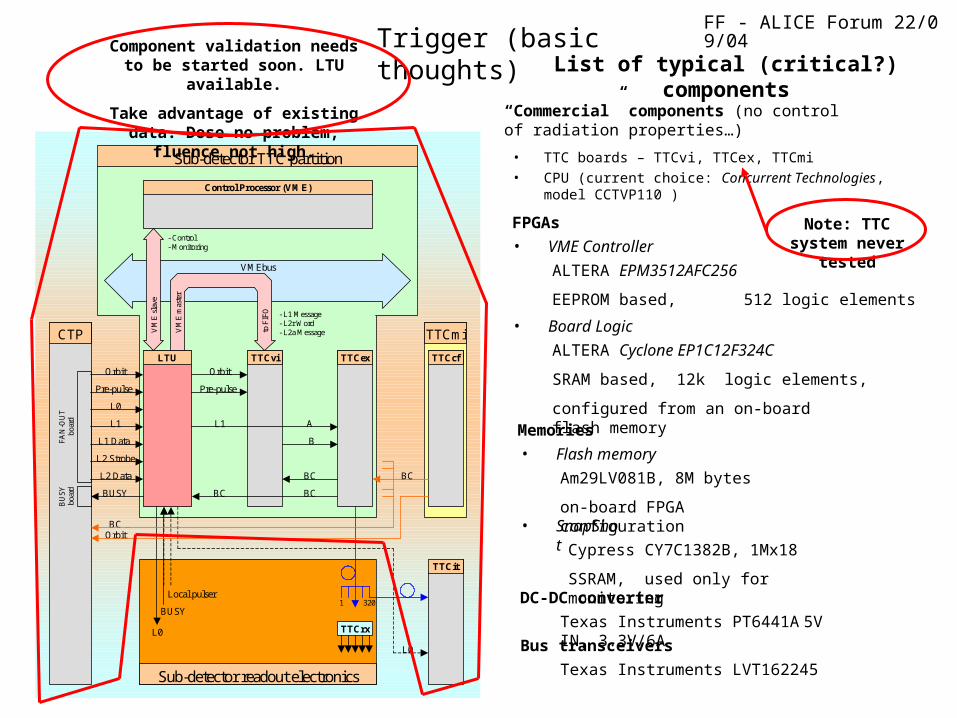
FF - ALICE Forum 22/09/04Trigger (basic thoughts)
L2 Data
L1
BC
L1 Data
L0
LTU Orbit
Pre-pulse
TTCvi Orbit
Pre-pulse
L1
BC BC
A
B
TTCex
TTCcf
BC BC
TTCit
320
1
TTCrx
L0
L0
BUSY
Local pulser
Sub-detector readout electronics
Sub-detector TTC partition
CTP TTCmi
Orbit
BUSY
L2 Strobe
Control Processor (VME)
- Control - Monitoring
VMEbus
BU
SY
bo
ard
VM
E s
lave
VM
E m
aste
r
FA
N-O
UT
bo
ard
to F
IFO
- L1 Message - L2r Word - L2a Message
List of typical (critical?) components
• TTC boards – TTCvi, TTCex, TTCmi • CPU (current choice: Concurrent Technologies, model
CCTVP110 )
“Commercial” components (no control of radiation properties…)
• VME Controller
FPGAs
ALTERA EPM3512AFC256
EEPROM based, 512 logic elements
• Board Logic
ALTERA Cyclone EP1C12F324C
SRAM based, 12k logic elements,
configured from an on-board flash memory
• Flash memory
Memories
Am29LV081B, 8M bytes
on-board FPGA configuration• SnapShot
Cypress CY7C1382B, 1Mx18
SSRAM, used only for monitoringDC-DC converter
Bus transceivers
Texas Instruments PT6441A 5V IN, 3.3V/6A
Texas Instruments LVT162245
Note: TTC system never tested
Component validation needs to be started soon. LTU available.
Take advantage of existing data. Dose no problem, fluence not high.

FF - ALICE Forum 22/09/04
Power Supply (CAEN EASY)
NOTE:
Tests made to fulfill CMS environment
(x100 more than ALICE)
Not guaranteed rad tolerant
Guaranteed rad tolerant
Results
Conditions
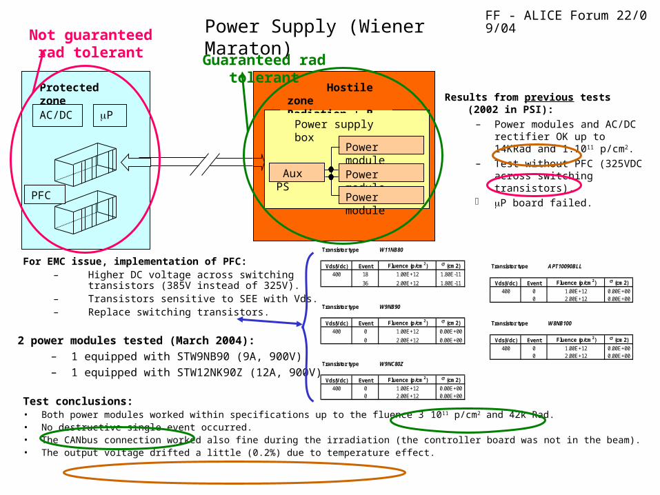
FF - ALICE Forum 22/09/04Power Supply (Wiener Maraton)
Power module
AC/DC
Hostile zoneRadiation + B field
Protected zone
Power supply box
Aux PS
Power module
Power module
PFC
P
Results from previous tests (2002 in PSI):
– Power modules and AC/DC rectifier OK up to 14KRad and 1.1011 p/cm2.
– Test without PFC (325VDC across switching transistors).
P board failed.
Transistor type W11NB80
Vds(Vdc) Event Fluence (p/cm2) (cm2) Transistor type APT10090BLL400 18 1.00E+12 1.80E-11
36 2.00E+12 1.80E-11 Vds(Vdc) Event Fluence (p/cm2) (cm2)
400 0 1.00E+12 0.00E+000 2.00E+12 0.00E+00
Transistor type W9NB90
Vds(Vdc) Event Fluence (p/cm2) (cm2) Transistor type W8NB100400 0 1.00E+12 0.00E+00
0 2.00E+12 0.00E+00 Vds(Vdc) Event Fluence (p/cm2) (cm2)
400 0 1.00E+12 0.00E+000 2.00E+12 0.00E+00
Transistor type W9NC80Z
Vds(Vdc) Event Fluence (p/cm2) (cm2)
400 0 1.00E+12 0.00E+000 2.00E+12 0.00E+00
2 power modules tested (March 2004):
– 1 equipped with STW9NB90 (9A, 900V)
– 1 equipped with STW12NK90Z (12A, 900V)
For EMC issue, implementation of PFC:– Higher DC voltage across switching transistors
(385V instead of 325V).– Transistors sensitive to SEE with Vds.– Replace switching transistors.
Test conclusions:• Both power modules worked within specifications up to the fluence 3 1011 p/cm2 and 42k Rad. • No destructive single event occurred. • The CANbus connection worked also fine during the irradiation (the controller board was not in the beam).• The output voltage drifted a little (0.2%) due to temperature effect.
Not guaranteed rad tolerant Guaranteed rad tolerant
FF - ALICE Forum 22/09/04
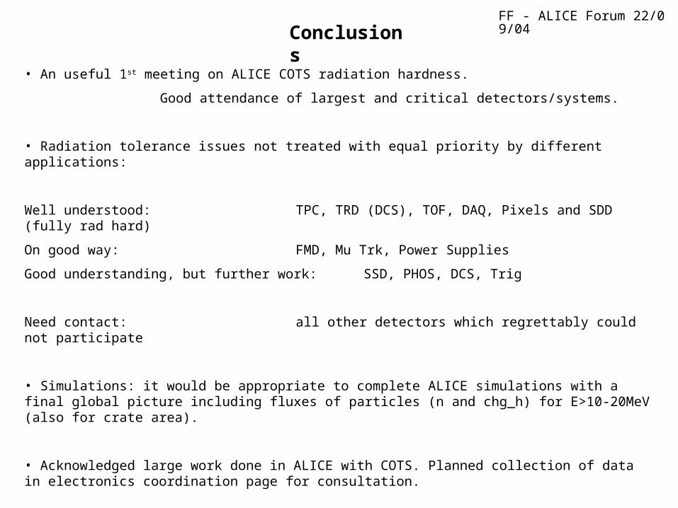
Conclusions
• An useful 1st meeting on ALICE COTS radiation hardness.
Good attendance of largest and critical detectors/systems.
• Radiation tolerance issues not treated with equal priority by different applications:
Well understood: TPC, TRD (DCS), TOF, DAQ, Pixels and SDD (fully rad hard)
On good way: FMD, Mu Trk, Power Supplies
Good understanding, but further work: SSD, PHOS, DCS, Trig
Need contact: all other detectors which regrettably could not participate
• Simulations: it would be appropriate to complete ALICE simulations with a final global picture including fluxes of particles (n and chg_h) for E>10-20MeV (also for crate area).
• Acknowledged large work done in ALICE with COTS. Planned collection of data in electronics coordination page for consultation.