Embed Size (px)
Citation preview
cod.
354
1F31
0 —
Rev
. 0 -
0/2
014
FERcondens 25 HE
���
��� ���
���
�� ���
I N S T R U C T I O N S F O R U S E , I N S T A L L A T I O N A N D M A I N T E N A N C E
FERcondens 25 HE
2 EN cod. 3541F310 - Rev. 01 - 06/2014
EN1. GENERAL WARNINGS• Carefully read and follow the instructions contained in this instruction booklet.• After boiler installation, inform the user regarding its operation and give him this manual, which is an integral
and essential part of the product and must be kept with care for future reference.• Installation and maintenance must be carried out by professionally qualified personnel, in compliance with
the current regulations and according to the manufacturer's instructions. Do not carry out any operation onthe sealed control parts.
• Incorrect installation or inadequate maintenance can result in damage or injury. The Manufacturer declinesany liability for damage due to errors in installation and use, or failure to follow the instructions.
• Before carrying out any cleaning or maintenance operation, disconnect the unit from the electrical power sup-ply using the switch and/or the special cut-off devices.
• In case of a fault and/or poor operation, deactivate the unit and do not try to repair it or directly intervene.Contact professionally qualified personnel. Any repair/replacement of the products must only be carried outby qualified personnel using original replacement parts. Failure to comply with the above could affect thesafety of the unit.
• This unit must only be used for its intended purpose. Any other use is deemed improper and therefore haz-ardous.
• The packing materials are potentially hazardous and must not be left within the reach of children.• The unit must not be used by people (including children) with limited physical, sensory or mental abilities or
without experience and knowledge of it, unless instructed or supervised in its use by someone responsiblefor their safety.
• The unit and its accessories must be appropriately disposed of, in compliance with the current regulations.• The images given in this manual are a simplified representation of the product. In this representation there
may be slight and insignificant differences with respect to the product supplied.
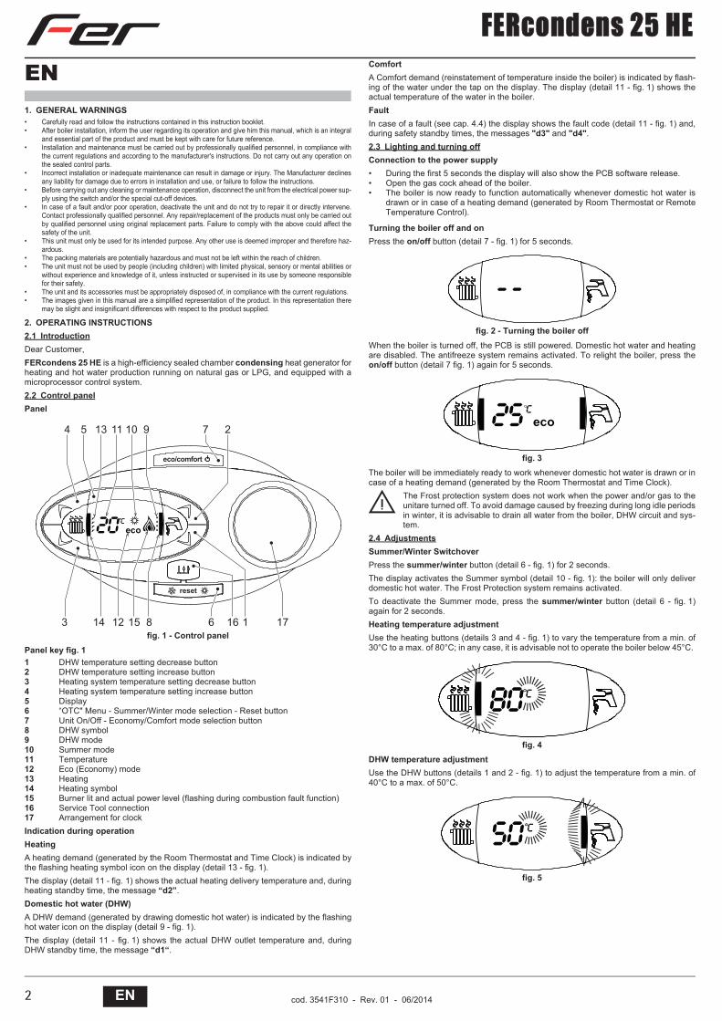
2. OPERATING INSTRUCTIONS2.1 IntroductionDear Customer,FERcondens 25 HE is a high-efficiency sealed chamber condensing heat generator forheating and hot water production running on natural gas or LPG, and equipped with amicroprocessor control system.2.2 Control panelPanel
fig. 1 - Control panelPanel key fig. 11 DHW temperature setting decrease button2 DHW temperature setting increase button3 Heating system temperature setting decrease button4 Heating system temperature setting increase button5 Display6 “OTC" Menu - Summer/Winter mode selection - Reset button7 Unit On/Off - Economy/Comfort mode selection button8 DHW symbol9 DHW mode10 Summer mode11 Temperature12 Eco (Economy) mode13 Heating14 Heating symbol15 Burner lit and actual power level (flashing during combustion fault function)16 Service Tool connection17 Arrangement for clockIndication during operationHeatingA heating demand (generated by the Room Thermostat and Time Clock) is indicated bythe flashing heating symbol icon on the display (detail 13 - fig. 1).The display (detail 11 - fig. 1) shows the actual heating delivery temperature and, duringheating standby time, the message “d2”.Domestic hot water (DHW)A DHW demand (generated by drawing domestic hot water) is indicated by the flashinghot water icon on the display (detail 9 - fig. 1).The display (detail 11 - fig. 1) shows the actual DHW outlet temperature and, duringDHW standby time, the message “d1“.
ComfortA Comfort demand (reinstatement of temperature inside the boiler) is indicated by flash-ing of the water under the tap on the display. The display (detail 11 - fig. 1) shows theactual temperature of the water in the boiler.FaultIn case of a fault (see cap. 4.4) the display shows the fault code (detail 11 - fig. 1) and,during safety standby times, the messages "d3" and "d4".2.3 Lighting and turning offConnection to the power supply• During the first 5 seconds the display will also show the PCB software release.• Open the gas cock ahead of the boiler.• The boiler is now ready to function automatically whenever domestic hot water is
drawn or in case of a heating demand (generated by Room Thermostat or RemoteTemperature Control).
Turning the boiler off and onPress the on/off button (detail 7 - fig. 1) for 5 seconds.
fig. 2 - Turning the boiler offWhen the boiler is turned off, the PCB is still powered. Domestic hot water and heatingare disabled. The antifreeze system remains activated. To relight the boiler, press theon/off button (detail 7 fig. 1) again for 5 seconds.
fig. 3The boiler will be immediately ready to work whenever domestic hot water is drawn or incase of a heating demand (generated by the Room Thermostat and Time Clock).
BThe Frost protection system does not work when the power and/or gas to theunitare turned off. To avoid damage caused by freezing during long idle periodsin winter, it is advisable to drain all water from the boiler, DHW circuit and sys-tem.
2.4 AdjustmentsSummer/Winter SwitchoverPress the summer/winter button (detail 6 - fig. 1) for 2 seconds.The display activates the Summer symbol (detail 10 - fig. 1): the boiler will only deliverdomestic hot water. The Frost Protection system remains activated.To deactivate the Summer mode, press the summer/winter button (detail 6 - fig. 1)again for 2 seconds.Heating temperature adjustmentUse the heating buttons (details 3 and 4 - fig. 1) to vary the temperature from a min. of30°C to a max. of 80°C; in any case, it is advisable not to operate the boiler below 45°C.
fig. 4DHW temperature adjustmentUse the DHW buttons (details 1 and 2 - fig. 1) to adjust the temperature from a min. of40°C to a max. of 50°C.
fig. 5
�����
���������
� �� �� �� � � �
����������
��
��������������������
��������������������

FERcondens 25 HE
3ENcod. 3541F310 - Rev. 01 - 06/2014
Room temperature adjustment (with optional room thermostat)Using the room thermostat, set the temperature required in the rooms. If the room ther-mostat is not installed, the boiler will keep the system at the set system delivery setpointtemperature.ECO/COMFORT selectionThe unit has a function that ensures a high domestic hot water delivery speed and max-imum comfort for the user. When the device is activated (COMFORT mode), the watercontained in the boiler is kept hot, thereby ensuring immediate availability of hot wateron opening the tap, without waiting times.The user can deactivate the device (ECO mode) by pressing the eco/comfort button(detail 7 - fig. 1). In ECO mode the display activates the ECO symbol (detail 12 - fig. 1).To activate the COMFORT mode, press the eco/comfort button (detail 7 - fig. 1) again.Outside Temperature Compensation (OTC)When the optional external probe is installed, the boiler adjustment system works in con-junction with the outside temperature. In this mode, the temperature of the heating sys-tem is controlled according to the outside weather conditions, to ensure high comfort andenergy saving throughout the year. In particular, the system delivery temperature is de-creased as the outside temperature increases, according to a specific "compensationcurve”.With OTC Temperature adjustment, the temperature set with the heating buttons (detail3 - fig. 1) becomes the maximum system delivery temperature. It is advisable to set amaximum value to allow system adjustment throughout its useful operating range.The boiler should be adjusted at the time of installation by qualified personnel. Possibleadjustments can in any case be made by the user to improve comfort.Compensation curve and curve offsetPress the reset button (detail 6 - fig. 1) for 5 seconds to access the OTC menu; the dis-play shows "CU" flashing.Use the DHW buttons (detail 1 - fig. 1) to adjust the curve from 1 to 10 according to thecharacteristic. By setting the curve to 0, OTC is disabled (Set to 8 or 9 for UK market).Press the heating buttons (detail 3 - fig. 1) to access parallel curve offset; the displayshows "OF" flashing. Use the DHW buttons (detail 1 - fig. 1) to adjust the parallel curveoffset according to the characteristic (fig. 6).Press the reset button (detail 6 - fig. 1) again for 5 seconds to exit the OTC menu.If the room temperature is lower than the required value, it is advisable to set a higherorder curve and vice versa. Proceed by increasing or decreasing in steps of one andcheck the result in the room.
fig. 6 - Example of compensation parallel curve offsetAdjustments from Remote Timer Control
AIf the Remote Timer Control (optional) is connected to the boiler, the above ad-justments are managed according to that given in table 1.
Table. 1
Water system pressure regulationThe filling pressure read on the boiler water gauge with the system cold must be approx1.0 - 1.5 bar. If the system pressure falls to values below minimum, the boiler stops andfault F37 is displayed.3. INSTALLATION3.1 General Instructions
BThis unit must only be used for its intended purpose. This unit is designed toheat water to a temperature below boiling point and must be connected to aheating system and/or a water supply system for domestic use, compatible withits performance, characteristics and its heating capacity. Any other use isdeemed improper.
BOILER INSTALLATION MUST ONLY BE CARRIED OUT BY QUALIFIED PERSON-NEL, IN ACCORDANCE WITH ALL THE INSTRUCTIONS GIVEN IN THIS TECHNICALMANUAL, THE PROVISIONS OF CURRENT LAW, THE PRESCRIPTIONS OF THETECHNICAL STANDARDS (BS), ANY LOCAL REGULATIONS AND THE RULES OFPROPER WORKMANSHIP.
Incorrect installation can cause damage or injury for which the manufacturer declinesany responsibility.Installation of this unit must be carried out in strict compliance with the presentinstructions and the following regulations applicable in Great Britain.Gas Safety Regulations (Installations & Use).Local Building Regulations..The Building Regulations (Part L).The Buildings Standards (Scotland - Consolidated) Regulations. British StandardsCodes of Practice (BSI):
Model Water By-Laws
For Northern Ireland, observe the current applicable regulations.Safe handling of materialsPay attention when handling the boiler insulation panels because the material they aremade of could irritate the skin. No part of the boiler contains asbestos, mercury or CFC's.Advice for transport and handlingFor lifting and transport always take suitable safety precautions: keep your back straight,bend knees, do not turn your body, move feet, avoid bending forward or sideways andkeep the load as close as possible to your body.If possible, use a trolley or other suitable means to carry the boiler.Grip the boiler firmly and, before lifting it, try and find the point where the load is concen-trated in order to establish the centre of gravity and suitably reposition yourself.3.2 Place of installationThe combustion circuit is sealed with respect to the place of installation, therefore theunit can be installed in any room. However, the place of installation must be sufficientlyventilated to prevent the creation of dangerous conditions in case of even small gasleaks. This safety standard is required by the EEC Directive no. 2009/142 for all gasunits, including those with sealed chamber.Therefore the place of installation must be free of dust, flammable materials or objectsor corrosive gases.The boiler is arranged for wall mounting and comes standard with a hooking bracket. Fixthe bracket to the wall according to the measurements given in the cover drawing and hookthe boiler on it. A metal template for marking the drilling points on the wall is available byrequest. The wall fixing must ensure stable and effective support for the generator.
AIf the unit is enclosed in a cabinet or mounted alongside, a space must be pro-vided for removing the casing and for normal maintenance operations.
Heating temperature setting Adjustment can be made from the Remote Timer Control menu and the boiler control panel.
Hot water temperature adjustment Adjustment can be made from the Remote Timer Control menu and the boiler control panel.
Summer/Winter Switchover Summer mode has priority over a possible Remote Timer Control heating demand.
Eco/Comfort selection Adjustment can only be made from the boiler control panel.
��
��
��
�
��
��
�
��
��
��
��
�
��
��
�
��
�
�
�
�
���� �
�
�
�
����� �
��� ������� ��� �������
B.S. 5440 -1 FluesB.S. 5440 -2 Air supply and ventilationB.S. 5449 ......... Systems for hot water production with forced circulationB.S. 6798 ......... Installation of gas-fired boilers for hot waterB.S. 6891 ......... Gas systemsB.S. 7671 ......... IEE wiring system regulationsB.S. 4814 ......... Specifications for expansion tanksB.S. 5482 ......... LPG systemsB.S. 7593 ......... Water treatment in central heating systems for domestic hot water productionB.S. 5546 ......... Installation of systems for domestic hot water production
B.S. 5955-8 ......... Installation of plastic pipes
�
� �
��
����
��������������������������������������������
�����
FERcondens 25 HE
4 EN cod. 3541F310 - Rev. 01 - 06/2014
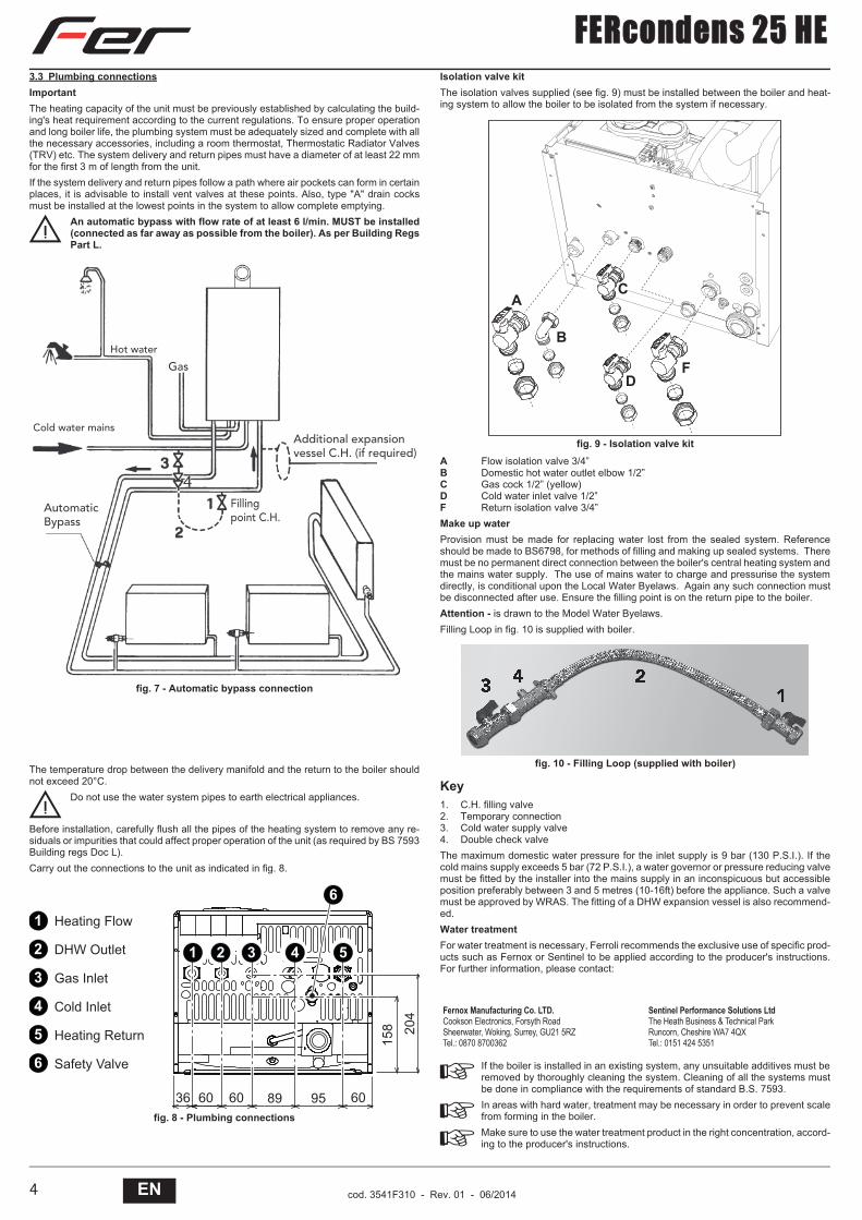
3.3 Plumbing connectionsImportantThe heating capacity of the unit must be previously established by calculating the build-ing's heat requirement according to the current regulations. To ensure proper operationand long boiler life, the plumbing system must be adequately sized and complete with allthe necessary accessories, including a room thermostat, Thermostatic Radiator Valves(TRV) etc. The system delivery and return pipes must have a diameter of at least 22 mmfor the first 3 m of length from the unit.If the system delivery and return pipes follow a path where air pockets can form in certainplaces, it is advisable to install vent valves at these points. Also, type "A" drain cocksmust be installed at the lowest points in the system to allow complete emptying.
BAn automatic bypass with flow rate of at least 6 l/min. MUST be installed(connected as far away as possible from the boiler). As per Building RegsPart L.
fig. 7 - Automatic bypass connection
The temperature drop between the delivery manifold and the return to the boiler shouldnot exceed 20°C.
BDo not use the water system pipes to earth electrical appliances.
Before installation, carefully flush all the pipes of the heating system to remove any re-siduals or impurities that could affect proper operation of the unit (as required by BS 7593Building regs Doc L).Carry out the connections to the unit as indicated in fig. 8.
fig. 8 - Plumbing connections
Isolation valve kitThe isolation valves supplied (see fig. 9) must be installed between the boiler and heat-ing system to allow the boiler to be isolated from the system if necessary.
fig. 9 - Isolation valve kitA Flow isolation valve 3/4”B Domestic hot water outlet elbow 1/2”C Gas cock 1/2” (yellow)D Cold water inlet valve 1/2”F Return isolation valve 3/4” Make up waterProvision must be made for replacing water lost from the sealed system. Referenceshould be made to BS6798, for methods of filling and making up sealed systems. Theremust be no permanent direct connection between the boiler's central heating system andthe mains water supply. The use of mains water to charge and pressurise the systemdirectly, is conditional upon the Local Water Byelaws. Again any such connection mustbe disconnected after use. Ensure the filling point is on the return pipe to the boiler.Attention - is drawn to the Model Water Byelaws.Filling Loop in fig. 10 is supplied with boiler.
fig. 10 - Filling Loop (supplied with boiler)
Key1. C.H. filling valve2. Temporary connection3. Cold water supply valve4. Double check valveThe maximum domestic water pressure for the inlet supply is 9 bar (130 P.S.I.). If thecold mains supply exceeds 5 bar (72 P.S.I.), a water governor or pressure reducing valvemust be fitted by the installer into the mains supply in an inconspicuous but accessibleposition preferably between 3 and 5 metres (10-16ft) before the appliance. Such a valvemust be approved by WRAS. The fitting of a DHW expansion vessel is also recommend-ed.Water treatmentFor water treatment is necessary, Ferroli recommends the exclusive use of specific prod-ucts such as Fernox or Sentinel to be applied according to the producer's instructions.For further information, please contact:
AIf the boiler is installed in an existing system, any unsuitable additives must beremoved by thoroughly cleaning the system. Cleaning of all the systems mustbe done in compliance with the requirements of standard B.S. 7593.
AIn areas with hard water, treatment may be necessary in order to prevent scalefrom forming in the boiler.
AMake sure to use the water treatment product in the right concentration, accord-ing to the producer's instructions.
Gas
Hot water
Additional expansion vessel C.H. (if required)
Fillingpoint C.H.
AutomaticBypass
Cold water mains
�� �� �� � � ��
���
�
�
�
�
�
�
�������� ��!
"�#�$%����
&�'������
(��)������
��������*��%+�
,�-��.�/����
� �
�� �
Fernox Manufacturing Co. LTD.Cookson Electronics, Forsyth RoadSheerwater, Woking, Surrey, GU21 5RZTel.: 0870 8700362
Sentinel Performance Solutions LtdThe Heath Business & Technical ParkRuncorn, Cheshire WA7 4QXTel.: 0151 424 5351
�
�
��
�

FERcondens 25 HE
5ENcod. 3541F310 - Rev. 01 - 06/2014
3.4 Gas connectionThe gas must be connected to the relevant union in conformity with the current regulations, with a rigidmetal pipe or with a continuous surface flexible s/steel tube, installing a gas cock between the systemand boiler. Make sure all the gas connections are tight.3.5 Electrical connectionsImportant
BThe unit must be connected to an efficient earthing system in conformity with current safetyregulations. Have the efficiency and suitability of the earthing system checked by profession-ally qualified personnel; the Manufacturer declines any liability for damage caused by failureto earth the system.The boiler is prewired and provided with a "Y" type cable (without plug) for connection to theelectric line. The connections to the power supply must be permanent and equipped with adouble-pole switch with contact opening distance of at least 3 mm, installing fuses of max. 3Abetween the boiler and the line. Make sure to respect the polarities (LINE: brown wire / NEU-TRAL: blue wire / EARTH: yellow/green wire) in connections to the electric line.
BThe unit's power cable must not be replaced by the user; if damaged, switch the unit off andhave the cable replaced by professionally qualified personnel. If replacing the power cable,only use "HAR H05 VV-F" 3x0.75 mm2 cable with max. ext. diameter of 8 mm.
Room thermostat
BIMPORTANT: THE ROOM THERMOSTAT MUST HAVE VOLTAGE-FREECONTACTS. CONNECTING 230 V TO THE ROOM THERMOSTAT TERMI-NALS WILL PERMANENTLY DAMAGE THE ELECTRONIC BOARD.When connecting time controls or a timer, do not take the power supply for these devices fromtheir breaking contacts Their power supply must be by means of direct connection from themains or with batteries, depending on the kind of device.
Accessing the electrical terminal blockFollow the instructions given in fig. 11 to access the electrical connections terminal block. The layout ofthe terminals for the various connections is also given in the wiring diagram in fig. 27.
fig. 11 - Accessing the terminal block3.6 FLue PipesImportantThe unit is “type C” with sealed chamber and forced draught; the air inlet and flue outlet must be con-nected to one of the following extraction/suction systems. Before installation, check and carefully ob-serve the above prescriptions. Also, comply with the provisions concerning the positioning of wall and/or roof terminals and the minimum distances from windows, walls, vents, etc.Expansion
AFor flue exhaust pipes longer than 1 metre, during installation take in account the natural ex-pansion of the materials when the boiler is operating.To prevent any deformation, leave an expansion space of approx. 2 ÷ 4 mm for every metreof pipe.
Flue RestrictorsBoiler operation requires fitting the flue restrictors supplied with the unit, according to that given in thefollowing tables.Before inserting the flue exhaust pipe, check the presence of the correct flue restrictor (when it is to beused) and that it is correctly positioned. The boilers are fitted as standard with the smallest diameter fluerestrictor. To replace the flue restrictor (ref. 1 - fig. 12), proceed as indicated in fig. 12 and Table 3 orTable 5.
fig. 12
Connection with coaxial pipesStandard coaxial installation
fig. 13 - Standard coaxial installationOther coaxial connections
fig. 14 - Examples of connection with coaxial pipes ( = Air / = Fumes)
Table. 2 - Typology
For coaxial connection, fit the unit with one of the following starting accessories. For thewall hole dimensions, see fig. 13. Standard coaxial flues must be fitted level. Any horizontal sections of the flue exhaust in excess of 1 m must be kept slopingtowards the boiler at an angle of 3°, to allow for adequate draining of condensatefrom the flue.
fig. 15 - Starting accessory for coaxial ducts
��!
"�
�
��#
� �
� � �
�
Type DescriptionC1X Wall horizontal exhaust and inletC3X Roof vertical exhaust and inlet
��
��� ���
�
���
���
0�����
���
�
���
���
0���
�������������� �� ������������������������
���������������
�����������������
���� ��� ���
���� ��� ���
�� ���
��$ ��$��$ ��$ ��$��$
������1�
������1� ������1�
0����
0����
0����
0���
���
���
���
��
0�����
0�����

FERcondens 25 HE
6 EN cod. 3541F310 - Rev. 01 - 06/2014
Table. 3 - Baffles for coaxial ducts
Connection with separate pipes
fig. 16 - Examples of connection with separate pipes ( = Air / = Fumes)
Table. 4 - Typology
For connection of the separate ducts, fit the unit with the following starting accessory:
fig. 17 - Starting accessory for separate ductsBefore installation, check the flue restrictor to be used and make sure the maximum per-missible length has not been exceeded, by means of a simple calculation:1. Completely establish the layout of the system of split flues, including accessories
and outlet terminals.2. Consult the table 6 and identify the losses in meq (equivalent metres) of every com-
ponent, according to the installation position.3. Check that the sum total of losses is less than or equal to the maximum permissible
length in table 5.
Table. 5 - Baffles for separate ducts
Table. 6 - Accessories
Position of terminals
fig. 18
Coaxial 60/100 Coaxial 80/125Max. permissible length 6 m 12 mReduction factor 90° bend 1 m 0.5 mReduction factor 45° bend 0.5 m 0.25 m
Flue restrictor to use0 ÷ 2 m Ø 45 0 ÷ 6 m Ø 452 ÷ 4 m Ø 50 6 ÷ 12 m no restrictor4 ÷ 6 m no restrictor
Type DescriptionC1X Wall horizontal exhaust and intake. The inlet/outlet terminals must be concentric or close enough to be
undergo similar wind conditions (within 50 cm)C3X Roof vertical exhaust and intake. Inlet/outlet terminals like for C12C5X Wall or roof exhaust and intake separate or in any case in areas with different pressures. The exhaust and
intake must not be positioned on opposite walls.C6X Intake and exhaust with separately certified pipes (EN 1856/1)B2X Intake from installation room and wall or roof exhaust
IMPORTANT - THE ROOM MUST BE PROVIDED WITH APPROPRIATE VENTILATION
Separate ductsMax. permissible length 55 meq
Flue restrictor to use
0 ÷ 15 meq Ø 45
15 ÷ 35 meq Ø 50
35 ÷ 55 meq No restrictor
��% ��% ��% ��% &%
�����
0��0��
0��
0�� 0��
������1�
Losses in meq
Airinlet
Flue exhaustVertical Horizontal
Ø 80
PIPE 1 m M/F 1KWMA83W 1.0 1.6 2.0BEND 45° M/F 1KWMA65W 1.2 1.8
90° M/F 1KWMA01W 1,5 2.0PIPE SECTION with test point 1KWMA70W 0.3 0.3
TERMINAL air, wall 1KWMA85A 2.0 -flue, wall with antiwind 1KWMA86A - 5.0
FLUE split air/fumes 80/80 010027X0 - 12.0flue outlet only Ø80 010026X0 +
1KWMA86U- 4.0
Minimum dimensions of flue terminalsA Directly under an opening, air inlet, openable window, etc. 300 mmB Above an opening, air inlet, openable window, etc. 300 mmC Horizontally to an opening, air inlet, openable window, etc. 300 mmD Under gutters, drain pipes 75 mmE Under cornices or under eaves 200 mmF Under balconies or garages 200 mmG From a drain pipe or a vertical drain pipe 150 mmH From an internal or external corner 100 mmI Above ground level, a roof or balcony 300 mmJ From a surface facing the terminal 600 mmK From a terminal facing the terminal 1200 mmL From a garage opening (e.g. door, window) with access to the home 1200 mmM Vertically from a terminal on the same wall 1500 mmN Horizontally from a terminal on the same wall 300 mmO From the wall on which the terminal is fitted N/AP From a vertical structure on the roof 150 mmQ Above the intersection with the roof 300 mm
NOTES
• N/A = Not applicable• Also, the terminal must be at least 150 mm (in case of forced intake) from an opening made in the
structure of the building to house a fitted element such as a window frame.• Positions of condensing flue terminals: if the flue exhaust is provided for at a low level, the potential
effect of the flue gas cloud must be considered. Flue gas management kits are available by request.• The flue gas cloud must not be directed towards:
- A frequented approach- A window or door- An adjacent property
2
"3�4
5
5
�
6 (
7&
89
�
�:
;
;
<<
5

FERcondens 25 HE
7ENcod. 3541F310 - Rev. 01 - 06/2014
Connection to multiple or single flues with natural draught. (U-Ducts & SE-Ducts)To connect the FERcondens 25 HE boiler to a multiple flue or a single flue with naturaldraught, the flue or chimney must be expressly designed by professionally qualified tech-nical personnel in conformity with the current standards and regulations.In particular, flues and chimneys must:• Be sized according to the method of calculation given in the standard.• Be tight with respect to the products of combustion, resistant to the fumes and heat
and impermeable to condensate.• Have a circular or square cross-section (some hydraulically equivalent sections are
permissible), with a vertical progression and with no constrictions.• Have the ducts conveying the hot fumes at a suitable distance or separately from
combustible materials.• Be connected to just one unit per floor, for not more than 6 units (8 if there is a com-
pensation duct or opening).• Have no mechanical suction devices in the main ducts.• Be at low pressure, all along their length, in conditions of stationary operation.• Have at their base a collection chamber for solid materials or condensate, of at least
0.5 m, equipped with an airtight metal door.
3.7 Condensate drain connectionThe boiler has an internal trap for draining the condensate. Fit the inspection union A andthe flexible tube B, pressing it in for about 3 cm. Fill the trap with approx. 0.5 L of waterand connect the flexible tube to the drainage system.
fig. 19 - Condensate drain connection4. SERVICE AND MAINTENANCE4.1 AdjustmentsGas conversionThe unit can work on natural gas or LPG and is factory-set for use with one of these twogases, as clearly shown on the packing and data plate. Whenever a different gas to thatfor which the unit is arranged has to be used, the special conversion kit will be required,proceeding as follows:1. Disconnect the power supply ahead of the boiler and close the gas cock;2. Replace the injectors at the main burner and pilot burner, fitting the injectors indicat-
ed in the technical data table cap. 5.3, depending on the type of gas used3. Connect the power supply ahead of the boiler and open the gas cock;4. Modify the parameter for the type of gas:
• put the boiler in standby mode• press the DHW buttons details 1 and 2 - fig. 1 for 10 seconds: the display shows
“b01“ flashing.• press the DHW buttons details 1 and 2 - fig. 1) to set parameter 00 (for opera-
tion with natural gas) or 01 (for operation with LPG).• press the DHW buttons details 1 and 2 - fig. 1 for 10 seconds.• the boiler will return to standby mode
5. Adjust the minimum and maximum pressures at the burner (ref. relevant para-graph), setting the values given in the technical data table for the type of gas used
6. Apply the sticker, contained in the conversion kit, near the data plate as proof of theconversion.
TEST mode activationPress the heating buttons (details 3 and 4 - fig. 1) together for 5 seconds to activate the TEST mode.The boiler lights at the maximum heating power set as described in the following section.The heating and DHW symbols (fig. 20) flash on the display; the heating power will be displayed along-side.
fig. 20 - TEST mode (heating power = 100%)Press the heating buttons (details 3 and 4 - fig. 1) to increase or decrease the power (min.=0%,max.=100%).Press the DHW button "-" (detail 1 - fig. 1) and boiler power is immediately adjusted to min. (0%). Pressthe DHW button "+" (detail 2 - fig. 1) and boiler power is immediately adjusted to max. (100%).To deactivate the TEST mode, press the heating buttons (details 3 and 4 - fig. 1) for 5 seconds.The TEST mode is automatically disabled in any case after 15 minutes.
Pressure adjustment at the burnerSince this unit has flame modulation, there are two fixed pressure settings: minimum and maximum,which must be those given in the technical data table according to the type of gas.
Connect a suitable pressure gauge to pressure test point "B" downstream of the gas valve.Activate TEST mode.Press the Eco/Comfort button for 2 secs to access the gas valve calibration mode.Maximum burner pressure "q02" is then displayed. To view the value press DHW + button.Read the pressure gauge. If adjustment is required use the DHW +/- buttons to adjust until the pressuregauge reading is correct. (Wait 10 secs after each adjustment for pressure to stabilize).Press the CH "-" button. The display shows minimum burner pressure "q01"Use the DHW +/- buttons to adjust. Wait 10 secs for pressure to stabilize.Recheck both settings by pressing the CH +/- buttons. Adjust as necessary using above method.Press Eco/Comfort for 2 secs to return to TEST mode.Deactivate TEST mode.
Heating power adjustmentTo adjust the heating power, switch the boiler to TEST mode (see sec. 4.1). Press theheating buttons detail 3 - fig. 1 to increase or decrease the power (min. = 00 - max. =100). Press the reset button within 5 seconds and the max. power will remain at that set-ting. Exit TEST mode (see sec. 4.1).
��
fig. 21 - Gas valve
A - Upstream pressure pointB - Downstream pressure pointI - Gas valve electrical connectionR - Gas outletS - Gas inlet
fig. 22 - Gas valve connectionTYPE SGV100Pi max 65 mbar24 Vdc - class B+A
� � � ���������������
����������
���
� � ���
'
�
(
�
=���=����
����������

FERcondens 25 HE
8 EN cod. 3541F310 - Rev. 01 - 06/2014
4.2 StartupBefore lighting the boiler• Check the seal of the gas system.• Check correct prefilling of the expansion tank.• Fill the water system and make sure all air contained in the boiler and the system
has been vented.• Make sure there are no water leaks in the system, DHW circuits, connections or boiler.• Check correct connection of the electrical system and efficiency of the earthing system.• Make sure the gas pressure for heating is that required.• Make sure there are no flammable liquids or materials in the immediate vicinity of
the boiler
Checks during operation• Switch the unit on.• Check the tightness of the gas and water systems.• Check the efficiency of the flue and air ducts while the boiler is working.• Make sure the water is circulating properly between the boiler and the systems.• Make sure the gas valve modulates correctly in the heating and domestic hot water
production stages.• Check correct boiler lighting by performing various tests, turning it on and off with
the room thermostat or remote control.• Make sure the fuel consumption indicated on the meter matches that given in the
technical data table in cap. 5.• Make sure that with no demand for heating, the burner lights correctly on opening a
hot water tap. Check that in heating mode, on opening a hot water tap, the heatingcirculating pump stops and there is regular production of hot water.
• Make sure the parameters are programmed correctly and carry out any requiredcustomisation (compensation curve, power, temperatures, etc.).
4.3 MaintenancePeriodical checkTo ensure correct operation of the unit over time, have qualified personnel carry out ayearly check, providing for the following:• The control and safety devices (gas valve, flow switch, thermostats, etc.) must func-
tion correctly.• The flue exhaust circuit must be perfectly efficient.
(Sealed chamber boiler: fan, pressure switch, etc. -The sealed chamber must betight: seals, cable glands, etc.)(Open chamber boiler: anti-backflow device, flue thermostat, etc.)
• The flue pipes and terminals must be free of obstructions and leaks• The burner and exchanger must be clean and free of deposits. For possible cleaning
do not use chemical products or wire brushes.• The electrode must be properly positioned and free of scale.
fig. 23 - Electrode positioning• The gas and water systems must be airtight.• The water pressure in the cold water system must be about 1 bar; otherwise, bring
it to that value.• The circulating pump must not be blocked.• The expansion tank must be charged to 1 bar.• The gas flow and pressure must correspond to that given in the respective tables.
4.4 TroubleshootingDiagnosticsThe boiler is equipped with an advanced self-diagnosis system. In case of a boiler fault,the display will flash together with the fault symbol (detail 11 - fig. 1) indicating the faultcode.There are faults that cause permanent shutdown (marked with the letter "A"): to restoreoperation, press the RESET button (detail 6 - fig. 1) for 1 second or RESET on the op-tional remote timer control if installed; if the boiler fails to start, it is necessary to eliminatethe fault.Faults marked with the letter "F" cause temporary shutdowns that are automatically resetas soon as the value returns within the boiler's normal working range.
List of faults
Table. 7
��>��)�� �
Faultcode Fault Possible cause Cure
A01 No burner ignition
Excessive condensate level Empty / clean the trap
No gasCheck the regular gas flow to the boiler and that the air has been elimi-nated from the pipes
Ignition/detection electrode faultCheck the wiring of the electrode and that it is correctly positioned and free of any deposits
Faulty gas valve Check the gas valve and replace it if necessary
Gas valve wiring disconnected Check the wiringIgnition power too low Adjust the ignition power
A02 Flame present signal with burner off
Electrode fault Check the ionisation electrode wiringPCB fault Check the PCB
A03 Overtemperature protection activation
Heating sensor damaged Check the correct positioning and operation of the heating sensor
No water circulation in the system Check the circulating pumpAir in the system Vent the system
F04 Flue thermostat fault
Exchangers dirty (clogged on water side) Clean the exchangersFaulty water circulationFlue thermostat contact open Check the thermostatWiring disconnected Check the wiring
F05
Air pressure switch fault (contact fails to close) Wrong PCB parameter setting Check the PCB parameter and modify
it if necessary
Fan faultWiring disconnected Check the wiringFaulty fan Check the fanPCB fault Check the PCB
A06 No flame after the ignition phase
Low pressure in the gas system Check the gas pressureBurner minimum pressure setting Check the pressures
F07 PCB parameter fault Wrong PCB parameter setting Check the PCB parameter and modify it if necessary
A09 Gas valve faultWiring disconnected Check the wiring
Faulty gas valve Check the gas valve and replace it if necessary
F10 Delivery sensor 1 faultSensor damaged
Check the wiring or replace the sensorWiring shortedWiring disconnected
F11 DHW sensor faultSensor damaged
Check the wiring or replace the sensorWiring shortedWiring disconnected
F14 Delivery sensor 2 faultSensor damaged
Check the wiring or replace the sensorWiring shortedWiring disconnected
A16 Gas valve faultWiring disconnected Check the wiring
Faulty gas valve Check the gas valve and replace it if necessary
F20 Combustion control fault
Fan fault Check the fan and fan wiring
Wrong flue restrictor Check the flue restrictor and replace it if necessary
Flue not correctly sized or obstructed Check the flue
A21 Poor combustion fault Fault F20 generated 6 times in the last 10 minutes See fault F20
A23Set nominal system water pressure not reached within 4 minutes
Wrong PCB parameter setting Check the PCB parameter and modify it if necessary
A24 4 fillings within 24 hours Wrong PCB parameter setting Check the PCB parameter and modify it if necessary
F34 Supply voltage under 180V. Electric mains trouble Check the electrical systemF35 Faulty mains frequency Electric mains trouble Check the electrical system
F37 Incorrect system water pres-sure
Pressure too low Fill the systemWater pressure switch damaged or not connected Check the sensor
F39 External probe faultProbe damaged or wiring shorted Check the wiring or replace the sensorProbe disconnected after activat-ing the OTC
Reconnect the external probe or disa-ble the OTC
A41 Sensor positioning Delivery sensor or DHW sensor detached from the pipe
Check the correct positioning and operation of the sensors
F42 Heating sensor fault Sensor damaged Replace the sensor
F43 Exchanger protection acti-vation.
No system H2O circulation Check the circulating pumpAir in the system Vent the system
F50 Gas valve fault
Modulating Operator wiring dis-connected Check the wiring
Faulty gas valve Check the gas valve and replace it if necessary
A51 Poor combustion fault Inlet/exhaust flue obstruction Check the flue
FERcondens 25 HE
9ENcod. 3541F310 - Rev. 01 - 06/2014
5. TECHNICAL DATA AND CHARACTERISTICS
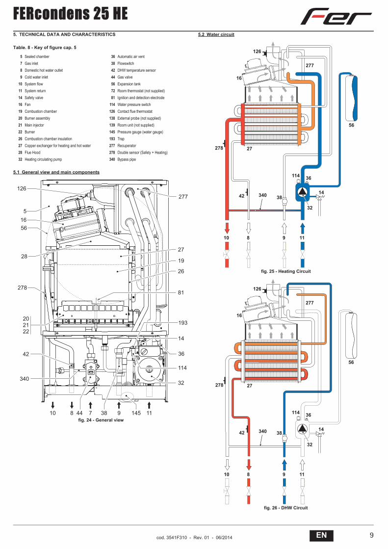
Table. 8 - Key of figure cap. 5
5.1 General view and main components
fig. 24 - General view
5.2 Water circuit
fig. 25 - Heating Circuit
fig. 26 - DHW Circuit
5 Sealed chamber 36 Automatic air vent7 Gas inlet 38 Flowswitch8 Domestic hot water outlet 42 DHW temperature sensor9 Cold water inlet 44 Gas valve
10 System flow 56 Expansion tank11 System return 72 Room thermostat (not supplied)14 Safety valve 81 Ignition and detection electrode16 Fan 114 Water pressure switch19 Combustion chamber 126 Contact flue thermostat20 Burner assembly 138 External probe (not supplied)21 Main injector 139 Room unit (not supplied)22 Burner 145 Pressure gauge (water gauge)26 Combustion chamber insulation 193 Trap27 Copper exchanger for heating and hot water 277 Recuperator28 Flue Hood 278 Double sensor (Safety + Heating)32 Heating circulating pump 340 Bypass pipe
�����
��
��
��
�
���
��
�� � ��
����
��
�� �
������
��
���
��
���
�
��
�
��
��!�� #
���
�"#
�#��
�
�""
��
�"
��
��� �
��
�
��!�� #
���
�"#
�#��
�
�""
��
�"
��
��� �
��
�

FERcondens 25 HE
10 EN cod. 3541F310 - Rev. 01 - 06/2014
5.3 Technical data table 5.4 DiagramsPressure - power diagrams FERcondens 25 HE
A = LPG - B = NATURAL GASCirculating pump head / pressure lossesFERcondens 25 HE
A = Boiler pressure losses - 1, 2 and 3 = Circulating pump speed
Data Unit FERcondens 25 HEMax. heating capacity kW 25.0 (Q)Min. heating capacity kW 10.0 (Q)Max. Heat Output in heating (80/60°C) kW 24.4 (P)Min. Heat Output in heating (80/60°C) kW 9.5 (P)Max. Heat Output in heating (50/30°C) kW 26.0Min. Heat Output in heating (50/30°C) kW 10.5Max. Heat Output in hot water production kW 24.4Min. Heat Output in hot water production kW 9.2
Efficiency class Directive 92/42 EEC -
NOx emission class - 3 (NOx)Burner injector G20 no.x Ø 11 x 1.35Gas supply pressure G20 mbar 20.0Max. gas pressure at burner (G20) mbar 11.0Min. gas pressure at burner (G20) mbar 2
Max. gas delivery G20 m3/h 2.64
Min. gas delivery G20 m3/h 1.06
Burner injector G31 no.x Ø 11 x 0.79Gas supply pressure G31 mbar 37Max. gas pressure at burner (G31) mbar 35.0Min. gas pressure at burner (G31) mbar 5.0Max. gas delivery G31 kg/h 1.96Min. gas delivery G31 kg/h 0.78Max. working pressure in heating bar 3 (PMS)Min. working pressure in heating bar 0.8Max. heating temperature °C 90 (tmax)Heating water content litres 1.5Heating expansion tank capacity litres 8Heating expansion tank prefilling pressure bar 1Max. working pressure in hot water production bar 9 (PMW)Min. working pressure in hot water production bar 0.25DHW flowrate t 25°C l/min 14DHW flowrate t 30°C l/min 11.6 (D)DHW flowrate t 35°C l/min 10Protection rating IP X5DPower supply voltage V/Hz 230V/50HzElectrical power input W 135Electrical power input in hot water production W 135Empty weight kg 35
Type of unitC12-C22-C32-C42-C52-C62-C72-C82
B22-B32
PIN CE 0461BU0942G.C. 47-267-61 NGG.C. 47-267-62 LPG
�
� � �� �� �� �� �� � � �� �� �� �� �� �� �� �� � �
�
��
�
��
�
��
�
�!��
�
�
�
�
�
�
�
�
� ��� ���� ���� ����
����� ��
����
����
�
�
�
�
�

FERcondens 25 HE
11ENcod. 3541F310 - Rev. 01 - 06/2014
5.5 Wiring diagram
fig. 27 - Electrical circuit
��?�
�
��������
�
;8
��
8;
@A @A
���
@A
��
����
��
�����
�����
���
��
�*��+����� ��
*4<$/4�A$�($;;4(AA�4
(8$(:
���
��� ��

© Heating and Hotwater Industry Council (HHIC)
www.centralheating.co.uk
Benchmark Commissioning and Servicing Section

This Commissioning Checklist is to be completed in full by the competent person who commissioned the boiler as a means of demonstrating compliance with the appropriate Building Regulations and then handed to the customer to keep for future reference.
GAS BOILER SYSTEM COMMISSIONING CHECKLIST
CONTROLS
Optimum start control
Fitted
Fitted
Fitted
Fitted
ALL SYSTEMS
Yes
Yes
CENTRAL HEATING MODE
OR
mbar OR mbar
Yes
Yes
DOMESTIC HOT WATER MODE
OR
mbar OR mbar
Yes Temperature
CONDENSING BOILERS ONLY
Yes
ALL INSTALLATIONS
AND ² Ratio
AND ² Ratio
Yes
Yes
Yes
Yes

It is that your heating system is serviced and that the appropriate Service Interval Record is completed.
Service Provider
SERVICE RECORD
SERVICE 01
AND ² %AND ² %
SERVICE 02
AND ² %AND ² %
SERVICE 03
AND ² %AND ² %
SERVICE 04
AND ² %AND ² %
SERVICE 05
AND ² %AND ² %
SERVICE 06
AND ² %AND ² %
SERVICE 07
AND ² %AND ² %
SERVICE 08
AND ² %AND ² %
SERVICE 09
AND ² %AND ² %
SERVICE 10
AND ² %AND ² %


Before contacting Fer please have available thecompleted BENCHMARK document (located in the back of this manual),
boiler serial number and model detail.
For Technical assistance during the installation, call ourTechnical Helpline on 0843 479 0479.
You will be required to provide your Gas Safe Register Number.
Should you require a Service Engineer to visit, call ourService Centre on 0843 479 0479.
Calls to these numbers are charged at National Rate from BT landlines.Calls made from mobile networks may be considerable more.
Phone numbers:
Installer
Service Engineer
BECAUSE OF OUR CONSTANT ENDEAVOUR FOR IMPROVEMENT DETAILS MAY VARY SLIGHTLY FROM THOSE QUOTED IN THESE INSTRUCTIONS.
ALL SPECIFICATIONS SUBJECT TO CHANGE
Please note - to avoid incurring unnecessary expense, in the event of a boiler shut down, check this is not caused by lack of electricity supply, gas supply or low water pressure before calling our
Customer Service Helpline.