Embed Size (px)
Citation preview

FEM Validation
David SchmidTeamleader Structural Analysis
12th January 2012

1/12/2012RUAG Aviation, David Schmid 2
FEM Validation and Verification
� Each FE model which is used to substantiate flight material must be verified
� Depending on the complexity of the model and the analysis this can be a purely simulation based verification or combined with comparisons to tests
� Focus of this presentation are the simulation based checks
� The results are documented in a FEM check sheet or a FEM validation report

1/12/2012RUAG Aviation, David Schmid 3
RUAG Background
� 95% of analyses are structural linear static, remaining are eigenmodes, nonlinear static (contact / elastoplasticmaterial / postbuckling) and dynamic
� Other analysis methods (multiphysics, nonlinear hyperelastic etc) are rarely used
� Preprocessor: MSC.Patran / Altair Hyperworks
� Solver: MSC.Nastran

1/12/2012RUAG Aviation, David Schmid 4
Definitions
� Computer Aided Accuracy Checks� Ensure that the model represents the physical system (e.g. masses,
lengths, units, loads, materials, thicknesses)
� Validity Checks� Ensure the model is mathematically accurate. Validity checks do
not ensure the accuracy of the model in representing a physical system, just that the model will give mathematically correct results.
� Correlation� Verify that the model represents the physical system by comparing
it to hand calculations, test data or other known sources. Verifies primarily the assumptions and abstractions made during modeling
Main Focus
1/12/2012RUAG Aviation, David Schmid 5
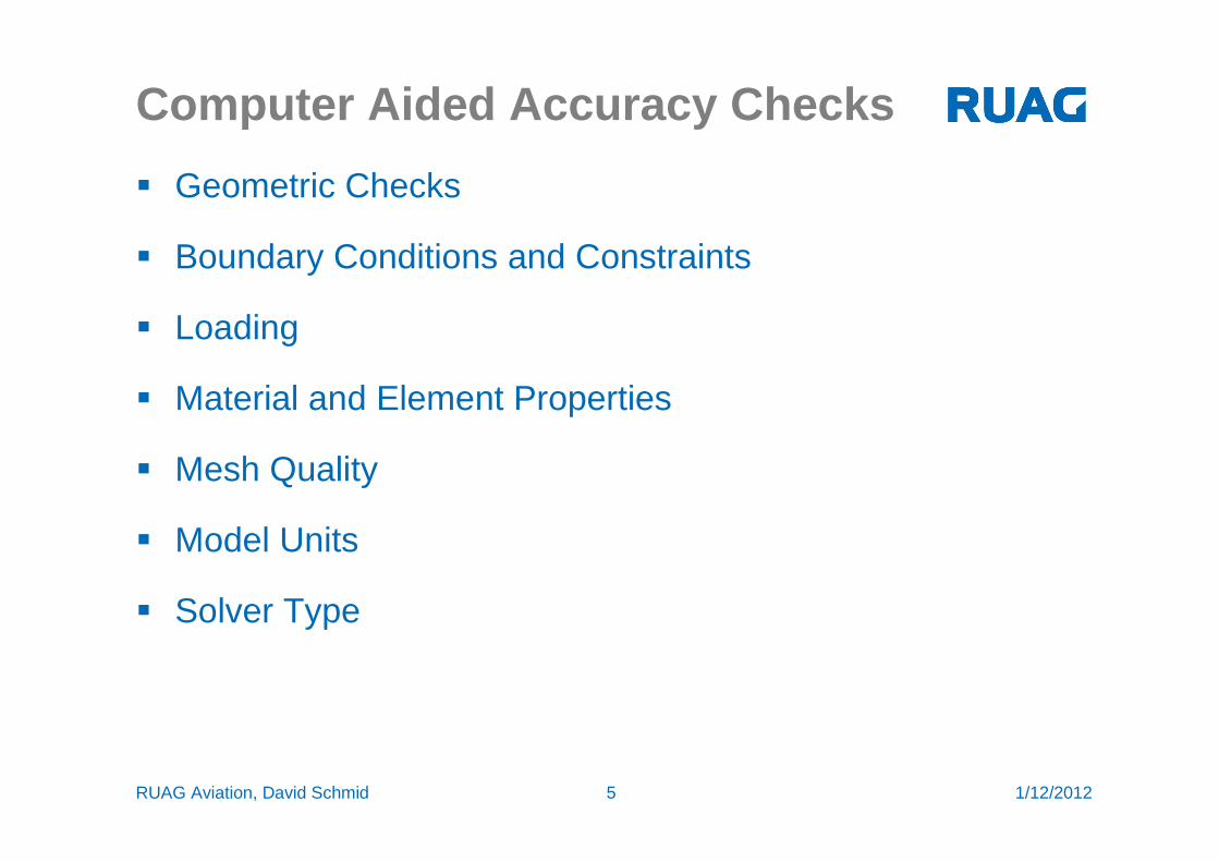
Computer Aided Accuracy Checks
� Geometric Checks
� Boundary Conditions and Constraints
� Loading
� Material and Element Properties
� Mesh Quality
� Model Units
� Solver Type

1/12/2012RUAG Aviation, David Schmid 6
Computer Aided Accuracy Checks
� Geometric Checks
� Dimensions: Check that the dimensions in the FE model correspond to the drawings, take a measurement in each dimensionx,y,z. Commonly, errors are introduced when importing CAD data
� Masses: Compare the overall mass in the model to the expected part / assembly mass
� Coordinate systems: Describe and check the most important coordinate systems (load systems, BC systems global A/C system, material systems). Are the axes correct? Some elements (e.g. RBEin Nastran) use the node coordinate system for the different element DOFs

1/12/2012RUAG Aviation, David Schmid 7
Computer Aided Accuracy Checks
� Boundary Conditions and constraints� Make sure that constraints are in the correct positions and the correct
DOFs are restrained
� After analysis run, check that SPC forces only occur at the mount points of the model
� Document and justify the boundary conditions in the report
� Loads� Check the direction, magnitude and location of applied loads. Common
errors are incorrect coordinate system associated with the loads, especially when importing loads from other sources
� Document the load cases occuring in the model and describe the loads contained therein
� The origin of the loads must be referenced or described in the validation report

1/12/2012RUAG Aviation, David Schmid 8
Computer Aided Accuracy Checks
� Material and Element Properties� Check that the material values correspond to the in the material
spec and include all the needed information (thermal expansion coefficient, reference temperature, density, etc). Check that the correct materials are assigned to the respective parts
� Verify beam element cross sections (area, moment of inertia, offsets etc)
� Mass and inertia properties
� Stiffnesses of spring elements
� Proper element use (thickness to area ratio for shell elements etc)
� Shell Element Thickness assignments. Note the reason if thicknesses different than the blueprint thicknesses are used

1/12/2012RUAG Aviation, David Schmid 9
Computer Aided Accuracy Checks
� Meshing� All surfaces should be appropriately covered
� Free Edges / Faces: Appropriate Preprocessor tools should be used to show free edges. Most common error is a zipper
� Duplicate nodes / elements: Free nodes can cause singularity errors while duplicate elements can change stress results
� Element normals should be aligned consistently

1/12/2012RUAG Aviation, David Schmid 10
Computer Aided Accuracy Checks
� Element Quality� Element quality limits depend on the solver used and can differ
greatly, nevertheless, warning and error limits should be established for each solver and at least the following parameters should be checked:
- Shell Elements: Aspect Ratio, Warp, Skew Angle, Taper Ratio
- Solid Elements: Aspect Ratio and Taper

1/12/2012RUAG Aviation, David Schmid 11
Computer Aided Accuracy Checks
� Units
� Consistent units should be used, whether in metric or in imperial
� The table below gives consistent units where 1 force unit = 1 mass unit * 1 acceleration unit and 1 acceleration unit = 1 length unit / (1 time unit)^2
� Nonconsistent units can lead to incorrect results e.g. when calculating eigenfrequencies

1/12/2012RUAG Aviation, David Schmid 12
Computer Aided Accuracy Checks
� Solver / Solution type
� Are the expected deformations small and is no contact or nonlinear material behaviour expected ?
� Linear models use the assumption of small displacements!
� Is the solver behaviour understood sufficiently for the model?
� Are the solver / solution types defined correctly in the input deck and are the parameters correct (e.g. no BAILOUT, -1 parameter defined in Nastran)
� Note the solver type and version used for verification in the report, it should be the same as for the analysis

1/12/2012RUAG Aviation, David Schmid 13
Mathematical Validity Checks
� Unit Displacement
� Free-Free Eigenmodes
� Unit Temperature Increase
� Dedicated Load Case
� Unit Gravity Load Case

1/12/2012RUAG Aviation, David Schmid 14
Mathematical Validity Checks
Unit enforced displacement and rotation check:
Expected Result:
Visualize the results in the postprocessor, the model should move one length unit as a rigid body.
Input:
Apply a unit displacement vector close to the CG of the model for each of the translational and rotational DOF of the model and calculate each resulting load case with the static solver
Purpose:
Verifies that no illegal grounding exists in the model.

1/12/2012RUAG Aviation, David Schmid 15
Mathematical Validity Checks
1/12/2012RUAG Aviation, David Schmid 16
Mathematical Validity Checks
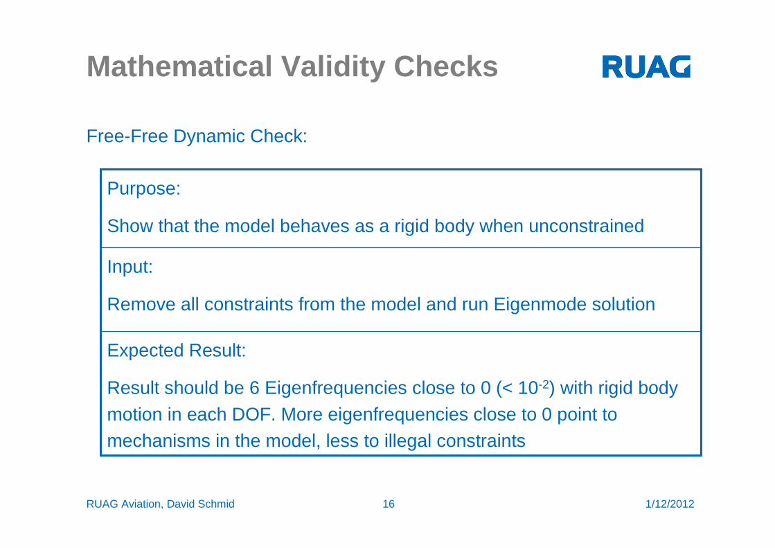
Free-Free Dynamic Check:
Expected Result:
Result should be 6 Eigenfrequencies close to 0 (< 10-2) with rigid body motion in each DOF. More eigenfrequencies close to 0 point to mechanisms in the model, less to illegal constraints
Input:
Remove all constraints from the model and run Eigenmode solution
Purpose:
Show that the model behaves as a rigid body when unconstrained

1/12/2012RUAG Aviation, David Schmid 17
Mathematical Validity Checks

1/12/2012RUAG Aviation, David Schmid 18
Mathematical Validity Checks
Unit Gravity Loading:
Expected Result:
Result should show no large displacements for linear solutions. Additionally, forces and moments should only be obtained at the constraint locations. The forces should add up to the total weight for the model in the input loading direction and should be zero for all other directions
Input:
Apply constraints and unit gravity loading in each translational DOF
Purpose:
Verify that the model provides meaningful results under inertial loading

1/12/2012RUAG Aviation, David Schmid 19
Mathematical Validity Checks
Dedicated Load Case:
Expected Result:
Deformations should be small. Constraint and applied forces should be in equilibrium. No inappropriate singularities should exist in the model. The normalized value of residual loading should be small (e.g. NastranEpsilon < 10-8)
Input:
Use realistic load case and appropriate constraints
Purpose:
Check the model for singularities, small deformations, force equilibrium and residuals

1/12/2012RUAG Aviation, David Schmid 20
Force EquilibriumOLOAD Resultant
SUBCASE/ LOAD
DAREA ID TYPE T1 T2 T3 R1 R2 R3
0 7 FX -1.698315E-02 ---- ---- ---- -5.081908E+06 -9.896120E+01
FY ---- -6.412354E-03 ---- -7.514633E+01 ---- 9.941594E+01
FZ ---- ---- -7.780754E-03 5.791170E+01 5.095341E+06 ----
MX ---- ---- ---- 9.465669E+00 ---- ----
MY ---- ---- ---- ---- -1.205979E+04 ----
MZ ---- ---- ---- ---- ---- -3.300800E+00
TOTALS -1.698315E-02 -6.412354E-03 -7.780754E-03 -7.768963E+00 1.372500E+03 -2.846062E+00
0 SPCFORCE RESULTANT
SUBCASE/ LOAD
DAREA ID TYPE T1 T2 T3 R1 R2 R3
0 7 FX 1.698312E-02 ---- ---- ---- 1.227183E+00 -7.131656E-01
FY ---- 6.412358E-03 ---- -4.633506E-01 ---- 3.559231E+00
FZ ---- ---- 7.780789E-03 8.232316E+00 -1.374047E+03 ----
MX ---- ---- ---- 0.000000E+00 ---- ----
MY ---- ---- ---- ---- 0.000000E+00 ----
MZ ---- ---- ---- ---- ---- 0.000000E+00
TOTALS 1.698312E-02 6.412358E-03 7.780789E-03 7.768965E+00 -1.372819E+03 2.846065E+00

1/12/2012RUAG Aviation, David Schmid 21
Normalized Residual Loading
Pu
PuT
T
⋅⋅= δε
The normalized Residual Loading is defined as
with
PKuP −=δ
The linear static solution solves the equation
PKu =

1/12/2012RUAG Aviation, David Schmid 22
Singularities
� Singularities in linear analysis can stem from different sources:
� Missing Elements
� 2D Shells with normal rotation unconstrained (Nastran)
� Solid model with rotational DOFs at the corners unconstrained (Nastran)
� Incorrect beam offset modeling
� Incorrect multipoint constraints
� Mechanisms and free bodies
� Low rotational stiffnesses
� Abrupt stiffness changes
� Singularities generally decrease the accuracy of the model and should be corrected or constrained

1/12/2012RUAG Aviation, David Schmid 23
Mathematical Validity Checks
Unit Temperature Increase:
Expected Result:
Strains / stresses throughout the model should be zero. Compare distortion with hand calculation.
Input:
Create kinematic mount for the model (one node restricted in all 6 DOF) and set all expansion coefficients and reference temperatures to the same value. Apply a one unit temperature increase.
Purpose:
Verifies that the model provides accurate displacements due to temperature loading.

1/12/2012RUAG Aviation, David Schmid 24
FEM Quality Report
� The purpose of the FEM ValidationReport is to document the checks outlined in this presentation and to describe the model in such a detail that another engineer can understand the model
� For smaller models, the model description is included in thestress analysis report and a FEM check form is filled out

1/12/2012RUAG Aviation, David Schmid 25
Further Reading
1.) MSC Nastran Linear Static Analysis Users Guide, MSC, 2008
2.) Finite Element Modeling Continuous Improvement (FEMCI), Section Validity Checks, available at http://femci.gsfc.nasa.gov/validitychecks/

1/12/2012RUAG Aviation, David Schmid 26
Validity Checks
Do not blindly trust the model, use common sense when evaluating the results

1/12/2012RUAG Aviation, David Schmid 27
Thank you for your attention!