Embed Size (px)
Citation preview

© 2011 Collier Research Corp.
Collier Research Corporation Hampton, VA
FEM: NASTRAN Imported and Exported Data Including PCOMP Laminates

© 2011 Collier Research Corporation
THE AP1 TRAINING FEM
(Refer to the HyperSizer ProTM Tutorials online for more information)

© 2011 Collier Research Corporation
INIT MASTER(S) ID S:\Hyper,MSC.v SOL SESTATICS TIME 10000 CEND SUBCASE 101 SUBTITLE = Wing Pressure FORCE = ALL SPC = 100 LOAD = 101 SUBCASE 102 SUBTITLE = Internal Tank Pressure FORCE = ALL SPC = 100 LOAD = 102 SUBCASE 103 SUBTITLE = Fuselage Bending FORCE = ALL SPC = 100 LOAD = 103 SUBCASE 201 SUBTITLE = Aero Heating FORCE = ALL SPC = 100 TEMP(LOAD) = 201 BEGIN BULK $ PARAM,POST,-1 PARAM,OGEOM,NO PARAM,AUTOSPC,YES PARAM,MAXRATIO,1.E+8 PARAM,GRDPNT,0
$ Include applied load PLOAD4 and FORCE data INCLUDE 'Ap1.LOAD' $ Include applied thermal TEMPP and TEMPRB data INCLUDE 'Ap1.TEMP' $ Include boundary condition SPC data INCLUDE 'Ap1.SPCS' $ Include model Grids INCLUDE 'Ap1.GRID' $ Include model CQUAD4 and CTRIA3 elements INCLUDE 'Ap1.SHEL' $ Include Patran generated Property Name PSET data $ Read by HyperSizer to assign character strings to Component IDs INCLUDE 'Ap1.PSET' $ Include HyperSizer generated property and material data to represent $ panel thermoelastic stiffness changes that occur during sizing $ iterations.Provides the updated PSHELL, PBAR, MAT2, and MAT1 data. $ *_00=starting point properties, *.01=first sizing iteration INCLUDE 'Ap1_00.PM1' $ Include HyperSizer generated CBAR beam element data $ Provides beam offset vectors to represent neutral axis shifts that $ occur during sizing iterations. $ *._00=starting point properties, *.01=first sizing iteration INCLUDE 'Ap1_00.CL1' ENDDATA
The Complete FEM Input File

© 2011 Collier Research Corporation
INIT MASTER(S) ID S:\Hyper,MSC.v SOL SESTATICS TIME 10000 CEND SUBCASE 101 SUBTITLE = Wing Pressure FORCE = ALL SPC = 100 LOAD = 101 SUBCASE 102 SUBTITLE = Internal Tank Pressure FORCE = ALL SPC = 100 LOAD = 102 SUBCASE 103 SUBTITLE = Fuselage Bending FORCE = ALL SPC = 100 LOAD = 103 SUBCASE 201 SUBTITLE = Aero Heating FORCE = ALL SPC = 100 TEMP(LOAD) = 201 BEGIN BULK
Note: Must generate element forces in the *.F06 File.
Three Mechanical Load Sets imported.
One Thermal Load Set Imported.
FEM Case Control

© 2011 Collier Research Corporation
$ Applied load PLOAD4 and FORCE data INCLUDE 'Ap1.LOAD‘ $ Applied thermal TEMPP and TEMPRB data INCLUDE 'Ap1.TEMP‘ $ Boundary condition SPC data INCLUDE 'Ap1.SPCS‘ $ model Grids INCLUDE 'Ap1.GRID'
PLOAD4 pressure data is imported.
TEMPP & TEMPRB temperature data is imported.
GRID data is imported.
$ Include model CQUAD4 and CTRIA3 elements INCLUDE 'Ap1.SHEL‘
Element Shell data is imported.
Beam – Element Offset Vectors Created by HyperSizer
$ HyperSizer generated CBAR beam element data $ Provides beam offset vectors to represent neutral axis $ shifts that occur during sizing iterations. $ *._00=starting point properties, *.01=first sizing $ iteration properties, etc. INCLUDE 'Ap1_00.CL1‘ ENDDATA
Properties and Materials Created by HyperSizer
$ HyperSizer generated property and material data to $ represent panel thermoelastic stiffness changes that $ occur during sizing iterations. Provides the updated $ PSHELL, PBAR, MAT2, and MAT1 data. $ *_00=starting point properties, *.01=first sizing $ iteration properties, etc. INCLUDE 'Ap1_00.PM1‘
PATRAN PSET data is imported.
$ Patran generated Property Name PSET data $ Read by HyperSizer to assign character strings to $ Component IDs INCLUDE 'Ap1.PSET‘
FEM Bulk Data
© 2011 Collier Research Corporation
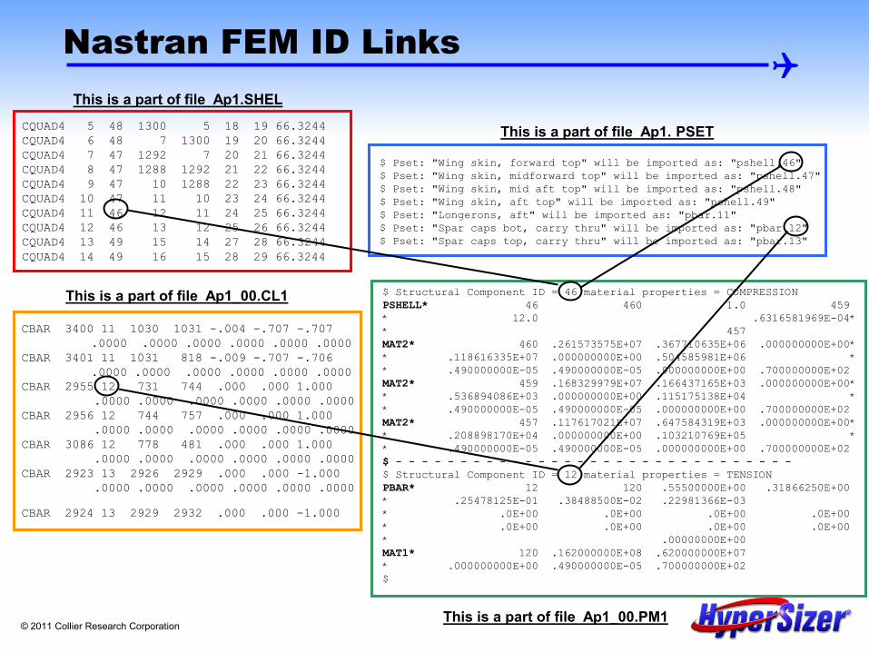
CQUAD4 5 48 1300 5 18 19 66.3244 CQUAD4 6 48 7 1300 19 20 66.3244 CQUAD4 7 47 1292 7 20 21 66.3244 CQUAD4 8 47 1288 1292 21 22 66.3244 CQUAD4 9 47 10 1288 22 23 66.3244 CQUAD4 10 47 11 10 23 24 66.3244 CQUAD4 11 46 12 11 24 25 66.3244 CQUAD4 12 46 13 12 25 26 66.3244 CQUAD4 13 49 15 14 27 28 66.3244 CQUAD4 14 49 16 15 28 29 66.3244
This is a part of file Ap1.SHEL
$ Pset: "Wing skin, forward top" will be imported as: "pshell.46" $ Pset: "Wing skin, midforward top" will be imported as: "pshell.47" $ Pset: "Wing skin, mid aft top" will be imported as: "pshell.48" $ Pset: "Wing skin, aft top" will be imported as: "pshell.49" $ Pset: "Longerons, aft" will be imported as: "pbar.11" $ Pset: "Spar caps bot, carry thru" will be imported as: "pbar.12" $ Pset: "Spar caps top, carry thru" will be imported as: "pbar.13"
This is a part of file Ap1. PSET
$ Structural Component ID = 46 material properties = COMPRESSION PSHELL* 46 460 1.0 459 * 12.0 .6316581969E-04* * 457 MAT2* 460 .261573575E+07 .367710635E+06 .000000000E+00* * .118616335E+07 .000000000E+00 .504585981E+06 * * .490000000E-05 .490000000E-05 .000000000E+00 .700000000E+02 MAT2* 459 .168329979E+07 .166437165E+03 .000000000E+00* * .536894086E+03 .000000000E+00 .115175138E+04 * * .490000000E-05 .490000000E-05 .000000000E+00 .700000000E+02 MAT2* 457 .117617021E+07 .647584319E+03 .000000000E+00* * .208898170E+04 .000000000E+00 .103210769E+05 * * .490000000E-05 .490000000E-05 .000000000E+00 .700000000E+02 $ - - - - - - - - - - - - - - - - - - - - - - - - - - - - - - - $ Structural Component ID = 12 material properties = TENSION PBAR* 12 120 .55500000E+00 .31866250E+00 * .25478125E-01 .38488500E-02 .22981366E-03 * .0E+00 .0E+00 .0E+00 .0E+00 * .0E+00 .0E+00 .0E+00 .0E+00 * .00000000E+00 MAT1* 120 .162000000E+08 .620000000E+07 * .000000000E+00 .490000000E-05 .700000000E+02 $
This is a part of file Ap1_00.PM1
CBAR 3400 11 1030 1031 -.004 -.707 -.707 .0000 .0000 .0000 .0000 .0000 .0000 CBAR 3401 11 1031 818 -.009 -.707 -.706 .0000 .0000 .0000 .0000 .0000 .0000 CBAR 2955 12 731 744 .000 .000 1.000 .0000 .0000 .0000 .0000 .0000 .0000 CBAR 2956 12 744 757 .000 .000 1.000 .0000 .0000 .0000 .0000 .0000 .0000 CBAR 3086 12 778 481 .000 .000 1.000 .0000 .0000 .0000 .0000 .0000 .0000 CBAR 2923 13 2926 2929 .000 .000 -1.000 .0000 .0000 .0000 .0000 .0000 .0000
CBAR 2924 13 2929 2932 .000 .000 -1.000
This is a part of file Ap1_00.CL1
Nastran FEM ID Links

© 2011 Collier Research Corporation
Four ways to model stiffened panels
1) Planar 2D mesh with stiffeners smeared in shell elements
3) Discrete 3D mesh using shell elements for both the facesheet and stiffener web
4) Discrete 3D mesh using solid elements for both the facesheet and stiffener web
2) Planar 2D mesh with stiffeners modeled with beam elements
Approach 1 is the preferred approach for a HyperSizer analysis/sizing which allows users to swap out any panel concepts on the fly to be accurately represented in a FEM
Airframe Fuselage Panel

© 2011 Collier Research Corporation
HyperSizer’s Panel Formulations Accurately Couple with Planar FEM Meshes
With a single plane of shell elements, HyperSizer is able to get accurate mechanical and thermal stress/strain fields throughout the panel depth for general FEM loading environments This permits quick evaluation of other panel concepts without the need of changing the FEM mesh

© 2011 Collier Research Corporation
$ Structural Component ID = 46 material properties = COMPRESSION PSHELL* 46 460 1.0 459 * 12.0 .6316581969E-04* * 457 MAT2* 460 .261573575E+07 .367710635E+06 .000000000E+00* * .118616335E+07 .000000000E+00 .504585981E+06 * * .490000000E-05 .490000000E-05 .000000000E+00 .700000000E+02 MAT2* 459 .168329979E+07 .166437165E+03 .000000000E+00* * .536894086E+03 .000000000E+00 .115175138E+04 * * .490000000E-05 .490000000E-05 .000000000E+00 .700000000E+02 MAT2* 457 .117617021E+07 .647584319E+03 .000000000E+00* * .208898170E+04 .000000000E+00 .103210769E+05 * * .490000000E-05 .490000000E-05 .000000000E+00 .700000000E+02 $ Structural Component ID = 12 material properties = TENSION PBAR* 12 120 .55500000E+00 .31866250E+00 * .25478125E-01 .38488500E-02 .22981366E-03 * .0E+00 .0E+00 .0E+00 .0E+00 * .0E+00 .0E+00 .0E+00 .0E+00 * .00000000E+00 MAT1* 120 .162000000E+08 .620000000E+07 * .000000000E+00 .490000000E-05 .700000000E+02 $
HyperSizer Generates FEM PSHELL & MAT2 Data for any Panel Concept
After sizing, HyperSizer creates FEM materials and properties to represent any panel concept with a single plane of shell CQUAD4 and/or CTRI3 elements and any beam concept with a line of CBAR elements.
Each MAT2 represents a 3x3 stiffness matrix: MAT ID 460 = Aij (membrane) 459 = Dij (bending) 457 = Bij (coupling) (sandwich concepts also include the 2x2 transverse shear terms)
The PBAR lists the beam properties such as area, moments of inertia, etc.

© 2011 Collier Research Corporation
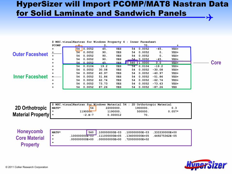
HyperSizer can also import and export FEM PCOMP/MAT8 materials
Inner Facesheet [-87/87/-74/74/-63/63/-52/52/-41/41/-30/30/-19/19]
Outer Facesheet [45/-45/90/0/90/0/90/-45/45]
normals
A typical FEM of a composite structure may have hundreds of individual Nastran PCOMPs defining the laminates. In this fuselage barrel example, the honeycomb structure is modeled as a single plane of shell elements with a PCOMP. The honeycomb core is included as a layer in the PCOMP.
Honeycomb Core, t=1"
Although this sandwich panel is unsymmetric, both the FEA and HyperSizer consistently default to the midplane of the panel rather than the neutral axis or midplane of the core. If the FEM PCOMP includes an offset, it will be imported into HyperSizer. This capability is described later.
© 2011 Collier Research Corporation
$ MSC.visualNastran for Windows Property 4 : Inner Facesheet PCOMP 4 0. 70. + + 54 0.0052 45. YES 54 0.0052 -45. YES+ + 54 0.0052 90. YES 54 0.0052 0. YES+ + 54 0.0052 90. YES 54 0.0052 0. YES+ + 54 0.0052 90. YES 54 0.0052 -45. YES+ + 54 0.0052 45. YES 560 1.0000 0.0 YES+ + 54 0.0104 19.2 YES 54 0.0104 -19.2 YES+ + 54 0.0052 30.08 YES 54 0.0052 -30.08 YES+ + 54 0.0052 40.97 YES 54 0.0052 -40.97 YES+ + 54 0.0052 51.86 YES 54 0.0052 -51.86 YES+ + 54 0.0052 62.74 YES 54 0.0052 -62.74 YES+ + 54 0.0052 73.73 YES 54 0.0052 -73.63 YES+ + 54 0.0052 87.26 YES 54 0.0052 -87.26 YES $ MSC.visualNastran for Windows Material 54 : 2D Orthotropic Material MAT8* 54 22000000. 1900000. 0.3 * 1190000. 1190000. 500000. 0.057* * -2.E-7 0.000012 70. MAT8* 560 .100000000E-03 .100000000E-03 .333330000E+00 * .100000000E-03 .111000000E+05 .134000000E+05 .449275362E-05 * .000000000E+00 .000000000E+00 .720000000E+02 *
Inner Facesheet
Outer Facesheet
HyperSizer will Import PCOMP/MAT8 Nastran Data for Solid Laminate and Sandwich Panels
Core
2D Orthotropic Material Property
Honeycomb Core Material
Property

© 2011 Collier Research Corporation
PCOMP Loaded into HyperSizer as a Honeycomb Sandwich Component
The PCOMP is imported into HyperSizer and automatically loaded into the Sizing Form as a honeycomb sandwich component.
Outer Facesheet
Inner Facesheet
Core

© 2011 Collier Research Corporation
$ $ Structural Component ID = 4 material properties = TENSION MAT8* 54 .217500000E+08 .190000000E+07 .300000000E+00 * .119000000E+07 .119000000E+07 .119000000E+07 .147515528E-03 * -.300000000E-06 .754000000E-05 .720000000E+02 .105600000E+06 * .795500000E+05 .912000000E+04 .703000000E+04 .158000000E+05 MAT8* 560 .100000000E-03 .100000000E-03 .333330000E+00 * .100000000E-03 .111000000E+05 .134000000E+05 .449275362E-05 * .000000000E+00 .000000000E+00 .720000000E+02 * PCOMP 4 -1.0832 .136E+03 HOFF 72.0 + 54 0.0052 45. YES 54 0.0052 -45. YES+ + 54 0.0052 90. YES 54 0.0052 0. YES+ + 54 0.0052 90. YES 54 0.0052 0. YES+ + 54 0.0052 90. YES 54 0.0052 -45. YES+ + 54 0.0052 45. YES 560 1.0000 0.0 YES+ + 54 0.0104 19.2 YES 54 0.0104 -19.2 YES+ + 54 0.0052 30.08 YES 54 0.0052 -30.08 YES+ + 54 0.0052 40.97 YES 54 0.0052 -40.97 YES+ + 54 0.0052 51.86 YES 54 0.0052 -51.86 YES+ + 54 0.0052 62.74 YES 54 0.0052 -62.74 YES+ + 54 0.0052 73.73 YES 54 0.0052 -73.63 YES+ + 54 0.0052 87.26 YES 54 0.0052 -87.26 YES
Inner Facesheet
Outer Facesheet
HyperSizer Automatically Generates PCOMP/MAT8 Nastran Data Based on Optimized Design
Core
2D Orthotropic Material Property
Honeycomb Core

© 2011 Collier Research Corporation
IMPORT PROCESS FOR PCOMP LAMINATES AND MAT8 MATERIALS FROM THE FEM

© 2011 Collier Research Corporation
Automatic Importing of PCOMPs to create Laminates and Honeycomb Sandwiches
• PCOMP properties in a finite element model can be automatically imported into HyperSizer as layup and laminate materials.
• For honeycomb or laminate components, PCOMPs will be used to define sizing groups and set up all sizing parameters (materials, dimensions, etc.)
• If a honeycomb core layer is found, HyperSizer will import the PCOMP as a honeycomb sandwich component.
• If a material exists in the HyperSizer database that corresponds to a MAT8 or MAT1 card, it will be associated with that material in the FEM.
• Offsets defined on PCOMP cards will automatically be imported and included as a reference plane offset on the Sizing form.

© 2011 Collier Research Corporation
Summary Steps: Importing PCOMPs with MAT1 or MAT8 into HyperSizer
1. Create Materials in the HyperSizer Database corresponding to MAT1 and MAT8 cards in the FEM
2. Select the PCOMP Import Option on the Project Setup form 3. Import the FEM 4. Open the Laminate Editor to view the generated composite laminates
and material ply assignments 5. Open the Sizing form to analyze the components and obtain margins of
safety
Each step will be discussed in detail on the following slides.

© 2011 Collier Research Corporation
Example problem to illustrate PCOMP import process
Top Facesheet (tape) [45/-45/0/90/0/90/45/-45/0]s
Bottom Facesheet (tape) [45/-45/0/90/0/90/45/-45/0]s
Honeycomb Core, t=2.5"
MAT8* 450 .233502500E+08 .165047100E+07 .320000000E+00 * .749818700E+06 .749818700E+06 .629441600E+06 .148550725E-03 * -.100000000E-06 .150000000E-04 .720000000E+02 * MAT8* 560 .100000000E-03 .100000000E-03 .333330000E+00 * .100000000E-03 .170000000E+05 .430000000E+05 .615424431E-05 * .000000000E+00 .000000000E+00 .720000000E+02 * PCOMP 39 .149E+03 HOFF 72.0 + 450 .0050 45.000 450 .0050 -45.000 + 450 .0050 .000 450 .0050 90.000 + 450 .0050 .000 450 .0050 90.000 + 450 .0050 45.000 450 .0050 -45.000 + 450 .0050 .000 450 .0050 .000 + 450 .0050 -45.000 450 .0050 45.000 + 450 .0050 90.000 450 .0050 .000 + 450 .0050 90.000 450 .0050 .000 + 450 .0050 -45.000 450 .0050 45.000 + 560 2.5000 .000 450 .0050 45.000 + 450 .0050 -45.000 450 .0050 .000 + 450 .0050 90.000 450 .0050 .000 + 450 .0050 90.000 450 .0050 45.000 + 450 .0050 -45.000 450 .0050 .000 + 450 .0050 .000 450 .0050 -45.000 + 450 .0050 45.000 450 .0050 90.000 + 450 .0050 .000 450 .0050 90.000 + 450 .0050 .000 450 .0050 -45.000 + 450 .0050 45.000
Shown here is a different sandwich design than the previous example. It is a honeycomb with composite fabric facesheets. The PCOMP has 18 layers representing the bottom facesheet (green outline), 18 for the top facesheet (blue outline) and one ply representing the core (purple outline).

© 2011 Collier Research Corporation
Step 1a: Create Materials in the HyperSizer Database corresponding to FEM MAT1 and MAT8 cards in the FEM
For every MAT1 and MAT8 card in the FEM, create a material in the HyperSizer database and at the END of the material name, append the string KMAT8%<MATID> For example, the following MAT8 card has MATID=450. MAT8* 450 .233502500E+08 .165047100E+07 .320000000E+00 * .749818700E+06 .749818700E+06 .629441600E+06 .148550725E-03 * -.100000000E-06 .150000000E-04 .720000000E+02 *
Create a material in the HyperSizer database. The material name is arbitrary, but it must end with “KMAT8%450” in order to establish the association between the HyperSizer material and the Nastran material. Note that this material is not created automatically. It must be created using processes described in the Material Manager User Manual.
© 2011 Collier Research Corporation
Step 1b: Create Materials in the HyperSizer Database corresponding to FEM MAT1 and MAT8 cards in the FEM
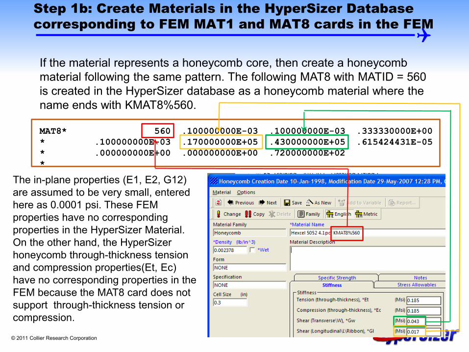
If the material represents a honeycomb core, then create a honeycomb material following the same pattern. The following MAT8 with MATID = 560 is created in the HyperSizer database as a honeycomb material where the name ends with KMAT8%560. MAT8* 560 .100000000E-03 .100000000E-03 .333330000E+00 * .100000000E-03 .170000000E+05 .430000000E+05 .615424431E-05 * .000000000E+00 .000000000E+00 .720000000E+02 * The in-plane properties (E1, E2, G12)
are assumed to be very small, entered here as 0.0001 psi. These FEM properties have no corresponding properties in the HyperSizer Material. On the other hand, the HyperSizer honeycomb through-thickness tension and compression properties(Et, Ec) have no corresponding properties in the FEM because the MAT8 card does not support through-thickness tension or compression.

© 2011 Collier Research Corporation
Step 2a: Select the PCOMP Import Option on the Project Setup Form
• The first flag to turn on is “Import PCOMP properties and create layups and laminates.” This flag tells HyperSizer to read the PCOMPs from the FEM and create layup and laminate materials in the database.

© 2011 Collier Research Corporation
Step 2b: Select the PCOMP Import Option on the Project Setup Form
• The second flag to activate, “Automatically create groups and assign components from imported PCOMPs,” tells HyperSizer that for every PCOMP imported from the FEM, create a Sizing Group and assign the component corresponding to the imported PCOMP into that group. Every group created in this way will have exactly one component.

© 2011 Collier Research Corporation
Step 3: Import the FEM
• HyperSizer will read PCOMPs and create appropriate laminates and layups based on the PCOMP definition.
• If materials are in the FEM that do not have corresponding materials in HyperSizer, the following message will be displayed.
• In this example, no material with ID = KMAT8%251 exists in the HyperSizer
database, therefore this message tells us that a material needs to be created to complete the laminate for component 40.
• If this occurs, the error is not fatal, however these missing materials must be manually applied to the created components after import is completed.

© 2011 Collier Research Corporation
Step 4a: Open the Laminate Editor to view the generated composite laminates
During import into HyperSizer, for the following PCOMP (as defined in the FEM), laminates and layups will automatically be created that contain the ply sequence, materials, and thicknesses. MAT8* 450 .233502500E+08 .165047100E+07 .320000000E+00 * .749818700E+06 .749818700E+06 .629441600E+06 .148550725E-03 * -.100000000E-06 .150000000E-04 .720000000E+02 * MAT8* 560 .100000000E-03 .100000000E-03 .333330000E+00 * .100000000E-03 .170000000E+05 .430000000E+05 .615424431E-05 * .000000000E+00 .000000000E+00 .720000000E+02 * PCOMP 39 .149E+03 HOFF 72.0 + 450 .0050 45.000 450 .0050 -45.000 + 450 .0050 .000 450 .0050 90.000 + 450 .0050 .000 450 .0050 90.000 + 450 .0050 45.000 450 .0050 -45.000 + 450 .0050 .000 450 .0050 .000 + 450 .0050 -45.000 450 .0050 45.000 + 450 .0050 90.000 450 .0050 .000 + 450 .0050 90.000 450 .0050 .000 + 450 .0050 -45.000 450 .0050 45.000 + 560 2.5000 .000 450 .0050 45.000 + 450 .0050 -45.000 450 .0050 .000 + 450 .0050 90.000 450 .0050 .000 + 450 .0050 90.000 450 .0050 45.000 + 450 .0050 -45.000 450 .0050 .000 + 450 .0050 .000 450 .0050 -45.000 + 450 .0050 45.000 450 .0050 90.000 + 450 .0050 .000 450 .0050 90.000 + 450 .0050 .000 450 .0050 -45.000 + 450 .0050 45.000
Composite Ply Data
Core Data
Bottom Facesheet
Top Facesheet
2.5” Core Material with ID = 560
© 2011 Collier Research Corporation
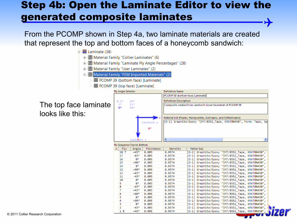
Step 4b: Open the Laminate Editor to view the generated composite laminates From the PCOMP shown in Step 4a, two laminate materials are created that represent the top and bottom faces of a honeycomb sandwich:
The top face laminate looks like this:

© 2011 Collier Research Corporation
Step 4c: Open the Laminate Editor to view the generated composite layups
In addition to the Laminates, two Layup materials are created:
The top face layup looks like this: A HyperSizer “Layup” material type is a ply sequence without an associated orthotropic material. Layups are useful for sizing structures where combinations of layups and ply materials can be evaluated to get an optimal design. The PCOMP import process creates both layup and laminate materials to give the user the choice of the most convenient modeling technique.

© 2011 Collier Research Corporation
Step 5a: Open the Sizing form to analyze the components and obtain margins-of-safety
A Group/Component will be created in HyperSizer with the following layups/materials and dimensions: First, the “Top Face” variable will contain the layup called “PCOMP 39 (top face) [Layup]” along with the orthotropic material created in Step 1, KMAT8%450.
Green Color = HyperSizer Layup
Black Color = HyperSizer Orthotropic Ply Material

© 2011 Collier Research Corporation
Step 5b: Open the Sizing form to analyze the components and obtain margins-of-safety
The “Core” variable will be filled out with the following material and dimension. Note the minimum and maximum dimensions are set to the thickness of the core from the PCOMP and the material included is the honeycomb material defined in Step 1.
Core Thickness of 2.5” as imported from the Nastran PCOMP
Purple Color = HyperSizer Honeycomb Material

© 2011 Collier Research Corporation
Step 5c: Open the Sizing form to analyze the components and obtain margins-of-safety
Finally, the lower face variable contains a layup called “PCOMP 39 (bottom face) [Layup]” along with the same orthotropic material created in Step 1 (KMAT8%450).
Note here that the layup material included for the bottom face is not the same layup included for the top face. When the overall sandwich PCOMP was imported, it was split into two separate layups representing the top and bottom faces. The name of each layup indicates that it was created from PCOMP 39 with either “top face” or “bottom face” in parentheses. The KMAT8%450 orthotropic material is the same for both faces.

© 2011 Collier Research Corporation
Creation of Honeycomb Sandwich Components, Notes Slide 1
• While processing a PCOMP, HyperSizer analyzes each layer and if that layer is determined to be a honeycomb core, HyperSizer will treat this PCOMP as a honeycomb sandwich rather than as a bare laminate.
• Rules for determining if a layer is a honeycomb material: • The current layer is not the first or last layer in the PCOMP. • The thickness of this layer is greater than ten times the thickness of the
previous layer. • The transverse shear stiffness (G1z) of the material of this layer is greater
than the in-plane stiffness (E1) of this material. This should never happen for a composite ply material but is very common for a honeycomb which has very little in-plane stiffness.

© 2011 Collier Research Corporation
Creation of Honeycomb Sandwich Components, Notes Slide 2
• If all of these rules are satisfied, HyperSizer splits the PCOMP into three separate objects when importing into HyperSizer.
• All layers above the core (layers i+1 through N) will be treated as a “Top Face” laminate.
• All layers below the core (layers 1 through i-1) will be treated as a “Bottom Face” laminate.
• The current layer (layer i) will be used as the core object in HyperSizer. • After sizing, HyperSizer will “reassemble” the honeycomb back into a single
PCOMP and MAT8 combination when exporting to the *.PM1 file for iteration with FEA.

© 2011 Collier Research Corporation
Import of Nastran Offsets, Notes Slide 3
The Nastran offset is defined FROM the grid point TO the bottom surface of the laminate. In the examples shown here, where grid points are defined on the OML, the Nastran offset is equal to negative overall thickness. Nastran Offset = -2.662
Element Normal
The HyperSizer offset is defined FROM the default reference plane TO the grid points. For laminates or sandwiches, the default reference plane is the mid-plane. Therefore, the offset will be positive overall thickness divided by two. HyperSizer Offset = +1.331
Nastran Offset
HyperSizer Offset
Element Normal
Height = 2.662”

© 2011 Collier Research Corporation
Import of Nastran Offsets, Notes Slide 4
HyperSizer reads the offsets from the PCOMP card and automatically converts the offset from Nastran format to HyperSizer format. PCOMP 40 -2.662.288E-05.149E+03 HOFF 72.0 + 250 .0081 45.000 250 .0081 .000 + 250 .0081 45.000 250 .0081 45.000 + 250 .0081 45.000 250 .0081 45.000 + 250 .0081 45.000 250 .0081 45.000 + 250 .0081 .000 250 .0081 45.000 + 560 2.5000 .000 250 .0081 45.000 + 250 .0081 .000 250 .0081 45.000 + 250 .0081 45.000 250 .0081 45.000 + 250 .0081 45.000 250 .0081 45.000 + 250 .0081 45.000 250 .0081 .000 + 250 .0081 45.000
The imported offset can be viewed on the Options tab of the Sizing form. For the example shown, the Nastran offset of -2.662" is converted to a HyperSizer offset of 1.331,” (** as paired with the selection of panel midplane as reference plane). Note that offsets on individual element cards are not considered, only offsets on PCOMP cards are read and converted on the Sizing form.

© 2011 Collier Research Corporation
Limitations
• Import of PCOMP/MAT8 into HyperSizer layups/laminates and group creation works only for honeycomb or solid laminates. If a component is to be defined as a stiffened panel (uniaxial, hat, orthogrid, etc.), this import method will not work.
• If the property in Nastran is defined with a PSHELL/MAT1 or PSHELL/MAT2, then no material, laminate, layup, or group will be created.
• If a material has not been created in HyperSizer with the KMAT% designation required for a PCOMP, then HyperSizer will create a “Layup” material (ply sequence with no material), however, HyperSizer will not attempt to create a “Laminate” material (ply sequence with materials).

© 2011 Collier Research Corporation
Limitations • If a PCOMP contains multiple composite materials or a combination of
composite and metallic materials (i.e. a hybrid laminate), then a “Laminate” material is created and assigned to the created group. However, no “Layup” material is created. For a hybrid laminate, if a MAT8% or MAT1% required material is missing from the HyperSizer database, then no laminate or layup will be created.
• MAT8 or MAT1 cards that are not used by PCOMP or PBARL cards in the FEM will be ignored by HyperSizer.
• Reference plane offsets that are defined on element cards will be ignored by HyperSizer. HyperSizer will only consider offsets if they are defined on the PCOMP cards.

© 2011 Collier Research Corporation
IMPORT PROCESS FOR PBARL BEAM GEOMETRY AND MAT1 MATERIALS FROM THE FEM

© 2011 Collier Research Corporation
Steps for Importing PBARLs with MAT1 Materials into HyperSizer
1. Create Materials in the HyperSizer database corresponding to MAT1 cards in the FEM.
2. Select the PCOMP/PBARL Import Options on the Project Setup form.
3. Import the FEM. 4. Open the Sizing form to analyze the components and obtain margins of
safety. Each step will be discussed on the following slides.
The process of importing the PBARL is similar to the import of PCOMPs. However, no laminates or layups are created, so examining imported layups is not included here.

© 2011 Collier Research Corporation
Example problem to illustrate PBARL import process
$ Al 7075 Room Temperature Property MAT1 180 .104E+8 .4E+7 0. .123E-4 .70E+2 $ I-Beam Ringframe PBARL 18 180 MSCBML0 I + 6.0 2.0 4.0 .09 .15 .15 .369E-3
The example problem is a metallic I-Beam where the upper and lower flange, and web thicknesses and widths are all independent.
Height = 6.0" Bottom Flange Width = 2.0" Top Flange Width = 4.0" Web Thickness = 0.09" Bottom Flange Thickness = 0.15" Top Flange Thickness = 0.15"
.09
.15
.15
2
4
6

© 2011 Collier Research Corporation
Step 1a: Create Materials in the HyperSizer Database corresponding to FEM MAT1 and MAT8 cards in the FEM
For every MAT1 card in the FEM, create a material in the HyperSizer database and at the END of the material name, append the string KMAT1%<MATID> For example, the following MAT1 card has MATID=180,
$ Al 7075 Room Temperature Property MAT1 180 .104E+8 .4E+7 0. .123E-4 .70E+2
Create a material in the HyperSizer database. The material name is arbitrary, but it must end with “KMAT1%180” in order to establish the association between the HyperSizer material and the Nastran material.

© 2011 Collier Research Corporation
Step 2a: Select the PCOMP/PBARL Import Option on the Project Setup Form
• Select Import PCOMP properties and create layups and laminates. Although the check box label only mentions PCOMP properties, this selection also directs HyperSizer to read the MAT1 cards from the FEM and associate these materials to HyperSizer isotropic materials.
© 2011 Collier Research Corporation
Step 2b: Select the PCOMP/PBARL Import Option on the Project Setup Form
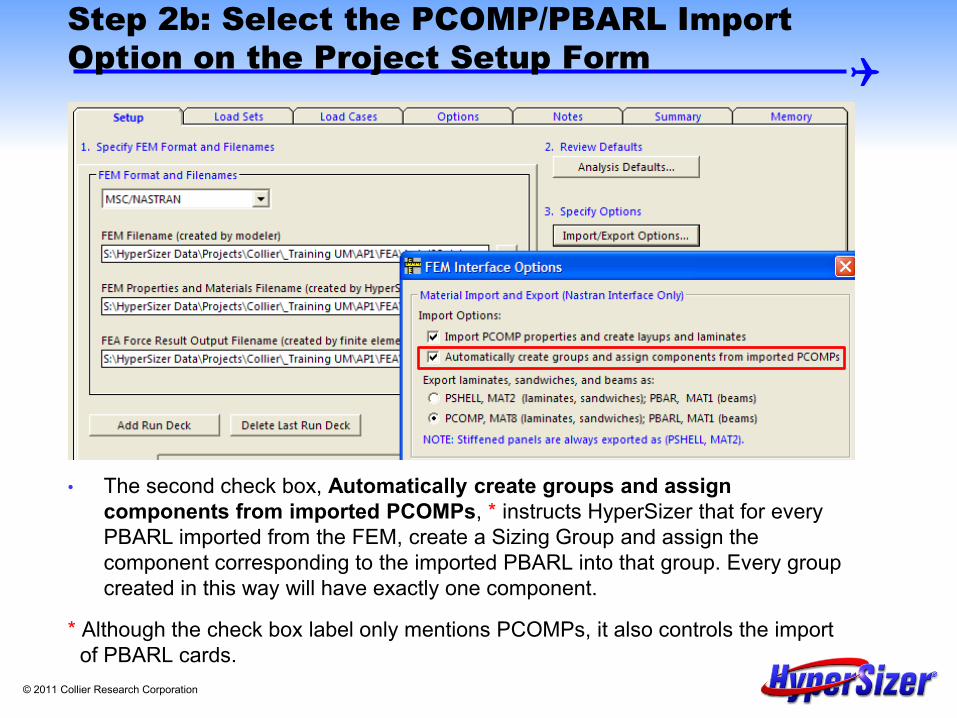
• The second check box, Automatically create groups and assign components from imported PCOMPs, * instructs HyperSizer that for every PBARL imported from the FEM, create a Sizing Group and assign the component corresponding to the imported PBARL into that group. Every group created in this way will have exactly one component.
* Although the check box label only mentions PCOMPs, it also controls the import of PBARL cards.

© 2011 Collier Research Corporation
Step 3: Import the FEM
• If materials are in the FEM that do not have corresponding materials in HyperSizer, the following message will be displayed.
• In this example, no material with ID = KMAT1%190 exists in the HyperSizer
database, therefore this message tells us that a material needs to be created to complete the definition of component 19.
• If this occurs, the error is not fatal, however these missing materials must be manually applied to the created components after import is completed.

© 2011 Collier Research Corporation
Step 4a: Open the Sizing form to analyze the components and obtain margins of safety A Group/Component will be created in HyperSizer with the following materials and dimensions: First, the “Web” variable will contain the isotropic material created in Step 1, KMAT1%180. The web thickness minimum and maximum values are set to 0.09" as spelled out in the PBARL card and the number of permutations is set to 1.
Blue Color = HyperSizer Isotropic Material
Web thickness of 0.09" as imported from the Nastran PBARL

© 2011 Collier Research Corporation
Step 4b: Open the Sizing form to analyze the components and obtain margins of safety
The Beam - Height variable will be filled out with the dimensions from the height dimension (DIM1) from the PBARL card. Note the minimum and maximum dimensions are both set to this dimension and the number of permutations is set to 1.
Beam Height of 6" as imported from the Nastran PBARL
The other dimensions of the beam component are set to those imported from the PBARL in the same way.

© 2011 Collier Research Corporation
Limitations
• Import of PBARL/MAT1 for group creation works only for beam concepts that are included in HyperSizer. For example, if the geometry type of the PBARL is “HEXA,” which is not a beam type in HyperSizer, this PBARL will not be imported.
• If the property in Nastran is defined with a PBAR instead of a PBARL, then no material, layup, or group will be created.
• MAT1 cards that are not used by PCOMP or PBARL cards will be ignored.

© 2011 Collier Research Corporation
ADVANCED EXAMPLE: MODELING A HYBRID METALLIC/COMPOSITE BONDED JOINT WITH HYPERSIZER AND FEA

© 2011 Collier Research Corporation
Problem Definition: Modeling a Bonded Joint in the Loads ‘Master’ FEM
The challenge is getting the proper stiffness and load path eccentricity (plate offsets) of a metallic/composite laminate bonded joint.
The following techniques apply to all adhesive joints or bonded doublers. This particular example is a clevis type joint in the NASA Crew Module. The
location is the intersecting ribs of the backbone known as the cruciform joint. The ribs are composite honeycomb sandwich.
There are two primary ways to model the joint with FEA. HyperSizer can quickly generate the data for both: 1) Single plane of shell elements to model entire sandwich panel 2) Two planes of shell elements to model facesheets and a solid
element to model sandwich core

© 2011 Collier Research Corporation
NASA Astronaut Crew Module, Composite Materials
Intersecting ribs

© 2011 Collier Research Corporation
The CCM “Loads” FEM
1) External aeroshell
2) Internal pressure shell
3) Backbone ribs are composite honeycomb sandwich.
4) Mesh size in area of interest. Single plane of elements for each rib. Each color is a different FEM property.

© 2011 Collier Research Corporation
Intersecting webs bonded to cruciform metal fitting
Green = Metal cruciform fitting
White = Sandwich core
Gray = Facesheet composite laminate
Problem Definition: Modeling a Bonded Joint in the Loads “Master” FEM

© 2011 Collier Research Corporation
Approach 1: Single Plane Modeling a Bonded Joint in the Loads “Master” FEM
Red Circle = grid Blue Line = edge of shell element The complete stack of core and the two facesheet bonds are modeled in the FEM as one plane of shell elements. No eccentricity is captured in this modeling approach due to load path fluctuations such as that caused by the plate offset of the facesheet and bonded metal fitting. However, HyperSizer will capture this effect and quantify the induced bending moments. So, with HyperSizer coupling, this is an efficient and accurate approach.

© 2011 Collier Research Corporation
Approach 1: Single Plane Modeling a Bonded Joint in the Loads “Master” FEM
A A A
A
E B C
D
B B
C C
D D
F F
Each letter represents a unique FEM property and a separate HyperSizer component. Property A captures the compliance (softness) of the internal metal box, which is important in getting the proper load path distribution computed with the global “loads” FEM. Three of the ribs are the same and share the same properties. One rib is thinner and has separate properties E and F. Properties B and E use a hybrid laminate to represent the bonded composite facesheet and metal joint, shown next.

© 2011 Collier Research Corporation
All Possible Material Selections and Dimensions are Available as HyperSizer Sizing Variables for the Bonded Joint
L2 L1
t3
t4
t2
t1
Facesheet Composite Laminate
Facesheet Composite Laminate
Metal Flange
Metal Flange
Sandwich Core
L3
t5
5 thickness variables 3 length variables 4 material variables (cruciform flange, adhesive, composite ply, and core) 1 variable for the layup 13 unique variables that can be optimized simultaneously

© 2011 Collier Research Corporation
The Composite/Metal Adhesively Bonded Joint is Modeled with one Nastran PCOMP
The 13 unique sizing variables for the clevis bonded joint can generate a wide spectrum of design alternatives.
The goal is to accurately and efficiently represent all of the possible design alternatives with a Nastran PCOMP.
The Nastran PCOMP can either be 1st defined in the FEM and then imported into HyperSizer 1st defined in HyperSizer and then exported to the FEM
In either case, the PCOMP is be modified by HyperSizer during sizing optimization and exported to the FEM for computing updated loads.

© 2011 Collier Research Corporation
As Fabricated and Tested Design Not to scale, Units = inch
0.6 0.1
0.081
0.896
0.080
Facesheet Composite Fabric IM7 4HS 3K 10 ply [45/0/45/0/45]s Layup
Facesheet Composite Fabric IM7 4HS 3K 10 ply [45/0/45/0/45]s Layup
Ti-6Al-4V Flange
Ti-6Al-4V Flange
Sandwich Aluminum Core, Hexcel 3/16-5052
0.5
0.02 0.020
The “loads” FEM has one property (Property B) to define the 1.2” cruciform length, therefore an average cruciform thickness of 0.065” is used. Since this data is not going into a stress model, but rather a loads model, it is accurate. HyperSizer will then account for the actual taper of the metal flange.
Note that the total height = 1.226” and distance from midplane to OML = 0.614” All of these thicknesses, composite layup, and materials go directly into the Nastran
PCOMP data, see next slide.
Adhesive = Paste Bond 9394
Midplane

© 2011 Collier Research Corporation
As Fabricated and Tested Design Nastran Imported and Exported PCOMP Data
$ Structural Component ID = 20013 material properties = TENSION MAT1* 30001 .162000000E+08 .620000000E+07 .306451613E+00 * .414078675E-03 .490000000E-05 .720000000E+02 .000000000E+00 MAT1* 30036 .610000000E+06 .230000000E+06 .326086957E+00 * .517598344E-04 .123000000E-04 .720000000E+02 .000000000E+00 MAT8* 59 .105300000E+08 .105300000E+08 .360000000E-01 * .760000000E+06 .760000000E+06 .760000000E+06 .146092133E-03 * -.100000000E-06 .150000000E-04 .720000000E+02 .947699900E+05 * .789750000E+05 .947699900E+05 .789750000E+05 .228000000E+05 MAT8* 510 .100000000E-03 .100000000E-03 .333330000E+00 * .100000000E-03 .680000000E+05 .300000000E+05 .658902692E-05 * .000000000E+00 .000000000E+00 .720000000E+02 * PCOMP 20013 -.6140 .220E+03 HOFF 72.0 + 30001 .0650 .000 30036 .0200 .000 + 59 .0081 45.000 59 .0081 .000 + 59 .0081 45.000 59 .0081 .000 + 59 .0081 45.000 59 .0081 45.000 + 59 .0081 .000 59 .0081 45.000 + 59 .0081 .000 59 .0081 45.000 + 510 .8960 .000 59 .0081 45.000 + 59 .0081 .000 59 .0081 45.000 + 59 .0081 .000 59 .0081 45.000 + 59 .0081 45.000 59 .0081 .000 + 59 .0081 45.000 59 .0081 .000 + 59 .0081 45.000 30036 .0200 .000 + 30001 .0650 .000 $
Ti 6Al-4V
Paste Adhesive
Gr/Ep IM7 Fabric
Sandwich Core
Nastran offset (Refer to beginning of PPT)

© 2011 Collier Research Corporation
After FEM Import, the Nastran PCOMP is Automatically Setup in HyperSizer

© 2011 Collier Research Corporation
Summary Comments
A “loads” FEM usually has only one property and few elements (in this case one property, B, and two elements) to define structural transitions. Such a model with the proper stiffness terms is capable of obtaining an accurate load path prediction.
This type of model is not refined enough to capture stresses properly. For the cruciform bonded clevis joint, an extremely high number of
elements is required to capture the stress intensity at the bonded flange tip. This is especially true for computing interlaminar shear and out-of-plane peel stresses.
HyperSizer is adept at calculating these stresses while coupling to the FEA-computed loads.
The next series of slides present an alternative approach for modeling the clevis joint with a loads FEM.

© 2011 Collier Research Corporation
Approach 2: Two Planes Modeling a Bonded Joint in the Loads “Master” FEM
Red circle = grid Blue line = edge of shell element Two planes of shell elements for the facesheets. Sandwich core modeled with solid elements.
Shell Elements Solid Elements
E
E F F

© 2011 Collier Research Corporation
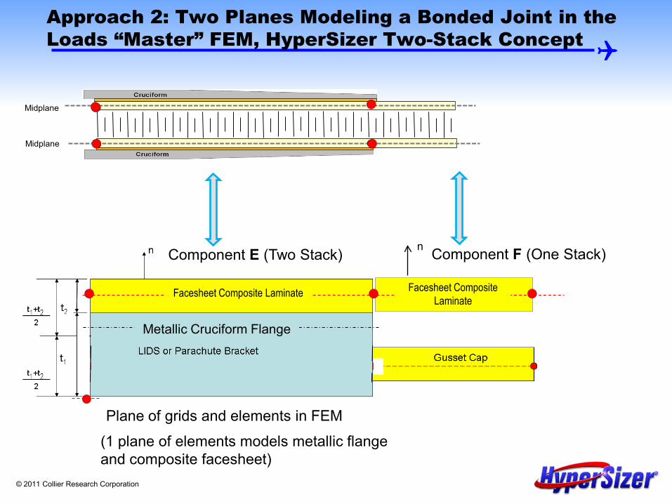
Approach 2: Two Planes Modeling a Bonded Joint in the Loads “Master” FEM, HyperSizer Two-Stack Concept
• This problem is represented with two HyperSizer components (illustrated on the next slide):
• Component E includes both the metallic flange and the composite facesheet laminate
• Component F includes only the composite facesheet laminate • In the FEM, Components E and F are both modeled using a single plane of
CQUAD finite elements. • In Component E, the metallic flange and the composite facesheet laminate
are sized, • with independent variables but simultaneously in HyperSizer using the
“Two-Stack” concept • this permits user flexibility in sizing the metal with a continuous
thickness variable and the laminate as a discrete variable
© 2011 Collier Research Corporation
(1 plane of elements models metallic flange and composite facesheet)
Component E (Two Stack) Component F (One Stack)
Gusset Cap
n
Approach 2: Two Planes Modeling a Bonded Joint in the Loads “Master” FEM, HyperSizer Two-Stack Concept
Metallic Cruciform Flange
Facesheet Composite Laminate Facesheet Composite Laminate
Plane of grids and elements in FEM
Midplane
Midplane

© 2011 Collier Research Corporation
The HyperSizer Two-Stack Concept
• The Two-Stack concept is activated on the Concepts tab of the Sizing form. • Specify materials and dimensions for “Stack 1” and “Stack 2” on the
Variables tab. Stack 2 = 0.065” metal flange and not the core.

© 2011 Collier Research Corporation
t1/2
t2+t1/2
(t2+t1)/2
(t2+t1)/2
t1+t2/2
t2/2
Two Stack – Three Choices for Reference Plane on the Options tab of the Sizing form
Two-Stack One-Stack
Two-Stack One-Stack
Two-Stack One-Stack
Option 1
Option 2
Option 3
The two-stack representing the composite facesheet and metal flange can be represented three ways. Option 1 is the desired modeling for this example. Options 2 or 3 will give incorrect loads when passed to the FEM. Correct
Choice
Incorrect Choice
Incorrect Choice

© 2011 Collier Research Corporation
Conclusions
• HyperSizer can correctly model many different structural configurations using One-Stack, Two-Stack, or Sandwich options.
• The choice of reference plane is key, both in HyperSizer and the FEM, to ensure modeling of the correct physical problem.
• Both on FEM import and export, HyperSizer tracks the correct reference plane on the PCOMP cards so that the HyperSizer and FEA solutions are consistent.