Embed Size (px)
Citation preview

Selection of an Agency for Redevelopment of Kanera Dev Feeder Canal Under Smart City Mission
1 | P a g e
Sagar Smart City Limited
Request for Proposal - Volume 2
For
Selection of an Agency for Redevelopment of Kanera Dev
Feeder Canal Under Smart City Mission
Sagar Smart City Limited,
Sagar Smart City Office
2nd Floor, ICCC Building,
New Collectorate Premises,
Sagar, Madhya Pradesh-470002
Phone: 07582-242850
Email: [email protected]

Selection of an Agency for Redevelopment of Kanera Dev Feeder Canal Under Smart City Mission
2 | P a g e
1. Technical Secifications for Civil Works
1.1 CIVIL WORKS AS PER MORTH
As per MORTH Specification 2013
S.No. Work IS Code/ Guideline to be referred (MORTH)
1 EMBANKMENT AND SUBGRADE
CONSTRUCTION
Density requirement Table 300-1
IS:2720(Part VIII)
Control test on Borrow material IS: 2720 (Part II, IV, V, IIX, XVI, XXIV)
2 CRUSHER RUN MACADAM
Aggregate Grading requirement Table 400-12
Physical requirement of Course Aggregate Table 400-13
IS:2386 (Part I, III, IV)
IS:2720 (Part V)
3 DRY LEAN CEMENT CONCRETE
Cement Table 600 IS:269, IS 455, IS 1489
Aggregate Gradation Table 600-1
4 CEMENT CONCRETE PAVEMENT SP:62.2014, IRC -58
Cement IS:269, IS:8112, IS:12269 IS:SP:23
Admixture IS:6925, IS:9103
Aggregate IS:383
Dowel bar & Tie bar IS:432 IS:1139 IS:1786
Concrete Mix Proportioning IS:10262:2009
5 Road traffic Signal IRC:93 IS:7537
1.2 EMBANKMENT AND SUB GRADE CONSTRUCTION
Materials for use in Embankment shall not contain particles larger than 75mm.However in the 500mm below
sub-grade top level in both embankments and cuttings shall not contain particles larger than 50mm.
In-situ materials in the 500mm below sub-grade top level in cutting that does not meet these requirements,
shall either be spoiled or if suitable, placed in the embankment and replaced with material from cutting or
borrow pits that do meet the requirements for use in the 500mm below sub-grade top level.
The Contractor shall ensure that earthworks (Embankment / sub-grade) proceed towards completion in
orderly and continuous manner. The Contractor shall submit a written request for approval of any layer at

Selection of an Agency for Redevelopment of Kanera Dev Feeder Canal Under Smart City Mission
3 | P a g e
least 3 working days in advance before he intends to cover a completed layer. Fill material for subsequent
layer shall be placed immediately after approval of the previous layer to ensure retention of moisture.
TABLE 300-1. DENSITY REQUIREMENTS OF EMBANKMENT AND SUBGRADE MATERIALS
S.No. Types of Work Maximum laboratory dry unit weight when
tested as per IS: 2720 (Part 8)
1 Embankments up to 3 metres height, not
subjected to extensive flooding
Not less than,15.2 kN/cu.m.
2 Embankments exceeding 3 metres height or
embankments of any height subject to long
periods of inundation
Not less than 16.0 kN/cu. m.
3 Subgrade and earthen shoulders /
verges/backfill
Not less than 17.5 kN/cu. m.
Notes: (1) This Table is not applicable for lightweight fill material e.g. cinder, fly ash etc. (2) The Engineer
may relax these requirements at his discretion taking into account the availability of materials for construction
and other relevant factors. (3) The material to be used in subgrade should also satisfy design CBR at the
dry unit weight applicable as per Table 300-1
The moisture content of fill material shall be adjusted immediately prior to the compaction by either uniformly
mixing water or drying out the materials so that the moisture content during compaction shall be in
accordance with the Optimum Moisture Content determined in the laboratory.
Each layer shall be compacted at the Optimum Moisture Content to a dry density equal to the percentage of
Maximum Dry Density (MDD) Specified below (AS PER MORTH Table No.-3.02):
All fill materials in embankment 95% of MDD (Modified Proctor Density)
Materials in 500mm. below sub-
Grade
97% of MDD (Modified Proctor top level in embankment:
Density)
Materials in 500mm. below sub-: 97% of MDD (Modified Proctor grade top level in cutting and
shoulder Density)
Compaction of embankment layers, and the layers, 500mm. below the sub grade top level, shall be
completed to the procedures proposed by the Contractor in accordance with the clauses of Specification.
The materials, 500mm. below sub grade top level in both fill areas and in cuttings, shall be completed in
three compacted layers.
The specification shall apply to the construction of embankment including Sub-grade and earthen shoulders
with approved materials obtained from roadway and drain Excavation or borrow pits. All embankments shall
be constructed as per specification and as per drawings.
CONTROL TEST ON BORROW MATERIALS:
• Sand content - Two test per 3000m3 (as per IS-2720 Part iv).
• Plasticity - Two test for each type of soil (as per IS-2720 Part-v)
• Proctor Test - Two test of each type of soil (as per IS-2720 Part-iix)
• Deleterious content- As Required (as per IS-2720 Part xxiiv)
• Natural moisture content - Two test of each type of soil (as per IS-2720 Part-ii)
• Field density test:
• For embankment- One test for 1000m2 of compacted area (Minimum 6nos. in a set)
• For sub-grade- One Set of two test for 500m2 of compacted

Selection of an Agency for Redevelopment of Kanera Dev Feeder Canal Under Smart City Mission
4 | P a g e
• Area (Minimum 6 no. in a set)
• CBR Test - One test per for each kind of soil or closer & when
required by the engineer (as per IS-2720 Part xvi (for sub- grade only)
Sand Replacement method as approved by Engineer shall be used at site.
1.3 CRUSHER RUN MACADAM
The material to be used for the work shall be crushed rock. If crushed gravel/shingle is used, not less than
90 per cent by weight of the gravel/shingle pieces retained on 4,75 mm sieve shall have at least two fractured
faces. It shall be free from any organic mailer and other deleterious substances and shall be of such nature
that it can be compacted readily under watering and Stances and shall be such nature that it can be
compacted readily under watering and rolling to form a firm, stable base. The aggregate shall conform to the
grading and quality requirement shown in Tables 400-12 and 400-13. At the option of the contractor, the
grading for either 53 mm maximum size or 37.5 mm maximum size shall be used, except that once a grading
is selected, it shall not be changed without the Engineer’s approval.
TABLE 400.12. AGGREGATE GRADING REQUIREMENTS
Sieve size Per cent passing by weight
53 mm max. size 37.5 mm max. size
63mm 100mm
45mm 87-100 100
22.4mm 50-85 90-100
5.6mm 25-45 35-55
710micron 10-25 10-30
90micron 2-9 2-9
TABLE 400-13. PHYSICAL REQUIREMENTS OF COARSE AGGREGATES FOR CRUSHER-RUN
MACADAM BASE
S.No. Test Test Method Requirements
1 *Los Angeles Abrasion value or *
Aggregate Impact value
IS: 2386 (Part - 4)
IS: 2386 (Part- 4) or IS:
5640
40 Maximum
30 Maximum
2 Combined Flakiness and Elongation
Indices (Total)
IS: 2386 (Part-1) 30maximum
3 Water absorption IS: 2386 (Part-3) 2 per cent Maximum
4 ** Liquid Limit of material passing 425
microns
IS: 2720 (Part-5) Not more than25

Selection of an Agency for Redevelopment of Kanera Dev Feeder Canal Under Smart City Mission
5 | P a g e
5 Plasticity Index of material passing 425
microns
IS: 2720 (Part-5) Not more than 6
* Aggregate may satisfy requirements of either of the two tests. *
* If the water absorption is more than 2 per cent, soundness test shall be carried out as per IS:2386(Part -
5).
1.4 DRY LEAN CEMENT CONCRETE-
Cement: Any of the following types of cement may be used with prior approval of the Engineer:
• Ordinary Portland Cement IS: 269
• Portland Slag Cement IS: 455
• Portland Pozzolana Cement IS: 1489
If the subgrade is found to consist of soluble sulphates in a concentration more than 0.5 per cent, cement
used shall be sulphate resistant and shall conform to IS: 6909, Cement to be used may preferably be
obtained in bulk form. It shall be stored in accordance with stipulations contained in Clause 1014 and shall
be subjected to acceptance test prior to its immediate use.
Aggregates:
Aggregates for lean concrete shall be natural material complying with IS: 383. The aggregates shall not be
alkali reactive. The limits of deleterious materials shall not exceed the requirements set out in IS: 383. In
case the Engineer considers that the aggregates are not free from din, the same may be washed and drained
for at least 72 hours before batching, as directed by the Engineer.
Coarse aggregate:
Coarse aggregate shall consist of clean, hard, strong, dense, non-porous and durable pieces of crushed
stone or crushed gravel and shall be devoid of pieces of disintegrated stone, soft, flaky, elongated, very
angular or splintery pieces. The maximum size of the coarse aggregate shall he 25 mm. The coarse
aggregate shall comply with Clause 602.2.4.2.
Fine aggregate:
The fine aggregate shall consist of clean, natural sand or crushed stone sand or a combination of the two
and shall conform to IS: 383. Fine aggregate shall be free from soft particles, clay, shale, loam, cemented
particles, mica, organic and other foreign matter. The fine aggregate shall comply with Clause 602.2.4.3.
The coarse and fine aggregates may be obtained in either of the following manner: (i) In separate nominal
sizes of course and fine aggregates and mixed together intimately before use. (ii) Separately as 25 mm
nominal single size, 12.5 mm nominal size graded aggregates - and Tine aggregate of crushed stone dust
or sand or a combination of these two. The material after blending shall conform to the grading as indicated
in Table 600-1.
TABLE 600-1. AGGREGATE GRADATION FOR DRY LEAN CONCRETE
Sieve Designation Percentage passing the sieve by weight
26.50 mm 100
19 mm 80-100
9.50 mm 55-75
4.75 mm 35-60
600 microns 10-35
75 microns 0-8

Selection of an Agency for Redevelopment of Kanera Dev Feeder Canal Under Smart City Mission
6 | P a g e
1.5 CEMENT CONCRETE PAVEMENT
Cement
Any of the following types of cement capable of achieving the design strength may be used with prior
approval of the Engineer, but the preference should be to use at least the 43 Grade or higher.
• Ordinary Portland Cement, 33 Grade. IS: 269
• Ordinary Portland Cement, 43 Grade IS: 8112,
• Ordinary Portland Cement, 53 Grade, IS: 12269.
If the soil around has soluble salts like sulphates in excess of 0.5 per cent, the cement used shall be sulphate
resistant and shall conform to IS: 12330. Guidance may be taken from IS: SP: 23
Admixtures: Admixtures conforming to IS:6925 and IS: 9103 shall be permitted to improve workability of the
concrete or extension of setting time, on satisfactory evidence that they will not have any adverse effect on
the properties of concrete with respect to strength, volume change, durability and have no deleterious effect
on steel bars. The particulars of the admixture and the quantity to be used, must be furnished to the Engineer
in advance to obtain his approval before use.
Aggregates
Aggregates for pavement concrete shall be natural material complying with IS: 383 but with a Los Angeles
Abrasion Test result not more than 35 per cent the limits of deleterious materials shall not exceed the
requirements set out in IS: 383. The aggregates shall be free from chert, flint, chalcedony or other silica in a
form that can react with the alkalies in the cement. In addition, the total chlorides content expressed as
chloride ion content shall not exceed 0.06 per cent by weight and the total sulphate content expressed as
sulphuric anhydride (S03) shall not exceed 0.25 per cent by weight.
Coarse aggregate
Coarse aggregate shall consist of clean, hard, strong, dense, non-porous and durable pieces of crushed
stone or crushed gravel and shall be devoid of pieces of disintegrated stone, soft, flaky, elongated, very
angular or splintery pieces. The maximum size of coarse aggregate shall not exceed 25 mm for pavement
concrete.
Fine aggregate
The fine aggregate shall consist of clean natural sand or crushed stone sand or a combination of the two
and shall conform to IS:383. Fine aggregate shall be free from soft particles, clay, shale, loam, cemented
particles, mica and organic and other foreign matter. The fine aggregate shall not contain deleterious
substances more than the following:
• Clay lumps 4.0 per cent
• Coal and lignite 10 per cent
• Material pissing IS Sieve No. 75 micron 4.0 per cent
Water
Water used for mixing and curing of concrete shall be clean and free from injurious amount of oil, sail, acid,
vegetable matter or other substances harmful to the finished concrete. It shall meet the requirements
stipulated in IS: 456.
Mild steel bars for dowels and tie bars
These shall conform to the requirements of IS: 432, IS: 1139 and IS: 1786 as relevant. The dowel bars shall
conform to Grade S 240 and tie bars to Grade S 415 of I.S.
Longitudinal joint
The longitudinal joints shall be saw cut as per details of the joints shown in the drawing. The groove may be
cut after the final set of the concrete. Joints should be sawn to at least 1/3 the depth of the slab ± 5 mm as
indicated in the drawing.
Selection of an Agency for Redevelopment of Kanera Dev Feeder Canal Under Smart City Mission
7 | P a g e
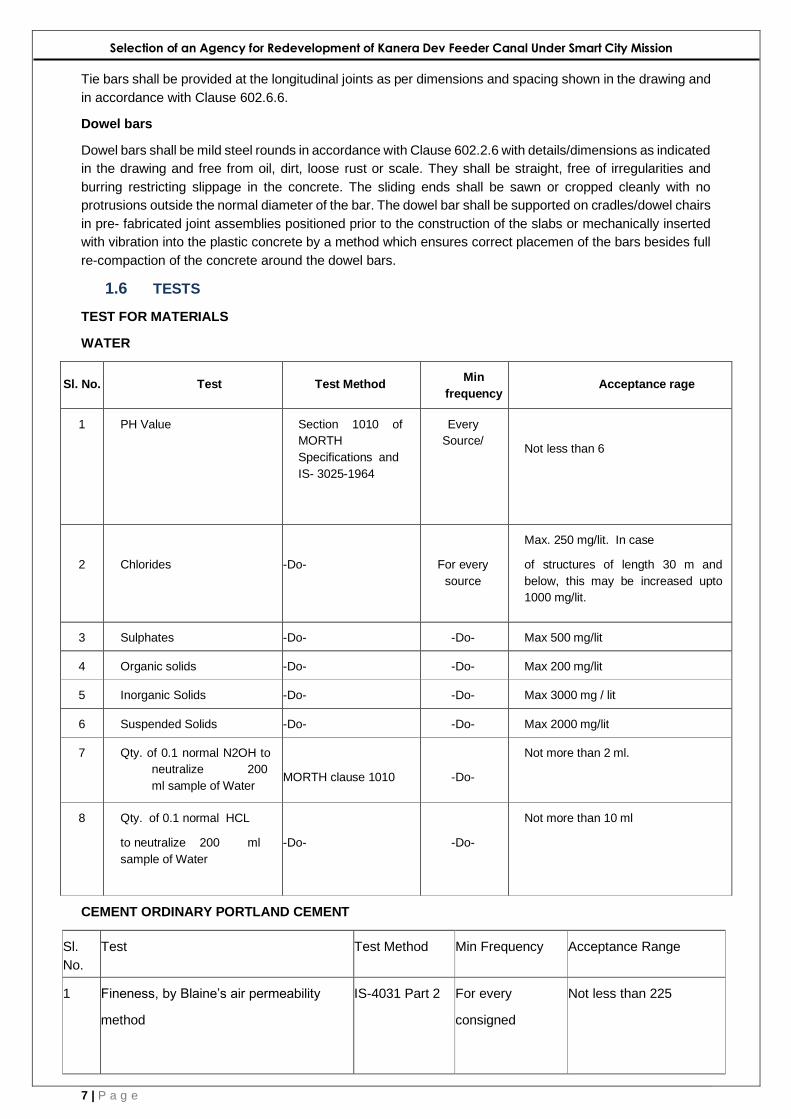
Tie bars shall be provided at the longitudinal joints as per dimensions and spacing shown in the drawing and
in accordance with Clause 602.6.6.
Dowel bars
Dowel bars shall be mild steel rounds in accordance with Clause 602.2.6 with details/dimensions as indicated
in the drawing and free from oil, dirt, loose rust or scale. They shall be straight, free of irregularities and
burring restricting slippage in the concrete. The sliding ends shall be sawn or cropped cleanly with no
protrusions outside the normal diameter of the bar. The dowel bar shall be supported on cradles/dowel chairs
in pre- fabricated joint assemblies positioned prior to the construction of the slabs or mechanically inserted
with vibration into the plastic concrete by a method which ensures correct placemen of the bars besides full
re-compaction of the concrete around the dowel bars.
1.6 TESTS
TEST FOR MATERIALS
WATER
Sl. No. Test Test Method Min
frequency Acceptance rage
1 PH Value Section 1010 of
MORTH
Specifications and
IS- 3025-1964
Every
Source/
Not less than 6
2
Chlorides
-Do-
For every
source
Max. 250 mg/lit. In case
of structures of length 30 m and
below, this may be increased upto
1000 mg/lit.
3 Sulphates -Do- -Do- Max 500 mg/lit
4 Organic solids -Do- -Do- Max 200 mg/lit
5 Inorganic Solids -Do- -Do- Max 3000 mg / lit
6 Suspended Solids -Do- -Do- Max 2000 mg/lit
7 Qty. of 0.1 normal N2OH to
neutralize 200
ml sample of Water
MORTH clause 1010
-Do-
Not more than 2 ml.
8 Qty. of 0.1 normal HCL
to neutralize 200 ml
sample of Water
-Do-
-Do-
Not more than 10 ml
CEMENT ORDINARY PORTLAND CEMENT
Sl.
No.
Test Test Method Min Frequency Acceptance Range
1 Fineness, by Blaine’s air permeability
method
IS-4031 Part 2 For every
consigned
Not less than 225
Selection of an Agency for Redevelopment of Kanera Dev Feeder Canal Under Smart City Mission
8 | P a g e
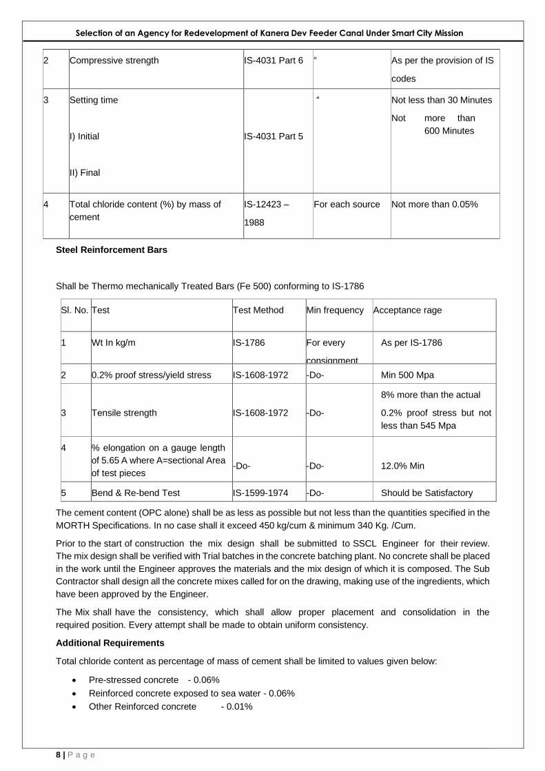
2 Compressive strength IS-4031 Part 6 “ As per the provision of IS
codes
3 Setting time
I) Initial
II) Final
IS-4031 Part 5
“ Not less than 30 Minutes
Not more than
600 Minutes
4 Total chloride content (%) by mass of
cement
i
IS-12423 –
1988
For each source Not more than 0.05%
Steel Reinforcement Bars
Shall be Thermo mechanically Treated Bars (Fe 500) conforming to IS-1786
Sl. No. Test Test Method Min frequency Acceptance rage
1 Wt In kg/m IS-1786 For every
consignment
As per IS-1786
2 0.2% proof stress/yield stress IS-1608-1972 -Do- Min 500 Mpa
3
Tensile strength
IS-1608-1972
-Do-
8% more than the actual
0.2% proof stress but not
less than 545 Mpa
4 % elongation on a gauge length
of 5.65 A where A=sectional Area
of test pieces
-Do-
-Do-
12.0% Min
5 Bend & Re-bend Test IS-1599-1974 -Do- Should be Satisfactory
The cement content (OPC alone) shall be as less as possible but not less than the quantities specified in the
MORTH Specifications. In no case shall it exceed 450 kg/cum & minimum 340 Kg. /Cum.
Prior to the start of construction the mix design shall be submitted to SSCL Engineer for their review.
The mix design shall be verified with Trial batches in the concrete batching plant. No concrete shall be placed
in the work until the Engineer approves the materials and the mix design of which it is composed. The Sub
Contractor shall design all the concrete mixes called for on the drawing, making use of the ingredients, which
have been approved by the Engineer.
The Mix shall have the consistency, which shall allow proper placement and consolidation in the
required position. Every attempt shall be made to obtain uniform consistency.
Additional Requirements
Total chloride content as percentage of mass of cement shall be limited to values given below:
• Pre-stressed concrete - 0.06%
• Reinforced concrete exposed to sea water - 0.06%
• Other Reinforced concrete - 0.01%

Selection of an Agency for Redevelopment of Kanera Dev Feeder Canal Under Smart City Mission
9 | P a g e
The total sulphuric anhydride (SO3) content in the concrete is to be limited to 4% of cement. Use of
admixtures in concrete may be required under the contract to promote special properties in the finished
concrete or may be proposed by the Contractor to assist him in compliance with the Specification.
The maximum size of coarse Aggregate for concrete to be used in various components shall be as per Table
no. 1700-7 of MORTH Specifications.
When it is necessary to deposit concrete under water concrete it shall contain 10% more cement than that
required for the same mix placed in the dry. Concrete shall not be placed in water having temperature below
5 0C. All under water concreting shall be carried out by tremie method only. The temperature of concrete,
when deposited shall not be less than 16 degree Celsius or not more than 33 0C. Concrete shall be protected
during the first stage of hardening from loss of moisture and from the development of temperature differential
within the concrete sufficient to cause cracking.
The methods used for curing shall not cause damage of any kind to the concrete. Curing shall be
continued for as long as may be necessary to achieve the above objectives but in any case for at least 14
days or until the concrete is covered by later construction whichever is the shorter period.
The curing process shall commence as soon as the concrete is hard enough to resist damage from the
process, and in the case of large area or continuous pours, shall commence on the completed section of the
pour before the rest of the pour is finished.
Water used for curing shall be of the same quality as that used for mixing. Curing compound shall become
stable and impervious to the evaporation of water from the concrete surface within 60 minutes of application.
The material shall not react chemically with the concrete and shall not crack, peel or disintegrate within 3
weeks after the application.
Immediately after removing the forms, exposed bars shall be cut to a depth of at least 50 mm below the
surface of concrete and the resulting holes shall be filled with cement mortar. All fins caused by form joints,
all cavities, honeycomb spots, broken edges etc. shall be thoroughly cleaned and rectified by mortar of
cement and fine aggregates. All construction and expansion joints in the concrete work shall be tooled and
free from any mortar or concrete.

Selection of an Agency for Redevelopment of Kanera Dev Feeder Canal Under Smart City Mission
10 | P a g e
1.7 CONCRETE: QUALITY OF WORK
Check Method Frequency Accepted range
I. Prior to concreting
1. Mix design
2. Weigh batching
3. Line & level
4. Formwork
5. Placing of reinforcement
6. Plant & Equipment
7. Adequate man power
8. Curing Arrangement
9. Walk-way for inspection
10. Safety arrangement
11. Lighting, if night work
For every change of
source
For every concreting
operation
To conform to the
respective
specifications
To be Satisfactory
II. Batching and pouring of concrete
1. Mixing
2. Transportation, placing and
compacting of Concrete
3. Construction of Joint
4. Collection of Test cubes
-Do-
-Do-

Selection of an Agency for Redevelopment of Kanera Dev Feeder Canal Under Smart City Mission
11 | P a g e
III. Post – Concreting
1. Curing
2. Stripping side shutters
3. Stripping soffit shutters
4. Removal of props
-Do-
-Do-
IV. Quality of workmanship (Clause 1700 OF
MORTH specification)
-Do-
Sl. No. Check Method Frequency Acceptance Range
1 Min Strength of concrete IS-512 For every
concrete
Operation
As per approved design and drawing
2 Minimum cement content and
Max. w/c ratio
-Do-
-Do-
3. Maximum Cement Content -Do- 450 kg/cum( OPC)
4 Consistency by slump test IS-516
-Do-
Type of Structure Slump in
mm
RCC with widely spaced
reinforcement
RCC with fairly spaced
reinforcement
RCC & PSC with highly
congested reinforcement.
Underwater concreting throu
tremie e.g. button plug, cast
situ pilling
40-50
50-75
75-125 g
100-
200
5 Compressive strength
of
working cubes (28 days)
As per
Table 1700-
9 of
MORTH
-
2013
1) Mean strength determined from any
group of 3 consecutive samples should
exceed the specified characteristic
strength
Selection of an Agency for Redevelopment of Kanera Dev Feeder Canal Under Smart City Mission
12 | P a g e
2) Strength of any sample is not less
than specified characteristic strength
minus 3.5 MPa
FREQUENCY
Quantity of Concrete in m3 No. of Samples
1-5 1
6-15 2
16 – 30 3
31-50 4
51 & above 4 plus one addl. For each addl. 50 m3 or part
Thereof
1.8 MORTAR
Mortar shall be composed of fine aggregate and ordinary Portland cement. The mix proportions shall be as
stated on the drawings or elsewhere in the specification.
The mixing shall be done in a mechanical mixer. Hand mixing can be restored to as long as uniform density
of mix and its strength are assured subject to prior approval of the Engineer. Mortar shall be mixed only in
such quantity as required for immediate use.
Check List
1) Working benchmarks shall be established with reference to B.M. given by the Client
2) Levels of working B.M. to be got approved by the Client
3) Survey instruments
i. Leveling Instruments: Precision automatic levels having standard deviation of 5
Mm/km.
ii. Measurement of Angle: Total Station having an accuracy of Two Second iii. Measurement of
distance: Distomate (Electronic distance meter)
4) A proper record of all benchmarks, survey control points and setting out points with suitable
supporting sketches should be maintained.
1.9 SUB STRUCTURE
Sl. No. Test Specification Frequency Specified
Value
1 Material Most specification-2013
Section 1000
As specified
2 Form Work Section 1500 of
MORTH Specification-2013
For each member

Selection of an Agency for Redevelopment of Kanera Dev Feeder Canal Under Smart City Mission
13 | P a g e
3 Concreting As per specification For each concreting
4 Tolerance in
Concrete elements
Clause 2208 of
MORTH specification
Each Member
Variation in c/s dimensions + 10 mm, - 5 mm
Misplacement from specified position in plan 10 mm
Variation of level at Top + 10 mm
Variation of R.L. of bearing Area + 5 mm
Variation from plumb over full height + 10 mm
Surface irregularities measured with 3m straight
edge
All surfaces except bearing areas
Bearing area
5 mm
1.10 Super Structure
Sl. No. Test Specification Frequency Specified
Value
1 Materials To conform to section
1000 of MORTH Specification test
as indicated in the manual
As indicated As indicated
2 Dimensions line and
level
As approved Drawing Each Member As per
approved
drawing
3 Form Work Section 1500 of MORTH
specification
Each Member
4 Steel reinforcement Section 1600 of MORTH
Specification
-Do-
5 Structural Conc. Section 1700 of MORTH
specification
-Do-
6 Prestressing Section 1800 of MORTH
specification
-Do-
7 Quality and
workmanship
Section 2300 of MORTH
specification
-Do-
Selection of an Agency for Redevelopment of Kanera Dev Feeder Canal Under Smart City Mission
14 | P a g e
8 Tolerance for cast-in-
situ super-structure
Cl2306.2 of MORTH specification -Do-
TOLERANCE IN VARIATIONS
1 Thickness of top and bottom slab for box girder and
bottom flange for T girder or slab
- 5 mm to + 10mm
2 Web Thickness - 5 mm to + 10 mm
3 Overall width or depth + 5 mm
4 Length overall and length between bearing Not more than + 10mm or +
0.1% of span which ever is lesser
5 Surface irregularities on 3m straight edge 5 mm

Selection of an Agency for Redevelopment of Kanera Dev Feeder Canal Under Smart City Mission
15 | P a g e
1.11 FILTER MEDIA, BACKFILLING BEHIND ABUTMENT & WING WALL
This item of work deals with activities of Filter media, Backfilling behind Abutments and Wing Wall with
approved materials as per the terms of contract conditions, approved Drawings. This item of work shall
confirm to the clause 2504.2.2, 305 & 309.3.2 and IRC – 78 of the Technical specifications.
Filter Media is proposed from the tests conducted in the laboratory and checked for its suitability as per
Clause 2504.2.2 of MORTH Specification.
Back filling will be done with the material from approved borrow areas.
Procedure
a) Initially filter media is laid with coarse filter towards weep hole of Abutment and finer material towards
earthen side layer by layer as per the technical requirement.
b) After completion of each filter media layer to the required suitable height back filling will be done
simultaneously in layers matching the height with the filter media layer till it reaches the existing ground
level behind Abutment and compacted as per requirement.
c) Embankment construction will also be taken up either separately or simultaneously along with filter media
and back filling layers.
1.12 Stone Pitching
This work consists of covering the slopes of road embankments with stones over a layer of granular material
(Filter).
As per approved drawings and MORTH Specifications.
The stone will be sound, hard, durable and fairly regular in shape. Quarry stone would be used. The round
boulders and the stones subjected to the marked deterioration by water or weather will not be accepted. The
material for filter will be sand, gravel, stone or coarse sand and it will prevent escape of the embankment
material through the voids of the stone pitching and as well as to allow free movement of water without
creating any uplift head on the pitching.
1.13 Earthwork Excavation on and above mud
Excavation in different types of soil in canal bed and sides slopes for lining, sleepers, steps, coping and
under- drainage-arrangement including dressing to the profile and disposal of excavated materials etc.
Complete In all kind of soft/loose/hard/dense soils, morrum & morrum mixed with boulders and mud
The work includes necessary excavation and back filling of the material resulting from uprooting of trees nd
stumps to required compaction, handling and dsposal of cleared materials.
Pipeline, sewer, cable, shall be protected from damage & it shall be repaired by the contractor at his
own cost.
The loading and lifting of the material / excavated earth will be applicable based on the Schedule of
Rates as and when required.
In this excavation work includes the excavation of the existing soils in the bed of the canal and the
sides for maintaining slopes and including all the dressing work and disposal of the materials.
The mentioned worked can be executed on the all kind of soil available on site like soft soil, loose
soil, hard soil, dense soil and other hard material like boulder and mud also.
The limits of excavation shall be set out true to lines, curves, slopes, grades and sections as shown
in the drawings.
All the material involves in excavation shall classified below:

Selection of an Agency for Redevelopment of Kanera Dev Feeder Canal Under Smart City Mission
16 | P a g e
Soil: This item shall comprise top soil, sand silt, loam, clay, mud, loose morum, a mixture of these
and similar material which yields to the ordinary digging implement. This item shall include soil like
soft clays excavated below the original ground level and swamps and soils excavated from other
areas requiring continuous pumping or bailing out of water.
1.14 Dewatering
Dewatering and pumping the working area including all connecting operation required etc. complete.
for cleanliness of working area by 5hp to 10 hp diesel pump
As the existing canal is in watering in condition, dewatering is required for obtaining clear and specific
measurements. It is also required when water is encountered in the lining area, suitable dewatering
system is required for further progress. Where suction pumps are used it is desirable that the suction
hose be 20 mm larger in diameter than the discharge opening on the pump and the section head
not more than 4.5m. This requires resetting the pump on a frame attached to cribbing at the intervals
of about 3.5m.
Formwork or coffer shall be sufficiently tight to ensure still water if practicable, and in any case to
reduce the flow of water to less than 3 m per minute through the space into which the concrete is to
be deposited of forms in still water shall be sufficiently tight to prevent loss of mortar through the
walls. Dewatering by pumping shall not be done while concrete in being placed until 24 hours
thereafter.
1.15 Dry Rubble wall (Toe Wall) Providing and constructing Dry rubble wall (toe wall) with stone of minimum size 0.021 cum at the
base of stone pitching or rip-rap excluding excavation etc. complete.
From the cross sectional area of the embankment, the area occupied by seepage drain, boulder toe,
pitching, filters, sluice barrel and parapet walls embedded in the earthwork or any other opening
having area 0.1 sqm shall be deducted .
No deduction is admissible from the sectional measurements for voids of seepage drain, boulder
toe, pitching and filters.
Stone size should be of minimum 0.021 Cum at the base of stone pitching.
1.16 Filter Blanket
Providing filter blanket horizontally, Including laying, spreading, packing etc. Complete in layers of
required thickness but excluding excavation of foundation. Aggregate 40 mm nominal size.
Where indicated in the drawings, filter blankets shall be laid under the downstream portion of the
embankment. The number of layer in the filter blanket or seepage drains and thickness of such layer
shall be specified in the drawing. Filter shall be placed and tamped into place in such a manner that
mixing of filter with foundation or backfill materials will not occur.
The filter material shall consist of clean, sound and well grained aggregate. The material shall be
free from debris, wood, vegetable matter, decomposed rock and other deleterious matter. The
gradation of each filter layer shall meet the following requirements with respect to the material to be
protected and also with respect to the adjacent filter layers.
D - 15 of the filter / D - 15 of the base material = > 4 and < 20
Provided the filter does not contain more than 5 percent of material finer than 0.07 mm (No. 200
sieve)

Selection of an Agency for Redevelopment of Kanera Dev Feeder Canal Under Smart City Mission
17 | P a g e
D - 15 of the filter / D - 85 of the base material = < 5
D - 50 of the filter / D - 50 of base material = < 25
The grain size curve of the filter shall be roughly parallel to that of the base material. In the above,
D-15 is the size at which 15 percent of total soil particles are smaller, the percentage being by weight
as determined by mechanical analysis. The D.- 85 size is that at which 85 percent of the total soil
particles are smaller. It shall be laid in single layer or in layers as per the drawing if more than one
filter layer is required, the same criteria shall be allowed. The finer filter is considered as the base
material for selection of the gradation of the coarser filter.
(v) In order to prevent segregation and bridging of large particles, (the maximum) particle size shall
not exceed 75 mm. The requirement for grading of the filter shall be established by the field
laboratory based on mechanical analysis of adjacent materials. The material brought to the site shall
be subjected to the aforesaid tests in the laboratories at the project site. The result shall be final and
binding and all material not conforming to the requirement so determined shall not be permitted, for
use on the said works. (vi) The following gradation is tentatively suggested but is subject to
modifications after further laboratory tests: -
(a) For filter material in contact with foundation or earth fill material Well graded coarse sand & gravel
passing 12 mm screen
(b) For middle layer of filter blanket & for layers in contact with rock fill Coarse gravel passing 75 mm
screen and retained on 12 mm screen
1.17 Providing Non-swelling soils below lining of Canal
Providing and placing approved cohesive non- swelling soils, below lining in canal bed and side
slopes including serration in soil, breaking of clods, laying in layers of 15 cm. thickness, cutting and
finishing in required bed grade & side slopes including dressing, watering, compaction (at optimum
moisture content to obtained dry density not below 90%) etc. Complete.
1. Tamping in Canal bed
Tamping in canal bed and sides including saturation up to 30 cm depth for preparation of earthen
sub-grade before laying in-situ cement concrete lining.
At least one tamping shall be provided for each area of the bed surface. The space measured on
the surface of the canal between the centers of two adjacent tamping shall not be less than 230 mm.
The cross-sectional area of each tamping foot shall not be less than 65 sqcm at a plane normal to
the axis.
Much of the tamping should be directed at a slight angle and towards the sides of the holds to assure
maximum compaction in these areas.
2. Embankment and sub grade construction
Materials for use in Embankment shall not contain particles larger than 75mm.However in the
500mm below sub-grade top level in both embankments and cuttings shall not contain particles
larger than 50mm.
In-situ materials in the 500mm below sub-grade top level in cutting that does not meet these
requirements, shall either be spoiled or if suitable, placed in the embankment and replaced with
material from cutting or borrow pits that do meet the requirements for use in the 500mm below sub-
grade top level.
The Contractor shall ensure that earthworks (Embankment / sub-grade) proceed towards
completion in orderly and continuous manner. The Contractor shall submit a written request for
approval of any layer at least 3 working days in advance before he intends to cover a completed

Selection of an Agency for Redevelopment of Kanera Dev Feeder Canal Under Smart City Mission
18 | P a g e
layer. Fill material for subsequent layer shall be placed immediately after approval of the previous
layer to ensure retention of moisture.
DENSITY REQUIREMENTS OF EMBANKMENT AND SUBGRADE MATERIALS
S.No. Types of Work Maximum laboratory dry unit weight when
tested as per IS: 2720 (Part 8)
1 Embankments up to 3 metres height, not
subjected to extensive flooding
Not less than,15.2 kN/cu.m.
2 Embankments exceeding 3 metres height or
embankments of any height subject to long
periods of inundation
Not less than 16.0 kN/cu. m.
3 Subgrade and earthen shoulders /
verges/backfill
Not less than 17.5 kN/cu. m.
Notes:
(1) This Table is not applicable for lightweight fill material e.g. cinder, fly ash etc.
(2) The Engineer may relax these requirements at his discretion taking into account the availability
of materials for construction and other relevant factors.
(3) The material to be used in subgrade should also satisfy design CBR at the dry unit weight
applicable as per Table 300-1
The moisture content of fill material shall be adjusted immediately prior to the compaction by either
uniformly mixing water or drying out the materials so that the moisture content during compaction
shall be in accordance with the Optimum Moisture Content determined in the laboratory.
Each layer shall be compacted at the Optimum Moisture Content to a dry density equal to the
percentage of Maximum Dry Density (MDD) Specified below (AS PER MORTH Table No.-3.02):
All fill materials in embankment 95% of MDD (Modified Proctor Density)
Materials in 500mm. below sub-
Grade
97% of MDD (Modified Proctor top level in embankment:
Density)
Materials in 500mm. below sub-: 97% of MDD (Modified Proctor grade top level in cutting and
shoulder Density)
Compaction of embankment layers, and the layers, 500mm. below the sub grade top level, shall
be completed to the procedures proposed by the Contractor in accordance with the clauses of
Specification. The materials, 500mm. below sub grade top level in both fill areas and in cuttings,
shall be completed in three compacted layers.
The specification shall apply to the construction of embankment including Sub-grade and
earthen shoulders with approved materials obtained from roadway and drain Excavation or borrow
pits. All embankments shall be constructed as per specification and as per drawings.
CONTROL TEST ON BORROW MATERIALS:
• Sand content - Two test per 3000m3 (as per IS-2720 Part iv).
• Plasticity - Two test for each type of soil (as per IS-2720 Part-v)
• Proctor Test - Two test of each type of soil (as per IS-2720 Part-iix)
• Deleterious content- As Required (as per IS-2720 Part xxiiv )
• Natural moisture content - Two test of each type of soil (as per IS-2720 Part-ii)
Selection of an Agency for Redevelopment of Kanera Dev Feeder Canal Under Smart City Mission
19 | P a g e
• Field density test:
• For embankment- One test for 1000m2 of compacted area (Minimum 6nos. in a set)
• For sub-grade- One Set of two test for 500m2 of compacted
• Area (Minimum 6 no. in a set)
• CBR Test - One test per for each kind of soil or closer & when
required by the engineer (as per IS-2720 Part xvi (for sub- grade only)
Sand Replacement method as approved by Engineer shall be used at site.
1.18 CEMENT CONCRETE-
Cement: Any of the following types of cement may be used with prior approval of the Engineer:
• Ordinary Portland Cement IS : 269
• Portland Slag Cement IS : 455
• Portland Pozzolana Cement IS : 1489
If the subgrade is found to consist of soluble sulphates in a concentration more than 0.5 per cent, cement
used shall be sulphate resistant and shall conform to IS: 6909, Cement to be used may preferably be
obtained in bulk form. It shall be stored in accordance with stipulations contained in Clause 1014 and shall
be subjected to acceptance test prior to its immediate use.
Aggregates:
Aggregates for lean concrete shall be natural material complying with IS: 383. The aggregates shall not be
alkali reactive. The limits of deleterious materials shall not exceed the requirements set out in IS: 383. In
case the Engineer considers that the aggregates are not free from din, the same may be washed and drained
for at least 72 hours before batching, as directed by the Engineer.
Coarse aggregate:
Coarse aggregate shall consist of clean, hard, strong, dense, non-porous and durable pieces of crushed
stone or crushed gravel and shall be devoid of pieces of disintegrated stone, soft, flaky, elongated, very
angular or splintery pieces. The maximum size of the coarse aggregate shall he 25 mm. The coarse
aggregate shall comply with Clause 602.2.4.2.
Fine aggregate:
The fine aggregate shall consist of clean, natural sand or crushed stone sand or a combination of the two
and shall conform to IS : 383. Fine aggregate shall be free from soft particles, clay, shale, loam, cemented
particles, mica, organic and other foreign matter. The fine aggregate shall comply with Clause 602.2.4.3.
The coarse and fine aggregates may be obtained in either of the following manner: (i) In separate nominal
sizes of coarse and fine aggregates and mixed together intimately before use. (ii) Separately as 25 mm
nominal single size, 12.5 mm nominal size graded aggregates - and Tine aggregate of crushed stone dust
or sand or a combination of these two. The material after blending shall conform to the grading as indicated
in Table 600-1.
Water
Water used for mixing and curing of concrete shall be clean and free from injurious amount of oil, sail, acid,
vegetable matter or other substances harmful to the finished concrete. It shall meet the requirements
stipulated in IS: 456.
Mild steel bars for dowels and tie bars
These shall conform to the requirements of IS: 432, IS: 1139 and IS: 1786 as relevant. The dowel bars shall
conform to Grade S 240 and tie bars to Grade S 415 of I.S.
Longitudinal joint
The longitudinal joints shall be saw cut as per details of the joints shown in the drawing. The groove may be
cut after the final set of the concrete. Joints should be sawn to at least 1/3 the depth of the slab ± 5 mm as
indicated in the drawing.

Selection of an Agency for Redevelopment of Kanera Dev Feeder Canal Under Smart City Mission
20 | P a g e
Tie bars shall be provided at the longitudinal joints as per dimensions and spacing shown in the drawing and
in accordance with Clause 602.6.6.
Tests
Sl. No. Test Test Method Min frequency Acceptance rage
1 PH Value Section 1010 of
MORTH
Specifications and
IS-
3025-1964
Every Source/
Not less than 6
2
Chlorides
-Do-
For every source
Max. 250 mg/lit. In case
of structures of length 30 m and below,
this may be increased upto 1000
mg/lit.
3 Sulphates -Do- -Do- Max 500 mg/lit
4 Organic solids -Do- -Do- Max 200 mg/lit
5 Inorganic Solids -Do- -Do- Max 3000 mg / lit
6 Suspended Solids -Do- -Do- Max 2000 mg/lit
7 Qty. of 0.1 normal N2OH to
neutralize 200
ml sample of Water
MORTH clause
1010
-Do-
Not more than 2 ml.
8 Qty. of 0.1 normal HCL
to neutralize 200 ml
sample of Water
-Do-
-Do-
Not more than 10 ml
CEMENT ORDINARY PORTLAND CEMENT
Sl.
No.
Test Test Method Min Frequency Acceptance Range
1 Fineness, by Blaine’s air permeability
method
IS-4031 Part 2 For every
consigned
Not less than 225
2 Compressive strength IS-4031 Part 6 “ As per the provision of IS
codes
3 Setting time
I) Initial
II) Final
IS-4031 Part 5
“ Not less than 30 Minutes
Not more than
600 Minutes

Selection of an Agency for Redevelopment of Kanera Dev Feeder Canal Under Smart City Mission
21 | P a g e
4 Total chloride content (%) by mass of
cement
IS-12423 –
1988
For each source Not more than 0.05%
Steel Reinforcement Bars Shall be Thermo mechanically Treated Bars (Fe 500) conforming to IS-1786
Sl. No. Test Test Method Min frequency Acceptance rage
1 Wt In kg/m IS-1786 For every
consignment
As per IS-1786
2 0.2% proof stress/yield stress IS-1608-1972 -Do- Min 500 Mpa
3
Tensile strength
IS-1608-1972
-Do-
8% more than the actual
0.2% proof stress but not less
than 545 Mpa
4 % elongation on a gauge length of
5.65 A where A=sectional Area of
test pieces
-Do-
-Do-
12.0% Min
5 Bend & Re-bend Test IS-1599-1974 -Do- Should be Satisfactory
The cement content (OPC alone) shall be as less as possible but not less than the quantities specified in
the MORTH Specifications. In no case shall it exceed 450 kg/cum & minimum 340 Kg. /Cum.
Prior to the start of construction the mix design shall be submitted to SSCL Engineer for their review.
The mix design shall be verified with Trial batches in the concrete batching plant. No concrete shall be placed
in the work until the Engineer approves the materials and the mix design of which it is composed. The Sub
Contractor shall design all the concrete mixes called for on the drawing, making use of the ingredients, which
have been approved by the Engineer.
The Mix shall have the consistency, which shall allow proper placement and consolidation in the
required position. Every attempt shall be made to obtain uniform consistency.
Additional Requirements
Total chloride content as percentage of mass of cement shall be limited to values given below:
• Pre-stressed concrete - 0.06%
• Reinforced concrete exposed to sea water - 0.06%
• Other Reinforced concrete - 0.01%
The total sulphuric anhydride (SO3) content in the concrete is to be limited to 4% of cement. Use of
admixtures in concrete may be required under the contract to promote special properties in the finished
concrete or may be proposed by the Contractor to assist him in compliance with the Specification.
The maximum size of coarse Aggregate for concrete to be used in various components shall be as per Table
no. 1700-7 of MORTH Specifications.
When it is necessary to deposit concrete under water concrete it shall contain 10% more cement than that
required for the same mix placed in the dry. Concrete shall not be placed in water having temperature below
5 0C. All under water concreting shall be carried out by tremie method only. The temperature of concrete,
when deposited shall not be less than 16 degree Celsius or not more than 33 0C. Concrete shall be protected
during the first stage of hardening from loss of moisture and from the development of temperature differential
within the concrete sufficient to cause cracking.

Selection of an Agency for Redevelopment of Kanera Dev Feeder Canal Under Smart City Mission
22 | P a g e
The methods used for curing shall not cause damage of any kind to the concrete. Curing shall be
continued for as long as may be necessary to achieve the above objectives but in any case for at least 14
days or until the concrete is covered by later construction whichever is the shorter period.
The curing process shall commence as soon as the concrete is hard enough to resist damage from the
process, and in the case of large area or continuous pours, shall commence on the completed section of the
pour before the rest of the pour is finished.
Water used for curing shall be of the same quality as that used for mixing. Curing compound shall become
stable and impervious to the evaporation of water from the concrete surface within 60 minutes of application.
The material shall not react chemically with the concrete and shall not crack, peel or disintegrate within 3
weeks after the application.
Immediately after removing the forms, exposed bars shall be cut to a depth of at least 50 mm below the
surface of concrete and the resulting holes shall be filled with cement mortar. All fins caused by form joints,
all cavities, honeycomb spots, broken edges etc. shall be thoroughly cleaned and rectified by mortar of
cement and fine aggregates. All construction and expansion joints in the concrete work shall be tooled and
free from any mortar or concrete.
CONCRETE: QUALITY OF WORK
Check Method Frequency Accepted range
I. Prior to concreting
1. Mix design
2. Weigh batching
3. Line & level
4. Formwork
5. Placing of reinforcement
6. Plant & Equipment
7. Adequate man power
8. Curing Arrangement
9. Walk-way for inspection
10. Safety arrangement
11. Lighting, if night work
For every change of
source
For every concreting
operation
To conform to the
respective
specifications
To be Satisfactory
II. Batching and pouring of concrete
1. Mixing
2. Transportation, placing and
compacting of Concrete
3. Construction of Joint
4. Collection of Test cubes
-Do-
-Do-

Selection of an Agency for Redevelopment of Kanera Dev Feeder Canal Under Smart City Mission
23 | P a g e
III. Post – Concreting
1. Curing
2. Stripping side shutters
3. Stripping soffit shutters
4. Removal of props
-Do-
-Do-
IV. Quality of workmanship (Clause 1700 OF
MORTH specification)
-Do-
Sl. No. Check Method Frequency Acceptance Range
1 Min Strength of concrete IS-512 For every
concrete
Operation
As per approved design and drawing
2 Minimum cement content and
Max. w/c ratio
-Do-
-Do-
3. Maximum Cement Content -Do- 450 kg/cum( OPC)
4 Consistency by slump test IS-516
-Do-
Type of Structure Slump in
mm
RCC with widely spaced
reinforcement
RCC with fairly spaced
reinforcement
RCC & PSC with highly
congested reinforcement.
Underwater concreting throu
tremie e.g. button plug, cast
situ pilling
40-50
50-75
75-125 g
100-
200
5 Compressive strength
of
working cubes (28 days)
As per
Table 1700-
9 of
MORTH
-
1) Mean strength determined from any
group of 3 consecutive samples should
exceed the specified characteristic
strength

Selection of an Agency for Redevelopment of Kanera Dev Feeder Canal Under Smart City Mission
24 | P a g e
2013 2) Strength of any sample is not less
than specified characteristic strength
minus 3.5 MPa
FREQUENCY
Quantity of Concrete in m3 No. of Samples
1-5 1
6-15 2
16 – 30 3
31-50 4
51 & above 4 plus one addl. For each addl. 50 m3 or part
thereof
1.19 MORTAR
Mortar shall be composed of fine aggregate and ordinary Portland cement. The mix proportions shall be as
stated on the drawings or elsewhere in the specification.
The mixing shall be done in a mechanical mixer. Hand mixing can be restored to as long as uniform density
of mix and its strength are assured subject to prior approval of the Engineer. Mortar shall be mixed only in
such quantity as required for immediate use.
Check List
1) Working benchmarks shall be established with reference to B.M. given by the Client
2) Levels of working B.M. to be got approved by the Client
3) Survey instruments
i. Leveling Instruments: Precision automatic levels having standard deviation of 5
Mm/km.
ii. Measurement of Angle: Total Station having an accuracy of Two Second iii. Measurement of
distance: Distomate (Electronic distance meter)
4) A proper record of all benchmarks, survey control points and setting out points with suitable
supporting sketches should be maintained.
Sl. No. Test Specification Frequency Specified
Value
1 Material Most specification-2013
Section 1000
As specified
2 Form Work Section 1500 of
MORTH Specification-2013
For each member

Selection of an Agency for Redevelopment of Kanera Dev Feeder Canal Under Smart City Mission
25 | P a g e
3 Concreting As per specification For each concreting
4 Tolerance in
Concrete elements
Clause 2208 of
MORTH specification
Each Member
Variation in c/s dimensions + 10 mm, - 5 mm
Misplacement from specified position in plan 10 mm
Variation of level at Top + 10 mm
Variation of R.L. of bearing Area + 5 mm
Variation from plumb over full height + 10 mm
Surface irregularities measured with 3m straight
edge
All surfaces except bearing areas
Bearing area
5 mm
1.20 Filter Media, Backfilling behind Abutment & Wing Wall
This item of work deals with activities of Filter media, Backfilling behind Abutments and Wing Wall with
approved materials as per the terms of contract conditions, approved Drawings. This item of work shall
confirm to the clause 2504.2.2, 305 & 309.3.2 and IRC – 78 of the Technical specifications.
Filter Media is proposed from the tests conducted in the laboratory and checked for its suitability as per
Clause 2504.2.2 of MORTH Specification.
Back filling will be done with the material from approved borrow areas.
Procedure
a) Initially filter media is laid with coarse filter towards weep hole of Abutment and finer material towards
earthen side layer by layer as per the technical requirement.
b) After completion of each filter media layer to the required suitable height back filling will be done
simultaneously in layers matching the height with the filter media layer till it reaches the existing ground level
behind Abutment and compacted as per requirement.
c) Embankment construction will also be taken up either separately or simultaneously along with filter media
and back filling layers.
1.21 Stone Pitching
This work consists of covering the slopes of road embankments with stones over a layer of granular material
(Filter).
As per approved drawings and MORTH Specifications.
The stone will be sound, hard, durable and fairly regular in shape. Quarry stone would be used. The round
boulders and the stones subjected to the marked deterioration by water or weather will not be accepted.The
material for filter will be sand, gravel, stone or coarse sand and it will prevent escape of the embankment
material through the voids of the stone pitching and as well as to allow free movement of water without
creating any uplift head on the pitching.

Selection of an Agency for Redevelopment of Kanera Dev Feeder Canal Under Smart City Mission
26 | P a g e
1.22 Reinforced Concrete Work
Providing and laying in position ready mixed M-25 grade concrete for reinforced cement concrete work,
using cement content as per approved design mix, manufactured in fully automatic batching plant and
transported to site on work in transit mixer for all leads, having continous aggitated mixer, manufactuer as
per mix design of specified grade for reinforced cement work, including pumping of concrete to site of laying
but excluding the cost of centering, shuttering, finishing and reinforcement. including Admixtures in
recommended proportions as per IS 9103 to accelerate, retard setting of concrete, improve workability
without impairing strength and durability as per direction of Engineer-in-charge.
All the RCC works specifically in embankment wall/ retaining wall etc. shall be constructed in dry condition
and the contractor shall provide for dewatering arrangements to the satisfaction of the engineer.
Where water is met with in excavation due to seepage or by other reasons, steps shall be taken for bailing/
pumping out water, construction of diversion channels, bunds, and other necessary works and be mmade
as watertight as is necessary for facilitating construction to be carried out.
It is determined beforehand that the RCC work can’t be laid dry or the situation is found that the percolation
is too heavy for the foundation work dy, the concrete shall be laid under water by tremie pipe only. In case
of flowing water or artesian springs, the flow shall be stopped or reduced as far as possible at the time of
concreting.
1.23 Centering and Shuttering
Provision for removal of centering and shuttering, form works, scaffoldings, benching ladders and all other
application etc. required for the proper execution of the work unless otherwise specified.
In case of open foundation up to the depth of 1.5 meters, all round excavation of 30 cm. beyond the outer
dimension of footing shall be measured for payment to make allowances for centering and shuttering. Any
additional excavation beyond this limit shall be at the risk and cost of the contractor and shall not be
measured for payment.
Shuttering used shall be of sufficient stiffness to avoid excessive deflection and joints shall be tightly butted
to avoid leakage of slurry. If required, rubberized lining of material as approved by the Engineer-in-Charge
shall be provided in the joints. Steel shutteing used or concreting should be suffficienly stiffened. The steel
shutteing should also be properly repared before use and properly cleaned to avoid stains. honey combing,
seepage of slurry through joints etc.
Concreting shall be commenced only after Engineer-in-Charge has inspected the centering, shuttering and
reinforcement as placed and passed the same. Shuttering shall clean and free from all shaving, saw dust,
pieces of wood, or other foreign material and surfaces shall be treated with oil lubricant as prescribed.
1.24 ROAD MARKING
Hot applied thermoplastic road marking paint will be carried as per section -800.3 of MORTH
Specification 2013 and as approved by engineer in charge. This work consists of marking traffic strips using
thermoplastic compound meeting the requirements of section -800 of MORTH. As per the contract drawings
and MORTH article 800.3, IRC-35 & IRC-54
Thermoplastic Material
The Thermoplastic material should meet the requirement of table 800-9 of MORTH specification and
reflectorizing glass beads confirming the requirement of table 800-10
Composition
The pigment, beads and aggregate will be uniformly dispersed in the resin. The material will be free from all
skins, dirt and foreign objects and will comply with requirements given in Table 800-3 of MORTH.

Selection of an Agency for Redevelopment of Kanera Dev Feeder Canal Under Smart City Mission
27 | P a g e
Properties
The properties of thermoplastic material, when tested in accordance with ASTM D 36 / BS – 3262 will be as
follows.
a) Luminance For white, daylight luminance at 45 degrees – 65% min as per
AASHTO M 249
b) Drying Time When applied at a temperature specified by the manufacturer and to the
required thickness, the material will set to bear traffic in not more than 15
minutes.
c) Skid Resistance Not less than 45 as per BS – 6044.
d) Cracking resistance
at low temperature
The material shall show no cracks on application to concrete
blocks.
e) Softening Point 102.5 +/- 9.5 deg0.C as per ASTM D 36.
f) Flow resistance Not more than 25% as per AASHTO M 249.
g) Yellowness Index For white thermoplastic paint not more than 0.12 as per AASHTO M 249.
Reflectoring Glass Beads
Reflectoring glass beads are two types. Type 1 beads are those, which are a constituent of the basic
thermoplastic compound vide Table 800-3 and Type 2 beads are those, which are sprayed on the surface
of hot paint line vide clause 803.6.3. The glass beads shall be transparent, colorless, and free from milkiest
color, dark particles, and excessive air inclusions and these will conform to the requirements given in Table
800.10 of MOST.
Graduation Requirements of Glass Beads
Sieve Size Type - 1 (% Retained) Type - 2 (% Retained)
1.18 mm 0 - 3 -
850 µ 5 - 20 0 - 5
600 µ - 5 - 20
425 µ 65 - 95 -
300 µ - 30 - 75
180 µ 0 - 10 10 - 30
180 µ Below - 0 - 15
Roundness
The glass beads will have a minimum of 70% true spheres.
Refractive Index
The glass beads will have a minimum refractive index of 1.50.
Free Flowing properties

Selection of an Agency for Redevelopment of Kanera Dev Feeder Canal Under Smart City Mission
28 | P a g e
The glass beads shall be free of hard lumps and clusters and shall dispense readily under any conditions
suitable for paint striping. They shall pass the free flow-test.
Surface Preparation and Application
a) The surface will be cleaned by broom / wire brush and the surface are free from dirt, grit and all other
foreign matter.
b) In case the paint is to be laid over cement concrete pavement, a coat of primer will be applied on the
surface to ensure proper bonding of paint with the surface.
c) The pavement temperature will not be less than 10ºC during application.
d) Marking will be done before lying of paint thermoplastic Road Marking Paint will be heated in
mechanically agitated pre-heater. The normal workable temperature of thermoplastic road marking
paint will be between 150ºC – 200º C (as per recommendation of manufacturer)
e) Thermoplastic road marking paint thereafter will be transferred in paint applicator. The paint will
thereafter be applied with paint applicator on the pre marked lines.
f) Thermoplastic paint will be applied in intermittent or continuous lines of uniform thickness of atleast
2.5 mm. Where arrow or letters are to be provided, thermoplastic compound may be hand- sprayed.
In addition to the beads included in the material, a further quantity of glass beads of Type
– 2, conforming to the specification will be sprayed uniformly into a mono-layer on to the hot paint line in
quick succession of the paint spraying operation. The glass beads will be applied at the rate of 250
gms per square meter area.
g) The finished lines will be free from ruggedness on sides and ends and be parallel to the general
alignment of the carriageway. The upper surface of the lines will be level, uniform and free from
streaks.
h) Though the drying time of paint is 15 minutes, yet considering the temperature, the traffic will be
allowed after 30 minutes.
1.25 TRAFFIC SIGNS
Traffic signs will be installed as per Clauses given in the MORTH specification 2013 section 8000 for
regulating traffic movement. As per the contract drawings and technical specification Clause No: 800 & IRC-
54. Necessary manpower and display boards will be placed to regulate the flow of traffic without causing
congestion or traffic jam. The various materials and fabrication of traffic signs will be conforming as per
technical specification Clause No: 801.2 of MORT&H.
1.26 TRAFFIC SIGNS HAVING RETRO-REFLECTIVE SHEETING
The retro-reflective sheeting used on the sign will be conforming as per technical specification Clause No:
801.3 of MORT&H.
High intensity grade sheeting
High intensity grade sheeting used on the sign shall be conforming as per technical specification Clause No:
801.3.2 of MORT&H, and dry condition shall have the minimum co-efficient of retro-reflection (determined in
accordance with ASTM Standard E : 810) will be conform to the requirements given in Table 800-1 of
MORT&H.
Messages/borders: The messages (legends, letters, numerals etc.) and borders will be conforming to the
requirements as per technical specification Clause No: 801.3.4 of MORT&H.
• For screen-printed transparent colored areas on white sheeting, the co-efficient of retro-reflection
shall not be less than 50 percent of the values of corresponding colour in Tables 800-1 and 800-2,
as applicable.

Selection of an Agency for Redevelopment of Kanera Dev Feeder Canal Under Smart City Mission
29 | P a g e
• Cut-out messages and borders, wherever used, shall be made of retro-reflective sheeting (as per
Clause 801.3.2 or 801.3.3 as applicable), except those in black which shall be of non-reflective
sheeting.275
• Colour The Colors used on the sign will be conforming as per technical specification Clause No:
801.3.7 of MORT&H.
• Adhesives
• The sheeting will either have a pressure sensitive adhesive of the aggressive-tack type will be
conforming as per technical specification Clause No: 801.3.8 of MORT&H.
• Fabrication the Fabrications will be conforming as per technical specification Clause No: 801.3.10
of MORT&H.
1.27 NOTE
For each Civil Construction works all the relevant IS Standard Codes should be followed by the Successful Bidder.

Selection of an Agency for Redevelopment of Kanera Dev Feeder Canal Under Smart City Mission
30 | P a g e
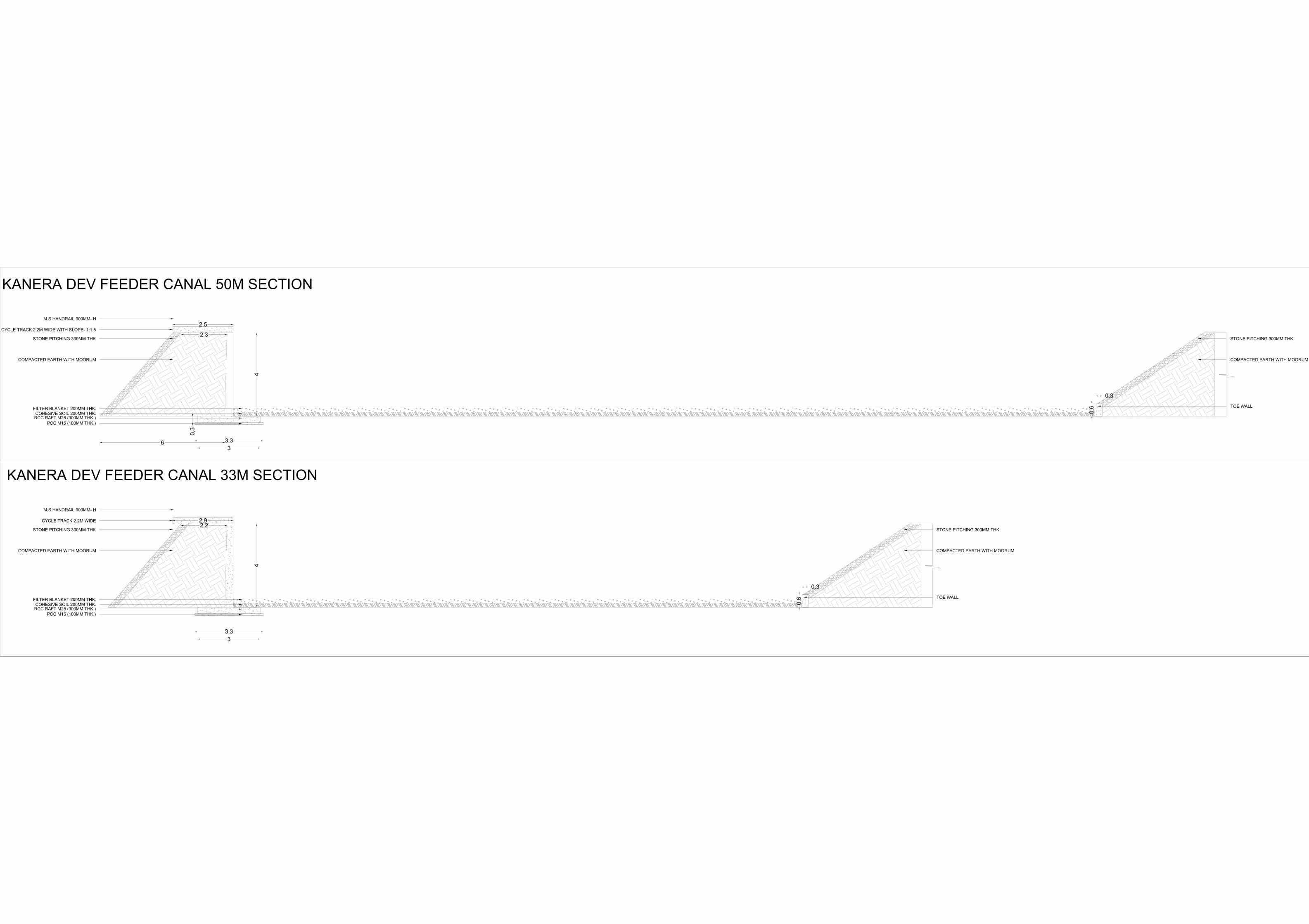
2. CONCEPTUAL CROSS SECTIONS

0,3
0,6
4
2,9
2,2
3
3,3
0,3
4,3
2,9
2,2
3
3,3
0
0,3
1
4
2,9
2,2
3
3,3
KANERA DEV FEEDER CANAL 22M SECTION
KANERA DEV FEEDER CANAL 11M SECTION
KANERA DEV FEEDER CANAL 10M SECTION
STONE PITCHING 300MM THK
COMPACTED EARTH WITH MOORUM
TOE WALL
STONE PITCHING 300MM THK
COMPACTED EARTH WITH MOORUM
TOE WALL
STONE PITCHING 300MM THK
COMPACTED EARTH WITH MOORUM
TOE WALL
CYCLE TRACK 2.2M WIDE
STONE PITCHING 300MM THK
COMPACTED EARTH WITH MOORUM
FILTER BLANKET 200MM THK.
COHESIVE SOIL 200MM THK.
RCC RAFT M25 (300MM THK.)
PCC M15 (100MM THK.)
CYCLE TRACK 2.2M WIDE
STONE PITCHING 300MM THK
COMPACTED EARTH WITH MOORUM
FILTER BLANKET 200MM THK.
COHESIVE SOIL 200MM THK.
RCC RAFT M25 (300MM THK.)
PCC M15 (100MM THK.)
CYCLE TRACK 2.2M WIDE
STONE PITCHING 300MM THK
COMPACTED EARTH WITH MOORUM
FILTER BLANKET 200MM THK.
COHESIVE SOIL 200MM THK.
RCC RAFT M25 (300MM THK.)
PCC M15 (100MM THK.)
M.S HANDRAIL 900MM- H
M.S HANDRAIL 900MM- H
M.S HANDRAIL 900MM- H
0,3
0,6
4
2.5
2.3
6
0,3
3
3,3
0,3
0,6
4
2,9
2,2
3
3,3
KANERA DEV FEEDER CANAL 50M SECTION
KANERA DEV FEEDER CANAL 33M SECTION
KANERA DEV FEEDER CANAL 22M SECTION
CYCLE TRACK 2.2M WIDE WITH SLOPE- 1:1.5
STONE PITCHING 300MM THK
COMPACTED EARTH WITH MOORUM
FILTER BLANKET 200MM THK.
COHESIVE SOIL 200MM THK.
RCC RAFT M25 (300MM THK.)
PCC M15 (100MM THK.)
STONE PITCHING 300MM THK
COMPACTED EARTH WITH MOORUM
TOE WALL
STONE PITCHING 300MM THK
COMPACTED EARTH WITH MOORUM
TOE WALL
CYCLE TRACK 2.2M WIDE
STONE PITCHING 300MM THK
COMPACTED EARTH WITH MOORUM
FILTER BLANKET 200MM THK.
COHESIVE SOIL 200MM THK.
RCC RAFT M25 (300MM THK.)
PCC M15 (100MM THK.)
M.S HANDRAIL 900MM- H
M.S HANDRAIL 900MM- H
Selection of an Agency for Redevelopment of Kanera Dev Feeder Canal Under Smart City Mission
31 | P a g e
3. PROJECT COST ESTIMATION

Redevelopment of Kanaradev Feeder Canal under Sagar Smart City Projects
Sl. No. Description of Items Estimated Cost1 Canal Lining And Pitching 3,83,60,920.00₹ 2 Cycle Track 1,05,93,436.00₹ 3 Plantation And Beautification 2,69,590.00₹ 4 Retaining Wall 5,91,66,400.00₹ 5 Street Furniture And Wastebins 8,24,000.00₹
Total Project Cost 10,92,14,346.00₹
Project Name: Redevelopment of Kanaradev Feeder Canal under Sagar Smart City Projects
SAGAR SMART CITY LIMITED COST ABSTRACT PAGE 1| 1
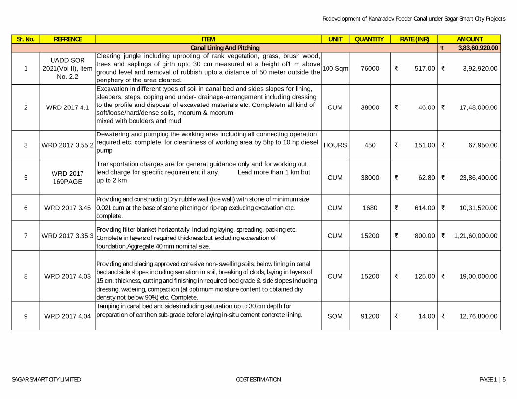
Redevelopment of Kanaradev Feeder Canal under Sagar Smart City Projects
Sr. No. REFRENCE ITEM UNIT QUANTITY RATE (INR) AMOUNT3,83,60,920.00₹
1UADD SOR
2021(Vol II), Item No. 2.2
Clearing jungle including uprooting of rank vegetation, grass, brush wood,trees and saplings of girth upto 30 cm measured at a height of1 m aboveground level and removal of rubbish upto a distance of 50 meter outside theperiphery of the area cleared.
100 Sqm 76000 517.00₹ 3,92,920.00₹
2 WRD 2017 4.1
Excavation in different types of soil in canal bed and sides slopes for lining, sleepers, steps, coping and under- drainage-arrangement including dressing to the profile and disposal of excavated materials etc. CompleteIn all kind of soft/loose/hard/dense soils, moorum & moorum mixed with boulders and mud
CUM 38000 46.00₹ 17,48,000.00₹
3 WRD 2017 3.55.2Dewatering and pumping the working area including all connecting operation required etc. complete. for cleanliness of working area by 5hp to 10 hp diesel pump
HOURS 450 151.00₹ 67,950.00₹
5 WRD 2017 169PAGE
Transportation charges are for general guidance only and for working out lead charge for specific requirement if any. Lead more than 1 km but up to 2 km CUM 38000 62.80₹ 23,86,400.00₹
6 WRD 2017 3.45Providing and constructing Dry rubble wall (toe wall) with stone of minimum size 0.021 cum at the base of stone pitching or rip-rap excluding excavation etc. complete.
CUM 1680 614.00₹ 10,31,520.00₹
7 WRD 2017 3.35.3Providing filter blanket horizontally, Including laying, spreading, packing etc. Complete in layers of required thickness but excluding excavation of foundation.Aggregate 40 mm nominal size.
CUM 15200 800.00₹ 1,21,60,000.00₹
8 WRD 2017 4.03
Providing and placing approved cohesive non- swelling soils, below lining in canal bed and side slopes including serration in soil, breaking of clods, laying in layers of 15 cm. thickness, cutting and finishing in required bed grade & side slopes including dressing, watering, compaction (at optimum moisture content to obtained dry density not below 90%) etc. Complete.
CUM 15200 125.00₹ 19,00,000.00₹
9 WRD 2017 4.04Tamping in canal bed and sides including saturation up to 30 cm depth for preparation of earthen sub-grade before laying in-situ cement concrete lining. SQM 91200 14.00₹ 12,76,800.00₹
Canal Lining And Pitching
SAGAR SMART CITY LIMITED COST ESTIMATION PAGE 1 | 5
Redevelopment of Kanaradev Feeder Canal under Sagar Smart City Projects
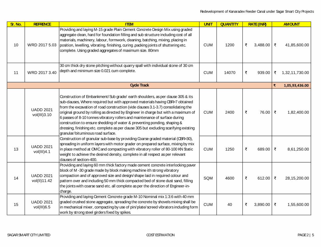
Sr. No. REFRENCE ITEM UNIT QUANTITY RATE (INR) AMOUNT
10 WRD 2017 5.03
Providing and laying M-15 grade Plain Cement Concrete Design Mix using graded aggregate clean, hard for foundation filling and sub structure including cost of all materials, machinery, labour, formwork, cleaning, batching, mixing, placing in position, levelling, vibrating, finishing, curing ,packing joints of shuttering etc. complete. Using graded aggregates of maximum size. 80mm
CUM 1200 3,488.00₹ 41,85,600.00₹
11 WRD 2017 3.40
30 cm thick dry stone pitching without quarry spall with individual stone of 30 cm depth and minimum size 0.021 cum complete. CUM 14070 939.00₹ 1,32,11,730.00₹
₹ 1,05,93,436.00
UADD 2021 vol(III)3.10
Construction of Embankment/Sub grade/ earth shoulders, as per clause 305 & its sub-clauses, Where required but with approved materials having CBR>7 obtained from the excavation of road construction (vide clauses 3.1-3.7) consolidating the original ground by rolling as directed by Engineer in charge but with a maximum of 6 passes of 8-10 tonnes vibratory rollers and maintenance of surface during construction to ensure shedding of water & preventing ponding, shaping & dressing, finishing etc. complete as per clause 305 but excluding scarifying existing granular/bituminous road surface.
CUM 2400 76.00₹ 1,82,400.00₹
13 UADD 2021 vol(III)4.1
Construction of granular sub-base by providing Coarse graded material (CBR>30), spreading in uniform layers with motor grader on prepared surface, mixing by mix in place method at OMC and compacting with vibratory roller of 80-100 KN Static weight to achieve the desired density, complete in all respect as per relevant clauses of section-400.
CUM 1250 689.00₹ 8,61,250.00₹
14 UADD 2021 vol(II)11.42
Providing and laying 60 mm thick factory made cement concrete interlocking paver block of M -30 grade made by block making machine ith strong vibratory compaction and of approved size and design/shape laid in required colour and pattern over and including 50 mm thick compacted bed of stone dust sand, filling the joints with coarse sand etc. all complete as per the direction of Engineer-in-charge.
SQM 4600 612.00₹ 28,15,200.00₹
15 UADD 2021 vol(III)6.5
Providing and laying Cement Concrete grade M-10 Nominal mix 1:3:6 with 40 mm graded crushed stone aggregate, spreading the concrete by shovels mixing shall be in mechanical mixer, compacting by use of pin/plate/screed vibrators including form work by strong steel girders fixed by spikes.
CUM 40 3,890.00₹ 1,55,600.00₹
Cycle Track
SAGAR SMART CITY LIMITED COST ESTIMATION PAGE 2 | 5

Redevelopment of Kanaradev Feeder Canal under Sagar Smart City Projects
Sr. No. REFRENCE ITEM UNIT QUANTITY RATE (INR) AMOUNT
16 UADD 2021 vol(III)8.2
Providing and laying at or near ground level Pre-cast kerb stone of M-25 grade in position to the required line, level and curvature jointed with cement mortar 1:3 (1 cement: 3 coarse sand) thickness of joints except at sharp curve shall not to more than 5mm) including making drainage opening wherever required complete as per direction of Engineer-in-charge.
CUM 24 5,509.00₹ 1,32,216.00₹
18 8.4 2021 UADD
Providing and fixing of retro-reflectorized cautionary, mandatory and informatory sign board as per IRC 67-2012 made of high intensity Micro Prismatic Grade Sheeting (Type IV) vide IRC : 67-2012 clause 6.7.3.2 & clause 801.3.3 of MORT&H firxed over Aluminium composite material sheet with thermoplastic core of Low density Polyethylene (LDPE) between two thick skins/sheets of aluminium with overall thickness of 4mm and aluminium skin of thickness 0.3 mm on both side, the ACM shall conform to Table 6.1 of IRC : 67-2012 Table 800-1 of MORT&H specifications and High Intensity Micro Prismatic Grade Sheeting shall conform of Table 6.6 of IRC 67-2012 & table 800.3 of MORT&H specifications. In line with clause 6.8 of IRC : 67- 2012 & clause 801.3.7 of MORT&H the messages (legends, numerals, letters etc.) & borders shall be screen printed or of cut out from transparent durable overlay or cut out from the same type of reflective sheeting for cautionary/ mandatory signs. Screen printing shall be processed & finished with materials and in a manner specified by the sheeting manufacturer supported on MS angle iron sign post of size 75mm x 75mm x 6mm fixed to ground by means of properly designed foundation of dimension 450 x 450 x 600 mm with M-15 grade concrete. The ACM sheet shall be fixed to the post with minimum four number breakaway bolts & supported with a back support frame of 25mm x 25mm x 3mm angle. 7 years Warranty for Retro Reflective Sheeting to be provided from the original sheeting manufacturer as per clause 6.9 of IRC : 67-2012 & a certificate of having the
�shee ng tested for co-efficient of retro reflec on, specular gloss and fungus resistance, dy time colour and luminance, shrinakge, flexibility, linear removal, adhesion, Impact resistance, 3 year outdoor weathering and its having passed this test from an independent test lab as per clause 6.7 of IRC : 67-2012 for the product offered shall be submitted by the contractor.90 cm equilateral triangle
EACH 125 3,954.00₹ 4,94,250.00₹
19 UADD 2021 vol(III)8.17
Providing, fixing and erecting 50 mm dia M.S. pipe (medium class) railing in 3 rows duly painted on medium weight steel channels (ISMC series) 100 mm x 50 mm, 1.8 m height, 1.2 meters high above ground, 2 m centre to centre, complete as per approved drawings as per relevant clauses of section-800 of specifications.
METER 4000 1,486.00₹ 59,44,000.00₹
20 UADD 2021 vol(II)13.48.2
Painting with silicon and acrylic emulsion based water thinnable sealer of approved brand and manufacture on wet or patchy portion of plastered surfaces: SQM 120 71.00₹ 8,520.00₹
SAGAR SMART CITY LIMITED COST ESTIMATION PAGE 3 | 5
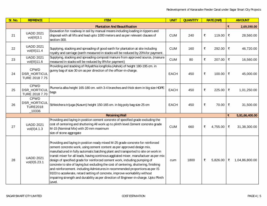
Redevelopment of Kanaradev Feeder Canal under Sagar Smart City Projects
Sr. No. REFRENCE ITEM UNIT QUANTITY RATE (INR) AMOUNT
₹ 2,69,590.00
21 UADD 2021 vol(III)3.1
Excavation for roadway in soil by manual means including loading in tippers and disposal with all lifts and lead upto 1000 meters and as per relevant clauses of section-300.
CUM 240 119.00₹ 28,560.00₹
22 UADD 2021 vol(III)11.4 Supplying, stacking and spreading of good earth for plantation at site including
royalty and carriage (earth measured in stacks will be reduced by 20% for payment.CUM 160 292.00₹ 46,720.00₹
23 UADD 2021 vol(III)11.6
Supplying, stacking and spreading compost/manure from approved source, (manure measured in stacks will be reduced by 8% for payment) CUM 80 207.00₹ 16,560.00₹
24CPWD
DSR_HORTICULTURE 2018 7.75
Providing and stacking of Polyalthia longifolia (Ashok) of height 180-195 cm. in gunny bag of size 30 cm as per direction of the officer-in-charge.
EACH 450 100.00₹ 45,000.00₹
25CPWD
DSR_HORTICULTURE 2018 7.70
Plumeria alba height 165-180 cm. with 3-4 branches and thick stem in big size HDPE bags
EACH 450 225.00₹ 1,01,250.00₹
26
CPWD DSR_HORTICUL
TURE2018 _10336
Schleichera trijuga (Kusum) height 150-165 cm. in big poly bag size 25 cm EACH 450 70.00₹ 31,500.00₹
5,91,66,400.00₹
27 UADD 2021 vol(II)4.1.3
Providing and laying in position cement concrete of specified grade excluding the cost of centering and shuttering All work up to plinth level.Cement concrete grade M-15 (Nominal Mix) with 20 mm maximumsize of stone aggregate
CUM 660 4,755.00₹ 31,38,300.00₹
28 UADD 2021 vol(II)5.23.1
Providing and laying in position ready mixed M-25 grade concrete for reinforced cement concrete work, using cement content as per approved design mix, manufactured in fully automatic batching plant and transported to site on work in transit mixer for all leads, having continous aggitated mixer, manufactuer as per mix design of specified grade for reinforced cement work, including pumping of concrete to site of laying but excluding the cost of centering, shuttering, finishing and reinforcement. including Admixtures in recommended proportions as per IS 9103 to accelerate, retard setting of concrete, improve workability without impairing strength and durability as per direction of Engineer-in-charge. Upto Plinth Level.
cum 1800 5,826.00₹ 1,04,86,800.00₹
Plantation And Beautification
Retaining Wall
SAGAR SMART CITY LIMITED COST ESTIMATION PAGE 4 | 5

Redevelopment of Kanaradev Feeder Canal under Sagar Smart City Projects
Sr. No. REFRENCE ITEM UNIT QUANTITY RATE (INR) AMOUNT
29 UADD 2021 VOL II 5.23.2
Providing and laying in position ready mixed M-25 grade concrete for reinforced cement concrete work, using cement content as per approved design mix, manufactured in fully automatic batching plant and transported to site on work in transit mixer for all leads, having continous aggitated mixer, manufactuer as per mix design of specified grade for reinforced cement work, including pumping of concrete to site of laying but excluding the cost of centering, shuttering, finishing and reinforcement. including Admixtures in recommended proportions as per IS 9103 to accelerate, retard setting of concrete, improve workability without impairing strength and durability as per direction of Engineer-in-charge. Above
CUM 2450 5,980.00₹ 1,46,51,000.00₹
30 UADD 2021 VOL II 5.11
Reinforcement for R.C.C. work including straightening, cutting, bending, placing in position and binding upto floor level including cost of binding wire, wastage and over laps upto 12mm horizontal/ inclined position of reinforcement bars in slab and beams, plinth, chajjas, lintels, upto 4.5m vertical length of reinforcement in wall columns (over laps shall be provided as per requirement of IS : 13920; IS 456 & SP : 34) etc. complete.Thermo-Mechanically Treated bars. (Fe 500 D or more)
KG 522750 58.00₹ 3,03,19,500.00₹
31 UADD 2021 VOL II 19.1.1 Centering and shuttering including strutting, propping stretching etc. complete for
and removal of form work by sheet plate or ply wood shuttering for :Foundations, footings, bases of columns, etc. For mass concrete.
SQM 1400 160.00₹ 2,24,000.00₹
32 UADD 2021 VOL II 19.1.
Centering and shuttering including strutting, propping stretching etc. complete for and removal of form work by sheet plate or ply wood shuttering for :Walls (any thickness) including attached pilasters, butteresses, plinthand string courses etc
SQM 1200 289.00₹ 3,46,800.00₹
₹ 8,24,000.00 33 NON-SOR Garden outdoor Cast Iron Bench-3 by Venusto INDIA(AMAZON) EACH 40 12,500.00₹ 5,00,000.00₹ 34 Gem Portal Dustbin Container 60 Liters Stainless Steel(without GST) EACH 40 8,100.00₹ 3,24,000.00₹
10,92,14,346.00₹ Sub Total (A)
Street Furniture And Wastebins
SAGAR SMART CITY LIMITED COST ESTIMATION PAGE 5 | 5