Embed Size (px)
Citation preview

Feedback Control for Steering Needles Through 3D Deformable Tissue Using Helical Paths
Kris Hauser, Ron Alterovitz, Nuttapon Chentanez, Allison Okamura, Ken Goldberg.
Yajia Zhang
Background
• Needles are used in medicine for a wide range of diagnostic and therapy delivery procedures.
• Needle tip must be positioned accurately at the target in the tissue. But the process requires skills. Errors may occur even under image guidance.
• Feedback controller that steers the needle and places the needle tip at the target even under the perturbation of the tissue and deflection of the needle trajectory.
Background
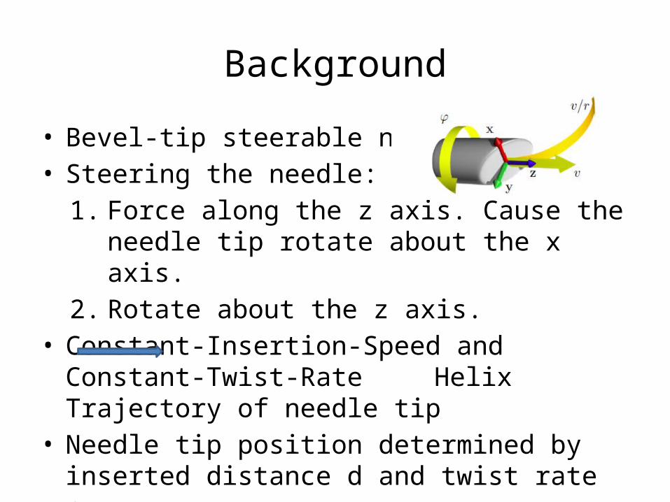
• Bevel-tip steerable needle• Steering the needle:
1. Force along the z axis. Cause the needle tip rotate about the x axis.
2. Rotate about the z axis. • Constant-Insertion-Speed and Constant-Twist-Rate
Helix Trajectory of needle tip• Needle tip position determined by inserted distance
d and twist rate φ.

Goal
• Feedback controller to steer the bevel-tip needle with:
1.Constant insertion speed2.Different twist rate
to reach the target in the tissue.

Why real time planner• Deformation of the tissue. Cause position of the target change.
• Deflection of the planned trajectory.
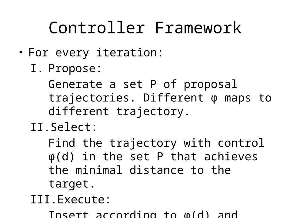
Controller Framework• For every iteration:
I. Propose: Generate a set P of proposal trajectories. Different φ maps to different trajectory.
II. Select:Find the trajectory with control φ(d) in the set P that achieves the minimal distance to the target.
III. Execute:Insert according to φ(d) and constant velocity for time Δt.

I. ProposeGenerate Proposal Trajectories
• When inserting the needle into the tissue, we build the coordinate frame according to the position of the needle tip.
Constant-Twist-Rate Helical Paths
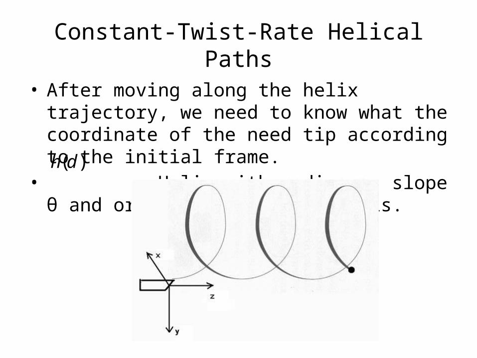
• After moving along the helix trajectory, we need to know what the coordinate of the need tip according to the initial frame.
• :Helix with radius a, slope θ and oriented along the z axis.
)(dh
Constant-Twist-Rate Helical Paths
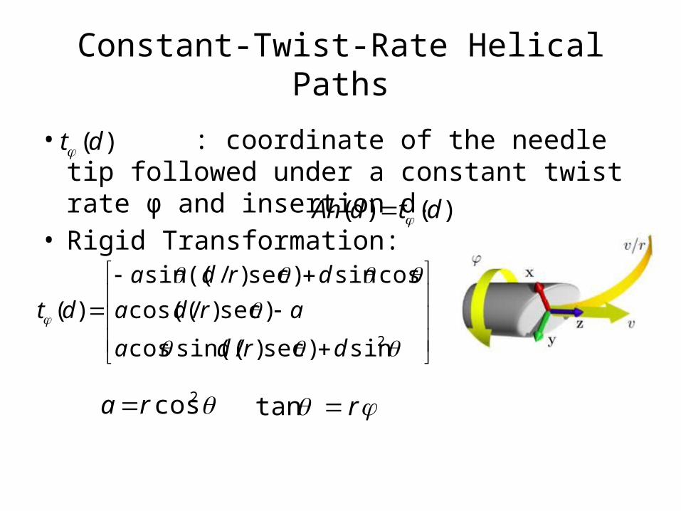
• : coordinate of the needle tip followed under a constant twist rate φ and insertion d.
• Rigid Transformation:
)(dt
)()( dtdAh
2sin)sec)/sin((cos
)sec)/cos((
cossin)sec)/((sin
)(
drda
arda
drda
dt
2cosra rtan
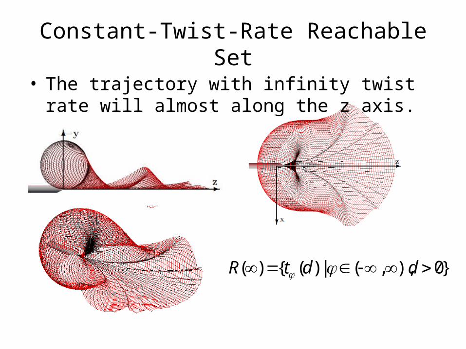
Constant-Twist-Rate Reachable Set• The trajectory with infinity twist rate will almost
along the z axis.
}0),,(|)({)( ddtR
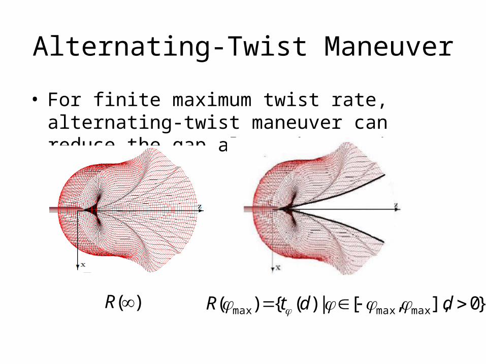
Alternating-Twist Maneuver
• For finite maximum twist rate, alternating-twist maneuver can reduce the gap along the z axis.
}0],,[|)({)( maxmaxmax ddtR )(R

Alternating-Twist Maneuver
• To fill in the gap, we consider the maneuver that makes a full turn of the helix with twist rate , and another with twist rate

II. SelectChoose the trajectory with minimum distance to target
• Minimize • + proposal trajectories in
the gap• Auxiliary function is used to calculate a tight
lower bound of given a region R.
||target)(||),( dtdf }0,|||),{( max ddS
)(RfL),( df

Branch-and-Bound• A search tree recursively split the space into
subregions. We maintain the helix * and insertion distance d* which give the minimum value of f. If of subregion R gives value larger than f, we can safely prune the region. We continue the process until f achieves an ε tolerance.
)(RfL

III. Execute
• Insert according to the select trajectory for time Δt or some distance Δd.

Simulation
Simulation Result
• Accuracy: The final distance from the needle tip to the target when the controller terminates.
• Reference controller: A refresh occurs every 2%r of insertion distance, maximum twist rate = 10π rad/rmax
Simulation Result
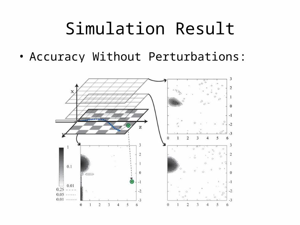
• Accuracy Without Perturbations:
Simulation Result
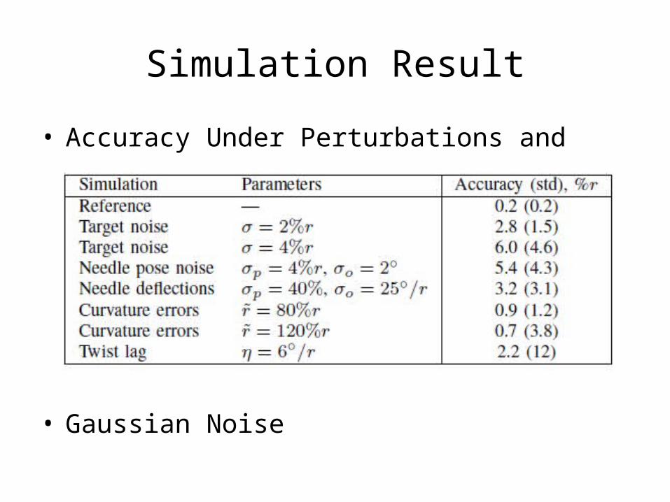
• Accuracy Under Perturbations and Modeling Errors:
• Gaussian Noise

Possible Improvement
• Avoid the obstaclesSet intermediate Target’. When reaching Target’, we may just assume the Target moved.
Target
Target’

Issue About Real Time Planning
• How often should we re-plan?• The reference controller refreshes after inserting
length s= 2%r to achieve high accuracy.• What if the deformation and deflection do not
happen (or some tiny changes)? • Complex system may require intense computation in
re-planning.