Embed Size (px)
Citation preview

2
Object
• To become familiar with the modules and how they operate.

3
Equipment Required
• 1 OU150A Operation Amplifier Unit • 1 AU150B Attenuator Unit • 1 PA150C Pre-amplifier Unit • 1 SA150D Servo Amplifier • 1 PS150E Power Supply • 1 MT150F Motor-Tacho Unit • 1 IP150H Input potentiometer Unit • 1 OP150K Output Potentiometer Unit • 1 LU150L Load Unit

4
Preliminary Procedure
• Attach Operational Amplifier Unit, Attenuator Unit, Pre-amplifier unit, Servo Amplifier unit, Power Supply unit, Motor unit and Input and Output potentiometer units to the baseplate by means of their magnetic feet.

5
Discussion
• A servomechanism or servo is an automatic device that uses error-sensing feedback to correct the performance of a mechanism. The term correctly applies only to systems where the feedback or error-correction signals help control mechanical position or other parameters.

6
Discussion
• Modern servomechanisms use solid state power amplifiers, usually built from MOSFET or thyristor devices. Small servos may use power transistors.

7
Applications
• First used in military fire-control • Marine navigation equipment• Speed governing of engines • Automatic steering of ships• Automatic control of guns • Electromechanical analog computers.

8
Applications• Today, servomechanisms are employed in almost every industrial field. Among the
applications are:• cutting tools for discrete parts manufacturing• rollers in sheet • web processes• elevators• automobile • machine tools • aircraft engines• robots• remote manipulators • Telescopes• antennas• space vehicles• satellite tracking antennas ,remote control airplanes, anti -aircraft gun control systems,
mechanical knee and arm prostheses, and tape, disk, and film drives.
9
MS 150 Modular Servo System
• Each of the units of this equipment is fitted with magnetic feet and can be attached to the base-board in any desired position.
• The main power supplies for the Servo Amplifier unit and the Motor Tacho unit are fed through the cables terminating in octal plugs fitted to both Motor-Tacho and Servo Amplifier unit.

10
MS 150 Modular Servo System
• The lead from the motor should be plugged into the Servo Amplifier and that from the Amplifier into the Power Supply.
• Both Power Supply unit and Servo Amplifier unit are fitted with 4mm sockets from which ±15 d.c supplies can be drawn to operate all other units of the system.
• For each experiment a patch diagram is included to show all the necessary connections to be made with patch leads provided.

11
Power Supply Unit (PS150E)
• This unit supplies a 24v d.c 2A unregulated supply to the motor through an 8-way connector to the Servo Amplifier, as it is this unit that controls the motor.
• On the front panel there are two sets of 4mm sockets to provide ±15v stabilized d.c supplies to operate the smaller amplifiers and provide reference voltage. The power supply unit in laboratory tutorials is represented as in figure-1.1.

12
Power Supply Unit (PS150E)

13
Motor-Tacho Unit (MT150F)
• This Unit is made up of three parts • 1. A d.c series-wound split-field motor which
has an extended shaft, and onto which can be fixed the magnetic brake or inertia disc.
• 2. A d.c tacho-generator with output on the top of the unit
• 3. For control experiments, there is a low-speed shaft driven by a 30:1 reduction gearbox.

14
Motor-Tacho Unit (MT150F)

15
Servo Amplifier Unit (SA150D)
• This unit contains the transistors which drive the motor in either direction. On the front panel connection are provided for patching the armature for different modes of control (e.g. Field controlled or armature controlled). The Servo Amplifier is shown in following figure.

16
Servo Amplifier Unit (SA150D)
17
Attenuator Unit (AT150B)
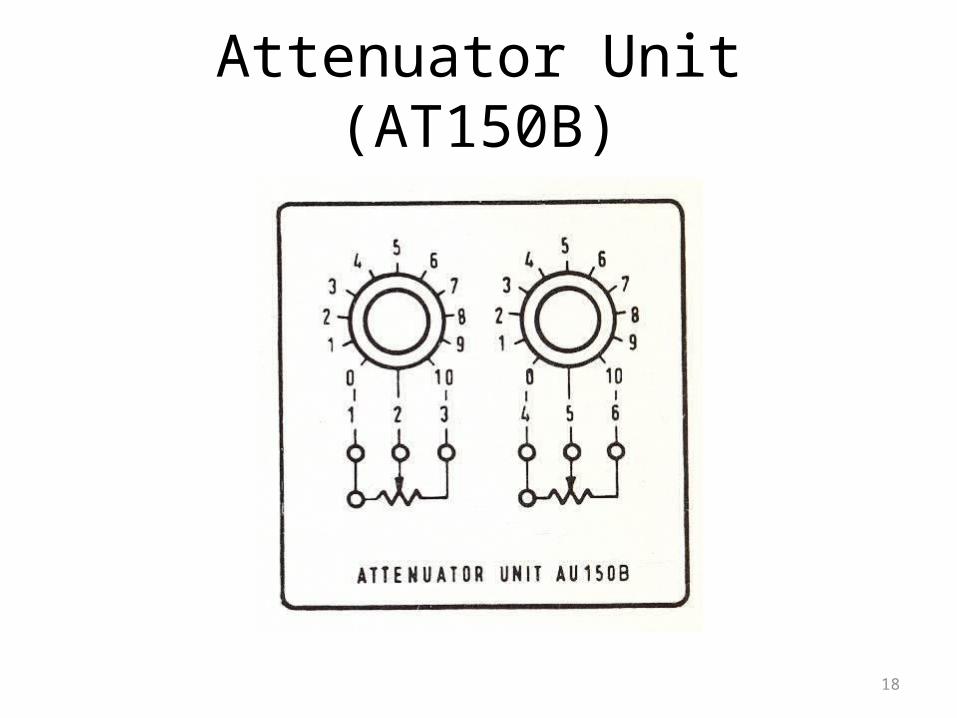
• This unit contains two variable 10KΩ potentiometers as shown in figure-1.4. The proportion of the resistance being selected is indicated by a dial graduated from 0 to 10. This unit can either provide a reference voltage when connected to a d.c source or be used as a gain control when connected to the output of an amplifier.
18
Attenuator Unit (AT150B)

19
Input and Output Potentiometer Units (IP150H & OP150K)
• These are rotary potentiometers, used in experiments on position control. The input potentiometer is used to set up a reference voltage and the output potentiometer is connected to the low speed shaft of the motor by using the push-on couplings. Figure-1.5 gives the circuit diagram for these units.

20
Input and Output Potentiometer Units (IP150H & OP150K)

21
Pre-Amplifier Unit (PA150C)
22
Pre-Amplifier Unit (PA150C)
• This provides the correct signals to drive the Servo Amplifiers in SA150D. The two inputs are effectively summed, allowing two signals to be applied (e.g. reference voltage and the tacho-generator voltage).
• A positive signal applied to either input causes the upper output (3) to go positive, the other output (4) staying near zero. A negative input causes the lower output (4) to go positive, the upper one staying near zero. The bidirectional motor drive is obtained when these outputs are linked to the Servo Amplifier inputs.

23
Operational Amplifier Unit (OU150A)
• This provides inverting voltage gain and means of summing two or more signals, as well as facilities for introducing compensation networks. Figure-1.7 gives the layout of this unit.

24
Operational Amplifier Unit (OU150A)

25
Load Unit (LU150L)
• An Aluminum disc can be mounted on the motor shaft and when rotated between the poles o the magnet of the load unit, the eddy currents generated have the effect of a brake. The strength of the magnetic brake can be controlled by the position of the magnet.

26
Lab Tasks Task#1: To connect up the motor
• You are now acquainted with sufficient units to be able to connect up the motor. The motor direction depends upon which of the two field coils is energized, and the speed upon the amount of drive voltage applied to the inputs of Servo Amplifier. In this practical we shall use one direction only, and vary the drive voltage using one of the attenuators. Set up the circuit of figure-1.8, in which the armature links are patched for armature control mode.

27
Lab Tasks

28
Lab Tasks
• Task#2: To drive the motor in field control mode 8
• Patch the F links together in order to drive the motor in field control mold.
29
Lab Assignments
• Assignment#1: Drive the armature controlled d.c motor in either direction.
• Assignment#2: Drive the filed controlled d.c motor in either direction.