Embed Size (px)
Citation preview
Federal AviationAdministration
Office of Airport Safetyand Standards Update
IESALC ConferenceOctober 23, 2017
By: Robert Bassey Airport Engineering Division
2Federal AviationAdministration
Agenda
• Overview• FAA LED Significant Safety Issue (SSI) • Advisory Circular Updates• Engineering Brief Updates
3Federal AviationAdministration
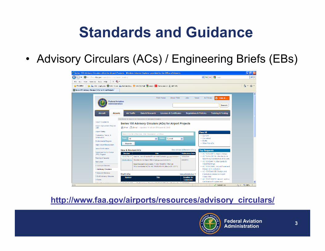
Standards and Guidance• Advisory Circulars (ACs) / Engineering Briefs (EBs)
http://www.faa.gov/airports/resources/advisory_circulars/
4Federal AviationAdministration
Administrator’s Strategic Initiative
• In FY15, FAA LOBs (ATO, AVS, ARP) established formal, repeatable processes to identify Significant Safety Issues (SSI) as part of Activity 2b within the Risk-Based Decision Making (RBDM) Strategic Initiative.
• An FAA SSI Team established a process to prioritize the LOB/SO lists and developed a prioritized list of 10 FAA-level, cross-organizational SSI.
• The FAA SMS Executive Council agreed to apply cross-organizational resources to conduct comprehensive safety risk assessments for:
• Light Emitting Diodes (LED) Lighting of Airfields, Obstacles, and Aircraft
5Federal AviationAdministration
LED Significant Safety Issue (SSI)
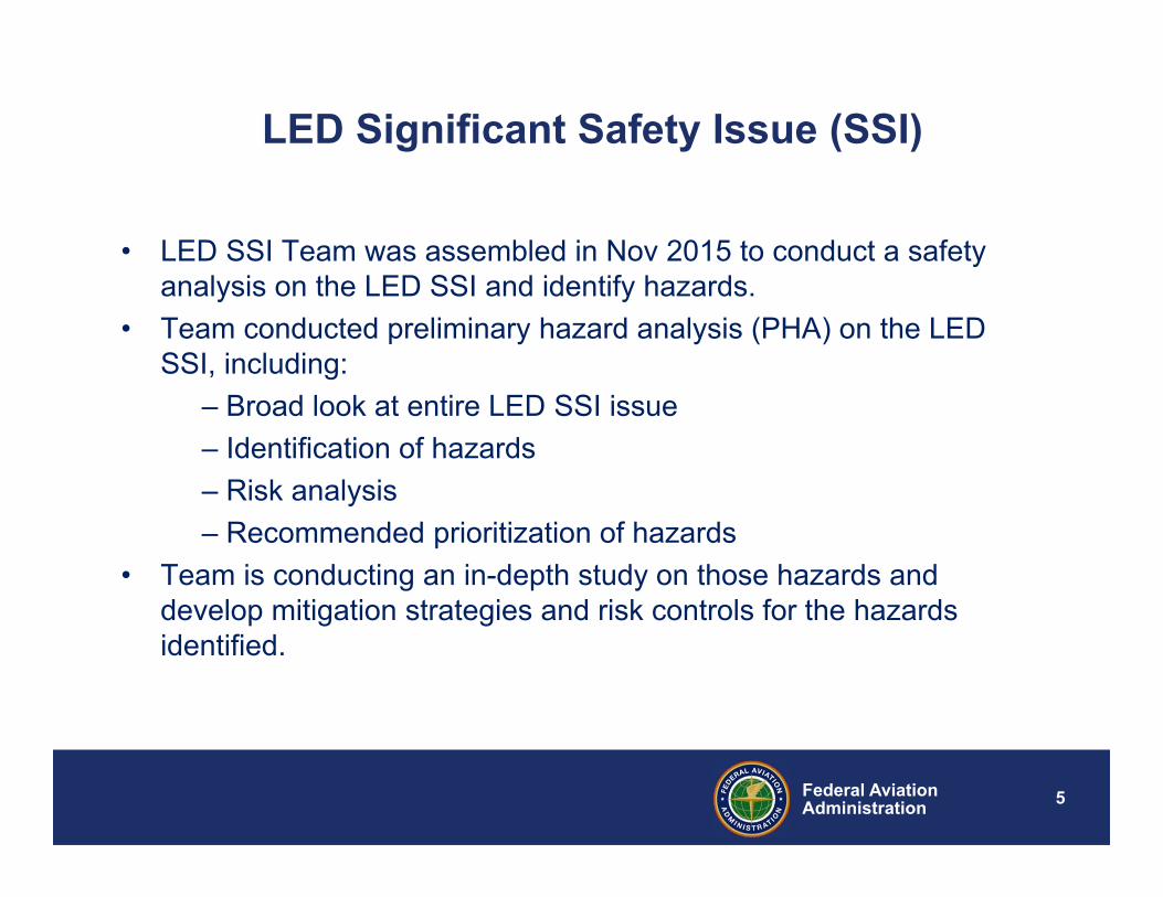
• LED SSI Team was assembled in Nov 2015 to conduct a safety analysis on the LED SSI and identify hazards.
• Team conducted preliminary hazard analysis (PHA) on the LED SSI, including:
– Broad look at entire LED SSI issue– Identification of hazards– Risk analysis– Recommended prioritization of hazards
• Team is conducting an in-depth study on those hazards and develop mitigation strategies and risk controls for the hazards identified.
6Federal AviationAdministration
Hazards being studied
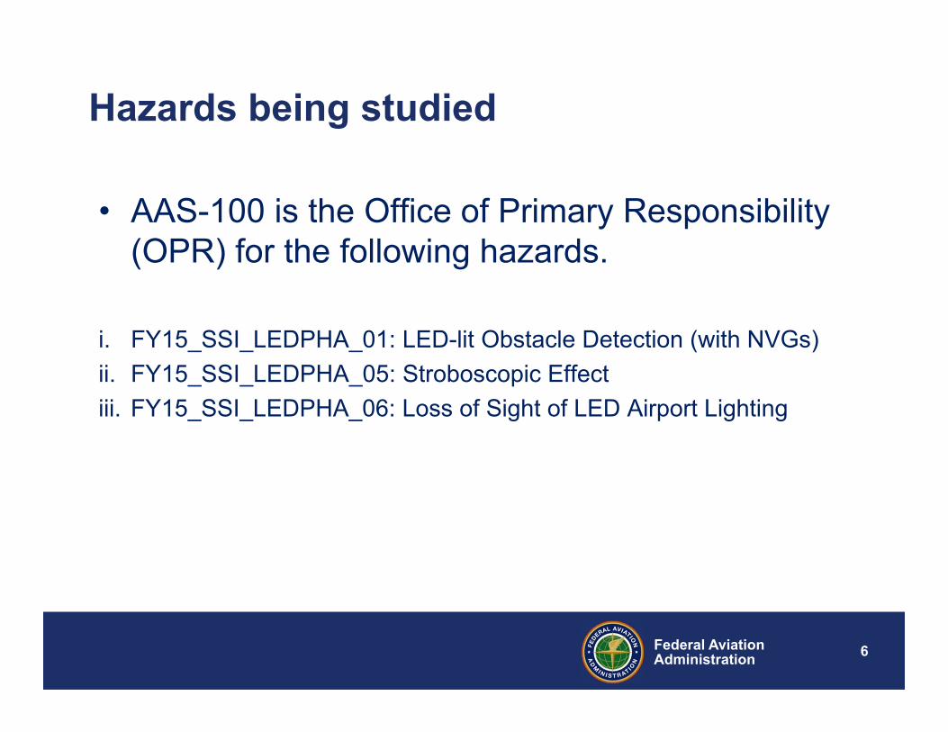
• AAS-100 is the Office of Primary Responsibility (OPR) for the following hazards.
i. FY15_SSI_LEDPHA_01: LED-lit Obstacle Detection (with NVGs)ii. FY15_SSI_LEDPHA_05: Stroboscopic Effectiii. FY15_SSI_LEDPHA_06: Loss of Sight of LED Airport Lighting
7Federal AviationAdministration
Advisory Circular Updates
8Federal AviationAdministration
AC 150/5340-30J
9Federal AviationAdministration
• Taxiway Edge Lights – Incorporated Engineering Brief (EB) #92A, Light
Spacing Guidance for New Taxiway Fillet Geometry. – Provides new guidance for taxiway edge lighting
design for new taxiway construction or rehabilitation.
Principal Changes
10Federal AviationAdministration
• PAPI Obstacle Clearance Surface (OCS) – Note added to explain flight inspection personnel
considerations when evaluating the PAPI (OCS) and objects outside the surface.
• Flight Inspection Procedures for PAPI / Visual Glideslope Indicators (VGSI) – Text update to state: “All VGSI systems servicing IFR
runways need to be commissioned as soon as the necessary survey data and funds are available”.
– Updated to explain obstacles outside the PAPI OCS may be evaluated during flight inspections
Principal Changes
11Federal AviationAdministration
• Flight Inspection Procedures for PAPI / Visual Glideslope Indicators (VGSI)– Flight check personnel will evaluate PAPI obstacle
clearance within the lateral limits of the “visible” light beam. Evaluation may exceed the standard OCS.
Principal Changes
12Federal AviationAdministration
• Counterpoise (Lightning Protection System)– Paragraph incorporates a rewrite for Counterpoise Lightning
Protection System to simplify “equipotential” and “isolation methods” for airfield lighting counterpoise installation.
• Vault – Incorporates vault recommendations per National Fire Protection
Association (NFPA) National Electric Code (NEC) guidelines.• Installation of Cables
– Incorporates National Electric Code recommendations regarding “Installation of Cables”.
Principal Changes
13Federal AviationAdministration
EB-98 “Infrared Specifications for Aviation Obstruction Light Compatibility with Night Vision Goggles”
14Federal AviationAdministration
EB-98
• Engineering Brief allows infrared emitters to be included in LED obstruction lighting fixtures.
• Engineering brief determines performance specifications for IR emitters to be incorporated into LED obstruction light fixtures.
• The specifications for the IR emitters support the operational requirement for LED-lit obstruction lights to be visible to operators in AC 7460-1 “Obstruction Marking and Lighting”.
15Federal AviationAdministration
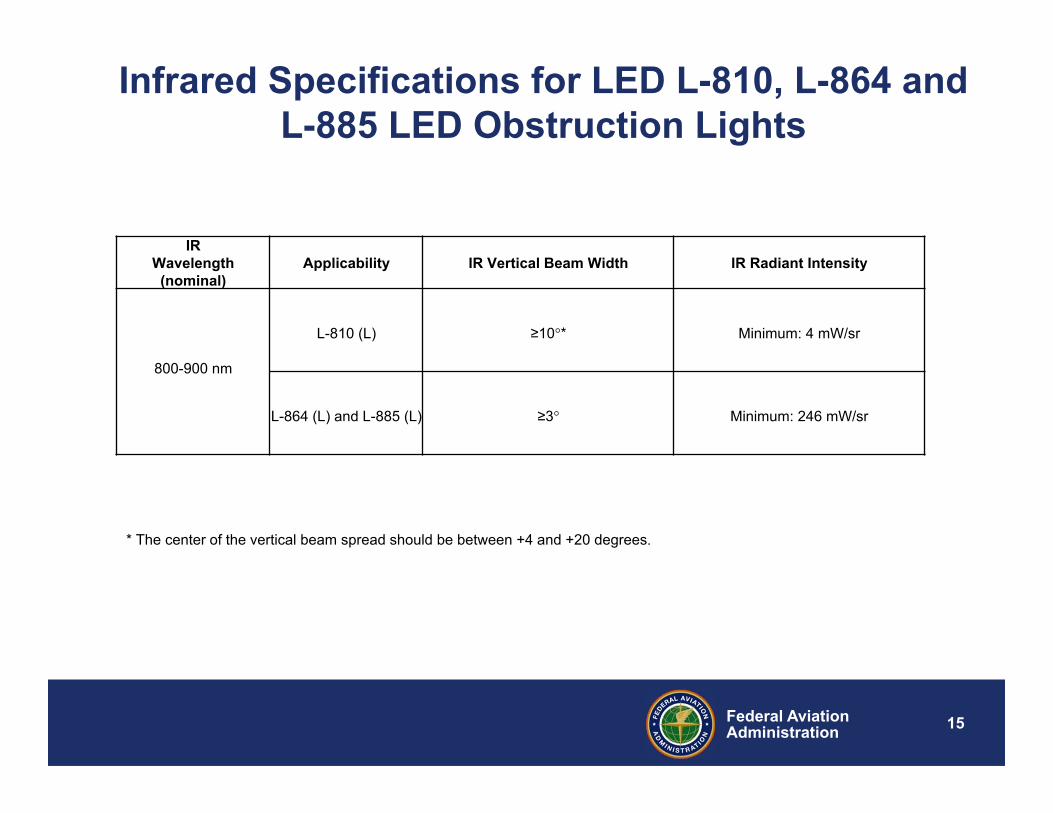
Infrared Specifications for LED L-810, L-864 and L-885 LED Obstruction Lights
IRWavelength
(nominal)Applicability IR Vertical Beam Width IR Radiant Intensity
800-900 nm
L-810 (L) ≥10°* Minimum: 4 mW/sr
L-864 (L) and L-885 (L) ≥3° Minimum: 246 mW/sr
* The center of the vertical beam spread should be between +4 and +20 degrees.
16Federal AviationAdministration
EB-95 “Additional Siting and Survey considerations for Precision
Approach path Indicator (PAPI) and Other Visual Glide Slope Indicators (VGSI)”
17Federal AviationAdministration
New requirements in FAA Order 8200.1D
FAA Order 8200.1D, United States Standard Flight Inspection Manual, defines PAPI Obstacle Clearance Surface (OCS) penetration evaluation criteria to be checked by the flight inspectors during the PAPI commissioning process. The updated document defines two new requirements:
FAA Flight Inspection will evaluate OCS penetrations to 8 nm from threshold for Type L-880 (4-box) PAPI, and may be reduced to 4 nm for a Type L-881 (2-box) PAPI.
Extends the evaluation of the obstacle clearance within the lateral limits of the visible light beam, even if it means going outside the standard 10 degree to 10 degree obstacle protection area centered on the runway.
18Federal AviationAdministration
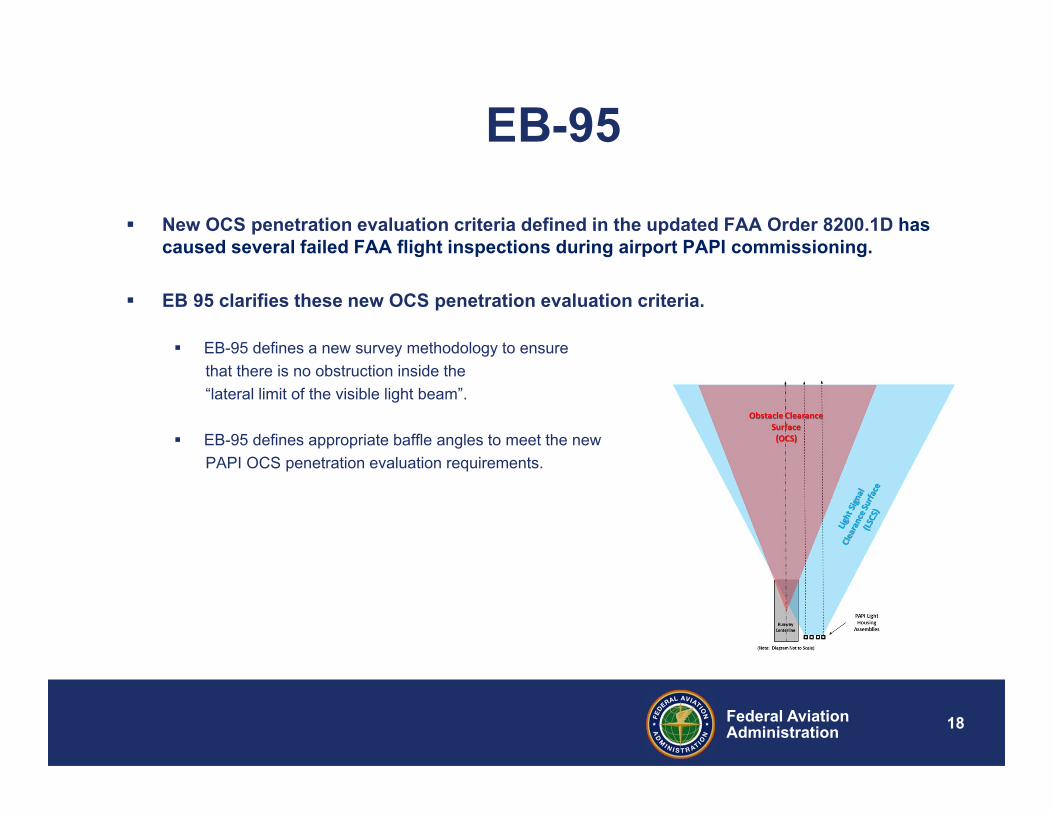
EB-95
New OCS penetration evaluation criteria defined in the updated FAA Order 8200.1D has caused several failed FAA flight inspections during airport PAPI commissioning.
EB 95 clarifies these new OCS penetration evaluation criteria.
EB-95 defines a new survey methodology to ensure that there is no obstruction inside the “lateral limit of the visible light beam”.
EB-95 defines appropriate baffle angles to meet the new PAPI OCS penetration evaluation requirements.
•Federal Aviation•Administration
FAA Signage & Markings Update
IES ALC Fall 201 Technology Meeting
Dallas, TX
October 23-26, 2017
Tom Mai
FAA, Office of Safety and Standards
Airport Engineering Division (AAS-100)
20Federal AviationAdministration
Agenda• AC 150/5340-18G• AC 150/5340-1M• Q & A
21Federal AviationAdministration
•21
AC 5340-18G (Draft Rev G) Standards for Airport Sign Systems
22Federal AviationAdministration
•22
23Federal AviationAdministration
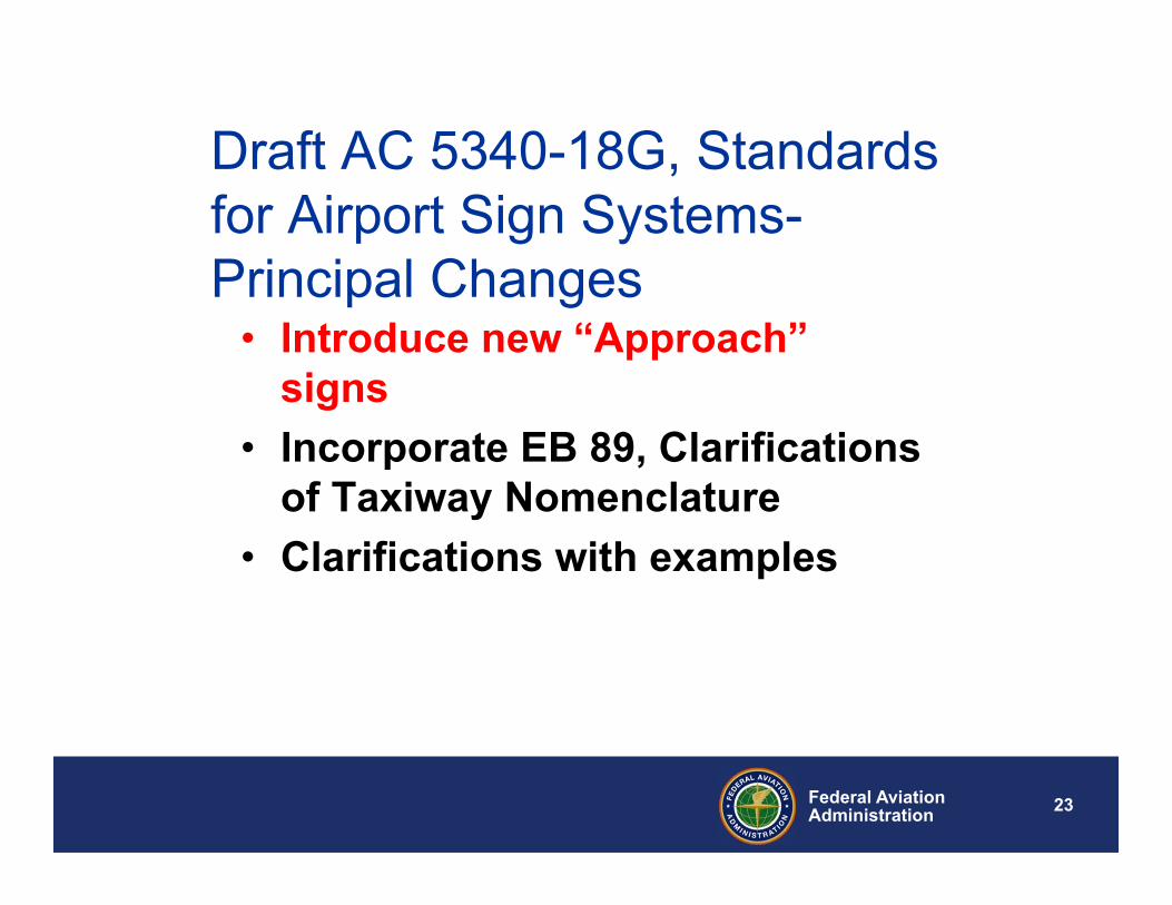
Draft AC 5340-18G, Standards for Airport Sign Systems-Principal Changes
• Introduce new “Approach” signs
• Incorporate EB 89, Clarifications of Taxiway Nomenclature
• Clarifications with examples
24Federal AviationAdministration
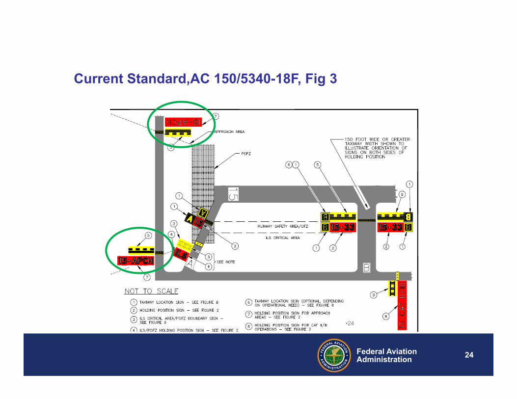
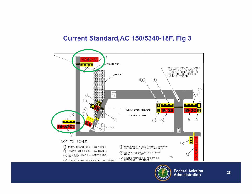
Current Standard,AC 150/5340-18F, Fig 3
•24
25Federal AviationAdministration
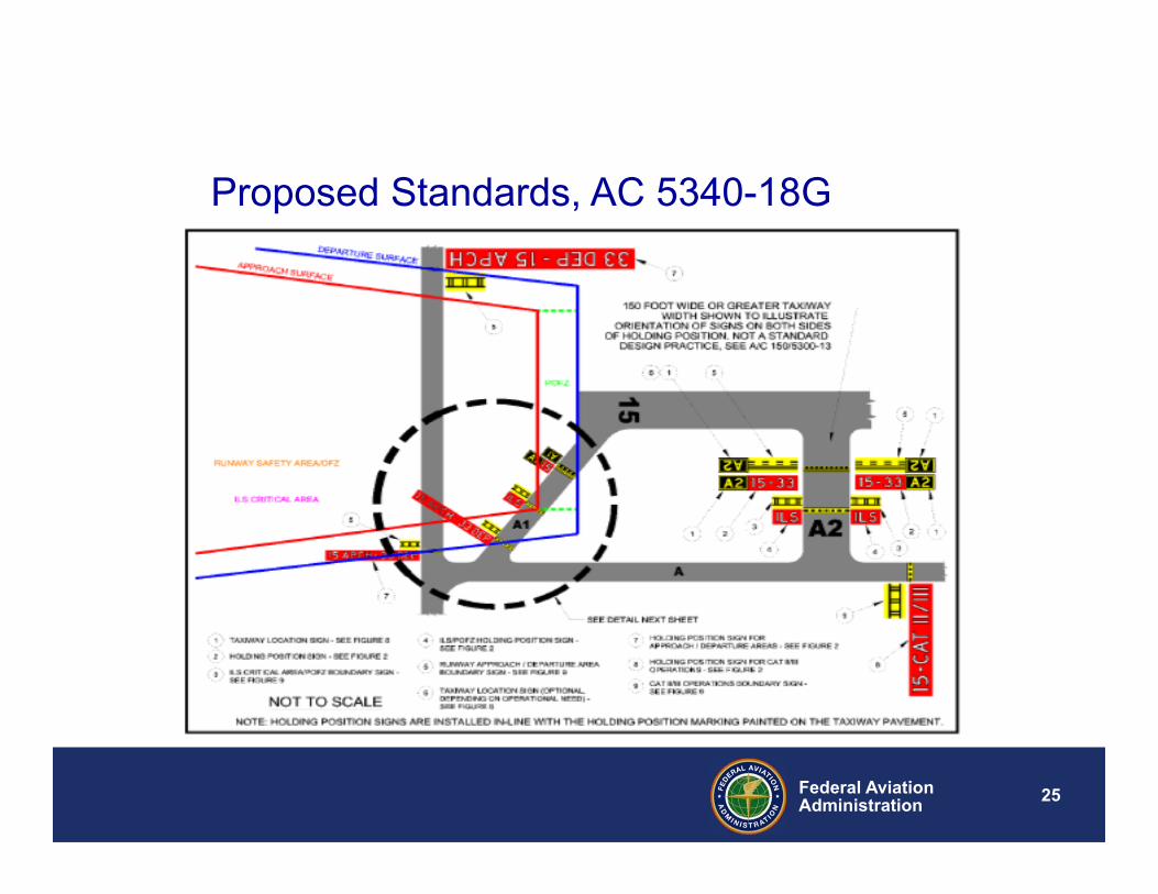
Proposed Standards, AC 5340-18G
26Federal AviationAdministration
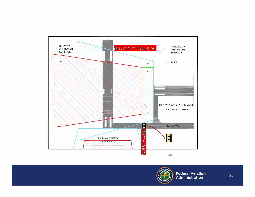
TAXIWAY A
RUNWAY SAFETY AREA/OFZ
AREA/OFZRUNWAY SAFETY
TAXIWAY A
POFZ
RUNWAY 33DEPARTURESURFACE
RUNWAY 15APPROACHSURFACE
ILS CRITICAL AREA
•26
27Federal AviationAdministration
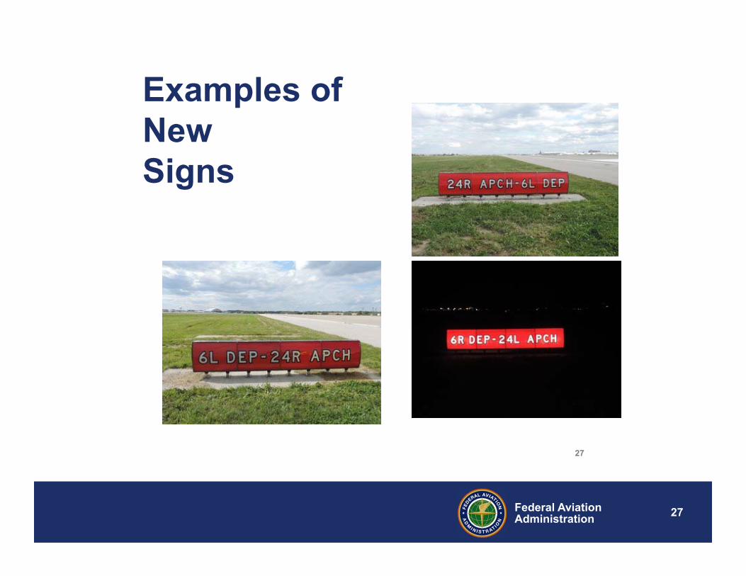
Examples of NewSigns
27
28Federal AviationAdministration
Current Standard,AC 150/5340-18F, Fig 3
•28
29Federal AviationAdministration
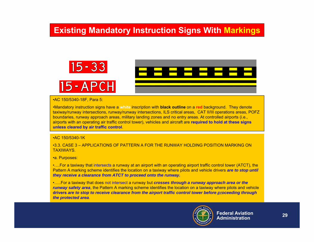
•AC 150/5340-18F, Para 5:
•Mandatory instruction signs have a white inscription with black outline on a red background. They denote taxiway/runway intersections, runway/runway intersections, ILS critical areas, CAT II/III operations areas, POFZ boundaries, runway approach areas, military landing zones and no entry areas. At controlled airports (i.e., airports with an operating air traffic control tower), vehicles and aircraft are required to hold at these signs unless cleared by air traffic control.
•AC 150/5340-1K
•3.3. CASE 3 – APPLICATIONS OF PATTERN A FOR THE RUNWAY HOLDING POSITION MARKING ON TAXIWAYS.
•a. Purposes:
•….For a taxiway that intersects a runway at an airport with an operating airport traffic control tower (ATCT), the Pattern A marking scheme identifies the location on a taxiway where pilots and vehicle drivers are to stop until they receive a clearance from ATCT to proceed onto the runway.
•…..For a taxiway that does not intersect a runway but crosses through a runway approach area or the runway safety area, the Pattern A marking scheme identifies the location on a taxiway where pilots and vehicle drivers are to stop to receive clearance from the airport traffic control tower before proceeding through the protected area.
Existing Mandatory Instruction Signs With Markings
•29
30Federal AviationAdministration
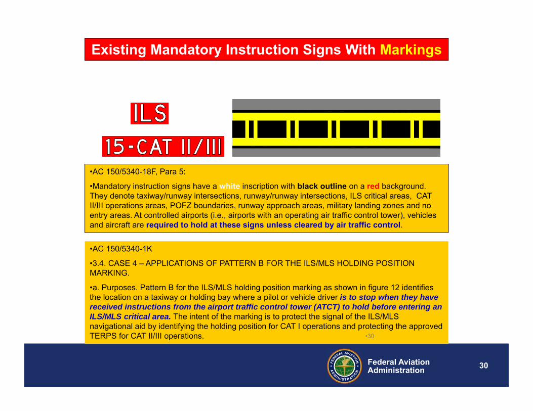
•AC 150/5340-18F, Para 5:
•Mandatory instruction signs have a white inscription with black outline on a red background. They denote taxiway/runway intersections, runway/runway intersections, ILS critical areas, CAT II/III operations areas, POFZ boundaries, runway approach areas, military landing zones and no entry areas. At controlled airports (i.e., airports with an operating air traffic control tower), vehicles and aircraft are required to hold at these signs unless cleared by air traffic control.
•AC 150/5340-1K
•3.4. CASE 4 – APPLICATIONS OF PATTERN B FOR THE ILS/MLS HOLDING POSITION MARKING.
•a. Purposes. Pattern B for the ILS/MLS holding position marking as shown in figure 12 identifies the location on a taxiway or holding bay where a pilot or vehicle driver is to stop when they have received instructions from the airport traffic control tower (ATCT) to hold before entering an ILS/MLS critical area. The intent of the marking is to protect the signal of the ILS/MLS navigational aid by identifying the holding position for CAT I operations and protecting the approved TERPS for CAT II/III operations.
Existing Mandatory Instruction Signs With Markings
•30
31Federal AviationAdministration
APPROACH HOLD ISSUES
•31
32Federal AviationAdministration
APPROACH HOLD ISSUES
• There are inconsistencies in implementing approach hold signs, marking and procedures among the nation’s airports, causing confusion among ATC, pilots, airport operators and cert inspectors.
• Protect other areas such as RSA, approach, departure, or other critical surfaces of a runway intersecting with another runway’s RSA or critical surfaces.
•32
33Federal AviationAdministration
APPROACH HOLD ISSUES (CONT.)
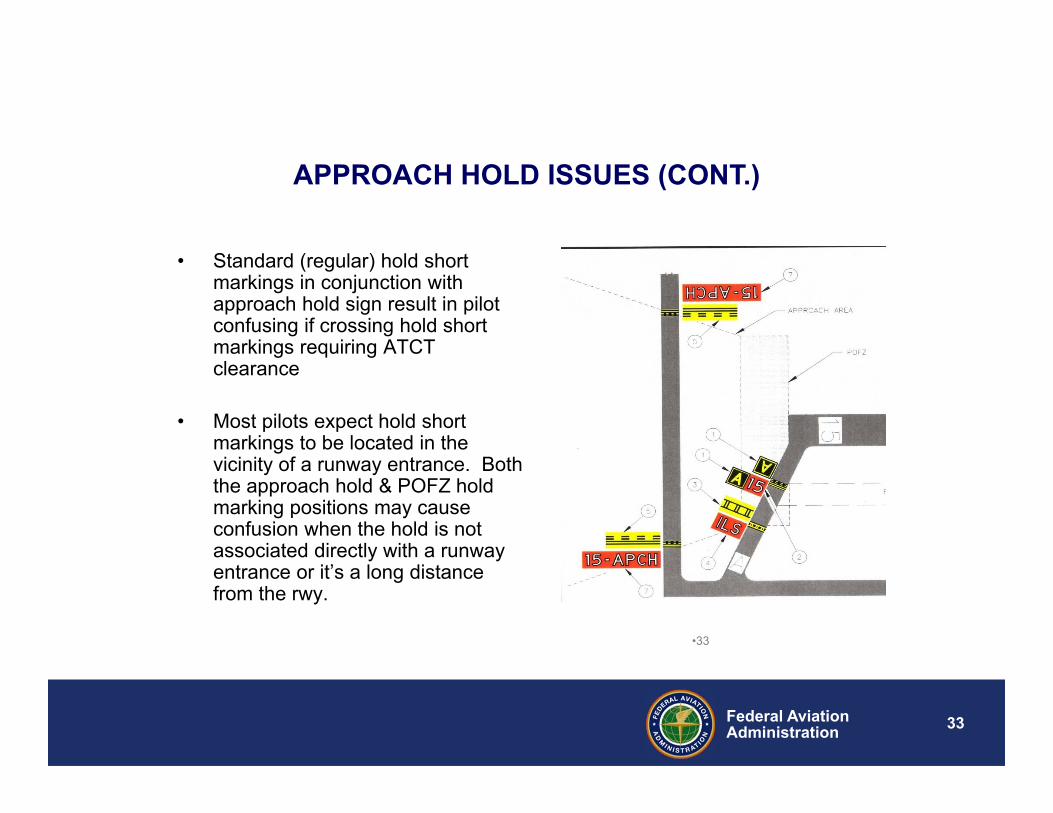
• Standard (regular) hold short markings in conjunction with approach hold sign result in pilot confusing if crossing hold short markings requiring ATCT clearance
• Most pilots expect hold short markings to be located in the vicinity of a runway entrance. Both the approach hold & POFZ hold marking positions may cause confusion when the hold is not associated directly with a runway entrance or it’s a long distance from the rwy.
•33
34Federal AviationAdministration
APPROACH HOLD ISSUES (CONT.)
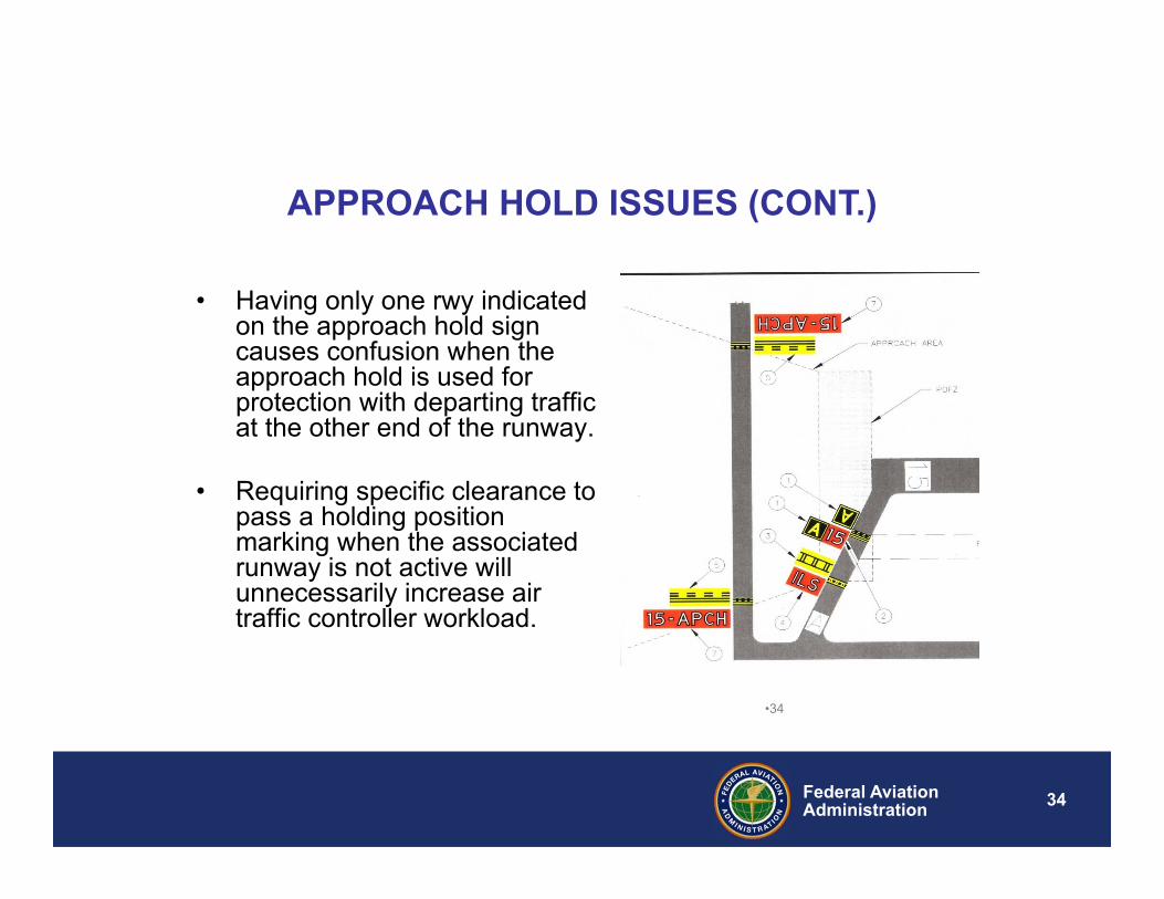
• Having only one rwy indicated on the approach hold sign causes confusion when the approach hold is used for protection with departing traffic at the other end of the runway.
• Requiring specific clearance to pass a holding position marking when the associated runway is not active will unnecessarily increase air traffic controller workload.
•34
35Federal AviationAdministration
FAA Approach Hold Workgroup/Panel
• Approach Hold Workgroup was established in 2011 to identify the issues & concerns with the approach areas.
• Chaired by RSO• Workgroup members: FAA internal, NATCA & Industry (AAAE,
ACI, ALPA)• Proposed changes to Approach Signs
• To implement the proposed changes, SRMP was formed in Oct 2012 to complete the SRM process
• ATO’s SRMD, Approach Hold Document Change Proposal SRMD (10/22/13)
• Approach Hold Signs & Markings SRMD (Sept 2017)
36Federal AviationAdministration
Airport Office (AAS) Activities/ Progress• Tech Center R&D project research was launched in 2013
to validate new signs and markings as recommended in the Safety Risk Management Document (SRMD) from the Approach Hold Workgroup.
• Evaluation of Enhanced Visual Cues for Runway Approach and Runway Safety Areas Final Report (April 2016)
• Runway Approach Hold Area Signage and Marking Study Tech Note (June 2017)
• Revise/update appropriate signs/marking (on-going)• Draft AC 5340-1M, Standards for Airport Markings
• Published tentatively November 2017• Implementation planned November 2018 (or 1 year after AC
publication)
• Draft AC 5340-18G, Standards for Airport Sign Systems • Currently Coordination with Industry for Comment- Due November 10, 2017• Safety Case Study and Cost Estimate- on-going• Published tentatively December 2017 • Implementation planned for 2 YEARS after the publication date.
37Federal AviationAdministration
• FAA Airport Safety R&D Branch is conducting evaluations of new signage, surface markings, and ATC phraseology at three airports:
• Chicago O’Hare International Airport (ORD)– Installed July 2014
• Cleveland Hopkins International Airport (CLE)– Installed October 2014
• Nashville International Airport (BNA)– Installed: June 2015
R&D Study Overview
•37
38Federal AviationAdministration
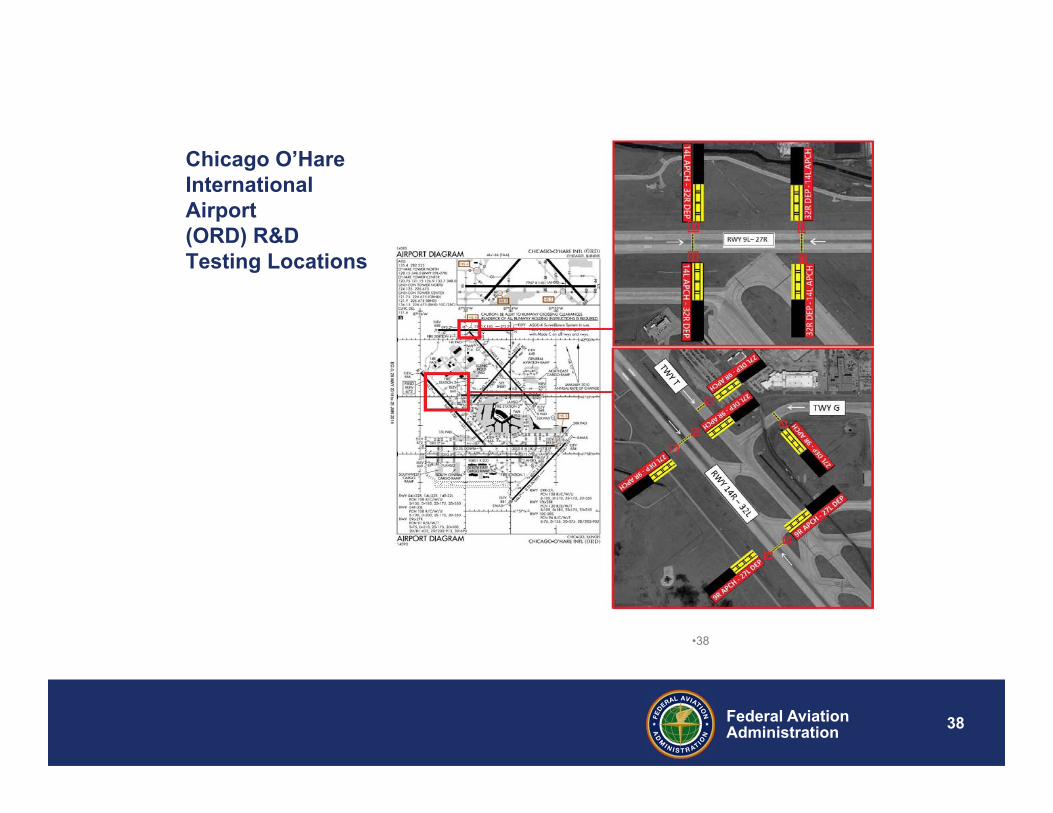
Chicago O’Hare International Airport(ORD) R&D Testing Locations
•38
39Federal AviationAdministration
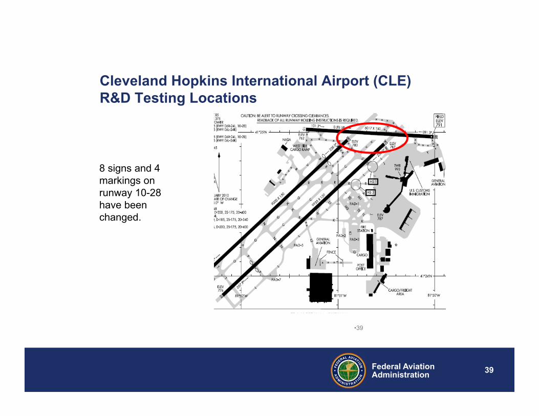
Cleveland Hopkins International Airport (CLE) R&D Testing Locations
8 signs and 4 markings on runway 10-28 have been changed.
•39
40Federal AviationAdministration
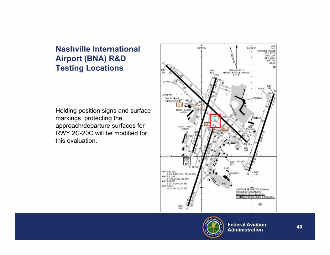
Nashville International Airport (BNA) R&D Testing Locations
Holding position signs and surface markings protecting the approach/departure surfaces for RWY 2C-20C will be modified for this evaluation.
40
41Federal AviationAdministration
•41
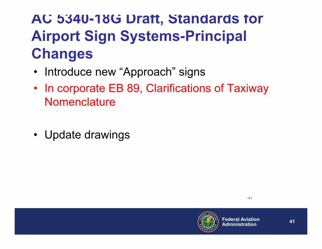
AC 5340-18G Draft, Standards for Airport Sign Systems-Principal Changes• Introduce new “Approach” signs• In corporate EB 89, Clarifications of Taxiway
Nomenclature
• Update drawings
42Federal AviationAdministration
•4242
43Federal AviationAdministration
A 1
B 1
B 8
C 1 J C 2
B 2
A 2 A 3
B 3
A 4
B 4
C 4
A 6 A 7
C 5
B 1 2
B 7 B 6
B 1 1 J
J
J
J
J
B 9
A 5
B 5
C 3
B 1 0
H IG H T R A F F ICC R O S S IN GT A X IW A Y S
L O W / M E D IU M T R A F F ICC R O S S IN GT A X IW A Y S
A
B
C
A
B
C
A
B
C
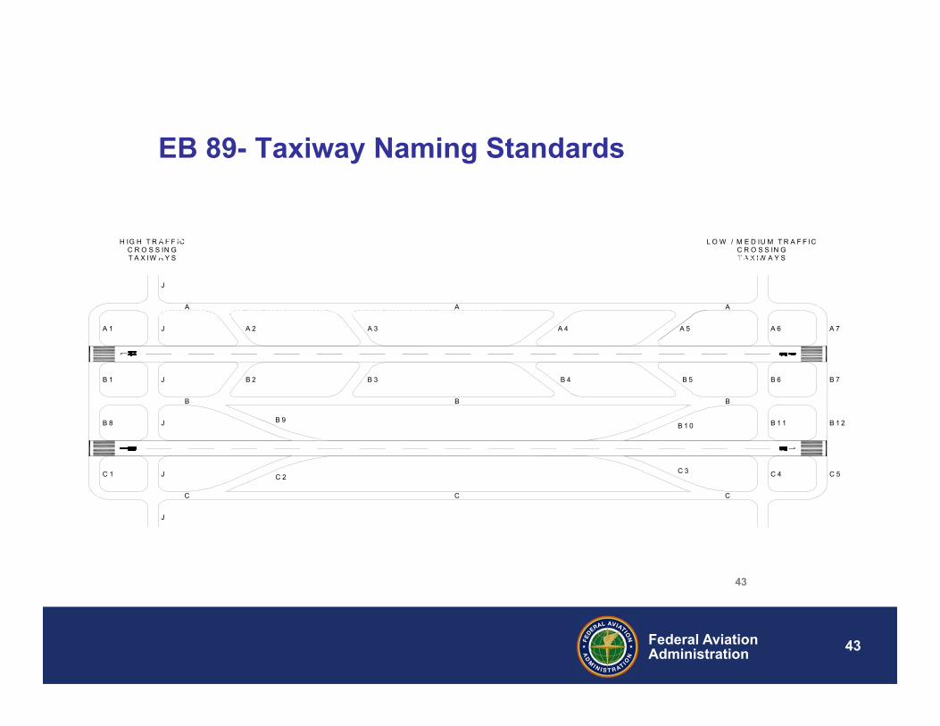
•c. A single alphabet letter (for example, A, B…, Z) must be utilized first for designating taxiways. Note that parallel taxiways to a runway must use single alphabet designations. For the purpose of this EB, a parallel taxiway is defined as a taxiway parallel to a runway that is either the full length or a partial length of the runway. • (1) Numbers by themselves, and the letters "I" and "O" must not be used because they could be mistaken for a runway number. • (2) The letter "X" must not be used because a sign with an "X" could be misconstrued as indicating a closed taxiway or runway.
EB 89- Taxiway Naming Standards
43
44Federal AviationAdministration
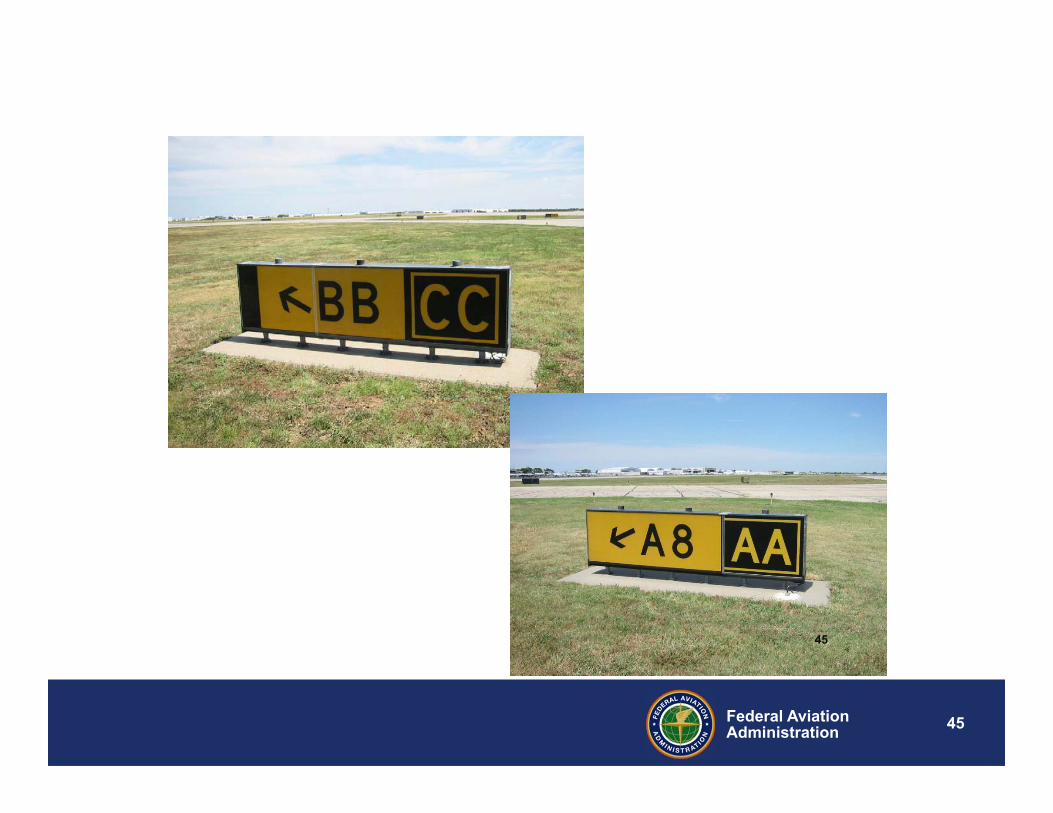
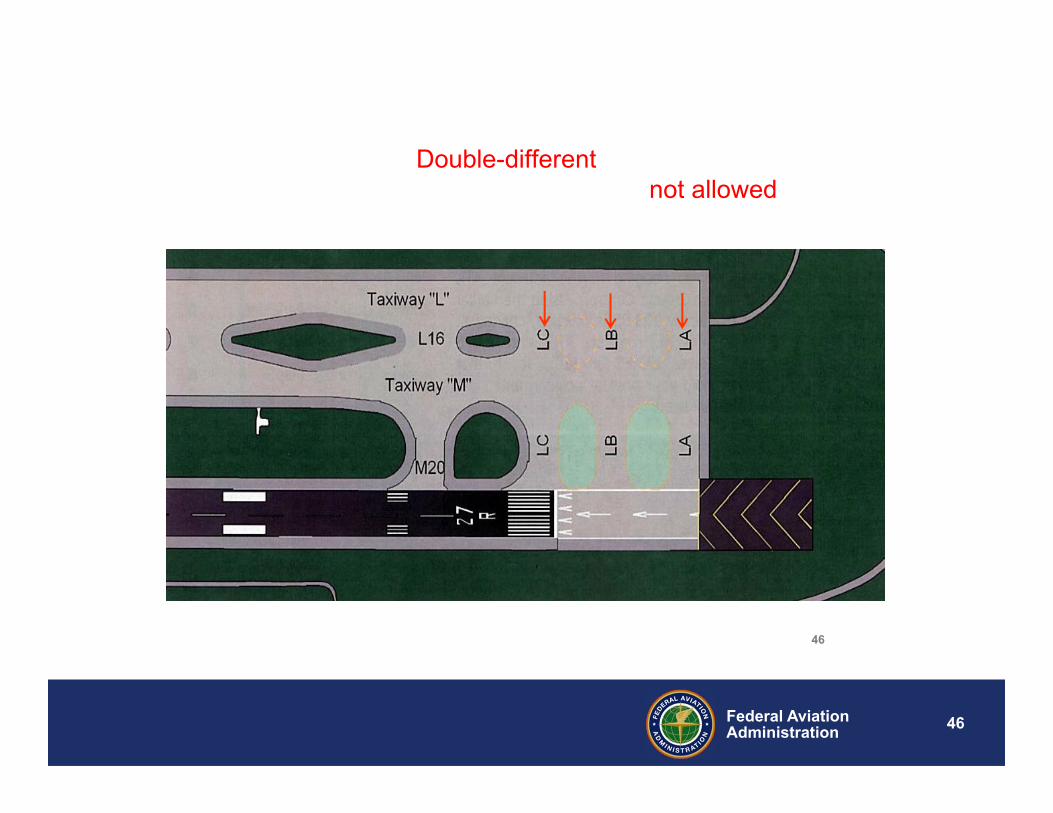
d. After all available single alphabet letters have been utilized, then designate taxiways with double-same alphabet letters (for example, AA, BB, …, ZZ). Double-different alphabet letters (e.g., AB, CD,…. ZW) taxiway designations are not allowed.
EB 89- Taxiway Naming Standards
44
45Federal AviationAdministration
45
46Federal AviationAdministration
Per paragraph d:.….Double-different alphabet letters (e.g., AB,CD,…. ZW) taxiway designations are not allowed.
46
47Federal AviationAdministration
A 1
B 1
B 8
C 1 J C 2
B 2
A 2 A 3
B 3
A 4
B 4
C 4
A6 A 7
C 5
B 12
B 7 B6
B11 J
J
J
J
J
B9
A 5
B5
C 3
B 10
H IG H TR A FFICC R O S S IN GTA X IW A Y S
LO W / M E D IU M TR A FFICC R O SS IN GTA XIW A Y S
A
B
C
A
B
C
A
B
C
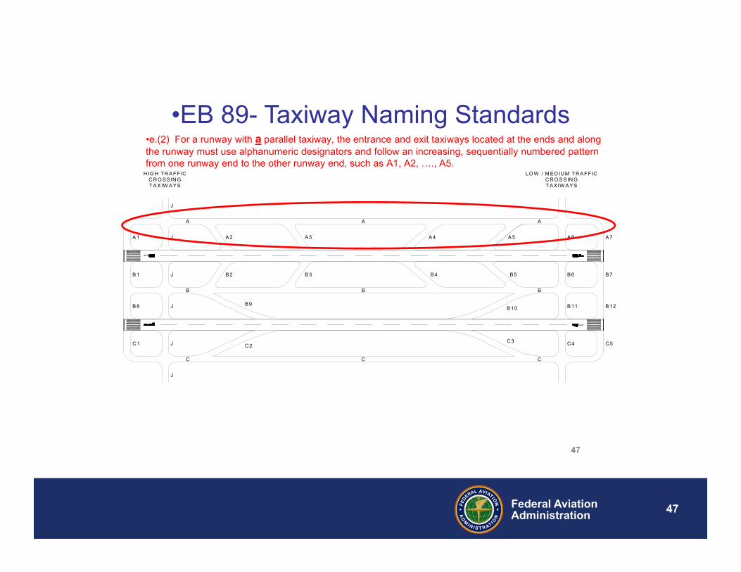
•e.(2) For a runway with a parallel taxiway, the entrance and exit taxiways located at the ends and along the runway must use alphanumeric designators and follow an increasing, sequentially numbered pattern from one runway end to the other runway end, such as A1, A2, …., A5.
•EB 89- Taxiway Naming Standards
47
48Federal AviationAdministration
A 1
B 1
B 8
C 1 J C 2
B 2
A 2 A 3
B 3
A 4
B 4
C 4
A 6 A 7
C 5
B 12
B 7 B 6
B 11 J
J
J
J
J
B 9
A 5
B 5
C 3
B 10
H IG H TR A FFICC R O S S IN GTA X IW A Y S
LO W / M E D IU M TR A FFICC R O S S IN GTA X IW A Y S
A
B
C
A
B
C
A
B
C
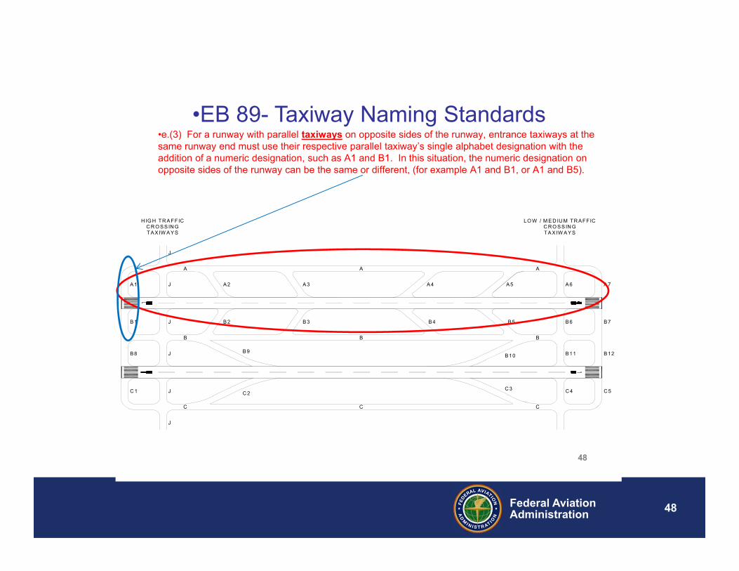
•e.(3) For a runway with parallel taxiways on opposite sides of the runway, entrance taxiways at the same runway end must use their respective parallel taxiway’s single alphabet designation with the addition of a numeric designation, such as A1 and B1. In this situation, the numeric designation on opposite sides of the runway can be the same or different, (for example A1 and B1, or A1 and B5).
•EB 89- Taxiway Naming Standards
48
49Federal AviationAdministration
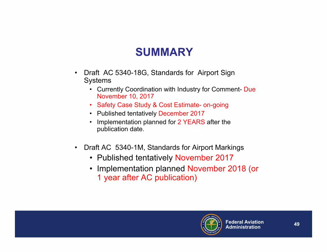
SUMMARY• Draft AC 5340-18G, Standards for Airport Sign
Systems • Currently Coordination with Industry for Comment- Due
November 10, 2017• Safety Case Study & Cost Estimate- on-going• Published tentatively December 2017 • Implementation planned for 2 YEARS after the
publication date.
• Draft AC 5340-1M, Standards for Airport Markings• Published tentatively November 2017• Implementation planned November 2018 (or
1 year after AC publication)
50Federal AviationAdministration
Q & A
51Federal AviationAdministration
THANK YOU!


![AIRPORT STANDARDS DIRECTIVE 502 [ASD 502] - Department of Civil Aviation Malaysia€¦ · · 2016-04-29AIRPORT STANDARDS DIRECTIVE 502 [ASD 502] VISUAL AIDS FOR NAVIGATION -](https://img.dokumen.tips/doc/110x75/5ad4ff707f8b9aff228c8ff7/airport-standards-directive-502-asd-502-department-of-civil-aviation-2016-04-29airport.jpg)