Embed Size (px)
Citation preview

FeaturesSmooth Lining for Walls and CeilingsImmune to Permanent Moisture DamageApplications:Internal Drywall (Wet Area System, Sound Rated System, Fire-Rated System)
A premium quality �bre cement board with square rebated edges for �ush jointed internal walls.
The continuous quest for better value for money and improvement are very common objectives. Now you have the comfort of knowing that the you have chosen will provide the on-going high performance and durability requirements.
is a high quality, high impact, �re resistant, �bre cement lining board ideal for walls in both domestic and commercial construction.
liner
Note: Where values are stated at EMC, the Ambient Temperature is 27° C± 2° C and Relative Humidity is between 65% - 95%.
Material & Application Speci�cations
Product Bene�ts• Immune to Permanent Moisture Damage
• High Impact Strength
• Termite Resistant
• Fire Resistant
• Climate-Friendly
• Good Sound Insulation
Material Properties & Composition
Sizes (mm) 1220mm x 2440mm Thickness (mm) 6 9 12 Mass per sheet (kg) 25.22 37.23 51.19 Sound Transmission Loss (dB) 25 28 30
Application Requirements/ Thickness 6mm 9mm 12mm Ceiling Lining • • • Wall Lining • • • Fire-Rated Wall • • •
Properties
EMC=1390kg/m³
Approximately 7%
0.06%
0.30W/mK
6.0mm - 0.030 m2 K/W
9.0mm - 0.045 m2 K/W
14 MPa Dry
8 MPa Wet
Class O (BS 476: Part 6 and BS 476: Part 7)
Values• Top Grade Cellulose Fibre• Finely Ground Sand• Portland Cement• Water
Product Composition
Nominal Density Moisture Movement at EMC Moisture Movement (from EMC to saturated) Thermal Conductivity, k Value Thermal Insulation, R Value
Flexural Strength at EMC
Fire Resistant
liner™
liner™

The table stipulates the minimum framing requirement. It is a good building practice to provide equal support spacing not exceeding the recommended centre distance to suit the sheet size. In all cases sheet edges must be supported.
Timber framing should be thoroughly selected and dried to minimize shrinkage when boards are installed. Steel frame thickness should be 0.50mm base metal thickness (BMT) to 1.55mm BMT.
** Please refer to HCI technical department for further detail.
Stud/ joist spacing Nogging spacing Support face width:
Note:
1. Screw fixing is only suitable for 6mm thick board and above.2. Screw head must be embedded 0.5mm below board surface.3. Nails and screw must be suitable coated for the intended applications
All nails shall comply with ‘AS 2334: 1980 - STEEL NAILS - METRIC SERIES’ or equivalent standard.
All screws shall comply with ‘AS 3566: 1988; SCREWS - SELF DRILLING - FOR THE BUILDING AND CONSTRUCTION INDUSTRIES’ or equivalent standard.
Vertical Sheet Fixing - Figure L2
12mm min.
610mm max. stud c/c
200mm c/c max.
1220mmc/c max.
50mmfromcorner
Top track
Bottom Track
6mm gap to �oor
Studs
Noggings
Horizontal Sheet Fixing = Figure L1
laid in staggered or brick pattern
12mm min.
12mm min.
610mm max. stud c/c
200mm c/c max.
200mm c/c max.
1220mm c/c max.
Bottom Track
6mm gap to �oor50mm from corner
Studs
Noggings
Table below show the suitable type of the fastener on the right framing:
Self-Embedding HeadSelf-Drilling Screw
Galvanised Steel Framing(0.5mm to 1.15mm thick)
Fixing to Steel Support(0.50 – 0.75) mm BMT - Screw with no Wingteks(0.75 – 1.15) mm BMT - Screw with Wingteks
Self-Embedding head,Self-Drilling and reamer point screws (for �xing to light gauge steel frame)
• 8 gauge - #18 x 25mm long to �x 6mm board • 8 gauge - #18 x 30mm long to �x 9mm board & 12mm board
Fixing to Timber Support
Galvanised Fibre Cement Nails(for �xing to softwood and hardwood)
• 2.8mm ø x 30mm for softwood • 2.0mm ø x 25mm for hardwood
Framing & Fixing Speci�cations
sheets must be �xed horizontally (Figure L1) or vertically (Figure L2), ensuring the vertical sheet joint on one side of the stud does not coincide with the vertical sheet joint on the other side to further enhance the stability of the wall.
Flush Joint Wall Applications
Support Framing Centre Distance (mm)
Framing Requirement
Table 2: Fastener Fixing Distance
Fastener Fixing DistanceFor Untiled Wall
12mm minimum from edges
50mm minimum from corners
200mm centres spacing along edges
300mm centres spacing elsewhere
Fastener Fixing Distance For Tiled Wall & Fire Rated Wall
12mm minimum from edges
50mm minimum from corners
200mm centres spacing along edges
200mm centres spacing elsewhere
610mm maximum
1220mm maximum
50mm minimum (timber)
36mm minimum (steel)
12mm12mm
Table 1: Fastener Speci�cations
Note: sheets must be fixed with a clearrance gap of 6mm from ground floor surface.
Fasterner Fixing Detail Figure
may be �xed to either timber or steel framing. The fasterner speci�cations and �xing distance shall be in accordance with Table T1 & T2.liner™
liner™
liner™
liner™
liner™
liner™

Flush Joint Ceiling Applications
3. Fastener Fixing DistancePlace fasteners 12mm from board edges and 50mm from corners. Fasteners must be spaced maximum 300mm centres at the board perimeter and intermediate framing.
1. Installation Speci�cation
Figure 1: Typical Ceiling Layout
2. Board InstallationBoard shall be in staggered pattern arrangement Figure: 2a DETAIL ’C’
12mm min
50mm min
FJC Cellulose Fibre Cement Board1220mm x 2440mm x 6mm(Available in 2, 3 or 4 sided rebated edges)
1220mm
Ceiling Screw
Detail ‘C’
Figure: 2
34mm x 12mm x 0.35mm Light Gauge Galvanised Steel Side Ceiling Batten @ 50mm max end to end
FJC Cellulose Fibre Cement Board1220mm x 1830mm x 4.5mm to be laid parallel to ceiling batten direction
34mm x 12mm x 0.35mm Light Gauge Galvanised Steel Support Batten @ 900mm max centers
34mm x 12mm x 0.35mm Light Gauge Galvanised Steel Middle Ceiling Batten @ 407mm centers
34mm x 12mm x 0.35mm Light Gauge Galvanised Steel Cross Rail @ 900mm max centers
407407
407
1220
900 max
Board Joint
100mm max
55mm max
900 max
50mm max
Support batten so�t of slabor �xed to roof truss
34mm x 12mm x 0.35mm Light Gauge Galvanised Steel SupportBatten @ 900mm max centers
34mm x 12mm x 0.35mm Light Gauge Galvanised SteelCeiling Batten @ 407mm centers
Wall
34mm x 12mm x 0.35mm Cross Rail @ 900mm max centers
FJC Cellulose Fibre Cement Board1220mm x 1830mm x 4.5mm
50mm max
Figure 1a: A’ - A’ Section Detail Figure 1b: B’ - B’ Section Detail
50mm max
34mm x 12mm x 0.35mm Light Gauge Galvanised Steel
Ceiling Batten @ 407mm centers
34mm x 12mm x 0.35mmLight Gauge Galvanised Steel
Support Batten @ 900mm max centers
34mm x 12mm x 0.35mmLight Gauge Galvanised Steel
Cross Rail @ 900mm max centers
Wall
liner™
liner™
liner™

4. Flush Joint DetailBoard joint can be treated by incorporating the Perforated Paper Jointing Tape and Gypsum Joint Compound. Best result can be achieved when both board edges have recesses. If it becomes necessary to �ush set over no recessed edges, the Bedding Layer, First Coat and Finishing Coat should be broadened to �ll the joined 200mm and 300mm respectively. Lightly sand the Board Joint when dry to get a smooth �nish before painting.
Figure 4: Access Panel Detail
2. Perforated Paper Jointing Tape embeded into Bedding Coat of Joint Compound
1. Bedding Coat:Joint Compound Bedding Layer to in�ll gap approximately 60mm wide
3. Topping Coat:Joint Compound Topping Layer approximately 200mm wide
4. Finishing Coat:Joint Compound Finishing Layer sanded to �nish approximately 270mm wide
5. Wall Finish with water-based Acrylic Paint
5. PaintingAfter the sanding process, the board must be painted with a minimum of 2 layers water-based Arcylic Paint. Make sure the board surface is in smooth condition and free from dust or any contaminant.
6. Access Panel DetailTwo sizes are available: 300mm x 300mm and 450mm x 450mm. (Please refer to HCI for further information.)
7. Expansion Joint DetailExpansion Joint should be provided at every 9000mm c/c formed using Heels with square cut edges. Provide an approximately 6mm wide gap between sheets and seal with paintable �exible Sealant. Do not apply Jointing Compound at the expansion joint.
Finishing Layer- (Approximately 300mm wide)
Fibre GlassJointing Tape
34mm x 12mm x 0.35mmLight Gauge Galvanised Steel Ceiling Batten @ 407mm max centres
Bedding Layer- Fill the joined recess areawith thin layer of Joint Compound
First Coat (Approximately 200mm wide)- Jointing Tape embedded in Joint Compound
FJC CelluloseFibre Cement Board
Figure 3: Flush Joint Detail
Figure 5: Expansion Joint Detail34mm x 12mm x 0.35mmLight Gauge Galvanised Steel CrossRail at 900mm max centres
34mm x 12mm x 0.35mmLight Gauge Galvanised Steel Ceiling
Bettern at 407mm max centres
34mm x 12mm x 0.35mm LightGauge Galvanised Steel Hanger at900mm max centres
1220mm x 1830mm x 4.5mm FJC Cellulose Fibre Cement Board
Expansion Joint Kit
liner™
liner™
liner™
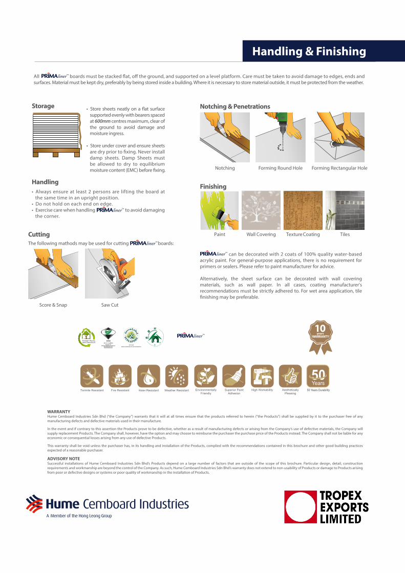
Cutting
Notching & Penetrations
Score & Snap
Notching Forming Round Hole Forming Rectangular Hole
Saw Cut
can be decorated with 2 coats of 100% quality water-based acrylic paint. For general-purpose applications, there is no requirement for primers or sealers. Please refer to paint manufacturer for advice.
Alternatively, the sheet surface can be decorated with wall covering materials, such as wall paper. In all cases, coating manufacturer's recommendations must be strictly adhered to. For wet area application, tile �nishing may be preferable.
Paint Wall Covering Texture Coating Tiles
Finishing
Storage
• Always ensure at least 2 persons are lifting the board at the same time in an upright position.
• Do not hold on each end on edge.• Exercise care when handling to avoid damaging
the corner.
Handling & Finishing
Handling
The following mathods may be used for cutting boards:
All boards must be stacked �at, o� the ground, and supported on a level platform. Care must be taken to avoid damage to edges, ends and surfaces. Material must be kept dry, preferably by being stored inside a building. Where it is necessary to store material outside, it must be protected from the weather.
liner™
liner™
• Store sheets neatly on a �at surface supported evenly with bearers spaced at 600mm centres maximum, clear of the ground to avoid damage and moisture ingress.
• Store under cover and ensure sheets are dry prior to �xing. Never install damp sheets. Damp Sheets must be allowed to dry to equilibrium moisture content (EMC) before �xing.
10WARRANTY
years
WARRANTYHume Cemboard Industries Sdn Bhd (“the Company”) warrants that it will at all times ensure that the products referred to herein (“the Products”) shall be supplied by it to the purchaser free of any manufacturing defects and defective materials used in their manufacture.
In the event and if contrary to this assertion the Products prove to be defective, whether as a result of manufacturing defects or arising from the Company’s use of defective materials, the Company will supply replacement Products. The Company shall, however, have the option and may choose to reimburse the purchaser the purchase price of the Products instead. The Company shall not be liable for any economic or consequential losses arising from any use of defective Products.
This warranty shall be void unless the purchaser has, in its handling and installation of the Products, complied with the recommendations contained in this brochure and other good building practices expected of a reasonable purchaser.
ADVISORY NOTESuccessful installations of Hume Cemboard Industries Sdn Bhd’s Products depend on a large number of factors that are outside of the scope of this brochure. Particular design, detail, construction requirements and workmanship are beyond the control of the Company. As such, Hume Cemboard Industries Sdn Bhd’s warranty does not extend to non-usability of Products or damage to Products arising from poor or defective designs or systems or poor quality of workmanship in the installation of Products.
liner™
liner™
liner™