Embed Size (px)
Citation preview

Chrysl Assumpta Aranha
Feasibility Study of Textile Reinforced Shotcrete for Strengthening Unreinforced Masonry Structures
Czech Technical University in Prague

Chrysl Assumpta Aranha
Feasibility Study of Textile Reinforced Shotcrete for Strengthening Unreinforced Masonry Structures
Spain │ 2012

Feasibility Study of Textile Reinforced Shotcrete for Unreinforced Masonry Structures
Erasmus Mundus Programme ADVANCED MASTERS IN STRUCTURAL ANALYSIS OF MONUMENTS AND HISTORICAL CONSTRUCTIONS I
DECLARATION
Name: Chrysl Assumpta Aranha
Email: [email protected]
Title of the
Msc Dissertation:
Feasibility Study of Textile Reinforced Shotcrete for Strengthening
Unreinforced Masonry Structures
Supervisors: Dr. Lluis Gil
Mr. Ernest Bernat
Year: 2011/2012
I hereby declare that all information in this document has been obtained and presented in accordance
with academic rules and ethical conduct. I also declare that, as required by these rules and conduct, I
have fully cited and referenced all material and results that are not original to this work.
I hereby declare that the MSc Consortium responsible for the Advanced Masters in Structural Analysis
of Monuments and Historical Constructions is allowed to store and make available electronically the
present MSc Dissertation.
University: Technical University of Catalonia, Spain
Date: 16-07-2012
Signature: ___________________________

Feasibility Study of Textile Reinforced Shotcrete for Unreinforced Masonry Structures
Erasmus Mundus Programme II ADVANCED MASTERS IN STRUCTURAL ANALYSIS OF MONUMENTS AND HISTORICAL CONSTRUCTIONS

Feasibility Study of Textile Reinforced Shotcrete for Unreinforced Masonry Structures
Erasmus Mundus Programme ADVANCED MASTERS IN STRUCTURAL ANALYSIS OF MONUMENTS AND HISTORICAL CONSTRUCTIONS III
DEDICATION
I dedicate this thesis to my mother – for everything that she has done for me.

Feasibility Study of Textile Reinforced Shotcrete for Unreinforced Masonry Structures
Erasmus Mundus Programme IV ADVANCED MASTERS IN STRUCTURAL ANALYSIS OF MONUMENTS AND HISTORICAL CONSTRUCTIONS

Feasibility Study of Textile Reinforced Shotcrete for Unreinforced Masonry Structures
Erasmus Mundus Programme ADVANCED MASTERS IN STRUCTURAL ANALYSIS OF MONUMENTS AND HISTORICAL CONSTRUCTIONS V
ACKNOWLEDGEMENTS
On the completion of my thesis, I would like to express my sincere thanks to the following people-
-Prof. Lluis Gil, my thesis supervisor, who gave me the opportunity to work under his guidance in the
field of my interest.
-Mr. Ernest Bernat, for all the help and directions he gave me.
- Mr. Vicenç for setting up the equipment in the laboratory and making the necessary arrangements for
my experimental work and Mr. Christian Escrig for helping me to understand the subject better by
letting me be a part of his research work.
-The entire staff at LITEM at Terrassa for making me comfortable at my workplace.
- Prof. Pere Roca, for always answering queries and making necessary arrangements during our stay
at the UPC.
-The concerned faculty of the Czech Technical University in Prague and the Technical University of
Catalonia in Barcelona, for organizing informative and wonderful field trips.
-The SAHC consortium for selecting me for this Program.
I especially thank my classmates in the program who made the learning experience a whole lot more
enjoyable.
and most importantly, my parents and sisters, without whose support and encouragement I would
never have come this far.
This has truly been one of the most amazing experiences in my life.

Feasibility Study of Textile Reinforced Shotcrete for Unreinforced Masonry Structures
Erasmus Mundus Programme VI ADVANCED MASTERS IN STRUCTURAL ANALYSIS OF MONUMENTS AND HISTORICAL CONSTRUCTIONS

Feasibility Study of Textile Reinforced Shotcrete for Unreinforced Masonry Structures
Erasmus Mundus Programme ADVANCED MASTERS IN STRUCTURAL ANALYSIS OF MONUMENTS AND HISTORICAL CONSTRUCTIONS VII
ABSTRACT
The Textile Reinforced Mortar system that has been developed recently is based on introducing a
textile fabric which could be a carbon fibre, glass fibre, vegetal fibre,etc. embedded in a superficial
layer of modified mortar. The technique of manual application of textile reinforcement embedded in a
cementitious mortar has been explored and its efficiency in strengthening masonry and concrete
members in flexure, compression and shear has been established. However, this process is time-
consuming and labour-intensive. This becomes an issue especially when huge walls and large
sections of a building have to be strengthened. Hence, the study of how to industrialize its application
is the next logical step in the developing path of this system. With this in mind, the feasibility of
pumping a micro-concrete and projecting it onto vertical surfaces of unreinforced masonry (URM) was
analyzed. This kind of technology, which is a mix between TRM and shotcrete can be termed as
Textile Reinforced Shotcrete (TRSc). It has been successfully employed in the strengthening of
reinforced concrete buildings. If successful in unreinforced masonry, it could result in cost reduction of
the TRM system. This in turn could open the market of strengthening larger structures in a competitive
timing.
For this thesis, the foreseen tasks to achieve the main objectives are: bibliographic research to
describe the state of the art, defining the necessary machinery and procedures to project the micro-
concrete in a suitable thickness, carrying out experimental tests of application and destructive tests to
validate the effectiveness of the TRSc strengthening.
In the present study, the structural behaviour of unreinforced masonry walls strengthened with textile
reinforcement placed in projected mortar is studied. The technique used to install the grids in air-
sprayed mortar was novel and the savings in time and quantity of mortar was evident. Ten specimens
were fabricated , out of which, most were tested by applying the mortar in a sprayed form and some of
them were strengthened by hand application of mortar. The specimens are subjected to three-point
bending tests to characterize their mechanical behaviour. The overall increase in the strength of the
TRSc reinforced specimens was compared with the ones reinforced with TRM. The studied
parameters also included the mesh size and type of the textile reinforcement, the number of sides
reinforced and the number of layers of reinforcement. A study was also made on the orientation and
properties of the textile grids and their effect on the system. From the results obtained in the study, it is
concluded that when used with reinforcement that has an optimum mesh size, TRSc strengthening for
unreinforced masonry structures is economical and can strengthen unreinforced masonry structures to
a higher degree than when TRM is used.
Keywords: Projected mortar, Textile reinforcement, unreinforced masonry, strengthening

Feasibility Study of Textile Reinforced Shotcrete for Unreinforced Masonry Structures
Erasmus Mundus Programme VIII ADVANCED MASTERS IN STRUCTURAL ANALYSIS OF MONUMENTS AND HISTORICAL CONSTRUCTIONS
RESUMO
(Estudi de viabilitat de l'ús de textils amb morters projectats per al reforç d'estructures de masoneria)
El sistema de reforç tèxtil amb morter TRM (Textile Reinforced Mortar) desenvolupat recentment es
basa en la introducció d'un producte tèxtil que pot ser una fibra de carboni, fibra de vidre, fibres
vegetals, etc embegut dins una capa superficial de morter modificat.
La tècnica d'aplicació manual de reforç tèxtil embegut en un morter de ciment ha estat explorada.
S’ha observat que augmenta l’eficiència en l'enfortiment de la maçoneria i el formigó. El reforç és
eficaç tant en la flexió, compressió com en el cisallament. No obstant això, aquest procés és lent i
laboriós. Això es converteix en un problema, sobretot quan s’han de reforçar grans superfícies de
paret i grans sectors d'un edifici. Per tant, l'estudi de la forma d'industrialitzar la seva aplicació és el
següent pas lògic en la trajectòria de desenvolupament d'aquest sistema. Tenint això present, la
possibilitat de bombament d'un micro-formigó i la seva projecció sobre superfícies verticals de
maçoneria no reforçada (URM) Unreinforced Masonry, es l’objecte d’aquest treball. Aquest tipus de
tecnologia, que és una barreja entre la TRM i el formigó projectat pot ser denominat com reforç tèxtil
amb formigó projectat Textile Reinforced Shotcrete (TRSC). Fins ara s'ha emprat amb èxit en el reforç
dels edificis de formigó armat. Si té èxit en la maçoneria no reforçada, pot representar la reducció de
costos del sistema de TRM. Això podria obrir el mercat de reforç de les estructures més grans en un
temps competitiu.
Per a aquesta tesi, les tasques previstes per assolir els objectius principals són: la recerca
bibliogràfica per descriure l'estat de la tècnica, la definició dels mecanismes i procediments necessaris
per projectar el micro-formigó amb un gruix adequat, la realització de proves experimentals d'aplicació
i proves destructives per validar l'eficàcia del reforç TRSC.
En l'experiment, les mostres consisteixen en prismes de maçoneria apilades amb nou maons
cadascun. Deu exemplars van ser fabricats, dels quals, set mostres van ser analitzades mitjançant
l'aplicació del morter en un aerosol i tres d'ells es van veure reforçades per l'aplicació manual de
morter. El temps necessari per instal · lar 10 capes de tèxtil amb la tècnica de polvorització era el
mateix que el necessari per instal · lar tres capes amb la mà. Els paràmetres estudiats inclouen també
la mida de malla i tipus del reforç tèxtil, el nombre de costats reforçat i el nombre de capes de reforç.
El programa experimental comprén una prova de flexió de tres punts i l'obtenció d'un gràfica de la
càrrega davant del desplaçament per a cada mostra. Es va trobar que, en general, les mostres
reforçades per l'aplicació manual de morter podien suportar una càrrega superior final que les que
havien estat polvoritzades pel morter. No obstant això, les mostres de fibra de vidre reforçades amb el
morter projectat es van comportar millor que les fabricades de forma manual per la formació
d’enllaços més forts entre els dos materials. Les malles tèxtils amb una mida de forat més gran es van
comportar millor que els seus equivalents amb una llum de malla menor ja que el morter va ser capaç
de penetrar millor en les primeres. Les mostres que van ser reforçades amb dues capes de reforç van

Feasibility Study of Textile Reinforced Shotcrete for Unreinforced Masonry Structures
Erasmus Mundus Programme ADVANCED MASTERS IN STRUCTURAL ANALYSIS OF MONUMENTS AND HISTORICAL CONSTRUCTIONS IX
mostrar un gran augment en la resistència, mentre que el que s'ha reforçat en els dos costats no té
cap efecte sobre el rendiment. Per causa de la seva elevada rigidesa, els espècimens reforçats amb
malles tèxtils de carboni han patit una mala adherència entre els materials. Les mostres reforçades
amb reixetes d'acer han estat les més fortes ja que les fibres funcionaven unidireccionalment. Els
espècimens reforçats amb malles de basalt van mostrar el comportament més dúctil. Quan la
grandària de la malla és gran, TRSC és una opció millor i més ràpida que el TRM per a les estructures
de URM.

Feasibility Study of Textile Reinforced Shotcrete for Unreinforced Masonry Structures
Erasmus Mundus Programme X ADVANCED MASTERS IN STRUCTURAL ANALYSIS OF MONUMENTS AND HISTORICAL CONSTRUCTIONS
RESUMEN
(Estudio de viabilidad del uso de textiles con mortero proyectado para el refuerzo de estructuras de masonerîa)
El sistema de refuerzo textil con mortero TRM (Textile Reinforced Mortar) desarrollado recientemente
se basa en la introducción de un producto textil que puede ser una fibra de carbono, fibra de vidrio,
fibras vegetales, etc embebido dentro de una capa superficial de mortero modificado.
La técnica de aplicación manual de refuerzo textil embebido en un mortero de cemento ha sido
explorada. Se ha observado que aumenta la eficiencia en el fortalecimiento de la masonería y el
hormigón. El refuerzo es eficaz tanto en la flexión, compresión como en el cizallamiento. Sin
embargo, este proceso es lento y laborioso. Esto se convierte en un problema, sobre todo cuando
deben reforzarse grandes superficies de pared y grandes sectores de un edificio. Por tanto, el estudio
de la forma de industrializar su aplicación es el siguiente paso lógico en la trayectoria de desarrollo de
este sistema. Con esto en mente, la posibilidad de bombeo de un micro-hormigón y su proyección
sobre superficies verticales de mampostería no reforzada (URM) Unreinforced Masonry, es el objeto
de este trabajo. Este tipo de tecnología, que es una mezcla entre la TRM y el hormigón proyectado
puede ser denominado como refuerzo textil con hormigón proyectado Textile Reinforced Shotcrete
(TRSC). Hasta ahora se ha empleado con éxito en el refuerzo de los edificios de hormigón armado. Si
tiene éxito en la masonería no reforzada, puede representar la reducción de costes del sistema de
TRM. Esto podría abrir el mercado de refuerzo de las estructuras más grandes en un tiempo
competitivo.
Para esta tesis, las tareas previstas para alcanzar los objetivos principales son: la investigación
bibliográfica para describir el estado de la técnica, la definición de los mecanismos y procedimientos
necesarios para proyectar el micro-hormigón con un espesor adecuado, la realización de pruebas
experimentales de aplicación y pruebas destructivas para validar la eficacia del refuerzo TRSc.
En el experimento, las muestras consisten en prismas de mampostería apiladas con nueve ladrillos
cada uno. Diez ejemplares fueron fabricados, de los cuales, siete muestras fueron analizadas
mediante la aplicación del mortero en un aerosol y tres de ellos se vieron reforzadas por la aplicación
manual de mortero. El tiempo necesario para instalar 10 capas de textil con la técnica de
pulverización era el mismo que el necesario para instalar tres capas con la mano. Los parámetros
estudiados incluyen también el tamaño de malla y tipo del refuerzo textil, el número de lados
reforzado y el número de capas de refuerzo. El programa experimental comprende una prueba de
flexión de tres puntos y la obtención de un gráfica de la carga ante el desplazamiento para cada
muestra. Se encontró que, en general, las muestras reforzadas por la aplicación manual de mortero
podían soportar una carga superior final que las que habían sido pulverizadas por el mortero. Sin
embargo, las muestras de fibra de vidrio reforzadas con el mortero proyectado se comportaron mejor

Feasibility Study of Textile Reinforced Shotcrete for Unreinforced Masonry Structures
Erasmus Mundus Programme ADVANCED MASTERS IN STRUCTURAL ANALYSIS OF MONUMENTS AND HISTORICAL CONSTRUCTIONS XI
que las fabricadas de forma manual para la formación de enlaces más fuertes entre los dos
materiales. Las mallas textiles con un tamaño de agujero más grande se comportaron mejor que sus
equivalentes con una luz de malla menor ya que el mortero fue capaz de penetrar mejor en las
primeras. Las muestras que fueron reforzadas con dos capas de refuerzo mostraron un gran aumento
en la resistencia, mientras que el que se ha reforzado en los dos lados no tiene ningún efecto sobre el
rendimiento. Por causa de su elevada rigidez, los especímenes reforzados con mallas textiles de
carbono han sufrido una mala adherencia entre los materiales. Las muestras reforzadas con rejillas
de acero han sido las más fuertes ya que las fibras funcionaban unidireccionalmente. Los
especímenes reforzados con mallas de basalto mostraron el comportamiento más dúctil. Cuando el
tamaño de la malla es grande, TRSc es una opción mejor y más rápida que el TRM para las
estructuras de URM.

Feasibility Study of Textile Reinforced Shotcrete for Unreinforced Masonry Structures
Erasmus Mundus Programme XII ADVANCED MASTERS IN STRUCTURAL ANALYSIS OF MONUMENTS AND HISTORICAL CONSTRUCTIONS
TABLE OF CONTENTS
1.INTRODUCTION ................................................................................................................ 1 1.1 CONVENTIONAL STRENGTHENING METHODS..................................................................... 1
1.1.1 Overlays ............................................................................................................................. 1 1.1.1.1 Ferrocement................................................................................................................ 1 1.1.1.2 Shotcrete..................................................................................................................... 2 1.1.1.3 Reinforced plaster....................................................................................................... 3
1.1.2 Prestressing ....................................................................................................................... 3 1.1.3 Repointing .......................................................................................................................... 4 1.1.4 Crack Stitching and Grouting/Epoxy Injection...................................................................... 5 1.1.5 External Reinforcement ...................................................................................................... 6 1.1.6 Confinement ....................................................................................................................... 7 1.1.7 Centre Core Method ........................................................................................................... 7
1.2 MOTIVATION ............................................................................................................................ 8 1.3 RESEARCH SIGNIFICANCE .................................................................................................. 11 1.4 OBJECTIVES OF THE THESIS............................................................................................... 11 1.5 THESIS OUTLINE ................................................................................................................... 12
2. LITERATURE REVIEW ................................................................................................... 13
2.1 TEXTILE REINFORCED MORTARS FOR CONCRETE .......................................................... 13 2.2 TEXTILE REINFORCED MORTARS FOR UNREINFORCED MASONRY ............................... 18 2.3 TEXTILE REINFORCED SHOTCRETE FOR REINFORCED CONCRETE SUBSTRATES ...... 22
3. PROPERTIES OF MATERIALS USED............................................................................ 25
3.1 BRICKS ................................................................................................................................. 25 3.2 MORTAR USED FOR JOINTS ................................................................................................ 26 3.3 MORTAR USED FOR OVERLAY ............................................................................................ 26 3.4 TEXTILE GRIDS ..................................................................................................................... 29
3.4.1 Basalt grids ...................................................................................................................... 29 3.4.2 Glass grids ....................................................................................................................... 30 3.4.3 Steel grids ........................................................................................................................ 30 3.4.4 Carbon grids ..................................................................................................................... 31
4. EXPERIMENTAL PROCEDURE ..................................................................................... 33
4.1 FABRICATION OF SPECIMENS ............................................................................................. 33 4.2 MEASURING THE DIMENSIONS ........................................................................................... 36 4.3 SETTING UP THE UNREINFORCED SPECIMENS IN THE LITEM LABORATORY ................ 37 4.2 DESIGNATION OF SPECIMENS ............................................................................................ 38 4.3 APPLICATION OF TEXTILE REINFORCEMENT .................................................................... 39
4.3.1 Shotcrete Application ........................................................................................................ 39 4.3.1.1 Fixing the textile reinforcement................................................................................ 40 4.3.1.1 Wetting the surface of the specimens ...................................................................... 41 4.3.1.1 The pumping equipment ......................................................................................... 42 4.3.1.1 The shotcrete process ............................................................................................ 44

Feasibility Study of Textile Reinforced Shotcrete for Unreinforced Masonry Structures
Erasmus Mundus Programme ADVANCED MASTERS IN STRUCTURAL ANALYSIS OF MONUMENTS AND HISTORICAL CONSTRUCTIONS XIII
4.3.2 Manual Application ........................................................................................................... 49 4.3.2.1 Wetting the surface of the specimens ...................................................................... 49 4.3.2.2 Application of TRM .................................................................................................. 49
5. TESTING OF STRENGTHENED SPECIMENS ............................................................... 52
5.1 THREE POINT BENDING TEST.............................................................................................. 52 5.2 MODES OF FAILURE ............................................................................................................. 54
6. DISCUSSION AND CONCLUSION ................................................................................. 70
6.1 ANALYSIS OF THE RESULTS AND CONCLUSION ............................................................... 70 6.2 DRAWBACKS OF THE SPRAYING TECHNIQUE ................................................................... 73 6.3 SCOPE FOR FUTURE RESEARCH ........................................................................................ 75
7. REFERENCES ................................................................................................................ 77

Feasibility Study of Textile Reinforced Shotcrete for Unreinforced Masonry Structures
Erasmus Mundus Programme XIV ADVANCED MASTERS IN STRUCTURAL ANALYSIS OF MONUMENTS AND HISTORICAL CONSTRUCTIONS
LIST OF FIGURES
Figure 1 Hardware samples used in ferrocement (ElGawady, Lestuzzi, & Badoux, 2004) .................. 2
Figure 2 Application of shotcrete (ElGawady, Lestuzzi, & Badoux, 2006) ............................................ 2
Figure 3 Reinforced plaster overlay showing typical dimensions (WHE Report 73, Slovenia) .............. 3
Figure 4 An example of a post tensioned retrofitted masonry system
(http://www.cintec.com/blastec/structure-reinforcement.php) ............................................................... 4
Figure 5 Examples of repointing (left) and deep repointing (right) masonry (Drdacky & Valek, 2011) ... 4
Figure 6 Crack stitching technique (Drdacky & Valek, 2011) ............................................................... 5
Figure 7 Grouting techniques (Ashurst & Ashurst, 1998) ..................................................................... 6
Figure 8 Wall having vertical and diagonal bracing (Taghdi, Bruneau, & Saatcioglu, 2000) ................. 6
Figure 9 Placing new tie columns in an existing brick masonry wall (ElGawady, Lestuzzi, & Badoux,
2004) .................................................................................................................................................. 7
Figure 10 Centre core method of strengthening (SAHC lecture notes –Drdacky,Valek,Biggs) ............. 8
Figure 11 Components of the FRP system ......................................................................................... 8
Figure 12 Illustrative examples of fibre reinforcement sheets and textile reinforcement grids............... 9
Figure 13 Model of strengthened concrete beam used in Curbach's experiment ............................... 13
Figure 14 Plot of load versus deflection obtained from Curbach's experiments (Wiberg, 2003) .......... 14
Figure 15 Model of concrete beams used in Kolsch’ experiments ..................................................... 14
Figure 16 Plot of load versus deflection for various combinations obtained from Kolsch's experiments
(Wiberg, 2003) .................................................................................................................................. 15
Figure 17 Positions of application of TRM on the concrete beam ...................................................... 15
Figure 18 Mixing the mortar to be applied on the concrete beams .................................................... 16
Figure 19 Application of water(left side) and the first layer of mortar (right side) respectively ............. 16
Figure 20 Placing the textile grid and trowelling it in the mortar...........................................................17
Figure 21 Installing the grids across the beam for better bonding of TRM on main span.................... 17
Figure 22 Final appearance of the strengthened beam ..................................................................... 18
Figure 23 Specimens used in out-of-plane tests performed by Papanicolau et al. ............................. 19
Figure 24 Process of manual application of TRM (Papanicolaou, Triantafillou and Lekka 2011) ........ 19
Figure 25 Three point bending test (Papanicolaou, Triantafillou and Lekka 2011) ............................. 20
Figure 26 Loading set-up and reinforcement details of the masonry specimens (Harajli, El Khatib and
San-Jose 2010) ................................................................................................................................ 21
Figure 27 Multi-axial and bi-axial textiles used in the experiments performed by Munich et al. .......... 22
Figure 28 Reinforcing the reinforced concrete annular vault with TRSc (Hankers & Matzdorff) ......... 23
Figure 29 TRSc application for the office building in Prague (Hankers & Matzdorff) .......................... 23
Figure 30 Dimensions of the masonry units ...................................................................................... 25
Figure 31 Moulds for the mortar specimens ...................................................................................... 27
Figure 32 Flexure test schematic(left), lab set-up (centre) and specimen failure mode (right) .. 27Error! Bookmark not defined.

Feasibility Study of Textile Reinforced Shotcrete for Unreinforced Masonry Structures
Erasmus Mundus Programme ADVANCED MASTERS IN STRUCTURAL ANALYSIS OF MONUMENTS AND HISTORICAL CONSTRUCTIONS XV
Figure 33 Graph of force versus displacement obtained from the flexural test of specimen no.2 ........28
Figure 34 Compression test set-up in the lab (left) and failure mode of the specimen (right) ..............28
Figure 35 Basalt mesh fibre reinforcement ........................................................................................29
Figure 36 Glass fibre reinforcement mesh ........................................................................................30
Figure 37 Steel fibre reinforcement mesh .........................................................................................31
Figure 38 Carbon fibre reinforcement mesh ......................................................................................31
Figure 39 Mixing of Mortar ................................................................................................................33
Figure 40 Bricks placed on wooden logs(left) and bricks immersed in water before use (right) ..........34
Figure 41 Laying of mortar on brick (left) and levelling (right) ............................................................34
Figure 42 Process of building specimens ..........................................................................................35
Figure 43 Scraping the surfaces to ensure smoothness ....................................................................35
Figure 44 Completed wall specimens ...............................................................................................36
Figure 45 Measuring the Width, Thickness and Length of the Specimens .........................................37
Figure 46 Transporting the Specimens into the Lab Using the Stacking Machine ..............................37
Figure 47 The Crane Used to Transfer the Specimens to the Location of Shotcreting .......................38
Figure 48 Nuts glued to the Textile Grids ..........................................................................................40
Figure 49 Front and side views of the textile grid attached to the masonry specimen ........................40
Figure 50 Specimens glued with textile grids ....................................................................................41
Figure 51 Wetting the specimens before shotcreting them ................................................................41
Figure 52 Mixer plus 380V ................................................................................................................43
Figure 53 Side(left) and front(right) views of the machine with relative dimensions ............................44
Figure 54 The shotcreting equipment connected to the water supply ................................................44
Figure 55 Introducing the projection mortar into the mixer .................................................................45
Figure 56 Nozzle position just before the mortar was sprayed onto the specimen .............................45
Figure 57 Spraying procedure of an individual specimen ..................................................................46
Figure 58 Sequence of air-spraying of fine-grained mortar on the specimens ....................................46
Figure 59 Positioning the second textile grid and trowelling it ............................................................47
Figure 60 The second layer of textiles which are lightly embedded in the mortar ...............................47
Figure 61 Spraying mortar on top of the second layer of reinforcement .............................................48
Figure 62 Shotcreted specimens ......................................................................................................48
Figure 63 Wetting the specimens before manual application of mortar ..............................................49
Figure 64 Applying the first layer of mortar ........................................................................................50
Figure 65 Inserting the textile grids ...................................................................................................50
Figure 66 Application of the second layer of mortar,over the grid ......................................................51
Figure 67 Trowelling the second layer of mortar................................................................................51
Figure 68 Smoothened surface of the specimen which has been strengthened manually ..................51
Figure 69 The specimen in transit to the test set-up ..........................................................................52
Figure 70 Side and front views of support details showing the elastomeric base ...............................53

Feasibility Study of Textile Reinforced Shotcrete for Unreinforced Masonry Structures
Erasmus Mundus Programme XVI ADVANCED MASTERS IN STRUCTURAL ANALYSIS OF MONUMENTS AND HISTORICAL CONSTRUCTIONS
Figure 71 Details of load application and potentiometer placement ................................................... 53
Figure 72 Overall test set up ............................................................................................................ 54
Figure 73 Expected failure modes from three point bending test ....................................................... 55
Figure 74 The split pieces of the first specimen ................................................................................ 55
Figure 75 Graph of load vs. displacement at mid-span for the first specimen .................................... 56
Figure 76 Cracking(left) and exposed grid due to fallen mortar(right) ................................................ 56
Figure 77 Shear failure between bricks on both sides ....................................................................... 57
Figure 78 Graph of load vs. displacement at mid-span for the second specimen ............................... 57
Figure 79 Specimen no. 3 at failure .................................................................................................. 58
Figure 80 Split pieces of specimen no. 3 after failure ........................................................................ 58
Figure 81 Graph of load vs. displacement at mid-span for the third specimen ................................... 59
Figure 82 Failure of the specimen due to tensile fracture of basalt fibres .......................................... 59
Figure 83 Graph of load vs. displacement at mid-span for the fourth specimen ................................. 60
Figure 84 Tensile failure of fibres in specimen reinforced with double-layered basalt grid .................. 60
Figure 85 Graph of load vs. displacement at mid-span for the fifth specimen .................................... 61
Figure 86 Initial cracking of the beam ............................................................................................... 61
Figure 87 Shearing process of the specimen .................................................................................... 62
Figure 88 Specimen no. 6 at failure .................................................................................................. 62
Figure 89 Graph of load vs. displacement at mid-span for the sixth specimen ................................... 63
Figure 90 Failure of specimen no. 7 by debonding of textile grid ....................................................... 63
Figure 91 Mortar layer just superficially attached to the textile grid with enlarged detail ..................... 64
Figure 92 Graph of load vs. displacement at mid-span for the seventh specimen .............................. 64
Figure 93 Formation of opening with stretching of fibres ................................................................... 65
Figure 94 Shear failure onset ........................................................................................................... 65
Figure 95 Broken specimen showing good bond between glass grid and mortar ............................... 66
Figure 96 Graph of load vs. displacement at mid-span for the eighth specimen................................. 66
Figure 97 Initial cracking of specimen no. 9 ...................................................................................... 67
Figure 98 Widening of the crack and onset of shearing action........................................................... 67
Figure 99 Glass fibres in tension ...................................................................................................... 67
Figure 100 Graph of load vs. displacement at mid-span for the ninth specimen................................. 68
Figure 101 Sudden failure of the specimen ....................................................................................... 68
Figure 102 Split pieces of the specimen on failure ............................................................................ 69
Figure 103 Graph of load vs. displacement at mid-span for the tenth specimen ................................ 69
Figure 104 Improper bonding of TRSc with the substrate .................................................................. 73
Figure 105 Result of inefficient spraying and small mesh size ........................................................... 74
Figure 106 Extra layer of mortar sprayed along the perimeter in the specimen number 9 .................. 74
Figure 107 Defects due to improper spraying technique ................................................................... 75

Feasibility Study of Textile Reinforced Shotcrete for Unreinforced Masonry Structures
Erasmus Mundus Programme ADVANCED MASTERS IN STRUCTURAL ANALYSIS OF MONUMENTS AND HISTORICAL CONSTRUCTIONS XVII
LIST OF TABLES
Table 1 Properties of the bricks .........................................................................................................25
Table 2 Properties of the mortar used in the joints .............................................................................26
Table 3 Mortar characteristics provided by the suppliers ...................................................................26
Table 4 Characteristics of the mortar used for overlaying as determined experimentally ....................28
Table 5 Characteristics of the textile reinforcement provided by the suppliers ....................................32
Table 6 Characteristics of the textile reinforcement determined experimentally..................................32
Table 7 Dimensions of the specimens ...............................................................................................36
Table 8 Designation of specimens ....................................................................................................38
Table 9 Technical details of the mixing machine................................................................................43
Table 10 Details of the failure of the specimens ................................................................................72

Feasibility Study of Textile Reinforced Shotcrete for Strengthening Unreinforced Masonry Structures
Erasmus Mundus Programme ADVANCED MASTERS IN STRUCTURAL ANALYSIS OF MONUMENTS AND HISTORICAL CONSTRUCTIONS 1
1. INTRODUCTION
Due to the availability of raw materials and the simplicity of its manufacturing process, masonry has
been the most used and widespread construction technique since ancient times. The most ancient
masonry structures were found in the region of Iran(Mesopotamia) and dated from 9000 to 8000BC.
Masonry fortified walls in Jericho (7000BC) and rectangular brick houses in Çatal-Hüyük, Anatolia
(6500BC) were also found (Bláha, et al. 2011).
Masonry structures have a high vertical load capacity and a comfortable interior climate. They are
economical, have an aesthetic appearance and are fire resistant. The major disadvantages are the
low tensile and shear strength of masonry in combination with a low ductility and consequentially, a
limited dissipation of energy (Münich, et al. 2008).
A large fraction of historic buildings across the world have been constructed from unreinforced
masonry (URM). Their presence in earthquake prone areas can be detrimental as they are not strong
enough to withstand moderate and higher intensity earthquakes. A number of techniques have been
used to rehabilitate and strengthen unreinforced masonry buildings. There are two types of failure that
are commonly observed in load bearing unreinforced masonry walls which are subjected to seismic
loads. One of them is the in-plane failure which is characterized by a diagonal tensile crack pattern,
and the other is the out-of-plane failure, where, in addition to cracks formed primarily along the mortar
bed joints, some inclined cracks may also develop (Ehsani, Saadatmanesh and Velasquez-Dimas
1999). In order to strengthen unreinforced masonry buildings, a number of strengthening techniques
have been developed and used over the years.
1.1 CONVENTIONAL STRENGTHENING METHODS
The conventional methods of strengtheing unreinforced masonry structures used are mostly surface
treatments like shotcrete or ferrocement overlays, grout injections, repointing mortar joints and internal
or external prestressing with steel ties and the centre core technique.
1.1.1 Overlays
These surface treatments alter the appearance of the structure and hence are not advised for use in
buildings of historic value. The types of overlays that are generally used are explained below.
1.1.1.1 Ferrocement
Ferrocement is an orthotropic composite material and consists of closely spaced multiple layers of
hardware mesh consisting of fine rods which are completely embedded in a high strength cement
mortar layer. The reduction in spacing results in a uniform force dispersion and this in turn , increases
the strength of the member. The reinforcement ratio is generally between 3 and 8 percent. The
thickness of the cement mortar layer varies between 10 and 50 mm and its strength varies from 15-30

Feasibility Study of Textile Reinforced Shotcrete for Strengthening Unreinforced Masonry Structures
Erasmus Mundus Programme 2 ADVANCED MASTERS IN STRUCTURAL ANALYSIS OF MONUMENTS AND HISTORICAL CONSTRUCTIONS
MPa while the thickness of the mortar layer covering the mesh is usually 1-5 mm. The mechanical
properties of ferrocement depend on the mesh properties (ElGawady, Lestuzzi, & Badoux, 2004).
Ferrocement overlays are relatively cheap and can be done by unskilled workers. Strengthening by
ferrocement overlays improves the in-plane behaviour by confining masonry units after cracking. The
improvement in out-of-plane behaviour is attributed to the increase in wall thickness, which prevents
buckling. Figure 1 shows a typical hardware mesh used in ferrocement overlays.
Figure 1 Hardware samples used in ferrocement (ElGawady, Lestuzzi, & Badoux, 2004)
1.1.1.2 Shotcrete
Shotcrete overlays are sprayed onto the surface of a masonry wall over a mesh of reinforcing bars. In
general, the overlay thickness is at least 60 mm. Shear dowels may be used to transfer shear stress
across the interface between shotcrete and masonry. Although when tested in diagonal tension (Kahn
1984), the improvement in the cracking load was very high, in static cyclic tests(Abrams and Lynch
2001), the increment in the cracking load was insignificant (ElGawady, Lestuzzi and Badoux 2004).
Figure 2 shows a shotcrete application in progress.
Figure 2 Application of shotcrete (ElGawady, Lestuzzi, & Badoux, 2006)

Feasibility Study of Textile Reinforced Shotcrete for Strengthening Unreinforced Masonry Structures
Erasmus Mundus Programme ADVANCED MASTERS IN STRUCTURAL ANALYSIS OF MONUMENTS AND HISTORICAL CONSTRUCTIONS 3
The advantages of this method are that it is easy to apply and is very quick compared to the other
methods. However, it requires surface preparation and affects the appearance of the building. It also
results in additional weight of the strengthened member.
1.1.1.3 Reinforced plaster
This method consists of a thin layer of cement plaster applied over high strength steel reinforcement,
which is either arranged as diagonal bars or as a vertical and horizontal mesh. The effectiveness of
this method is determined by the thickness of the stengthening layer, the cement mortar strength, the
amount of reinforcement and the method of bonding with the retrofitted wall, and the degree of
masonry damage (ElGawady, Lestuzzi, & Badoux, 2004). An example of a reinforced plaster overlay
taken from the World Housing Encyclopedia is seen in Figure 3.
Figure 3 Reinforced plaster overlay showing typical dimensions (WHE Report 73, Slovenia)
1.1.2 Prestressing
Prestressing, when done vertically, increases the vertical load carrying capacity and when used
horizontally, the confinement provided improves shear behaviour. Post-tensioning is a technique
which involves subjecting masonry to a compressive force to counteract the tensile stresses from
applied loads. Post-tensioning tendons are usually in the form of alloy steel thread bars. This
technique is reversible and is hence suitable for heritage structures. The drawbacks of this technique
are relaxation losses and anchorage problems, and in the case of steel bars, even corrosion (Ismail &
Ingham, 2007). Figure 4 shows a commercial post tensioning system developed by CINTEC.

Feasibility Study of Textile Reinforced Shotcrete for Strengthening Unreinforced Masonry Structures
Erasmus Mundus Programme 4 ADVANCED MASTERS IN STRUCTURAL ANALYSIS OF MONUMENTS AND HISTORICAL CONSTRUCTIONS
Figure 4 An example of a post tensioned retrofitted masonry system (http://www.cintec.com/blastec/structure-reinforcement.php)
1.1.3 Repointing
Repointing consists of replacing existing mortar with a superior lime or cementitious mortar of and is
carried out when the mortar quality is poor and the bricks are of good quality (D'Ayala). Sometimes,
tamping with deep repointing is carried out. Cement-based mixtures are usually used for tamping, to
ensure the stability of individual units of masonry and also for structural reasons. Generally, lime-
based repointing is done in historical structures. Deep repointing is sometimes carried out in
combination with masonry grouting. The drawback of this technique is that it is not reversible
(Drdacky & Valek, 2011). Repointed and deep repointed masonry can be seen on the left hand and
right hand side of Figure 5 respectively.
Figure 5 Examples of repointing (left) and deep repointing (right) masonry (Drdacky & Valek, 2011)

Feasibility Study of Textile Reinforced Shotcrete for Strengthening Unreinforced Masonry Structures
Erasmus Mundus Programme ADVANCED MASTERS IN STRUCTURAL ANALYSIS OF MONUMENTS AND HISTORICAL CONSTRUCTIONS 5
1.1.4 Crack Stitching and Grouting/Epoxy Injection
Crack stitching is useful to restore the initial stiffness and strength of masonry and involves stitching
wall cracks with reinforcement rods. The voids are then grouted with mortar to restore the continuity of
the wall as seen in Figure 6. Grouting is the process where voids, holes and cracks in masonry are
filled by a binding agent which is introduced in the form of a liquid. On curing, there is an increase in
internal cohesion and the grout becomes effective. It does not affect the external appearance of the
building. For strengthening historic buildings, lime mortar is used and stainless steel or any other non-
corrosive material is used as reinforcement (D'Ayala). Cement-based grouts are used for larger cracks
and voids and epoxy injections are mostly used for smaller cracks (ElGawady, Lestuzzi, & Badoux,
2004). In Figure 7, one can observe the methods of hand grouting and gravity grouting.
Figure 6 Crack stitching technique (Drdacky & Valek, 2011)

Feasibility Study of Textile Reinforced Shotcrete for Strengthening Unreinforced Masonry Structures
Erasmus Mundus Programme 6 ADVANCED MASTERS IN STRUCTURAL ANALYSIS OF MONUMENTS AND HISTORICAL CONSTRUCTIONS
Figure 7 Grouting techniques (Ashurst & Ashurst, 1998)
1.1.5 External Reinforcement
External reinforcement consists of steel plates or tubes which form a bracing system. The vertical and
diagonal bracing improves the lateral in-plane resistance of the retrofitted wall and also provides an
effective energy dissipation mechanism. Figure 8 shows a specimen that is subjected to vertical and
diagonal bracing.
Figure 8 Wall having vertical and diagonal bracing (Taghdi, Bruneau, & Saatcioglu, 2000)

Feasibility Study of Textile Reinforced Shotcrete for Strengthening Unreinforced Masonry Structures
Erasmus Mundus Programme ADVANCED MASTERS IN STRUCTURAL ANALYSIS OF MONUMENTS AND HISTORICAL CONSTRUCTIONS 7
When this method is employed, it is essential to consider the relative rigidities of the unretrofitted
structure and the new steel bracing (ElGawady, Lestuzzi, & Badoux, 2004). In the experiments
conducted by Tagdhi et al. the external reinforcement consisted of vertical and diagonal bracing.
1.1.6 Confinement
The masonry walls are confined at all the corners and intersections by reinforced tie columns. This
prevents disintegration and improves ductility and energy dissipation of URM buildings. However, it
has limited effect on the ultimate load resistance (ElGawady, Lestuzzi, & Badoux, 2004). Figure 9
illustrates the insertion of new reinforced concrete tie columns into an existing masonry wall.
Figure 9 Placing new tie columns in an existing brick masonry wall (ElGawady, Lestuzzi, & Badoux, 2004)
1.1.7 Centre Core Method
In the center core method, a hole is drilled in the existing wall and the reinforcement is placed in the
centre of the hole as can be seen in Figure 10. The remaining space is filled by a material that is
pumped from the top of the wall to the bottom. In existing practices, the core can be drilled through the
entire height of a two or three-storey masonry wall (ElGawady, Lestuzzi, & Badoux, 2004). It has
minimal architectural impact and is quick but the technique is very expensive and sometimes poses
anchorage problems. This technique is is very effective in enhancing the resistance of URM wall under
cyclic actions. The drawbacks of this technique include the high cost and the creation of zones with
widely varying stiffness and strength properties.

Feasibility Study of Textile Reinforced Shotcrete for Strengthening Unreinforced Masonry Structures
Erasmus Mundus Programme 8 ADVANCED MASTERS IN STRUCTURAL ANALYSIS OF MONUMENTS AND HISTORICAL CONSTRUCTIONS
Figure 10 Centre core method of strengthening (SAHC lecture notes –Drdacky,Valek,Biggs)
1.2 MOTIVATION
Although conventional retrofitting methods enable strengthened structures to meet the standards
prescibed by building codes, they affect the appearance and integrity of historic buildings. So,
introducing structural reinforcement in the least intrusive way and finding new seismic retrofit methods
is a subject that has gained the interest of a lot of conservationists all over the world. The modern
methods include the use of metallic or polymer-based grid-reinforced surface coatings, externally
bonded fiber-reinforced polymers (FRP, such as epoxy-bonded strips or in-situ impregnated fabrics)
and near-surface mounted (NSM) FRP reinforcement.
Figure 11 Components of the FRP system
Seismic interventions must respect the historic character of the buildings and must be compatible with
the design- visually, materially and structurally. Due to its relative advantages over the other methods,

Feasibility Study of Textile Reinforced Shotcrete for Strengthening Unreinforced Masonry Structures
Erasmus Mundus Programme ADVANCED MASTERS IN STRUCTURAL ANALYSIS OF MONUMENTS AND HISTORICAL CONSTRUCTIONS 9
fiber reinforced polymers (FRP) are increasingly being used in strengthening and seismic retrofitting of
structures since the past few years. Fibre Reinforced Polymers possess high specific strength and
they are corrosion resistant. Though the method of installation is simple and there is a minimal change
in the cross section of members, the organic resins present in FRPs have a number of drawbacks.
The low vapour permeability obstructs drying of walls and can lead to damp problems. The relatively
high costs, the potential health hazards it poses to the people working with it and its poor performance
at temperatures above glass transition temperature add to its disadvantages. The glass transition
temperature is the temperature at which the strength, stiffness and bond of the FRP degrades. It is
typically around 80°C and is almost always less than 200°C. Most FRP materials pose a problem
when used to strengthen historical constructions due to the incompatibility between the resin and the
substrate. The available FRP laminates do not fit cultural heritage requirements and are vulnerable to
high temperatures and humidity (Díez, et al. 2007). The suitability of current fixing and anchorage
systems for decayed substrates of historic structures is not fully known as they were primarily
designed for concrete substrates (San-José, et al. 2007). Epoxy resins cannot be applied to damp
substrates. They are not fire-resistant nor are they high-temperature resistant, the fibres can even
detach from the substrate under these conditions. They cannot be applied at temperatures lower than
+10o C or higher than +30o C, because catalysis reaction suffers greatly causing them to harden
(Ruredil 2008).
All these problems with epoxies led to the thinking that the substitution of the epoxy with an inorganic
binder like a cement-based mortar would be a better strengthening solution. This cementitious
composite system called Fibre Reinforced Mortar had a major drawback as the mortar wasn’t able to
penetrate and wet individual fibres due to its granularity (Papanicolaou, et al. 2008). Hence, textile
reinforced mortars were developed. In Figure 12, commercially available fibre reinforcement and
textile reinforcement sheets are seen.
Figure 12 Illustrative examples of fibre reinforcement sheets and textile reinforcement grids

Feasibility Study of Textile Reinforced Shotcrete for Strengthening Unreinforced Masonry Structures
Erasmus Mundus Programme 10 ADVANCED MASTERS IN STRUCTURAL ANALYSIS OF MONUMENTS AND HISTORICAL CONSTRUCTIONS
Textile reinforced mortars combine the ideas used in both conventional and contemporary
strengthening methods. The concept of using cementitous mortar is derived from the conventional
method of using natural fibres like jute, hemp and burlap in combination with a suitable mortar, applied
on the external surface of unreinforced masonry structures as a means of strengthening them and the
way of orienting the fibres in the matrix was modelled on the lines of FRP, which is a recent method.
Textile reinforced mortars are open mesh grid structures that are used along with cementitious or lime
mortars. The textiles used for structural strengthening consist of fabric meshes that are made of multi-
filament yarns that are either woven, sewn, knitted or even unwoven in at least two directions. The
multi-filament yarns are called rovings and they run typically in orthogonal directions. Since the
quantity and the spacing of rovings in each direction can be controlled independently, fibres of
different mesh sizes can be produced. The mesh size affects the degree of mortar penetration and
hence the extent of mechanical interlock between the mortar and the textile grid. The matrix is
cementitious and polymer-modified and must possess the following properties. The cementitous
mortar must be highly workable so that it can be applied using a trowel. As the mortar is laid in layers,
the rate of workability loss should be low; this ensures that the subsequent mortar layer can be applied
when the previous one is still in a fresh condition. To enable its application on vertical or overhead
surfaces, it should have high viscosity. To overcome the problem of debonding from the substrate, the
cementitious mortar must have sufficient shear and hence, tensile strength (Triantafillou 2010).
Textile reinforcements are highly versatile and the cost of application is lower when compared with
conventional strengthening methods, especially in comparison with traditional technologies like
insertion of tie rods and steel chains. The fibres are not susceptible to corrosion and hence there is no
requirement for a concrete cover and there is only a slight increase in the cross section of the
strengthened member. This method is reversible and increases the weight of the structure only by a
negligible amount; this makes them suitable for strengthening historic structures.
Though the effectiveness of this strengthening technique has been established, efforts are on to
understand its actual behavior, find improved ways of application, develop design rules, and improve
application technology. The technique of applying mortar manually is time-consuming and laborious.
In order to facilitate the use of textile reinforced mortar and make it feasible for large scale
applications, the process needs to be quickened and the efficiency has to be maintained, if not
improved. With this in mind, the idea of the embedding matrix for the textile reinforcement being
pumped and sprayed onto the unreinforced masonry walls with suitable equipment was devised. This
technique which is a combination of Textile Reinforced Mortar and Shotcrete can also be called Textile
Reinforced Shotcrete (TRSc).
Textile Reinforced shotcrete consists of textile grids contained in air-placed fine-grained concrete.
When the tensile strength of the fine-grained concrete is exceeded, the textile grids function as the
reinforcement and resist the additionally applied forces.This technique which can be applied to

Feasibility Study of Textile Reinforced Shotcrete for Strengthening Unreinforced Masonry Structures
Erasmus Mundus Programme ADVANCED MASTERS IN STRUCTURAL ANALYSIS OF MONUMENTS AND HISTORICAL CONSTRUCTIONS 11
elements of varied geometry, produces a reinforcement layer which is very thin and the area of force
transfer is large as the textile grids are spread out.
1.3 RESEARCH SIGNIFICANCE
Barcelona is a city situated in the northeast part of the Iberian peninsula of Spain. Most of its buildings
were built between 1860 and 1940 with an unreinforced masonry structure, prior to the first Spanish
Seismic Code. They have a high seismic vulnerability as they have not been designed for seismic
action . Moreover, it is well known today that the use of this structural typology is not adequate in a
seismic area and that their seismic retrofit is difficult and expensive. Although the city is located in an
area of moderate seismic hazard area according to the Spanish seismic code (NCSE-02 [4]), in the
event of a severe earthquake the performance of these buildings will be very poor (Gonzalez, Beneit,
Barbat, & Lagomarsino; Lantada, Pujades, & Barbat, 2004).
Generally, the unreinforced masonry building walls in this city are characterized by a thin width. So the
issue of out-of-plane strengthening of walls takes precedence over shear strengthening. For this
reason, this thesis will concentrate on the analysis of the use of textile reinforced shotcrete for out-of-
plane strengthening of masonry specimens. The method of implementing the strengthening technique
is new as the textile grid is temporarily glued onto the masonry surface with nuts and then shotcreted,
which in addition to reduction in time, also results in a huge savings in mortar.
1.4 OBJECTIVES OF THE THESIS
The main objectives of the study are summarized below:
To study the feasibility of pumping micro-concrete to be used as matrix for textile
reinforcement to strengthen unreinforced masonry and determine its suitability for commercial
purposes.
Comparison of the two methods of mortar application – manual and shotcrete application.
Characterization of the mechanical behaviour of the structural reinforcement by means of
flexure tests.
Study of the influence of mesh size and fibre material and direction of fibres on the properties
of the composite system.
Study of the influence of the number of layers of textile reinforcement and the number of
reinforced sides on the properties of the system.
Identify potential improvements in the method of application in terms of effectiveness, time and
ease of application.

Feasibility Study of Textile Reinforced Shotcrete for Strengthening Unreinforced Masonry Structures
Erasmus Mundus Programme 12 ADVANCED MASTERS IN STRUCTURAL ANALYSIS OF MONUMENTS AND HISTORICAL CONSTRUCTIONS
1.5 THESIS OUTLINE
The thesis is divided into six chapters. Chapter 1 gives the background of the necessity for
strengthening unreinforced masonry and also explains the conventional and existing strengthening
methods. It goes on to explain the reasons for the development of textile reinforced mortar and the
research significance of the proposed idea. Finally the objectives of the thesis are outlined.
Chapter 2 presents a literature review where previous noteworthy research studies on manual
strengthening with textile reinforced mortars for concrete and masonry are briefly mentioned. The last
section deals with textile reinforced shotcrete applications in concrete structures.
The properties and the tests performed on the component elements – the bricks, mortars, the masonry
itself and the textile fibre grids are described in Chapter 3. The characteristics of the fibres and mortars
provided by the suppliers as well as the experimental values are listed.
In the initial portion of Chapter 4, the process of making the masonry specimens is illustrated. The
procedure for manual application of TRM as well as the pumping technique of mortar application is
described.
Chapter 5 deals with the flexural testing of the strengthened specimens. The experimental test set-up
is described and the modes of failure of the specimens are identified. The load versus displacement at
mid-span graphs for each specimen is plotted.
Finally, in Chapter 6, the results are discussed and conclusions are drawn. The degree of
effectiveness of the shotcrete application technique is established and the effect of test parameters is
studied. The drawbacks of the spraying technique are outlined. This is followed by a note on the scope
for future research work.

Feasibility Study of Textile Reinforced Shotcrete for Strengthening Unreinforced Masonry Structures
Erasmus Mundus Programme ADVANCED MASTERS IN STRUCTURAL ANALYSIS OF MONUMENTS AND HISTORICAL CONSTRUCTIONS 13
2. LITERATURE REVIEW
In the following sections, some of the important work done in the field of textile reinforced mortar for
concrete and masonry as well as developments in the field of textile reinforced shotcrete for reinforced
concrete substrates have been presented.
2.1 TEXTILE REINFORCED MORTARS FOR CONCRETE
In 1998, at the Technical University of Dresden in Germany, Curbach performed tests on steel-
reinforced concrete slabs that were strengthened on the soffit by a layer of mortar about 10 to 15 mm
thick. A model of the beam used in his experiments is seen in Figure 13. The reinforcement consisted
of six layers of alkali resistant glass fibre textile structures embedded in mortar and extended
throughout the support (Wiberg, 2003).
Figure 13 Model of strengthened concrete beam used in Curbach's experiment
The results revealed that the use of composite textile reinforcement resulted in a higher value of
ultimate load for the concrete beam. The plot of load versus deflection obtained is shown in Figure 14.

Feasibility Study of Textile Reinforced Shotcrete for Strengthening Unreinforced Masonry Structures
Erasmus Mundus Programme 14 ADVANCED MASTERS IN STRUCTURAL ANALYSIS OF MONUMENTS AND HISTORICAL CONSTRUCTIONS
Figure 14 Plot of Load versus Deflection obtained from Curbach's experiments (Wiberg, 2003)
The experiments carried out by Kolsch established that the strengthening effect brought about by a
cementitious matrix is comparable to that of a polymer matrix. It was also pointed out that the bond
strength of the surface of the member is one essential limiting parameter for the strengthening effect
of an overlay. He used four layers of unidirectional, carbon fibre fabrics and a polymer-modified
cement matrix to reinforce concrete beams. Unlike the beams used in Curbach’s experiments, the
textile reinfored mortar layers did not extend beyond the supports. The observed failure modes were
interlaminar failure in the composite and in some beams, shear failure of the concrete beam at the
edge of the strengthened area (Wiberg, 2003). A model of the strengthened concrete beam that
Kolsch used in his experiments can be seen in Figure 15. The plot of load versus deflection for various
combinations of fibres and matrix is seen in Figure 16.
Figure 15 Model of Concrete Beams used in Kolsch’ Experiments

Feasibility Study of Textile Reinforced Shotcrete for Strengthening Unreinforced Masonry Structures
Erasmus Mundus Programme ADVANCED MASTERS IN STRUCTURAL ANALYSIS OF MONUMENTS AND HISTORICAL CONSTRUCTIONS 15
Figure 16 Plot of Load versus Deflection for various combinations obtained from Kolsch's experiments (Wiberg, 2003)
As part of the ongoing doctoral research conducted by Mr. Christian Escrig at the LITEM Laboratory in
the UPC Campus at Terrassa, flexure and shear strengthening of concrete beams using textile
reinforced mortar is being studied. Figure 17 is a schematic showing the positions of installation of the
textile reinforcement on the beam.
Figure 17 Positions of application of TRM on the concrete beam
Three different types of commercial mortars were used depending on the type of textile reinforcement.
The mortar was mixed until a desired consistency was achieved. The mixing was done with the aid of
an electric power hand mixer as shown in Figure 18.

Feasibility Study of Textile Reinforced Shotcrete for Strengthening Unreinforced Masonry Structures
Erasmus Mundus Programme 16 ADVANCED MASTERS IN STRUCTURAL ANALYSIS OF MONUMENTS AND HISTORICAL CONSTRUCTIONS
Figure 18 Mixing the mortar to be applied on the concrete beams
The position of the textile reinforcement was marked on each beam. Water was poured on the surface
of the beam and then using a brush, the excess water was removed. This is done to get rid of any dust
and loose particles present on the surface of the beam. A layer of mortar about 4 mm thick was
applied on the surface of the beam and the surface was levelled with a trowel. The tasks of surface
cleaning with water and the application of the first layer of mortar are seen in Figure 19.
Figure 19 Application of water(left side) and the first layer of mortar (right side) respectively
The textile reinforcement grid was centred over the concrete beam and placed over the initial layer of
mortar. It was lightly trowelled in , so that it was embedded in the mortar.

Feasibility Study of Textile Reinforced Shotcrete for Strengthening Unreinforced Masonry Structures
Erasmus Mundus Programme ADVANCED MASTERS IN STRUCTURAL ANALYSIS OF MONUMENTS AND HISTORICAL CONSTRUCTIONS 17
Figure 20 Placing the textile grid and trowelling it in the mortar
Another layer of mortar was immediately applied over it. The thickness of this layer was approximately
5 mm . On completion of this , the trowel was used to smoothen the surface. In order to facilitate better
bonding between the layer of TRM and the main surface of the beam, it was decided to use a sheet of
textile grid at the two ends of the beam. Mortar was applied on the designated areas for the textile
reinforcement to be placed across the beam. Each sheet was placed 10 cm from the edge in a
manner as shown in Figure 21. Manual application of mortar on the vertical faces of the beam was a
bit harder and care had to be taken to prevent the mortar from falling to the ground. Once the grid was
in position, it was lightly pressed using a trowel and a final layer of mortar was applied. The entire
surface was smoothened with a trowel.
Figure 21 Installing the grids across the beam for better bonding of TRM on main span
The excess mortar was removed and the mortar surface was wetted again , as it was a very sunny
day and the mortar was drying very fast. The process of strengthening each beam lasted roughly
about ninety minutes and was carried out by three people. Figure 22 shows the final appearance of

Feasibility Study of Textile Reinforced Shotcrete for Strengthening Unreinforced Masonry Structures
Erasmus Mundus Programme 18 ADVANCED MASTERS IN STRUCTURAL ANALYSIS OF MONUMENTS AND HISTORICAL CONSTRUCTIONS
one of the strenthened beams. The huge length of time taken to strengthen the beams underlines the
importance of finding an alternate faster and successful method of mortar application
Figure 22 Final appearance of the strengthened beam
2.2 TEXTILE REINFORCED MORTARS FOR UNREINFORCED MASONRY
Researchers at the University of Patras, Greece performed experiments on medium scale single-
wythe wallettes which were built from either perforated fired clay bricks or solid stone bricks. The
factors they took into consideration were the number of strengthening layers (one or two layers,
applied on both sides). The grid structures used were open mesh structures comprising carbon, glass
or basalt fibers and poly-propylene and the bonding agents used were mortars of different
compositions or epoxy resins. Experiments were carried out on five types of medium-scale, single-
wythe with running bond courses consisting of fired clay brick and stone block wallettes. The types of
specimens used in the out-of-plane testing are shown in Figure 23.

Feasibility Study of Textile Reinforced Shotcrete for Strengthening Unreinforced Masonry Structures
Erasmus Mundus Programme ADVANCED MASTERS IN STRUCTURAL ANALYSIS OF MONUMENTS AND HISTORICAL CONSTRUCTIONS 19
Figure 23 Specimens used in out-of-plane tests performed by Papanicolau et al.
The method of application of the textile reinforcement to the specimens is illustrated in Figure 24.
While type B specimens were subjected to out-of-plane flexure perpendicular to bed joints, types C
and E were subjected to out-of-plane flexure parallel to bed joints. A three point bending test was
carried out on these specimens as is seen in Figure 25.
Figure 24 Process of manual application of TRM (Papanicolaou, Triantafillou and Lekka 2011)

Feasibility Study of Textile Reinforced Shotcrete for Strengthening Unreinforced Masonry Structures
Erasmus Mundus Programme 20 ADVANCED MASTERS IN STRUCTURAL ANALYSIS OF MONUMENTS AND HISTORICAL CONSTRUCTIONS
Figure 25 Three point bending test (Papanicolaou, Triantafillou and Lekka 2011)
Based on the response of the specimens, it was found that TRM overlays result in an increase in
strength and deformation capacity. It was also established that when compared to their FRP
counterparts, TRM overlays performed better with respect to final load and deformation capacity,
unless the textile reinforcement did not fracture before. Even when low strength textile grids were
combined with low-strength mortars and adequately anchored, it resulted in more than 400% increase
in strength and 130% increase in deformability. For in-plane loading, TRM had a strength of less than
30% compared to FRP, but the deformation capacity increased greatly (Papanicolaou, Triantafillou
and Lekka 2011).
Under the research project (OPERHA) aimed at designing, developing, and testing of a system for
structural strengthening of historical buildings in Europe and the Mediterranean Region, an
experimental program on strengthenining masonry walls using fibre textile-mortar system was carried
out. E-Glass textile combined with local natural (slag) lime binder, and basalt textile, combined with
either cement-based mortar or natural lime binder were used to strengthen sandstone and brick
masonry walls in out-of-plane bending. For the purpose of comparison, some specimens were
strengthened with steel wire mesh (WRM). Figure 26 shows the experimental set-up with the
dimensions of the masonry specimen and the reinforcement details. When the specimens were
subjected to cyclic out-of-plane loads in the four-point bending test, it was found that all the textile
reinforced specimens showed ductile behaviour, manifested by the large deformation, the enhanced
energy absorption and dissipation capacities, whereas the specimens strengthened with wire mesh
and cement mortar had a lower deformation capacity. This was due to the sudden fracturing of the
wire mesh close to midspan during the very early stages of the response. The use of low strength lime
mortar binder resulted in better seismic performance when compared to industrial cement mortar
binder (Harajli, El Khatib and San-Jose 2010).

Feasibility Study of Textile Reinforced Shotcrete for Strengthening Unreinforced Masonry Structures
Erasmus Mundus Programme ADVANCED MASTERS IN STRUCTURAL ANALYSIS OF MONUMENTS AND HISTORICAL CONSTRUCTIONS 21
Figure 26 Loading set-up and reinforcement details of the masonry specimens (Harajli, El Khatib and San-Jose 2010)
The study made by Johannes Christian Münich, Heike Metschies, Lothar Stempniewski and Holger
Erth in Germany involved the strengthening of masonry members by using hybrid textile reinforcement
in a cement-based matrix (FRC) to improve the shear strength and ductility. The hybrid textile
reinforcement used can be seen in Figure 27. The cement contained in the matrix lends the fire-
resistance and water permeability and the epoxy provides the required strength. Based on their
findings, it was established that using hybrid textile reinforcement resulted in a progressive fracture
behaviour and an improvement in the post-failure behaviour of retrofitted masonry, achieved as a
result of the combination of different fibres with varying values of ultimate strain and ultimate stress.
The experiments have shown that the potential is given to increase the shear strength of masonry by
using laminar application of hybrid textiles (Münich, Metschies, Stempniewski, & Erth, 2008).

Feasibility Study of Textile Reinforced Shotcrete for Strengthening Unreinforced Masonry Structures
Erasmus Mundus Programme 22 ADVANCED MASTERS IN STRUCTURAL ANALYSIS OF MONUMENTS AND HISTORICAL CONSTRUCTIONS
Figure 27 Multi-axial and bi-axial textiles used in the experiments performed by Munich et al.
2.3 TEXTILE REINFORCED SHOTCRETE FOR REINFORCED CONCRETE SUBSTRATES
At the Shotcrete Conference held in 2009 at Alpbach in Germany, textile reinforced shotcrete was
defined as a composite material consisting of a fine-grained concrete matrix that is applied using a
spraying method with a textile reinforcement embedded inside it. As the tensile strength of concrete is
low, the textile reinforcement provides the required tensile strength.The thickness of the strengthened
coating depends on the number of layers of reinforcement. The minimum volume of the concrete is
90%, and is usually between 95% to 99%. The textile reinforced strengthening layer is composed of
alternate layers of fine-grained air-placed mortar and textile reinforcement layers over reinforced
concrete whose surface has been prepared.
The first commercial application of textile reinforced shotcrete was first used in Germany in 2006 to
strengthen the hypar shell of the large lecture theatre at the University of Applied Sciences in
Schweinfurt. The textile reinforced strengthening layer was applied to the top surface of the
cantilevering tip of a double-curved roof structure.
In 2008, the annular vault of a concrete building at Zwickau in Germany was strengthened by textile
reinforced shotcrete. The roof slab was strengthened with three layers of textile reinforced shotcrete
on the inside and two on the outside using a commercial textile reinforcement. The underside of the
beams was strengthened with five layers of textile reinforcement and the shear capacity was
increased by using two additional textile layers which were air-placed with fine-grained concrete over
the entire circumference of the 25 cm high beams (Hankers & Matzdorff). The process involved
surface preparation by blasting with a solid abrasive,followed by application of textile reinforcement.
Finally, wet mix shotcreting was carried out at a pressure of 2-3 bar. The procedure can be seen in
Figure 28.

Feasibility Study of Textile Reinforced Shotcrete for Strengthening Unreinforced Masonry Structures
Erasmus Mundus Programme ADVANCED MASTERS IN STRUCTURAL ANALYSIS OF MONUMENTS AND HISTORICAL CONSTRUCTIONS 23
Figure 28 Reinforcing the reinforced concrete annular vault with TRSc (Hankers & Matzdorff)
For the renovation of an office building in Prague, it was decided to use Textile Reinforced Shotcrete
for increasing bending load capacity of the slabs. After surface preparation was carried out, a layer of
approximately 3 mm thick fine-grained concrete matrix was applied and the textile reinforcement was
inserted and pressed lightly into the concrete. While this layer was still fresh, the next layer of concrete
was sprayed. This was repeated for the two subsequent layers of reinforcement. The improvement in
the application method here was that the textile grid was unrolled upto a length at which the freshly
air-placed fine-grained concrete had been applied and then cut off. The stengthening process was
faster when compared to other strengthening methods since the tasks of air-placing the fine-grained
concrete, unrolling and positioning the textile and pressing it into the concrete was carried out almost
simultaneously as shown in Figure 29 (Hankers & Matzdorff).
Figure 29 TRSc application for the office building in Prague (Hankers & Matzdorff)
The effectiveness of the strengthening method was tested by subjecting 7m x 1m concrete slabs
reinforced with textile grids to four-point bending test in the Otto Mohr Laboratory at the Technical
university of Dresden. The specimens used were a non-reinforced slab which served as reference and
four slabs which had each been reinforced with one to four layers of textile reinforcement. Failure was

Feasibility Study of Textile Reinforced Shotcrete for Strengthening Unreinforced Masonry Structures
Erasmus Mundus Programme 24 ADVANCED MASTERS IN STRUCTURAL ANALYSIS OF MONUMENTS AND HISTORICAL CONSTRUCTIONS
in the form of a tensile fracture in the textile grid. Results revealed that when two layers of textile were
used, the flexural capacity almost doubled and when four layers were used, the capacity increased by
more than three times (Hankers & Matzdorff).

Feasibility Study of Textile Reinforced Shotcrete for Strengthening Unreinforced Masonry Structures
Erasmus Mundus Programme ADVANCED MASTERS IN STRUCTURAL ANALYSIS OF MONUMENTS AND HISTORICAL CONSTRUCTIONS 25
3. PROPERTIES OF MATERIALS USED
For the experiment, ten masonry specimens had to be constructed. The properties of the materials
used in the construction and the components of the structural reinforcement are described in this
section.
3.1 BRICKS
The average dimensions of the solid clay bricks used in the fabrication of the masonry wall specimens
were 280 mm × 132 mm × 45mm and is diagrammatically represented in Figure 30. The flexural
strength was determined by the three point bending test. For the flexural strength, the rollers were
placed 200 mm apart.
Figure 30 Dimensions of the masonry units
The compressive strength of the brick was determined according to the test procedure in BS EN 772-
1:2000, with a few modifications. The specimen size used was half the brick.
The rate of applying compressive load was 10 kN/s
To achieve level, plumb surfaces, and consistency in results the half-brick test specimens
were capped with sulphur mortar.
As the width of the specimen was between 100 and 150 mm and the height of the specimen
was in between 40 and 50 mm, the shape factor δ was calculated by interpolation.
The water absorption capacity of the bricks in dry and wet conditions was determined according to the
test procedure in BS EN 772-11:2000. The dry condition values of the bricks corresponded those
determined in their natural state and the wet values were taken after immersing the bricks in water for
one minute. The results are summarized in Table 1.
Table 1 Properties of the bricks
PROPERTY VALUE COEFFICIENT OF VARIANCE
Tensile strength , ftb 2.81 Mpa 27.93
Compressive strength, fcb 27.93 Mpa 0.19
Water absorption(dry) 1.46 mg/mm2.min
Water absorption(wet) 0.65 mg/mm2.min

Feasibility Study of Textile Reinforced Shotcrete for Strengthening Unreinforced Masonry Structures
Erasmus Mundus Programme 26 ADVANCED MASTERS IN STRUCTURAL ANALYSIS OF MONUMENTS AND HISTORICAL CONSTRUCTIONS
3.2 MORTAR USED FOR JOINTS
The compressive and flexural strength of the specimens was determined according to the test
procedure in BS EN 1015-11:1999/A1:2006. The size of the mortar prisms used in the flexural tests
was 160mm x 40mm x 40mm and for the compressive tests, the specimen size was half the size of
these prisms. The rate of load application was 10N/s and 100 N/s for the flexural and compressive
strength tests respectively. The number of samples used in flexural tests was 84 and the value of
compressive strength was based on tests conducted on 168 samples. Mortar used was Durland of
grade M7.5. The values of the compressive and flexural strength along with the corresponding
coefficient of variance can be se in Table 2.
Table 2 Properties of the mortar used in the joints
PROPERTY # TESTS VALUE (MPa) COEFFICIENT OF VARIANCE
Compressive Strength 168 3.7 0.63
Flexural Strength 84 1.25 0.89
3.3 MORTAR USED FOR OVERLAY
The mortar used for the overlay was a dry mix of cement, lime and chemical additives and is classified
as an industrial mortar plaster / render according to European Standard UNE-EN 998-1 April 2003.
This mortar is specifically designed to be used as a projection mortar and can be applied on ceramic
bricks, thermal clay, concrete blocks and rough-textured substrates to ensure good adhesion.
However, it cannot be applied on cellular concrete and gypsum substrates. The properties of the
mortar from the technical sheet are given in Table 3.
Table 3 Mortar characteristics provided by the suppliers
PROPERTY VALUE
Compressive strength 4 ±1 N/mm2
Adhesion 0.3 N/mm2
Absorption of water <1.5 kg/m2.min0.5
Flexural Strength >1.5 N/mm2
Grain size <1.6 mm
Air content 13 ± 2%
Water retention >90%

Feasibility Study of Textile Reinforced Shotcrete for Strengthening Unreinforced Masonry Structures
Erasmus Mundus Programme ADVANCED MASTERS IN STRUCTURAL ANALYSIS OF MONUMENTS AND HISTORICAL CONSTRUCTIONS 27
The mortar was placed in moulds and left for twenty eight days , so that its properties could be tested
and checked against those provided in the technical sheet. Figure 31 shows the forms in which the
mortar was placed.
Figure 31 Moulds for the mortar specimens
Flexural tests were performed on six mortar specimens of size 160mm x 40mm x 40 mm using the
three point bending test. The rate of application of load was 10N/s and the length between the
supports was 100 mm. The concept of the three-point bending test , the set-up in the laboratory and
the mode of failure of the specimen is seen in Figure 32.
Figure 32 Flexure test schematic(left), lab set-up (centre) and specimen failure mode (right)
A model graph of the force versus displacement of specimen number 2 is plotted and shown in Figure
33.

Feasibility Study of Textile Reinforced Shotcrete for Strengthening Unreinforced Masonry Structures
Erasmus Mundus Programme 28 ADVANCED MASTERS IN STRUCTURAL ANALYSIS OF MONUMENTS AND HISTORICAL CONSTRUCTIONS
Figure 33 Graph of force versus displacement obtained from the flexural test of specimen no.2
Compression tests were performed on each of the split prisms obtained fom the flexural test. There
were twelve tests conducted and the load was applied at 100N/s and the size of the specimen under
compression was a cube of side 40 mm.
Figure 34 Compression test set-up in the lab (left) and failure mode of the specimen (right)
The values of the compressive and flexural strengths were calculated as per the BS EN 1015-
11:1999/A1:2006 and presented in Table 4 along with the coefficient of variance.
Table 4 Characteristics of the mortar used for overlaying as determined experimentally
PROPERTY # TESTS VALUE (MPa) COEFFICIENT OF VARIANCE
Compressive Strength 12 4.6 0.02
Flexural Strength 6 2.1 0.03

Feasibility Study of Textile Reinforced Shotcrete for Strengthening Unreinforced Masonry Structures
Erasmus Mundus Programme ADVANCED MASTERS IN STRUCTURAL ANALYSIS OF MONUMENTS AND HISTORICAL CONSTRUCTIONS 29
3.4 TEXTILE GRIDS
The fibre grids used in the experiment were chosen according to their availability. The basalt and steel
textile grids are commercially marketed by FIDIA Global Services as FIDBASALT GRID 300 C95 and
FIDSTEEL 3X2-B 4-12-500 respectively. The glass textile grid is marketed by MAPEI as MAPEGRID
G220 and the Carbon grid textile is produced by Ruredil for commercial purposes as Ruredil X Mesh
C10. Another feature that has to be taken into account is the orientation of the main fibres in the textile
reinforcement. In the case of unidirectional fibres, the applied forces are resisted by the main fibres
which run only in one direction whereas in the case of bidirectional fibres, the fibres run in two
directions. All the textile grids are bidirectional except for steel, which is unidirectional. The mesh size
of the glass mesh is the largest and the mesh size of the carbon fibre is the smallest. The steel fibre
grids are the most rigid among all the grids. The basalt, glass, steel and carbon grids used in the
experiments can be seen in Figure 35, Figure 36, Figure 37 and Figure 38 respectively.
3.4.1 Basalt Grids
It is a balanced grid textile composed by basalt fibres produced by melting and subsequent spinning of
volcanic rocks. The fabric is thermo-welded with polyester threads to prevent fraying and to facilitate
the laying in the yard. Owing to its high tenacity, it is recommended to be used especially in structures
subject to high impact (FIDIA Technical Global Services 2010). The grid spacing is 10 mm.
Figure 35 Basalt mesh fibre reinforcement

Feasibility Study of Textile Reinforced Shotcrete for Strengthening Unreinforced Masonry Structures
Erasmus Mundus Programme 30 ADVANCED MASTERS IN STRUCTURAL ANALYSIS OF MONUMENTS AND HISTORICAL CONSTRUCTIONS
3.4.2 Glass Grids
It is a bidirectional fabric comprising alkali- resistant primed glass fibers. The mesh size is 25mm x
25mm and the weight is 225g/m2. The special woven pattern enables a better distribution of stresses
and increases ductility (MAPEI, 2006).
Figure 36 Glass fibre reinforcement mesh
3.4.3 Steel Grids
It is a high carbon steel cord with a micro-fine brass coating. The cord is made by twisting 5 individual
wire filaments together – three straight filaments wrapped by two filaments at a high twist angle, thus
making it easy to handle. It possesses high tensile and shear strength and its high flexibility improves
the anchoring capacity and ease of installation (FIDIA GLOBAL SERVICES 2010). This low-density
mesh has a grid spacing of 5 mm.

Feasibility Study of Textile Reinforced Shotcrete for Strengthening Unreinforced Masonry Structures
Erasmus Mundus Programme ADVANCED MASTERS IN STRUCTURAL ANALYSIS OF MONUMENTS AND HISTORICAL CONSTRUCTIONS 31
Figure 37 Steel fibre reinforcement mesh
3.4.4 Carbon Grids
It is a bidirectional fabric comprising carbon fibers. To prevent fraying and to facilitate its placement
onto the desired surface, the fabric is connected by threads of polyester which are heat sealed. The
grip spacing is 10 mm (Ruredil, 2009).
Figure 38 Carbon fibre reinforcement mesh

Feasibility Study of Textile Reinforced Shotcrete for Strengthening Unreinforced Masonry Structures
Erasmus Mundus Programme 32 ADVANCED MASTERS IN STRUCTURAL ANALYSIS OF MONUMENTS AND HISTORICAL CONSTRUCTIONS
The characteristics of the types of fibre reinforcement as provided by the suppliers and as determined
experimentally are outlined in Table 5 and Table 6 respectively.
Table 5 Characteristics of the textile reinforcement provided by the suppliers
TEXTILE GRID
ULTIMATE TENSILE STRENGTH (MPa)
MODULUS OF ELASTICITY (GPa)
% ELONGATION
Basalt 3080 95 3.15
Glass 45(kN/m) 90 3.00
Steel 3070 190 1.60
Carbon 4800 240 1.80
Table 6 Characteristics of the textile reinforcement determined experimentally
TEXTILE GRID TENSILE RESISTANCE (MPa) MODULUS OF ELASTICITY
(GPa) %
ELONGATION
Basalt 1160 67 1.9
Glass - - -
Steel 3165 140 2.21
Carbon - - -

Feasibility Study of Textile Reinforced Shotcrete for Strengthening Unreinforced Masonry Structures
Erasmus Mundus Programme ADVANCED MASTERS IN STRUCTURAL ANALYSIS OF MONUMENTS AND HISTORICAL CONSTRUCTIONS 33
4. EXPERIMENTAL PROCEDURE
In this section, the process of construction of the specimens, their designation and the method of
application of the textile reinforcement has been described.
4.1 FABRICATION OF SPECIMENS
For the purpose of testing the applicability of textile reinforced shotcrete, it was decided to construct
ten masonry prisms stacked with nine bricks each. The class of mortar used was M 7.5. However from
the tests conducted earlier on the mortar, the compressive strength was found to be only 3.7 MPa.
The required quantity of mortar was taken in a trough and mixed manually with water until a desired
consistency was reached. Figure 39 shows the mixed mortar contained in the trough.
Figure 39 Mixing of Mortar
Rectangular wooden pieces were placed in two rows on a pallet, over which the first bricks were
placed. The wooden logs were placed to provide stability and facilitate easy removal of the specimens
on completion. The bricks were wetted with water contained in a dish and then kept in the open air
before they were laid, to get rid of the excess water. Figure 40 shows how the specimens were placed
on the wooden pieces and the container in which the bricks were immersed in water before their use
in the construction.

Feasibility Study of Textile Reinforced Shotcrete for Strengthening Unreinforced Masonry Structures
Erasmus Mundus Programme 34 ADVANCED MASTERS IN STRUCTURAL ANALYSIS OF MONUMENTS AND HISTORICAL CONSTRUCTIONS
Figure 40 Bricks placed on wooden logs(left) and bricks immersed in water before use (right)
The first brick was laid on the logs and after wetting its surface, mortar is placed on it using a trowel.
To ensure the uniform depth of the joint, two markers of 1 cm height each are placed at diagonally
opposite corners of the brick as seen on the left hand side of Figure 41. The successive brick is laid
down in the bed of mortar and tapped down until it is level and a joint of 1 cm thickness is achieved.
The bricks are leveled using a spirit-level to ensure that the bricks are level and plumb. The process of
leveling the brick can be seen in the right hand side of Figure 41. The excess mortar that is shoved out
from between the two bricks is cut away using the edge of the trowel.
Figure 41 Laying of mortar on brick (left) and levelling (right)
The same procedure is used to lay the successive seven bricks with periodic checking of alignment to
ensure that the wallete is straight. Figure 42 shows an intermediate stage in the construction of the
masonry specimens.

Feasibility Study of Textile Reinforced Shotcrete for Strengthening Unreinforced Masonry Structures
Erasmus Mundus Programme ADVANCED MASTERS IN STRUCTURAL ANALYSIS OF MONUMENTS AND HISTORICAL CONSTRUCTIONS 35
Figure 42 Process of building specimens
After the specimens were built, the sides were scraped with a brush to remove excess mortar and to
ensure that the surface over which the Textile Reinforced Mortar will be applied is not irregular and
also the load application surface is even. Figure 43 shows the brush used for scraping the sides of the
specimens.
Figure 43 Scraping the surfaces to ensure smoothness
After the task of scraping was finished, the specimens were covered with a cloth and left for 51 days.
The specimens were constructed on the 19th of April, 2011 outside the LITEM Laboratory at the UPC
Campus in Terrassa. The work was carried out at optimum conditions of temperature and humidity,
but it was a windy day. The completed specimens are shown in Figure 44.

Feasibility Study of Textile Reinforced Shotcrete for Strengthening Unreinforced Masonry Structures
Erasmus Mundus Programme 36 ADVANCED MASTERS IN STRUCTURAL ANALYSIS OF MONUMENTS AND HISTORICAL CONSTRUCTIONS
Figure 44 Completed wall specimens
4.2 MEASURING THE DIMENSIONS
The specimens were numbered and their dimensions were measured using a measuring tape, digital
calipers and a scale. The average of three readings for each parameter was taken as the dimension
and the values were entered in Table 7. Figure 45 shows the instruments used for measuring the
dimensions of the specimens.
Table 7 Dimensions of the specimens
SPECIMEN NUMBER LENGTH (mm) WIDTH (mm) THICKNESS (mm)
1 500 134.2 27.8
2 506 132.9 27.8
3 501 133.7 27.9
4 500 133.2 27.8
5 493 133.7 27.9
6 496 133.9 27.7
7 495 133.9 27.8
8 504 133.4 27.8
9 502 134.3 27.7
10 494 134.3 27.8

Feasibility Study of Textile Reinforced Shotcrete for Strengthening Unreinforced Masonry Structures
Erasmus Mundus Programme ADVANCED MASTERS IN STRUCTURAL ANALYSIS OF MONUMENTS AND HISTORICAL CONSTRUCTIONS 37
Figure 45 Measuring the Width, Thickness and Length of the Specimens
4.3 SETTING UP THE UNREINFORCED SPECIMENS IN THE LITEM LABORATORY
The mortar specimens were transported from the place of preparation to the laboratory with the help of
a stacking machine as seen in Figure 46. From the stacking machine the specimens were transferred
to the place of application by using a crane. This is shown in Figure 47.
Figure 46 Transporting the Specimens into the Lab Using the Stacking Machine

Feasibility Study of Textile Reinforced Shotcrete for Strengthening Unreinforced Masonry Structures
Erasmus Mundus Programme 38 ADVANCED MASTERS IN STRUCTURAL ANALYSIS OF MONUMENTS AND HISTORICAL CONSTRUCTIONS
Figure 47 The Crane Used to Transfer the Specimens to the Location of Shotcreting
4.4 DESIGNATION OF SPECIMENS
Out of the ten specimens, it was decided to reinforce seven of them with air-placed fine-grained mortar
and the other three were reinforced with textile grids placed manually. The mortar used for the overlay
in specimen numbers 3, 4, 5, 6, 8, 9 and 10 was sprayed and the mortar used in specimen numbers 1,
2 and 7 was applied by hand. The shotcreting and manual application methods were both carried out
on the same day. To test the effect of mesh size, four different commercially available textile
reinforcement grids were used. Four of the specimens were reinforced with glass grids, while carbon
grids, steel grids and basalt grids were used for two specimens each. In order to determine whether
the increase in the number of layers of reinforcement resulted in an increase in strength, specimens 5
and 6 were reinforced with two layers of basalt and glass respectively. Specimen 9 was reinforced on
both sides with a single layer of glass textile grid per side to test the effect of reinforcing a member on
dual surfaces. The properties of the specimens can be seen in Table 8.

Feasibility Study of Textile Reinforced Shotcrete for Strengthening Unreinforced Masonry Structures
Erasmus Mundus Programme ADVANCED MASTERS IN STRUCTURAL ANALYSIS OF MONUMENTS AND HISTORICAL CONSTRUCTIONS 39
Table 8 Designation of specimens
SPECIMEN
NO. TYPE OF TEXTILE
USED METHOD OF
APPLICATION NUMBER OF
SIDES REINFORCED
NUMBER OF LAYERS OF
REINFORCEMENT PER SIDE
1 Steel Hand 1 1
2 Glass Hand 1 1
3 Steel Shotcrete 1 1
4 Basalt Shotcrete 1 1
5 Basalt Shotcrete 1 2
6 Glass Shotcrete 1 2
7 Carbon Hand 1 1
8 Glass Shotcrete 1 1
9 Glass Shotcrete 2 1
10 Carbon Shotcrete 1 1
4.5 APPLICATION OF TEXTILE REINFORCED MORTAR
The thesis mainly focuses on the feasibility of strengthening unreinforced masonry specimens with
textile reinforcement in air placed fine-grained mortar. In order to determine whether the method will
be suitable for strengthening unreinforced masonry structures, test results will be compared with
those obtained by manually applying textile reinforcement- a method whose efficacy has been already
established. The following sections explain the two procedures of reinforcing the masonry specimens.
4.5.1 Application By Shotcrete
The requirements for using sprayed mortar for strengthening the specimens are that the substrate
should have a smooth surface and must be clean. Depending on the surface condition -if it is too dry
or very absorbent, it should be wetted accordingly. The application temperature is from 50C to 300C.
For normal shotcreting operations, the average thickness of the mortar layer should be between 12
and 15 mm, but in no case should it be less than 10 mm.
There were seven specimens that were reinforced by air spraying fine-grained mortar with textile
reinforcement. The procedure is explained in the following paragraphs.

Feasibility Study of Textile Reinforced Shotcrete for Strengthening Unreinforced Masonry Structures
Erasmus Mundus Programme 40 ADVANCED MASTERS IN STRUCTURAL ANALYSIS OF MONUMENTS AND HISTORICAL CONSTRUCTIONS
4.5.1.1 Fixing the textile reinforcement
To initially fix the textile reinforcement in place before shotcreting the surface, it was decided to use
nuts for attaching the grids to the masonry. For each grid , six nuts were used. Four were glued on to
the corners and two were glued to the middle as seen in Figure 48. The other side of the nuts was
then glued onto the masonry surface. Figure 49 shows the textile grids glued on to the surface of the
masonry.
Figure 48 Nuts glued to the Textile Grids
Figure 49 Front and side views of the textile grid attached to the masonry specimen

Feasibility Study of Textile Reinforced Shotcrete for Strengthening Unreinforced Masonry Structures
Erasmus Mundus Programme ADVANCED MASTERS IN STRUCTURAL ANALYSIS OF MONUMENTS AND HISTORICAL CONSTRUCTIONS 41
Once the grid was glued to the specimens , they were set up in a section of the laboratory as seen in
Figure 50. They were supported from behind by wooden boards to prevent them from possible
toppling due to pressure from the sprayed mortar. The shotcreting was carried out on 11 June 2011 ,
fifty-one days after the construction of the specimens. It was initially intended to carry out the
experiment after twenty eight days , but due to delays in securing suitable spraying equipment and
incompatibility of available mortars with the machine, it was postponed.
Figure 50 Specimens glued with textile grids
4.5.1.2 Wetting the surface of the specimens
The surface of the specimens to be air sprayed with fine-grained mortar is wetted by water as shown
in Figure 51.
Figure 51 Wetting the specimens before shotcreting them

Feasibility Study of Textile Reinforced Shotcrete for Strengthening Unreinforced Masonry Structures
Erasmus Mundus Programme 42 ADVANCED MASTERS IN STRUCTURAL ANALYSIS OF MONUMENTS AND HISTORICAL CONSTRUCTIONS
Wetting is continued until the brick surfaces are moist but no running water is present. This is done
with the intention that the masonry units will not absorb too much water from the mortar once it is
applied.
4.5.1.3 The pumping equipment
In the wet process of spraying mortar, the machines have a piston and a worm pump where the mortar
is delivered to the nozzle as a dense stream. The wet mortar is then mixed with air and accelerators at
the nozzle and applied to the substrate. The spraying equipment should deliver the mortar at constant
speed and there should not be any pulsating effects as this could cause a segregation in the mix.
The shotcreting process can either use a dry mix or a wet mix. In the dry process, the cementitious
binder and aggregate are mixed thoroughly and then fed into the delivery equipment. A metering
device in the form of a feedwheel, a rotor or feed bowl facilitates the entry of the mixture into the
delivery hose. The delivery hose is connected to a nozzle body, which is fitted inside with a water
ring. Compressed air carries the mixture of binder and aggregate through the hose and water under
pressure is added at the nozzle. The mixture is ejected in the form of a jet stream from the nozzle at a
high velocity onto the surface of the specimen to be shotcreted (ACI Committee 506, 1985).
In the wet process, the cementitious binder, aggregate and mixing water are thorougly mixed right at
the beginning itself and then introduced into the delivery equipment. In the delivery hose, the mixture
either moves by displacement or with the aid of compressed air until it reaches the nozzle.
Accelerators may or may not be added to the mixture at the nozzle. In order to increase velocity of the
jet stream and improve the gunning pattern, additional air is injected at the nozzle. The mortar is
sprayed from the nozzle at high velocity onto the surface to be shotcreted (ACI Committee 506, 1985).
Owing to the better control over the amount of mixing water and the assurance that the water has
mixed thoroughly with the binder-aggregate mixture as well as the lower rebound , the wet method
was chosen for the shotcreting operation.
The machine used in this project is a continuous mixing pump adapted to spray building materials. It
is marketed as a Hispano-Italian mixer plus 380V . A model of the machine available on the official
website of the company is seen in Figure 52.

Feasibility Study of Textile Reinforced Shotcrete for Strengthening Unreinforced Masonry Structures
Erasmus Mundus Programme ADVANCED MASTERS IN STRUCTURAL ANALYSIS OF MONUMENTS AND HISTORICAL CONSTRUCTIONS 43
Figure 52 Mixer plus 380V
The technical details of the machine are presented in Table 9. The side and front views of the machine
with relative dimensions are seen on the left and right hand side of Figure 53 respectively. The figures
were obtained from the technical sheet of the machine.
Table 9 Technical details of the mixing machine
PARAMETER VALUE
Power 380V,50Hz
Gear motor of the mixing chamber 5.5 kW, 400 turns/min
Wheel driving the gear motor cells 0.5 kW, 28 turns/min
Air compressor membrane Max. 6 bar,power 0.9kW
Water pump 0.33kW, flow 40litres/minute
Flow material 6-50 litres/minute
Maximum distance served 40 meters
Total weight of the machine 247 kg

Feasibility Study of Textile Reinforced Shotcrete for Strengthening Unreinforced Masonry Structures
Erasmus Mundus Programme 44 ADVANCED MASTERS IN STRUCTURAL ANALYSIS OF MONUMENTS AND HISTORICAL CONSTRUCTIONS
Figure 53 Side(left) and front(right) views of the machine with relative dimensions
The pipe was connected to the water supply and the pressure was adjusted accrodingly. The hopper
was assembled and the machine was set up as shown in Figure 54.
Figure 54 The shotcreting equipment connected to the water supply
4.5.1.4 The shotcrete process:
The mortar is introduced into the mixer by breaking the bags over the grill. This is shown in Figure 55.
The water is mixed with the mortar until the desired consistency is achieved. The time taken to
reinforce seven specimens by spraying mortar , out of which two had double layers and one had to be
reinforced on two sides , was about two minutes whereas the time taken to reinforce three specimens
by manual application of mortar took the same time.

Feasibility Study of Textile Reinforced Shotcrete for Strengthening Unreinforced Masonry Structures
Erasmus Mundus Programme ADVANCED MASTERS IN STRUCTURAL ANALYSIS OF MONUMENTS AND HISTORICAL CONSTRUCTIONS 45
Figure 55 Introducing the projection mortar into the mixer
The nozzle is typically placed about 20-50 cm from the surface to be shotcreted. Figure 56 shows the
nozzle position at the beginning of the mortar spraying process.
Figure 56 Nozzle position just before the mortar was sprayed onto the specimen
Plane surfaces are generally shotcreted with the nozzle held at 90 degrees to the surface. The
machine is started and the mortar is sprayed along the sides of the specimens and then the interior is
sprayed from down upwards until the entire surface has been covered by a layer of sprayed mortar.
Figure 57 and Figure 58 illustrate the operations mentioned above.

Feasibility Study of Textile Reinforced Shotcrete for Strengthening Unreinforced Masonry Structures
Erasmus Mundus Programme 46 ADVANCED MASTERS IN STRUCTURAL ANALYSIS OF MONUMENTS AND HISTORICAL CONSTRUCTIONS
Figure 57 Spraying procedure of an individual specimen
Figure 58 Sequence of air-spraying of fine-grained mortar on the specimens
For specimen numbers and 5 and 6, two layers of reinforcement were needed. So after the first layer
of mortar was sprayed and it was still in a fresh state, the second textile grid was positioned and lightly
pressed with a trowel onto the the mortar as seen in Figure 59.

Feasibility Study of Textile Reinforced Shotcrete for Strengthening Unreinforced Masonry Structures
Erasmus Mundus Programme ADVANCED MASTERS IN STRUCTURAL ANALYSIS OF MONUMENTS AND HISTORICAL CONSTRUCTIONS 47
Figure 59 Positioning the second textile grid and trowelling it
After the second layer of reinforcement is incorporated into the mortar by light pressing with a steel
trowel , the next layer of mortar is sprayed immediately. The mortar is sprayed until the entire surface
of the specimen is covered by mortar. Figure 60 shows the incorporated textile grids in the first layer of
mortar. The operation of spraying the final layer of mortar over the second layer of textile
reinforcement is seen in Figure 61.
Figure 60 The second layer of textiles which are lightly embedded in the mortar

Feasibility Study of Textile Reinforced Shotcrete for Strengthening Unreinforced Masonry Structures
Erasmus Mundus Programme 48 ADVANCED MASTERS IN STRUCTURAL ANALYSIS OF MONUMENTS AND HISTORICAL CONSTRUCTIONS
Figure 61 Spraying mortar on top of the second layer of reinforcement
The shotcreting time for all the seven specimens was carried out in under two minutes. On completion
of the spraying of mortar on the specimens, they were left in the lab , undisturbed for twenty-eight
days. Though the surface of the specimens was uneven, trowelling was not carried out as it can
disturb the impaction bond between the sprayed mortar and masonry substrate. It is also preferred
that the surface is left as it is , because any finishing operation can cause plastic cracking , which
would have a harmful effect on the final properties of the specimens to be tested. The specimens
reinforced with air-placed fine-grained mortar and textile grids are seen in Figure 62.
Figure 62 Shotcreted specimens

Feasibility Study of Textile Reinforced Shotcrete for Strengthening Unreinforced Masonry Structures
Erasmus Mundus Programme ADVANCED MASTERS IN STRUCTURAL ANALYSIS OF MONUMENTS AND HISTORICAL CONSTRUCTIONS 49
4.5.2 Manual Application
Following the shotcrete application, the three specimens were strengthened by manual application of
textile reinforced mortar . The procedure is described in the subsequent paragraphs.
4.5.2.1 Wetting the surface of the specimens
The surface of the specimens is wetted by water as described in 4.5.1.2 and is illustrated in Figure
63.
Figure 63 Wetting the specimens before manual application of mortar
4.5.2.2 Application of TRM
Apply the first layer of mortar as seen in Figure 64, using a flat metal trowel. This layer is
approximately 6 mm thick. The textile grid is appropriately postioned and incorporated into the mortar
by flat pressing. The grids embedded in the mortar can be seen in Figure 65. The mortar has to be in
the fresh state when the grid is introduced as this facilitates adhesion.

Feasibility Study of Textile Reinforced Shotcrete for Strengthening Unreinforced Masonry Structures
Erasmus Mundus Programme 50 ADVANCED MASTERS IN STRUCTURAL ANALYSIS OF MONUMENTS AND HISTORICAL CONSTRUCTIONS
Figure 64 Applying the first layer of mortar
Figure 65 Inserting the textile grids
Once the grid has been embedded in the mortar, a final layer of mortar is applied as shown in Figure
66. The surface is trowelled until it has a smooth appearance. The thickness of the second layer of
mortar is about 4 mm. Figure 67 and Figure 68 show the trowelling operation and the final finished
surface of the masonry prism respectively,

Feasibility Study of Textile Reinforced Shotcrete for Strengthening Unreinforced Masonry Structures
Erasmus Mundus Programme ADVANCED MASTERS IN STRUCTURAL ANALYSIS OF MONUMENTS AND HISTORICAL CONSTRUCTIONS 51
Figure 66 Application of the second layer of mortar,over the grid
Figure 67 Trowelling the second layer of mortar
Figure 68 Smoothened surface of the specimen which has been strengthened manually

Feasibility Study of Textile Reinforced Shotcrete for Strengthening Unreinforced Masonry Structures
Erasmus Mundus Programme 52 ADVANCED MASTERS IN STRUCTURAL ANALYSIS OF MONUMENTS AND HISTORICAL CONSTRUCTIONS
5. TESTING OF STRENGTHENED SPECIMENS
The specimens were tested in flexure by subjecting them to the three-point bending test. The set-up
for the test was done on the 5th of July, 2012 and the final testing was carried out on the 9th of July,
2012, twenty eight days after strengthening the specimens at the LITEM laboratory in Terrassa.
5.1 THREE POINT BENDING TEST
The following paragraphs describe the set-up for the three-point bending test. After setting up the
cylindrical steel supports for the two ends of the span and arranging the distance between them to be
45 mm, the specimen is transferred to the UTM by using a crane and the mover. First, the rope of the
crane is looped around the specimen and it is transferred upright to the stacking machine whose arms
have been raised upto the level of the three point bending test base supports. Figure 69 shows the
upright specimen that has been lifted from the pallet and has been placed on the stacking machine.
Figure 69 The specimen in transit to the test set-up
The specimen is then lowered down so that it lies on its reinforced side as seen on the right hand side
of Figure 69. It is carefully pushed onto the base supports and an elastomeric material is placed on
the under side of the specimen, above the support, at each end. The loading rollers cause a stress
concentration at the supports. The elastomeric material is used as it is better not to directly subject the
irregular surface of the specimen to a hard cylindrical support and also the occurence of flexural failure
is more realistic. The European standard ISO 14125 allows the use of a thin shim or a cushion like
material between the loading member and the specimen in order to discourage failure of the
compressive face of the specimen. The support details used in the experiment can be seen in Figure
70.

Feasibility Study of Textile Reinforced Shotcrete for Strengthening Unreinforced Masonry Structures
Erasmus Mundus Programme ADVANCED MASTERS IN STRUCTURAL ANALYSIS OF MONUMENTS AND HISTORICAL CONSTRUCTIONS 53
Figure 70 Side and front views of support details showing the elastomeric base
The specimen is positioned appropriately below the electromechanical press. A sheet of thermocol is
placed below the top cylinder as shown on the left hand side of Figure 71. This is done to ensure
uniformity in the distribution of load in case the specimen is not completely in alignment with the top
cylinder. It is ensured that the specimen is aligned in such a way as to be in line with the supports and
the line of action of the load. The displacement readings will be recorded by six potentiometers which
are placed in such a way that they monitor the readings near the supports and at the midspan – there
is one near each of the four ends, about two centimetres from the supports and two of them on either
side of the midspan. At the start of the experiment, it has to be ensured that all the sensors are in
contact with the beam. The right hand side of Figure 71 shows four of the attached potentiometers.
Figure 71 Details of load application and potentiometer placement
The final set-up of the experiment can be seen in Figure 72. All the sensors and are connected to the
computer, where the results are stored. The rate of load application is set to 5mm/min. On completion
of the experiment, the specimen is dismounted and then pulled onto the raised arms of the stacking
machine and is lowered to the ground.

Feasibility Study of Textile Reinforced Shotcrete for Strengthening Unreinforced Masonry Structures
Erasmus Mundus Programme 54 ADVANCED MASTERS IN STRUCTURAL ANALYSIS OF MONUMENTS AND HISTORICAL CONSTRUCTIONS
Figure 72 Overall test set up
5.2 MODES OF FAILURE
When specimens strengthened with textile reinforced mortar undergo the three point bending test,
different modes of failure can be expected. Most often, failure starts with a crack near the midspan
and then it affects the rest of the specimen. The specimen can fail due to tensile fracture of the textile
grid. This usually takes place at the centre of the span. If the mortar joints are weak, the specimen can
fail in shear. Sometimes tensile fracture of the fibres occurs in combination with shear failure.
Compression or tensile fractures on the outer surface of the specimen can occur alone or in
combination with other failure types. When the textile is very stiff, failure of the specimen can occur by
debonding of the textile from the mortar. It is preferable of the specimen fails in flexure rather than
shear. When the span to thickness ratio of the specimen is high, there are more chances of failure in
flexure because a large span results in a correspondingly high bending moment, which, in turn
promotes longitudinal failure. Ductile failures are preferred over brittle failures, which occur suddenly.
The basic modes of failure are illustrated in Figure 73.

Feasibility Study of Textile Reinforced Shotcrete for Strengthening Unreinforced Masonry Structures
Erasmus Mundus Programme ADVANCED MASTERS IN STRUCTURAL ANALYSIS OF MONUMENTS AND HISTORICAL CONSTRUCTIONS 55
Figure 73 Expected failure modes from three point bending test
The testing of the specimens was carried out on the 9th of July 2012 at the LITEM laboratory. The first
specimen to be tested was the one reinforced with a steel grid and mortar applied manually. The
specimen failed suddenly by splitting into two pieces shown in Figure 74 and one of the pieces flew
out. The failure was caused due to debonding of the steel grid and the maximum load was 26.545 kN.
On closer examination, it was found that the masonry was also subjected to compressive fracture. The
mortar layer between the grid position and the masonry surface varied between 5 and 7 mm.
Figure 74 The split pieces of the first specimen

Feasibility Study of Textile Reinforced Shotcrete for Strengthening Unreinforced Masonry Structures
Erasmus Mundus Programme 56 ADVANCED MASTERS IN STRUCTURAL ANALYSIS OF MONUMENTS AND HISTORICAL CONSTRUCTIONS
The graph of the load versus the displacement at the mid-span was plotted based on the data
obtained from the sensors and is seen in Figure 75. The initial portion of the curve clearly shows the
elastic behaviour of the specimen. As one of the pieces of the specimen flew out, some of the sensors
lost contact and this explains the subsequent portion of the graph.
Figure 75 Graph of load vs. displacement at mid-span for the first specimen
The second specimen to be tested was the one reinforced with glass grids placed in mortar applied by
hand. At a load of 5.5 kN, the first crack appeared near the mid-span, this was followed by further
cracking near the supports and at 6kN, a chunk of mortar near one of the edges fell, exposing the
glass grid. This can be observed in Figure 76. The specimen failed at a load of 6.650 kN in shear
between the second and third bricks at both ends as shown in Figure 77. The thickness of the mortar
layer between the grid and the masonry surface was about 7 mm.
Figure 76 Cracking(left) and exposed grid due to fallen mortar(right)

Feasibility Study of Textile Reinforced Shotcrete for Strengthening Unreinforced Masonry Structures
Erasmus Mundus Programme ADVANCED MASTERS IN STRUCTURAL ANALYSIS OF MONUMENTS AND HISTORICAL CONSTRUCTIONS 57
Figure 77 Shear failure between bricks on both sides
In Figure 78, one can see the graph of the load applied versus the displacement at the midspan for the
second specimen. The curve is elastic until the appearance of the first crack , which is approximately
around the value of 5.5 kN. It peaks at 6.65 kN, which is the maximum load undertaken by the
specimen.
Figure 78 Graph of load vs. displacement at mid-span for the second specimen
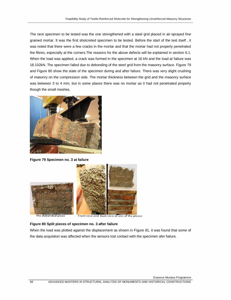
Feasibility Study of Textile Reinforced Shotcrete for Strengthening Unreinforced Masonry Structures
Erasmus Mundus Programme 58 ADVANCED MASTERS IN STRUCTURAL ANALYSIS OF MONUMENTS AND HISTORICAL CONSTRUCTIONS
The next specimen to be tested was the one strengthened with a steel grid placed in air-sprayed fine
grained mortar. It was the first shotcreted specimen to be tested. Before the start of the test itself , it
was noted that there were a few cracks in the mortar and that the mortar had not properly penetrated
the fibres, especially at the corners.The reasons for the above defects will be explained in section 6.1.
When the load was applied, a crack was formed in the specimen at 16 kN and the load at failure was
18.102kN. The specimen failed due to debonding of the steel grid from the masonry surface. Figure 79
and Figure 80 show the state of the specimen during and after failure. There was very slight crushing
of masonry on the compression side. The mortar thickness between the grid and the masonry surface
was between 3 to 4 mm, but in some places there was no mortar as it had not penetrated properly
though the small meshes.
Figure 79 Specimen no. 3 at failure
Figure 80 Split pieces of specimen no. 3 after failure
When the load was plotted against the displacement as shown in Figure 81, it was found that some of
the data acquistion was affected when the sensors lost contact with the specimen afer failure.

Feasibility Study of Textile Reinforced Shotcrete for Strengthening Unreinforced Masonry Structures
Erasmus Mundus Programme ADVANCED MASTERS IN STRUCTURAL ANALYSIS OF MONUMENTS AND HISTORICAL CONSTRUCTIONS 59
Figure 81 Graph of load vs. displacement at mid-span for the third specimen
The fourth specimen to undergo testing was the one strengthened with a basalt grid placed in sprayed
mortar. The first crack appeared at around 2.5 kN near the midspan. The crack increased in width with
time and the specimen finally failed due to the tensile fracture of the fibres. The maximum applied load
was only 4.642 kN but the failure was ductile. The fibres were in tension. The test was stopped even
though the specimen had not split into pieces because in the case of basalt, the rovings are composed
of many filaments and are strong , so it takes long to break each roving. The transfer of stresses
between the basalt fibres and mortar was not as effective as it should have been as the mortar had
not wetted the fibres very well.
Figure 82 Failure of the specimen due to tensile fracture of basalt fibres

Feasibility Study of Textile Reinforced Shotcrete for Strengthening Unreinforced Masonry Structures
Erasmus Mundus Programme 60 ADVANCED MASTERS IN STRUCTURAL ANALYSIS OF MONUMENTS AND HISTORICAL CONSTRUCTIONS
The load-displacement plot indicating the maximum load is shown in Figure 83.
Figure 83 Graph of load vs. displacement at mid-span for the fourth specimen
The fifth specimen was the first double-layered specimen to be tested. It was strengthened with two
grids of basalt and the mortar was applied by spraying. The specimen showed first signs of cracking
on both sides of the centre of the beam at a load of 11.5 kN, unlike the previous specimen with a
single layer of basalt grid which could withstand a maximum load of just 4.642 kN. The failure was
ductile again and the maximum load it withstood was 14.98 kN. Failure was due to tensile fracture of
the fibres accompanied by a minor compressive fracture of the masonry. Figure 84 shows the failure
mode of spesimen no. 5. It was found that there was a maximum thickness of 2mm of mortar between
the basalt fibres and the surface of the masonry. In some places it was just 1 mm of mortar and in
some places, no mortar had penetrated through. The mortar thickness between the two basalt grids
was 5 mm. The load-displacement plot for the mid-span is seen in Figure 85.
Figure 84 Tensile failure of fibres in specimen reinforced with double-layered basalt grid

Feasibility Study of Textile Reinforced Shotcrete for Strengthening Unreinforced Masonry Structures
Erasmus Mundus Programme ADVANCED MASTERS IN STRUCTURAL ANALYSIS OF MONUMENTS AND HISTORICAL CONSTRUCTIONS 61
Figure 85 Graph of load vs. displacement at mid-span for the fifth specimen
The next specimen was again composed of a double layer of reinforcement, but they were made of
glass. The mortar had been sprayed on in this case too. The first crack appeared at a load of 7 kN and
then cracks appeared on both sides of the central portion of the beam. Figure 86 displays the initial
cracks that appeared in the beam.
Figure 86 Initial cracking of the beam
It initially appeared to fail in flexure, but then it gave rise to a shear failure. The specimen failed by
shearing between the first and second brick as seen in Figure 87. The maximum load taken by the
beam was 14.969 kN. The specimen at failure is shown in Figure 88.

Feasibility Study of Textile Reinforced Shotcrete for Strengthening Unreinforced Masonry Structures
Erasmus Mundus Programme 62 ADVANCED MASTERS IN STRUCTURAL ANALYSIS OF MONUMENTS AND HISTORICAL CONSTRUCTIONS
Figure 87 Shearing process of the specimen
Figure 88 Specimen no. 6 at failure
On closer examination of the sheared specimen, a peeling of the brick surface was observed. The
layer of mortar in between the fibres and masonry surface was about 4 mm on average. However the
mortar layer between the two grids was just 2 mm. The graph of load versus mid-span displacement
was plotted and is seen in Figure 89.

Feasibility Study of Textile Reinforced Shotcrete for Strengthening Unreinforced Masonry Structures
Erasmus Mundus Programme ADVANCED MASTERS IN STRUCTURAL ANALYSIS OF MONUMENTS AND HISTORICAL CONSTRUCTIONS 63
Figure 89 Graph of load vs. displacement at mid-span for the sixth specimen
The next specimen to undergo testing was the one strengthened with carbon grid, where the mortar
had been applied manually. Cracks appeared in the mortar all of a sudden and it failed due to flexure.
Debonding of fibres took place. The maximum load that was withstood by the beam was 6.342 kN.
Figure 90 shows the carbon grids debonding from the mortar.
Figure 90 Failure of specimen no. 7 by debonding of textile grid
After the failure, the specimen was examined and it was observed that the penetration of the mortar
was very poor. This is due to the narrow mesh size of the carbon grid. The textile debonded from the
substrate, but it was intact. This is attributed to the fact that the carbon grid is very stiff and acts as a
continuous material. The mortar thickness between the fibre and the masonry surface was about 8
mm. It was very easy to take out the mortar from between the mesh as it was almost just superficially

Feasibility Study of Textile Reinforced Shotcrete for Strengthening Unreinforced Masonry Structures
Erasmus Mundus Programme 64 ADVANCED MASTERS IN STRUCTURAL ANALYSIS OF MONUMENTS AND HISTORICAL CONSTRUCTIONS
attached. This is apparent from Figure 91. The peak load is seen in the graph of load versus mid-span
displacement in Figure 92.
Figure 91 Mortar layer just superficially attached to the textile grid with enlarged detail
Figure 92 Graph of load vs. displacement at mid-span for the seventh specimen
The eighth specimen was reinforced with a glass grid placed in sprayed mortar. As the sensors were
not in contact with the specimen during the beginning of the experiment, the specimen had to be
unloaded and the procedure was restarted. There was a central crack formed initially, which gave rise

Feasibility Study of Textile Reinforced Shotcrete for Strengthening Unreinforced Masonry Structures
Erasmus Mundus Programme ADVANCED MASTERS IN STRUCTURAL ANALYSIS OF MONUMENTS AND HISTORICAL CONSTRUCTIONS 65
to an opening as the load was increased. Figure 93 shows the fallen mortar from the opening formed
due to the onset of flexural failure.
Figure 93 Formation of opening with stretching of fibres
The load rate was increased to 10 mm/min as it takes a long time to break the individual fibres of the
mesh. The type of failure was initially flexural, but then it gave rise to shear failure as in the previous
cases of glass reinforced specimens, accompanied by some crushing at the top of the beam. The
ultimate load withstood by the specimen was 10.031 kN.
Figure 94 Shear failure onset It was found that the bond between the glass grid and the mortar was good. The mortar layer between
the fibres and the masonry had a thickness that varied from 3 to 5 mm. Figure 95 shows the pieces of
the specimen after failure, where one can observe the textile embedment details and Figure 96 shows

Feasibility Study of Textile Reinforced Shotcrete for Strengthening Unreinforced Masonry Structures
Erasmus Mundus Programme 66 ADVANCED MASTERS IN STRUCTURAL ANALYSIS OF MONUMENTS AND HISTORICAL CONSTRUCTIONS
the load –displacement plot for specimen number eight. The initial data points correspond to the
values from the loading and subsequent unloading of the specimen as the sensors weren’t in position.
Figure 95 Broken specimen showing good bond between glass grid and mortar
Figure 96 Graph of load vs. displacement at mid-span for the eighth specimen
The ninth specimen was reinforced with one layer of glass grid on either side. This was done in view
of testing the effect of the increase in the number of reinforced sides. The specimen had some initial
drawbacks as the mortar had been sprayed irregularly, resulting in very thick portions of mortar in
some places. The mortar layer on the compression side was thicker than the one on the tension side
as 5 mm nuts had been used to glue the grid to the masonry surface on the former and 3 mm nuts had
been used for the latter. The first crack appeared near the mid-span at a load of around 4.7 kN. The
cracked mid-section is seen in Figure 97.

Feasibility Study of Textile Reinforced Shotcrete for Strengthening Unreinforced Masonry Structures
Erasmus Mundus Programme ADVANCED MASTERS IN STRUCTURAL ANALYSIS OF MONUMENTS AND HISTORICAL CONSTRUCTIONS 67
Figure 97 Initial cracking of specimen no. 9
The specimen started failing in flexure and then gave rise to shear as in the previous cases of glass
grid reinforced specimens.Figure 98 and Figure 99 show different stages of the failure. The maximum
load it could carry was 8.339 kN. This shows that the TRSc overlay on the compression side did not
increase the strength of the specimen. There was hardly any mortar between the fibre and the
masonry surface at the centre but it gradually increased in thickness and towards the edges of the
specimen, the thickness of the mortar layer was about 4 mm.
Figure 98 Widening of the crack and onset of shearing action
Figure 99 Glass fibres in tension The load versus displacement at mid-span was plotted in a graph and shown in Figure 100.

Feasibility Study of Textile Reinforced Shotcrete for Strengthening Unreinforced Masonry Structures
Erasmus Mundus Programme 68 ADVANCED MASTERS IN STRUCTURAL ANALYSIS OF MONUMENTS AND HISTORICAL CONSTRUCTIONS
Figure 100 Graph of load vs. displacement at mid-span for the ninth specimen
The last specimen to be tested was another carbon grid reinforced specimen where the mortar had
been sprayed on the surface. The failure in this case was also sudden and the split specimen can be
seen in Figure 101. The maximum load it could withstand was 6.806 kN which was similar to the other
specimen that had been reinforced with a carbon grid placed in sprayed mortar. The mode of failure
was again by debonding of the grid.
Figure 101 Sudden failure of the specimen
The carbon grid was intact as in the case of specimen number 7 . The mortar thickness between the
grid position and the masonry surface ranged from 1 to 3 mm. In some places, there was no mortar

Feasibility Study of Textile Reinforced Shotcrete for Strengthening Unreinforced Masonry Structures
Erasmus Mundus Programme ADVANCED MASTERS IN STRUCTURAL ANALYSIS OF MONUMENTS AND HISTORICAL CONSTRUCTIONS 69
that had penetrated. Figure 102 shows the two portions of the specimen after failure and Figure 103 is
the load-displacement plot for the mid-span.
Figure 102 Split pieces of the specimen on failure
Figure 103 Graph of load vs. displacement at mid-span for the tenth specimen
In general , it was observed that the specimens reinfored with glass grids failed in shear or by a
flexural failure that gave rise to shear. The failure exhibited by specimens strengthened with basalt
was ductile. Carbon and steel strengthened specimens failed mostly by debonding. Any discrepancy
in results could arise due to weak mortar joints, variations in sensor data due to loss of contact with
the specimen or interference from the elastomeric bearing supports.

Feasibility Study of Textile Reinforced Shotcrete for Strengthening Unreinforced Masonry Structures
Erasmus Mundus Programme 70 ADVANCED MASTERS IN STRUCTURAL ANALYSIS OF MONUMENTS AND HISTORICAL CONSTRUCTIONS
6. DISCUSSION AND CONCLUSIONS
Based on the experiments carried out, the observations made and the results obtained, the
conclusions drawn are elaborated in this section. The shortcomings of the shotcreting technique are
identified and ideas for future research work are enumerated.
6.1 ANALYSIS OF THE RESULTS AND CONCLUSION
On completion of the experiments, it is most certainly clear that the application of textile reinforced
shotcrete to unreinforced masonry structures is feasible and results in a huge savings in time. The
method of directly gluing the textile grid to the masonry surface with the aid of nuts and then spraying
the mortar is a novel one as per the author’s knowledge. It results in lesser mortar consumption and
also cuts out the time required to apply an initial layer of mortar. If used in large scale operations,
strengthening works that would usually take days to complete by manual application, can be done in
the matter of a few hours by the spraying technique.
The nuts used served a dual purpose – to hold the grid in place temporarily, until the sprayed mortar
fixed it in place and also to serve as a marker to indicate the required thickness for a uniform mortar
layer. When the geometry of the elements used is larger, using the present technique of gluing the
textile grid to the surface of the structure might not be as effective, especially for heavy grids like steel.
Either the number of nuts used should be increased or an alternate method to temporarily fix the
textile grid onto the masonry substrate until the sprayed mortar sets it in place is required. With regard
to serving as an indicator for required mortar layer thickness, it did not work as well as expected as the
mortar layer had the required thickness only near the corners where it was attached and the layer
gradually decreased in thickness towards the centre of the specimen. Another option could be to use
nails instead- the textile grids could be attached to the nails, and the protruding nails would give an
idea of the required thickness of the overlay to the nozzleman and might result in a more uniform layer
of sprayed mortar.
The technique proved to be more effective than the manual application method only in the case of
glass grids. The increase in strength was more than double in the case of specimens reinforced with
glass grids and sprayed mortar compared to the one in which the glass grids were placed in mortar
that was applied by hand. This is due to the fact that the mesh size of the glass grids are much larger
when compared to the others and hence the penetration of the mortar was relatively higher when
compared to the other textile grids with smaller mesh sizes. The specimens reinforced with glass grids
mostly failed in shear or by a combination of flexure and shear.
For the specimens reinforced with carbon grids, the one with sprayed mortar outperformed the one
where the mortar had been applied manually. However, the gain in strength wasn’t much. The
maximum load that was taken by the former was 0.5 kN more than the latter. Due to the high strength

Feasibility Study of Textile Reinforced Shotcrete for Strengthening Unreinforced Masonry Structures
Erasmus Mundus Programme ADVANCED MASTERS IN STRUCTURAL ANALYSIS OF MONUMENTS AND HISTORICAL CONSTRUCTIONS 71
and stiffness of the carbon grids , failure occured by debonding. It is advisable to use a mortar of
strong bonding properties and of high strength along with the carbon grid to obtain desired results. As
the mortar used was a plastering mortar and did not have high strength, the carbon fibres debonded
from the mortar and were left intact , but this did not help the specimen much.
The specimens reinforced with basalt fibres showed the most ductile failure. This was expected as the
percentage elongation of the basalt fibres is the highest among all the other textile grids. The higher
density of fibres and the arrangement of the filaments in each roving are responsible for the behaviour
of the basalt grids. The rovings are composed of many filaments and are strong , so it takes long to
break each roving. The transfer of stresses between the basalt fibres and mortar was retarded due to
the fact that the fibres weren’t immersed in the mortar.
The specimens reinforced with steel grids displayed the highest gain in strength. The specimen which
was reinforced with steel grids placed in mortar applied manually could bear the maximum load. It was
32% stronger than its counterpart with sprayed mortar. The performance of the shotcreted specimen
decreased because the mortar couldn’t penetrate the mesh very well and there was only partial
contact with the masonry substrate. Due to the stiffness of the steel fibres, these specimens also failed
due to the debonding of the fibres from the surface of the masonry. The steel fibres undoubtedly result
in the highest increase in strength, but their potential can be fully tapped only when used with a mortar
that possesses good properties and another important requirement is that that fibres are completely
wetted by the mortar. In the absence of this , the steel fibres can never reach their full strenth. As the
steel grids were unidirectional , while all the other fibres were bi-directional , they could withstand
more load.
With respect to the number of layers of reinforcement, the two specimens that had a double layered
reinforcement performed very well. There was a 33% increase in strength in the specimen
strengthened with two layers of glass over the specimen strengthened with a single layer of glass.and
approximately a 70% gain in strength for the specimens strengthened with two layers of basalt. This
shows that with an increase in the number of layers of reinforcement, the strength of the specimen
increases. The effect was more pronounced in the basalt strengthened specimens because of the
ductile failure. The specimens also had a thicker layer of mortar between the masonry substrate and
the textile grid as there was light pressing and trowelling when the second grid was inserted.
The parameter of the number of reinforced sides was tested only using one specimen. The increase in
the number of reinforced sides does not appear to increase the strength of the specimens. In fact , the
specimen failed at a lower load than the specimen strengthened with a single layer of glass grid
embedded in shotcrete. The decrease in strength could also be attributed to the presence of weak
mortar joints. In any case, it can be deduced that increasing the number of layers of reinforcement is a
better option that increasing the number of reinforced sides.
The glass grids are the cheapest and can withstand the least ultimate load among all the other fibres,
but they performed relatively well in comparison. The use of glass grids placed in air-sprayed fine

Feasibility Study of Textile Reinforced Shotcrete for Strengthening Unreinforced Masonry Structures
Erasmus Mundus Programme 72 ADVANCED MASTERS IN STRUCTURAL ANALYSIS OF MONUMENTS AND HISTORICAL CONSTRUCTIONS
grained mortar can result in a very quick, less expensive and an effective strengthening technique.
The use of a higher strength mortar with better bonding properties would’ve undoubtedly enhanced
the strength of the specimen to a greater degree. When the requirement for increase in strength is
higher, more layers of reinforcement should be used. The appearance of the textile reinforced
specimens placed in sprayed mortar can be improved by carrying out smoothening operations and
ensuring that the nozzleman sprays the specimen carefully and in a correct manner. An outline of the
failure details of all the specimens is drawn up in Table 10.
Table 10 Details of the failure of the specimens
SPECIMEN NO.
PROPERTIES MAXIMUM LOAD (kN)
CAUSE OF FAILURE
THICKNESS OF
MORTAR(mm) NO. OF
ROVINGS
1 STEEL/HAND/
1 LAYER 26.545 Sudden- by
debonding Varies: 5-7 42
2 GLASS/HAND/
1 LAYER 6.65 Shear ≈7 11
3 STEEL/SPRAY/
1 LAYER 18.102 Debonding
Varies: 0-4 42
4 BASALT/SPRAY/
1 LAYER 4.642 Ductile-
Flexural Negligible 17
5 BASALT/SPRAY/
2 LAYERS 14.980 Ductile-
Flexural Varies: 0-2 17x2
6 GLASS/SPRAY/
2 LAYERS 14.969 Flexure and
shear ≈4 11x2
7 CARBON/HAND/
1 LAYER 6.342 Debonding Varies: 0-2 27
8 GLASS/SPRAY/
2 SIDES 10.031 Flexure and
shear Varies: 3-5 11
9 GLASS/SPRAY/
1 LAYER 8.339 Flexure and
shear Varies: 1-4 11
10 CARBON/SPRAY/
1 LAYER 6.806 Debonding Varies: 1-3 27

Feasibility Study of Textile Reinforced Shotcrete for Strengthening Unreinforced Masonry Structures
Erasmus Mundus Programme ADVANCED MASTERS IN STRUCTURAL ANALYSIS OF MONUMENTS AND HISTORICAL CONSTRUCTIONS 73
6.2 DRAWBACKS OF THE SPRAYING TECHNIQUE
The initial problems faced with regard to the shotcreting procedure was the securing of suitable
shotcreting equipment to spray the commercial mortars that have been specially developed for manual
application with specific textile grids. As the machine was not able to pump mortar containing fibres
and large aggregates , a mortar used for plastering works was used instead. The properties of this
mortar are not as good as the ones that were intended to be used in the experiment.
Some of the other problems encountered during or after the shotcreting process are as follows:
Bonding of the TRSc at the edges and corners is problematic if the sprayed mortar is not applied
uniformly over the entire surface of the specimen. This was observed in some of the specimens,
especially in the ones reinforced with carbon grids. Since the mesh size of the carbon grids is small, in
some places the mortar penetrated theough the holes but did not manage to form a bond between the
masonry substrate and the textile reinforcement. An example is seen in Figure 104.
Figure 104 Improper bonding of TRSc with the substrate The steel grids faced the same problem of insufficient wetting of the fibres and improper penetration of
the mortar due to the small mesh size as seen in Figure 105.

Feasibility Study of Textile Reinforced Shotcrete for Strengthening Unreinforced Masonry Structures
Erasmus Mundus Programme 74 ADVANCED MASTERS IN STRUCTURAL ANALYSIS OF MONUMENTS AND HISTORICAL CONSTRUCTIONS
Figure 105 Result of inefficient spraying and small mesh size
In specimen no. 9, an extra layer of sprayed mortar is observed all around the edges of the specimen.
In order to avoid unsprayed edges as in some of the previous specimens, the operator sprayed
another layer of mortar along the perimeter of the specimen as seen in Figure 106. This affected the
aesthetic appearance of the specimen and also resulted in a very non-uniform layer of TRSc.
Figure 106 Extra layer of mortar sprayed along the perimeter in the specimen number 9
In some of the specimens, the layer of sprayed mortar formed exceeded the required thickness, and
this resulted in crack formation. Improper shotcreting practices led to problems in bonding of the
reinforcement at the edges. This is seen in Figure 107.

Feasibility Study of Textile Reinforced Shotcrete for Strengthening Unreinforced Masonry Structures
Erasmus Mundus Programme ADVANCED MASTERS IN STRUCTURAL ANALYSIS OF MONUMENTS AND HISTORICAL CONSTRUCTIONS 75
Figure 107 Defects due to improper spraying technique
There are some issues that need to be tackled when this technique is used in large-scale applications.
One of them is the hardening of mortar when kept for long intervals. In case this happens, the delivery
pipe may get blocked and then some of the components of the machine have to be dismantled and
reassembled after cleaning them. Another issue that needs to be considered is the transport of the
heavy machine between floors when used in multi-storeyed structures. The nozzleman has to also
spray the specimens carefully and in a systematic way, making sure that even the edges of the
specimen have been sprayed.
6.3 SCOPE FOR FUTURE RESEARCH
Owing to the constraint in time , the project involved the testing of a limited number of samples.
Although it is sufficient to prove that the technique is feasible, more testing would have to be carried
out to get a better idea about the best fibre-mortar combination and study possible methods of
improvement in embedding the textile in sprayed mortar.
As far as the aesthetic appearance of the specimens is concerned, it is advisable to smoothen the
surface after shotcreting is carried out. As this thesis was focussed on studying the effectiveness of
the shotcreting technique, it was decided against carrying out any smoothening operations as this
could introduce additional forces or bring about changes in the bonding process that would normally
occur just by the spraying action.
As the mortar used was just a plastering mortar and not of the quality of mortars usually used for TRM
applications, future work could concentrate on finding a mortar with good bonding properties,
compatible with textile reinforcement and that can be projected easily onto the surface of masonry. An
alternative would be to invest in shotcreting equipment that can project mortars with larger aggregates

Feasibility Study of Textile Reinforced Shotcrete for Strengthening Unreinforced Masonry Structures
Erasmus Mundus Programme 76 ADVANCED MASTERS IN STRUCTURAL ANALYSIS OF MONUMENTS AND HISTORICAL CONSTRUCTIONS
and fibres. Since sprayable versions of high performance fiber-reinforced cement-based composites
better known as engineered cement composites have been developed for the market, the machines
used in these processes can be adapted for the use of commercially available mortars used in normal
TRM applications.

Feasibility Study of Textile Reinforced Shotcrete for Strengthening Unreinforced Masonry Structures
Erasmus Mundus Programme ADVANCED MASTERS IN STRUCTURAL ANALYSIS OF MONUMENTS AND HISTORICAL CONSTRUCTIONS 77
7. REFERENCES
ACI Committee 506. Guide to Shotcrete. American Concrete Institute, 1985.
Ashurst, John, and Nicola Ashurst. Practical Building Conservation , Volume 2-Brick,Terracota and
Earth. Great Britain: Antony Rowe Ltd, 1998.
Bláha, Jiří, Pere Roca, Climent Molins, and Francisco Fernandes. “Construction technologies and
structural components-Masonry and Earth.” Lecture Notes- SAHC. 2011.
CINTEC. Reinforcement of Masonry Structures. http://www.cintec.com/blastec/structure-
reinforcement.php (accessed June 16, 2012).
D'Ayala, Dina. “UNREINFORCED BRICK MASONRY CONSTRUCTION.” http://www.world-
housing.net/. http://www.world-housing.net/wp-content/uploads/2011/08/Type_Brick.pdf.
Díez, Jesus, David García, Iñaki Marcos, and Tomás San. “Strengthening solutions applied to stone
masonry walls: TRM technology.” REHABEND: Jornadas Internacionales sobre la Tecnología de la
Rehabilitación y la Gestión del Patrimonio Construido: Santander. 2007.
Drdacky, Milos, and Jan Valek. SAHC Lecture notes- Consolidation of degraded brick and masonry.
Prague, 2011.
Ehsani, M R, H Saadatmanesh, and J I Velasquez-Dimas. “Behaviour of Retrofitted URM Walls under
Simulated Earthquake Loading.” Journal of Composites for Construction- ASCE, 1999: 134-142.
ElGawady, M, P Lestuzzi, and M Badoux. “A Review of Conventional Seismic Retrofitting Methods for
Masonry.” 13th International Brick and Block Masonry Conference. Amsterdam, 2004.
ElGawady, M. A., P. Lestuzzi, and M. Badoux. “Retrofitting of Masonry Walls Using Shotcrete.” New
Zealand Society for Earthquake Engineering Conference 2006. Wellington, 2006.
Gonzalez, Rosángel Moreno, Lluís Pujades Beneit, Alejandro Horia Barbat, and S Lagomarsino.
“Seismic risk of traditional unreinforced masonry buildings of Barcelona, Spain.” 1-9.
Hankers, Christoph, and Dirk Matzdorff. “Strengthening reinforced concrete elements using textile
reinforced shotcrete.” www.torkret.de. http://www.torkret.de/unternehmensgruppe/planung.html
(accessed June 10, 2012).

Feasibility Study of Textile Reinforced Shotcrete for Strengthening Unreinforced Masonry Structures
Erasmus Mundus Programme 78 ADVANCED MASTERS IN STRUCTURAL ANALYSIS OF MONUMENTS AND HISTORICAL CONSTRUCTIONS
Harajli, M. H., H. El Khatib, and J. Tomas San-Jose. “Masonry Walls Strengthened Using Fibre
Textile-Mortar System: Experimental Evaluation of Out-of-Plane Cyclic Response.” Ottawa, 2010. 19-
31.
Ismail, Najif, and Jason M Ingham. “State-of-the-art retrofit interventions for unreinforced masonry
walls.” http://www.najif.net/. 2007. http://www.najif.net/wp-content/uploads/2007/12/poster-najif-
081124.pdf (accessed May 24, 2012).
MAPEI. “Mapegrid G220.” http://www.mapei.com. August 2006.
http://www.mapei.com/public/COM/products/1033_mapegrid%20g220_gb.pdf (accessed May 22,
2012).
“Planitop HDM Restauro.” www.mapei.com. February 2012.
http://www.mapei.com/public/COM/products/1071_planitop%20hdm%20restauro_gb.PDF (accessed
May 2012, 10).
Münich, Johannes Christian, Heike Metschies, Lothar Stempniewski, and Holger Erth. “Hybrid Textile
Reinforcement In A Cement Based Matrix for Retrofitting of Masonry.” Fourth International Conference
on FRP Composites in Civil Engineering. Zurich, 2008.
Papanicolaou, Catherine G, Thanasis C Triantafillou, Myrto Papathanasiou, and Kyriakos Karlos.
“Textile reinforced mortar (TRM) versus FRP as strengthening material of URM walls: out-of-plane
cyclic loading.” Materials and Structures, 2008: 143–157.
Papanicolaou, Catherine, Thanasis Triantafillou, and Maria Lekka. “Externally bonded grids as
strengthening and seismic retrofitting materials of masonry panels.” Construction and Building
Materials, 2011: 504–514.
Ruredil. “Ruredil X Mesh C10 Composite structural reinforcement for masonry structures.”
www.ruredil.it. November 2008. http://www.ruredil.it/ENG/PDFCataloghiENG/RXMeshC10.pdf
(accessed May 16, 2012).
“Ruredil X Mesh C10 M25.” www.ruredil.it. October 2009.
http://www.ruredil.it/ENG/SchedeProdottoENG/RuredilXMeshC10M25Ing_1.pdf (accessed May 10,
2012).
San-José, J T, D García, El T Hadid, R San-Mateos, A Al Far, and I Marcos. “Novelty FRP and TRM

Feasibility Study of Textile Reinforced Shotcrete for Strengthening Unreinforced Masonry Structures
Erasmus Mundus Programme ADVANCED MASTERS IN STRUCTURAL ANALYSIS OF MONUMENTS AND HISTORICAL CONSTRUCTIONS 79
Strengthening Systems Applied to stone Masonry Walls: Experimental Programme Presentation (I).”
Asia-Pacific Conference on FRP in Structures ,International Institute for FRP in Construction. Hong
Kong, 2007.
Taghdi, Mustafa, Michel Bruneau, and Murat Saatcioglu. “Seismic retrofitting of low-rise masonry and
concrete walls using steel strips.” Journal of structural engineering, 2000: 1017-1025.
Triantafillou, Thanasis. “Innovative Textile-Based Composites for Strengthening and Seismic
Retrofitting of Concrete and Masonry Structures.” Advances in FRP Composites in Civil Engineering:
Proceedings of the 5th International Conference. Beijing, China, 2010.
Wiberg, Anders. “Strengthening of Concrete Beams using Cementitious Carbon Fibre Composites.”
Stockholm, 2003.