Embed Size (px)
Citation preview

CR 159469
FEASIBILITY STUDY FOR A SECONDARY NaS BATTERY
FINAL REPORT for Period October 1 1977 - September 30 1978
(NASA-CR-159469) FEASIBILITY STUDY FOR A N79-17330 SECONDARY NaS BATTERY Final Report-1 Oct 1977-- 30 Sep 1978 (EIC- Inc Newton Mass) 65 p HC A04MF A01 CSCL 10C unclas
G344 14041
by
K M Abraham RSchiff S B Brummer
EIC Corporation 55 Chapel Street
Newton Massachusetts 02158
Prepared for
NATIONAL AERONAUTICS AND SPACE ADMINISTRATION Cleveland Ohio 44135
January 1979
CONTRACT NO NAS3-21028
NASA-Lewis Research Center n Cleveland Ohio 44135
Joseph Singer Project Manager
CR 159469
FEASIBILITY STUDY FOR A SECONDARY NaS BATTERY
FINAL REPORT
for Period October 1 1977 - September 30 1978
by
K M Abraham R Schiff S B Brummer
BIC Corporation 55 Chapel Street
Newton Massachusetts 02158
Prepared for
NATIONAL AERONAUTICS AND SPACE ADMINISTRATION
Cleveland Ohio 44135
January 1979
CONTRACT NO NAS3-21028
NASA-Lewis Research Center Cleveland Ohio 44135
Joseph Singer Project Manager
ABSTRACT
The feasibility of a moderate temperature Na battery having the configuration
Liquid Na Solid Electrolyte Dissolved Na2Sn ( -A1 2 03 ) or Metal Sulfide
has been studied This battery is to operate at a temperature in the range of 100-150degC Two kinds of cathode were investigated (i) a soluble S cathode consisting of a solution of Na2Sn in an organic solvent and (ii) an insoluble S cathode consisting of a transition metal dichalcogenide in contact with a Na+-ion conducting electrolyte
Four amide solvents dimethyl acetamide diethyl acetamide N-methyl acetamide and acetamide were investigated as possible solvents for the soluble S cathode Results of stability and electrochemical studies using these solvents are presented The dialkyl substituted amides were found to be superior
Although the alcohol 13-cyclohexanediol was found to be stable in the presence of Na2Sn at 1300C its Na2Sn solutions did not appear to have suitable electrochemical properties
The limited amount of work carried out with transition metal dichalcoshygenides indicates that they present interesting possibilities as cathode materials in a moderate temperature Na battery
ii
TABLE OF CONTENTS
Section Page
ABSTRACT ii
I INTRODUCTION 1
II THE Na-DISSOLVED S BATTERY 5
A Aliphatic Amides as Solvents for the Dissolved S Cathode 5
1 Solubilities of Na2S in Amide Solvents 5
2 Stabilities of Amide Solvents in the Presence of Na2Sn at 1300C 10
3 Sodium-Sulfur Cell Studies with CH3CONR2Na2Sn Cathodes 32
B Sodium-Sulfur Cell with a 13 Cyclohexanediol (CHD)Na2Sn Cathode 40
1 Cell with CHDNa2SO5M NaBr Solution as the Initial Catholyte 40
2 Cell with CHDNa2S4O5M Nal Solution as the Initial Catholyte 42
III THE Na-TRANSITION METAL SULFIDE BATTERY 44
A Preparation and Characterization of the Disulfides 44
1 Titanium Disulfide TiS 2 44
2 Tantalum Disulfide TaS2 47
B Stability Characteristics of Metal Sulfide Amide Mixtures 47
C Electrochemical Evaluation of Transition Metal Disulfides 47
1 Titanium Disulfide as the Cathode 47
2 Tantalum Disulfide as a Cathode 49
IV SUMMARY AND CONCLUSIONS 56
V REFERENCES 57
iii
LIST OF ILLUSTRATIONS
Figures Page
1 Experimental set-up for determination of Na2Sn solubilities 8
2 A) Sample tube for stability test B) Manometer assembly 13
3 Absorption spectra of DMAC or DMACNa 2S solutions before and after heating at 130C 19
4 Vapor phase IR spectrum of the gases from ACNa2S solution after 18 days of heating 20
5 Visible spectrum of a solution of Na2 Sn in DMAC after heating for 21 days at 1300C 22
6 A plot of the amount of gas produced vs heating time for amideNa2Sn solutions 23
7 Vapor phase infrared spectrum of gases from DMAC Na2S8 solution after 21 days of heating at 1300C 24
8 Visible spectra of solutions of Na2S8 in DMAC 25
9 Visible absorption spectra of the DEACS reaction product in solution 26
10 Visible absorption spectra of the DMACS reaction product in solution 27
11 Vapor phase infrared spectrum of the gases from DMACS solution after 21 days of heating at 130C 29
12 Mass spectrum of the gases from DMACS solution after 21 days of heating at 1300C 30
13 High temperature electrolytic cell having a -AI203 separator 33
14 Galvanostatic charge (C)discharge (D) curves for a cell of configuration molten NaS-A1203Na2S4 (24M S) NaBF4 (004M) DMACcarbon felt at 1300C 34
iv
LIST OF ILLUSTRATIONS (continued)
Figures Page
15 The third discharge (3C) and fourth discharge (4D) curves for a cell liquid Naa-A1203Na2S4 (4M S) 075M NaI DMACTeflon-bonded C electrode at 1300 C 35
16 Galvanostatic dischargecharge curves for a cell liquid Na0-Al203Na2S4 (2M S) 05M NaI DEAC Teflon-bonded C electrode at 130C 37
17 The third discharge (3D) third charge (3C) and fourth discharge (4D) curves for the cell shown in Fig 16 38
18 Cycles five through ten of the cell shown in Fig 16 39
19 Galvanostatic chargedischarge liquid Na0-A1203Na2S (2M S) bonded C at 130C
curves for a cell 05M NaBr CHDTeflonshy
41
20 Galvanostatic dischargecharge curves for the cell liquid Na-AI203CD 05M NaI 2M S as Na2S4 (9 ml) Teflon-bonded C at 130degC 43
21 The dischargecharge curves for the cell liquid
Na0-A1203DMAC (1M NaT) TiS 2 at 1300C 50
22 Galvanostatic dischargecharge curves for the cell liquid Na0-A1203DMAC (1M NaI) TiS2 at 1300C 51
23 The galvanostatic discharge curve for the cell liquid Na0-A1203DMAC (IM NaI) TaS2 at 1300C 53
24 Galvanostatic dischargecharge curves A and B for the cell liquid Na$-Al203DMAC (1M NaI) TaS2 at 1300C 55
v
LIST OF TABLES
Tables Page
1 SOME PHYSICAL PROPERTIES OF ACETAMIDE N-METHYL-ACETAMIDE DIMETHYLACETAMIDE AND DIETHYLACETAMIDE 6
2 SOLUBILITY DATA FOR Na2Sn 150 0C
IN AMIDE SOLVENTS AT
ii 11
3 STABILITY TEST DATA FOR ACETAMIDENa2 Sn MIX-TURES AT 130C 15
4 STABILITY TEST DATA FOR NMACNa2Sn
AT 1300 C MIXTURES
16
5 STABILITY TEST DATA FOR DIMETHYLACETAMIDENa2 Sn MIXTURES AT 1300 C 17
6 STABILITY TEST DATA FOR DEACNa2Sn MIXTURES AT
1300C 18
7 TEMPERATURE PROFILE FOR THE PREPARATION OF TiS2 FROM Ti AND S 45
8 X-RAY DIFFRACTION DATA CALCULATED FOR HEXAGONAL TiS2 AND OBSERVED LINES OF SAMPLES PREPARED BY THE PRESENT PROCEDURE 46
9 STABILITY TEST DATA FOR AMIDETiS2 MIXTURES AT 1300C 48
vi
I INTRODUCTION
The aim of this research program has been to investigate the feasishybility of a moderate temperature secondary Na battery utilizing S cathodes The S cathode is either in the dissolved form as Na sulfides Na2Sn n _ 1 in a suitable organic or inorganic solvent or in the insoluble form as a transition metal sulfide such as TiS 2 This system having the cell conshyfiguration
Liquid Na Solid Electrolyte Dissolved Na2Sn or metal sulfide
is aimed at high energy density and high power density applications and is expected to have an operating temperature in the range of 1000 to 150degC The solid electrolyte is S-A1203 an ionic conductor permeable only to Na+ ions
The dissolved S cathode battery would be a modification of the much researched (12) system
Liquid Na S-A1203Molten S
The latter system was first described by Kummer and Weber (3) In this system the fully charged cathode usually consists of a conductive graphite felt matrix imbedded in a pool of nonconductive liquid S During disshy
+charge Na ions migrate through the solid electrolyte to form various Na polysulfides (Na2Sn) at the surface of the porous graphite cathode The initial discharge reaction is believed to be
2Na + 5S + 2e - Na2S5 (1)
Further discharge products would involve S4- 2 and S3-2 species coupled with chemical steps involving ion-radical species The operation of the system however is temperature-limited and further complicated by formashytion of various phases as described in its phase diagram (4) Upon discharge insoluble Na2S 3 precipitates out when the overall composition reaches a critical value Because of the solidification of Na2S3 the lower limit of the operating temperature is 300C Furthermore on charge when the overall composition exceeds Na2S5 two immiscible liquid phases
(Na2 S5 S) coexist of these the S phase is nonconductive The porous graphite cathode operation is believed to be transport-limited (5) as a result of the high exchange current density the complicated phaseshyrelationship and the nonconductivity of S-rich phase
Since the discharge reaction stops at Na2S 3 the attainable energy density of this system is considerably less than that corresponding to the theoretical reaction
2Na + S - Na2S (u700 Whrlb) (2)
The theoretical energy density with an end-of-discharge composition of Na2S3 is 345 Whrlb The high operating temperature (gt3000 C) of the molten S system has introduced severe problems in the implementation of this battery concept The successful development of the battery is contingent upon solving severe corrosion and materials problems Cell failures occur because of accumulation of sensitive materials on the positive electrode deterioration of the solid electrolyte or of seals or more general corshyrosion (51) These problems fundamentally result from operation at very high temperature
It is evident that many of the problems encountered in the Namolten S system could be resolved by lowering the operating temperature One way to achieve this is to use a S cathode as Na sulfides dissolved in a solvent so that the operating temperature is just above the melting point of Na ie in the range of 100 to 150C In this case if the solvent dissolves appreciable amounts of Na2S it might be possible to achieve the end-ofshydischarge composition closer to the theoretical Na2S Also the use of a solvent which dissolves appreciable amounts of Na-polysulfides (ie Na2Sn where n gtgt 5) could eliminate the undesirable phase separation problems encountered in the molten S battery
An alternative approach is to use an insoluble transition metal sulshyfide cathode in contact with a Na+-ion containing electrolyte so that during discharge the cell reaction is the intercalation of Na into the sulfide lattice as depicted in Equation 3
MS2 + Na + e- l NaMS2 (3)
Some solution to this problem has been found (1) by the use of metal sulfide additives such as FeS to the molten S cathode
2
Such a battery would be analogous to the ambient temperature LiTiS2 cell and should operate conveniently at a temperature in the range of 100 to 1500C
The major advantages of a moderate temperature system are
1 Minimal problems from corrosion seal fracture and thermal cycling
2 Less expensive and simpler sealing procedures eg the use of plastics becomes possible below 20000
3 Less insulation and hence less weight and cost making smaller battery packages economical
A preliminary battery design with a soluble S cathode indicates that for an end-of-discharge composition of Na2S a charged-state S solubility of 16M in S8 is required to give an energy density comparable to that of a molten S battery designed for 100 Whrlb performance On the other hand if the end-of-discharge product is Na2S2 the required S8 concentration is 33M We must of course take into account that compared with operation at 300-350C there will be some energy loss due to increased resistance of the 0-A1203 and possibly from polarization losses at the electrodes The resistivity of $-A1203 at 3000C is v3 ohmcm and at 150C it is 18 ohmcm With tubes 08 mm thick and discharge rates of 50 mAcm 2 this involves a loss of 0012V at 3000C and 0072V at 1500C Since the OCV is 208V there is a corresponding additional loss from working at lower temperatures of 3 In the high temperature cell there is a further ohmic drop in the catholyte compartment about equal to that of $-A1203 (7) We can expect at least this additional loss at the lower temperature Thus the overall energy loss from ohmic polarization in a soluble S battery would be of the order of 10 Although the additional ohmic voltage drops associated with operation at lower temperature will effect the batterys ability to deliver the required energy density at the highest rates it is not improbable that at less than the highest rates the soluble S battery (1500C) could achieve energy density comparable to the molten S battery (3500C) Rate goals of 25 mAcm2 at 18V seem reasonable for most applications
The moderate temperature Na battery is analogous to the NaSbCI3 battery under development with EPRI support for electrical load-levelling (8) The latter battery is to operate at 200 0C with current densities up to 25 mAcm2 of 0-A1203 It is projected to have power densities of b50 mWcm2 This battery overcomes one of the major difficulties of the Na molten S system that of sealing Plastic seals appear to be satisfactory (9)
3
A preliminary study carried out at EIC (10) has shown the basic feasibility of the liquid Nadissolved S battery concept In this study a liquid NaS-A 203dissolved S cell utilizing NN-dimethyl acetamide (DMAC) as the S-solubilizing agent exhibited during short term cycling studies good reversibility between voltage limits of 100 and 270V The average cycling stoichiometry at 1300C corresponded to
-5S2-2 Z S 0 2 + 8e- (4)
No elemental S was formed during cell charging but only long chain soluble polysulfides The major system limitation was found to be the termination of discharge (sharp voltage cut-off to 100V) in the vicinity of a polysulfide composition of S2- 2 The principal reasons for this appeared to be the very low solubilities of the lower order polysulfides and the consequent choking of the carbon felt current collector by the precipitated Na sulfides
Studies (10) of Na2S in various aliphatic amides had shown-that its solubility decreased with increasing N-alkyl substitution Thus acetamide (AC) N-methylacetamide (NMAC) and dimethylacetamide (DIAC) dissolved Na2S in the amounts of 110 060 and 00075 MQ respectively at 150CC The long term stability characteristics of these amides in the presence of Na2Sn had not been determined
In the present program a detailed investigation was carried out to determine the suitability of the amides as solvents for the dissolved S cathode The major areas of investigation were solubility determinations of Na2Sn in the amides at 11500 C long term stability characteristics of the amides in the presence of Na2Sn at 130C and cell cycling studies in practical configuration utilizing S-A1203 as the solid electrolyte We have also evaluated 13 cyclohexanediol (CHD) as a possible solvent for the dissolved S cathode
The transition metal disulfides TiS2 and TaS2 were investigated as possible cathode candidates The studies included determination of their long term stabilities in the presence of DMAC or DEAC at 130C and evaluashytion of their cycling behavior in NaI solutions of these amides
4
II THE Na-DISSOLVED S BATTERY
The successful development of a Na-dissolved S battery is contingent
upon the selection of a high boiling solvent which shows high S solubility intrinsic thermal stability up to 150 0C and which is unreactive towards Na2Sn Our preliminary studies (10) had indicated that aliphatic amides were promising solvents with respect to many of these properties Another class of solvents showing appreciable solubilities of the Na sulfides
including Na2S was aliphatic alcohols The present study therefore
emphasized these two class of compounds
A Aliphatic Amides as Solvents for the Dissolved S Cathode
The suitability of aliphatic amides as solvents for the NaS battery
was evaluated by studying their ability to dissolve Na sulfides Na2Sn (n 1) at b1300 C their long-term stability properties in the temperature range of 100-1500 C and by examining the electrochemical behavior of solushy
tions of Na2Sn in these amides The aliphatic amides investigated in the program were AC NMAC DMAC and diethylacetamide (DEAC) Some physical properties of these solvents are shown in Table 1
1 Solubilities of Na2Sn in Amide Solvents
The solubilities of Na2Sn (n = 1 2 4 or 8) in each of the amides AC NMAC DMAC or DEAC at 150C were measured The experimental procedures and the results are given below
General Experimental
The experiments were carried out in the absence of air and moisshyture using standard techniques employed for the manipulation of air
sensitive compounds (11) Whenever appropriate the handling and transfer of reagents were also carried out in an argon-filled dry box (Vacuum-
Atmospheres Corporation)
Reagents
Commercially obtained reagents were purified as described below
Acetamide (Fisher Scientific Lot No 742523) was twiceshyrecrystallized from a mixture of methanol and diethyl ether In this proshycedure acetamide was initially dissolved in anhydrous Me0H (ig AC08 ml
MeOH) It was then crystallized out by adding anhydrous diethyl ether
5
Solvent
MP 0C
BP 0C
Density gml
Refractive
Index
Viscosity CP
Dielectric Constant
Min Specific Conductance (Q-1cm-1 )
TABLE I
SOME PHYSICAL PROPERTIES OF ACETAMIDE N-METHYLACETAMIDE
DIMETHYLACETAMIDE AND DIETHYLACETAMIDE
Acetamide N-methylacetamide NN-dimethyl acetamide
805 295 -20
2215 2060 165
0967 (1200C) 09503 (300C) 0936 (250c)
14274 (780C) 14277 (30CC) 14351 (250C)
106 (1200C) 3885 (30C) 92 (250C)
74 (250C extrap) 186 (250C extrap) 27 (250C)
- 726 x 10 6 (940C) 1 x 10- (400C) 20 (250C)
NN-diethyl acetamide
185
0924 (250C)
-
-
-
-
(rl0 ml Et20g AC) yielding long needle-like crystals The crystals were further dried in vacuum (i0-3 torr) by continuously pumping for ru20 hr The melting point of the twice-recrystallized material was found to be 78-790 C very close to the reported value (12) of 805degC
High purity N-methylacetamide obtained from Aldrich Chemical Co
(Lot No 021777) was used after the following treatment for removal of its water content About 100g of NMAC was dissolveamp in r100 ml anhydrous diethyl ether and the solution was then passed through a chromatography column (15 cm ID and 28 cm long pyrex glass tube) packed with freshly regenerated Linde 41 molecular sieves The flow rate of the solution through the column was maintained at l mlmin The ether from the sieved solution was removed in vacuum by collecting it in a dry iceacetone cooled cold trap Final drying of the amide was carried out by continuously pumping it in vacuum at room temperature for u20 hr The NN-dimethylshyacetamide was obtained from Burdick and Jackson Laboratories Muskegan Michigan This material was of high purity distilled in glass quality The water content of the solvent was further reduced by passing over activated
Linde 4A molecular sieves Diethylacetamide was vacuum distilled first using a spinning band column (Perkin-Elmer Corp) and then dried over molecular sieves
Elemental S (Ventron random pieces) Na2S (Ventron) and Na2S4 (Ventron) were used as-received The polysulfides Na2S2 and Na2S8 were prepared from stoichiometric mixtures of Na2S and Na2S4 respectively with elemental S
e Solubility Determination
The experimental setup for solubility determination is shown in Figure 1 In a typical experiment a mixture consisting of an excess of the sulfide (equivalent to 2-12M S) and a known amount of the solvent (10 ml) was taken in A and the system was thoroughly flushed with dry N2 The mixture was then heated with stirring to 150C and maintained at this temperature for 3 hr for equilibration After the 3 hr of heating any undissolved sulfide was allowed to settle down Thereafter by maintaining a N2 flow the joint at B was disconnected and an aliquot of the sample was
withdrawn for analysis of total sulfur and S- 2 Sampling was done by means of a pipette which had been heated to 1500C using a heating tape Analytical procedures for sulfur determination are given below in detail
Fresh molecular sieves obtained from the manufacturer were regenerated by
heating at 400C under a stream of Ar for b16 hr About 030g of molecular sievesml of the solution was used Use of molecular sieves has been sugshygested as the best method for removal of H20 content of amide solvents (13)
7
A HiGH TEMPERATURE BATH
STIRRING BAR
Fig 1 Experimental set-up for determination of Na2 Sn solubilities
Sulfide Analysis
Sulfide analysis was carried out iodimetrically (14) It is based on the reactions
12 + Sn-2 nS + 21- (5)
2S203-2 + 12 $406-2 + 21- (6)
Samples of the polysulfide solution measuring 050 ml were quickly added to an excess of standardized 12 solution (005N) The solution was then titrated immediately with standard thiosulfate solution (005N) to a starch end point When sulfide solution is added to 12 solution a white to offshywhite precipitate is formed at the neutral point The precipitate is elemental S Equation 5 In the presence of excess 12 the solution has a yellow to pink color showing unreacted iodine Sodium thiosulfate
-2neutralizes this iodine according to Equation 6 The S concentration is calculated from the amount of iodine consumed
0 Total Sulfur Analysis
Total S analysis was carried out by oxidation of the polysulfide - 2to S04 with H202 in ammoniacal medium and determination of S04-2 by titrashy
tion with standardized Ba(Cl04)2 solution (15)
2 + (2n-2) OH + (2n+l) H20 2 nSO4-2 + 4n H2 0 (7)
A sample of the nonaqueous polysulfide solution 050 ml was withdrawn An excess of 50 NH4OH followed by excess 30 H202 were immediately added until a colorless solution was obtained within a few minutes The solution was then heated to boiling to destroy unreacted H202 and to insure complete oxidation of S Heating was continued to drive off all the NH3 The solushytion was then diluted to 50 ml adjusting the pH to 25-40 with 1N HC (Very little or no acidification should be necessary if the NH3 is completely_ removed) To a 2-5 ml aliquot sufficient CH30H was added to make the solution 80 One drop of thorin indicator solution (02) was added and the solution was titrated with 0005M standardized Ba(Cl04)2 to a pink end point
The following procedures are important for obtaining accurate results
For very dilute S solutions a 15 dilution of the Ba(Cl04)2 should be used for titration The end point is indicated by a change from yellow to pink Practice is required to distinguish the intermediate orange from the final pink to within several drops (-002 mldrop in a 25 ml buret) It is helpful to have for comparison a sample that has been titrated beyond its end point
9
Results and Discussion
The solubilities at 1500C of Na2Sn n = 1 2 4 or 8 in AC NMAC DMAC and DEAC respectively are shown i4Table 2 It can be seen that AC dissolves 106M Na2 S and NMAC dissolves 075M Na2S In general the total S solubility in the two solvents is seen to increase with increasing polysulfide chain-length reaching an upper limit when the Sn-2 chain-length is 4 The solubility of Na2S in AC or NMAC at 1500C
is much higher than in DMAC The observed trend of AC gt NMAC gt DMAC for the Na2S-solubilizing properties of the three solvents is consistent with the increasing H-bonding ability in going from DMAC to AC Thus from the stand point of S solubility both AC and NMAC are superior to DMAC Howshyever preliminary stability studies carried out as described previously (10) along with the solubility experiments indicated that in the long run solushytions of Na2Sn in AC or NMAC might be less stable than solutions of Na2Sn in DMAC or DEAC
2 Stabilities of Amide Solvents in the Presence of Na2Sn at 130 0C
The ultimate usefulness of the amides as solvents for the S cathode in the NaS battery is dependent upon their long term stabilities The stability properties should include both intrinsic thermal stability and chemical compatibility with Na2Sn at temperatures 1300C A thorough invesshytigation of the long term stability characteristics of AC NMAC DMAC or DEAC in the presence of Na2Sn at 1300C has been carried out The procedure employed for this consisted of incubating amide solutions containing Nashysulfides at 1300 in sealed evacuated glass tubes equipped with breakshyseals The tubes were opened after known intervals of time (days) and the gas pressure in each tube was measured with a manometer The solution and gas products were analyzed spectrometrically
o Reagents
All the reagents used in these tests were carefully dried according to procedures outlined below
N-methylacetamide dimethylacetamide and diethylacetamide were dried andor purified as described earlier (Section IIAl) Acetamide was also purified by the recrystallization procedure described in Section IIAl However before recrystallization with Et20 the methanolic solution was dried by passing twice through a chromatography column containing moleshycular sieves
Sodium monosulfide Na2 S (Ventron) was dried by heating in vacuum at 5100C with continuous pumping for r16 hr After the heating some shrinking of the volume coupled with a slight darkening of the sulfide was observed
10
TABLE 2
SOLUBILITY DATA FOR Na2Sn in AMIDE SOLVENTS AT 150 0 C
Solvent Na2S Na2S2 Na2S4 Na2S8
(MS-21Z) (MS0I) (MSdegI) (MSdeg)
Acetamide 106 24 76 74
N-methylacetamide 075 18 62 70
Dimethylacetamide 00075 - 427 66
Diethylacetamide t 32 69
tApparently none dissolved -Not done
11
Sodium tetrasulfide Na2S4 (Ventron) was also dried in vacuum at 215degC with continuous pumping for 16 hr Elemental S (Ventron random pieces) was also dried in vacuum at ll0C for u24 hr At the end of the heating all the sulfur had sublimed off and condensed onto the cooler parts of the flask in which it was heated
Experimental Procedure
The test vessels consisted of pyrex tubes (30 ml capacity) equipped with break-seals as shown in Figure 2A Each tube was also provided with ground glass joints A and B for attachment to the vacuum system The accurate volume of each tube was obtained by measuring the amount of water it required to fill the tube In a typical experiment weighed amounts of the sulfide or S and the amide were charged into the
-reaction tube inside a dry box The tube was then evacuated at 10 3 torr and sealed off at C The hermetically sealed tube was heated at 1300C in a constant temperature oven (Tenney Environmental Chamber) for a known period of time Three sample tubes were used for each solution to be tested so that the tubes could be opened after different periods of heating Before the tube was opened for measuring the gas pressure a breaker conshysisting of an iron rod sealed inside a glass tube was held above the breakshyseal on the sidearm of the sample tube using a pair of magnets wrapped in a piece of electrical tape After attachment of the sample tube to the manometer assembly (Figure 2B) and evacuation the break-seal was opened by dropping the breaker and the gas pressure was measured Since the volumes of the manometer assembly and the sample tube are known the amount of gas (mmoles) could be calculated using the ideal gas equation
PV = nRT
where P = pressure (atmosphere)
V = volume (liter)
T = temperature OK
R = gas constant 0082 liter atmospheremole0degK
After the pressure measurements the gases were analyzed by vapor phase IR and mass spectrometric methods The solutions were also analyzed spectroshyscopically using IR NMR and mass spectra
Results and Discussion
Thermal Stabilities of Aliphatic Amides Gas pressure measureshyments and spectroscopic data indicated that the aliphatic amides are thermally stable for at least 21 days at 1300C
12
B
bull VACUUM
A BREAK-SEAL -MANOMETER
CONSTRICTION c FOR SEALING
~MANOMETER J ADAPTER TO
BREAKER
Ft Fi2USml ub o t-lb tsFg anmtrAsml a
Thus no gases were formed from any of these amides The IR and UV visible spectra of these solvents after the heat treatment did not show any noticeable changes The results suggest that the overall thermal stabilities of the amides in the operating temperature range of the battery are satisfactory
Stabilities of AmideNa2S Solutions The test mixtures used
for the evaluation are shown in Tables 3 4 5 and 6 respectively for the amides AC NMAC DMAC and DEAC The monosulfide is only sparingly
soluble in DMAC or DEAC However the results of tests performed with an excess of undissolved Na2S indicated that these two amides are stable in the presence of Na2S for at least 21 days at 1300C No gases were produced from either the DMACNa2 S or the DEACNa2 S mixture The solution maintained its colorless nature during the 21 days of heating The visible-UV absorpshytion spectra of DMAC or DMACNa2S solutions recorded before and after heating are shown in Figure 3 The solutions heated for 6 days showed two absorption peaks at 285 nm and at 345 nm in addition to the peak at 265 nm due to DMAC The peak at 285 nm is due to S-2 as evidenced by the spectrum
of a freshly prepared solution of Na2S in DMAC A similar absorption pattern at 280 nm is exhibited by a solution of Na2S in DMF (16) The absorption peak at 345 nm is due to a reaction product However the intensity of the peak at 345 did not increase with increasing heating time and the relative concenshytration of the material exhibiting this absorption was very small Similar experiments with DEACNa2S mixtures indicated that its stability was similar to that of the DMACNa2S mixture
The monosulfide was moderately soluble in the amides NMAC or AC at 1300C (see Table 3) The stability characteristics of the ACNa2S solution was investigated in detail A mixture containing 033g (42 mmoles) Na2S in 205g AC produced 101 mmoles of gases in 18 days at 1300C Vapor phase IR spectrometry (Fig 4) indicated the gases to be mostly NH3 However it contained small amounts of H2S also The formation of these products may be explained by the following general reactions in a solution of Na2Sn in acetamide
C-CONE2 + - CH3CONH- + HS (8)
CH3CONH2 + HS + CH3CONH + H2Sn (9)
H2Sn -- H2S + (n-l) S0 (10)
2HSn R2S+ 2n-i 2(1 + 12 S + (ii
CH3CONH2 + HSn CH3Cos (12)3 + NH3
The solution was obtained by heating an excess of Na2 S in DHAC for nsl5
min at 8000 and subsequently cooling the solution to room temperature
14
4
TABLE 3
STABILITY TEST DATA FOR ACETAMIDENa2Sn MIXTURES AT 1300C
Tube No Reactants
3A 202g AC 021g Na2S 9
(58 mmoles S)
3B 196g AC 02228g Na2S8 (59 mmoles S)
3C 198g AC 0251g Na2S9 5
2A 2Olg AC 0239g Na2S4 (55 mmoles S)
2B 1998g AC 0228g Na2S4 (525 mmoles S)
2C 1966g AC 0253g Na2S4 (58 mmoles S)
205g AC 0328g Na2S (42 mmoles S)
6A 1953g AC 02664g Na2S4 (612 mmoles S) 14M butylborate
6B 19622g AC 02572g Na2S4 (591 mmoles S) 25M butylborate
No of Days Heated at 130 0C
55
120
200
55
130
210
180
110
110
mmoles of Gas
275
350
419
022
102
058
101
-
042
Comments
Strong H2S odor for gas Strong onion odor for residue New peak in the iR spectrum of solid at 2050 cm-1 Vapor phase IR showed that the gas contained COS as a product
Same as above
Same as above
Slight onion odor for residue Strong H2S odor for gas COS as the major proshyduct in the gas by IR
Strong onion odor for residue Strong H2S odor for gas Growth of new iR peak
-1at 2050 cm Mostly COS in the gas as shown
by vapor phase IR
Same as above
Solution turned dark brown from clear The gas formed a green precipitate with CuCl 2 IR spectra showed it to be NH3
Tube leaked
Dark brown solution appeared to be more viscous The gas was found to be H2 S COS and other minor components
TABLE 4
STABILITY TEST DATA FOR NMACNa2S MIXTURES AT 130 0Cn
Tube No Reactants
No of Days Heated at 1300C
mmoles of Gas Comments
5A 1982g NMAC 018 76g Na2S62 (486 mmoles S)
6 014 Dark red solution gas was found to contain COS H2S and other minor products
5B 1879g NMAC 01744g Na2S7
12 058 Same as above
(463 mmoles S)
5C 185g NMAC 01974g Na2S6 (516 mmoles S5
18 105 Same as above
TABLE 5
STABILITY TEST DATA FOR DIMETHYLACETAMIDENa2Sn MIXTURES AT 1300C
Tube No Reactants
1A 2 ml DMAC 0207g Na2S4 (476 mmoles S)
IB 2 ml DMAC 02161g Na 2S4 (497 mmoles S)
1C 2 ml DMAC 02 440g Na 2S4 (492 mmoles S)
2A 2 ml DMAC 0247g Na2S9 (664 mmoles S)
2B 2 ml DMAC 02259g Na2S8 (5942 mmoles S)
2C 2 ml DMAC 0243g Na2 S8 (6472 mmoles S)
3A 2 ml DMAC 0344g Na 2S (44 mmoles S)
3B 2 ml DMAC 032 9g Na 2S (422 mmoles S)
3C 2 ml DMAC 0319g Na 2S (410 mmoles S)
3D 2 ml DMAC Ollg S (31 mmoles)
No of Days Heated at 1300C
5
12
21
5
12
21
5
12
21
21
mmoles of Gas
0
001
001
036
047
102
0
0
0
0775
No of Moles of Gas
Mole S
-
-
-
0054
0079
0157
-
-
-
025
Comments
All the Na2S4 dissolved and the solution had a green color
Same as above
Same as above
Solution was dark red Major component inthis gas phase was COS
Dark red solution with green tinge at 130C Mostly COS in the gas
Green solution at 1300 became dark red on cooling Mostly COS in the gas
Very little Na2S dissolved solution was clear
The
Very little Na2S dissolved solution was clear
The
Very little Na2S dissolved The solution was clear
Yellow solution The gases were a mixture of COS and CS2 as evishydenced by IR and mass spectra
TABLE 6
STABILITY TEST DATA FOR DEACNa2S MIXTURES AT 1300C
Tube No
L 2 ml DEAC 02 671g Na 2S7 3(698 mmoles S)
L2 2 ml DEAC 0243g Na2S7 5(638 mmoles S)
L3 2 ml DEAC 02450g Na2S7 3 (646 mmoles S)
X1 2 ml DEAC 02305g Na2S41 (530 mmoles S)
X2 2 ml DEAC 02332g Na2S4(536 mmoles S)
X3 2 ml DEAC 02542g Na2S4 (584 mmoles S)
C1 2 ml DEAC 02239g Na2S (287 mmoles S)
C2 2 ml DEAC 02120g Na2S (272 mmoles S)
C3 2 ml DEAC 02227g Na2S (286 mmoles S)
B 2 ml DEAC
FF 2 ml DEAC + 013g S (4 mmoles)
No of Days at 1300C
7
14
21
7
14
21
6
12
21
21
43
mmoles of gas
0686
0739
100
0
0
0
0
0
0
0
053
Sulfur Reacted
98
116
155
-
-
-
-
-
-
-
1325
Comments
Dark olive-green with brown tint
Dark green solution at temperatureTurns dark brown on cooling
Same as above
Dark blue-green solution Na2S4 not all dissolved
Same as above
Same as above
Salmon color over Na2S powder
Same as above
Same as above
Remained clear
Reddish-yellow solution
075 - A- DMAC with no heating
B - DMAC after heating for 21 days at 130C
- C - Dilute solution of Na2 S (r 00075M) in DMAC
-m--D - Dilute solution of Na2 S in DMAC after heating for 12 days at 130C
E - Dilute solution of Na2S in DMAC after heating for 21
days at 130C
1 i
E
D
050
o~so I
025 I
I
370 340 310 280 250 WAVELENGTH NM
Fig 3 Absorption spectra of DMAC or DMACNa2S solutions before and after heating
at 1300C
19
-- --
- - - --- --
00 ---- 1 l- t--- TI I- I P
- 80 - t plusmn3
i I T- I -t
---
-5i 7
+ -amp- - - - --- shy
- - -- -- - --- 1-Ishy i - ---
4000 300)0 2000 1800 1600 1400) 1120 lOC0) 800 600 3
Fig 4 Vapor phase IR spectrum of the gases fromAGNa2 S solution after 18 days of beating
It appears that in an Na2SAC solution with an excess of acetamide as in the present case reactions 8 and 12 predominate Reactions 9 and 11 leading to the formation of H2S probably occur only to a small extent It may be noted that reaction 12 is analogous to the well characterized reaction of CH3COOC6H 5 with NaSH to form CH3COSNa and C6H5OH as depicted in Equation 13
CH3COOC6H5 + NaSH CH3COSNa + C 6H501H (13)
Stabilities of AmideNa2Sn n gt 1 Solutions The tests were
performed with amideNa2Sn solutions where n = 4 or 8 The test solutions had a S concentration of 2-3Mlitre The various test mixtures for the amides AC NMAC DMAC and DEAC respectively are shown in Tables 3 4 5 and 6
A solution of Na2S4 in DMAC or DEAC did not produce any gas even after heating for a period of 21 days at 130C The visible spectra of fresh and heated solutions shown in Figure 5 were similar The primary
1absorption in these solutions is the strong peak at 618 nm due to S 3- The NMR and IR spectra also indicated no products in solution
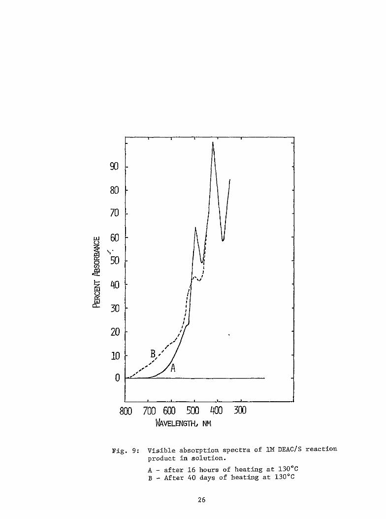
Longer-chain polysulfides (Sn-2 n gt 4) were found to react with DMAC or DEAC at 1300C Both of these amides produced gases the amount of which increased with increasing heating time A plot of the amount of gases produced versus heating time (days) is shown in Figure 6 Vapor phase infrashyred spectrum (Fig 7) indicated that the gases were the same from both of the amides and were identified as containing mostly carbon oxysulfide COS The visible spectra of these solutions also showed major changes after the heating This is illustrated in Figure 8 for a solution of Na2S8 in DMAC After heating for 21 days at 1300C the absorption peak at 520 nm characshyteristic of long chain polysulfides found in freshly prepared solution has considerably decreased in intensity The spectral properties of the solushytion before and after the heating suggest that during heating So present in solution in equilibrium with polysulfides reacts gradually with the amides to produce carbon oxysulfide and polysulfides of shorter chain lengths It appears thus that the reactive species in these solutions is elemental S The stability tests at 1300C on mixtures of S and DMAC or DEAC seem to support this Elemental S is insoluble in NN-dimethylacetamide or in NN-diethylacetamide at room temperature However when a mixture of S and either of these amides is heated to 130C anorange-yellow solution is formed No gas is formed from this reaction mixture in 16 hr at this tem perature The visible spectra of these solutions Figs 9 and 10 show broad absorptions with a peak at 437 nm for the DMAC-sulfur reaction proshyduct and two peaks at 500 nm and 425 nm for the DEAC-sulfur reaction product
The solvents alone show no absorptions above 300 nm after heating for the same period of time
21
100
90
80
70
C- 60
00 f50 I g
~L1
(n30
20
700 600 500 400 300 PAVELENGTH NM
Fig 5 Visible spectrum of a solution of Na2Sn in DMAC after heating for 21 days at 1300 C
22
10
0
0
01 05 L
n 1
Fig 6
TTl
L
A- - ACN2 n sl- in
5 10 15 20 NUMBER OF DAYS HEATED AT 130WC
A plot of the amount of gas produced vs heating time for amideNa2S solutions
A - ACNa2Sn solution n = 8 B - DMAGNa2S2 solution n = 8 C - NMACNa2Sn solution n = 6 D - DBACNa2Sn solution n =8
23
w
2 5
T7gt I-~
3
~
35 4 45
-I -FW i ItJLVI ~ 4ttlt
5
I Fl
4iI
-6
WAVELENGTH IN MICRONS
55 6 65 7 75
IdIll III I
4-
8 9 10 11
f fli IIIII--
TIU j iu
-
12
1 l0
14
P t
16
41
18 20 25 30
ill1l -1
T
7
40
0
P64V
tI
I jI 2gtV R
7
-i J
0 1 f 2k
1 7
qBb IT
7-~gt
-4 IL~ d2l JJi~
50
C
TWAVU EE0cnr
Fig 7 Vapor phase infrared spectrum of gases from DMACNa2S8 130deg C
solution after 21 days of heating at
100
90
80
70 -I
ou60 - It C
I B g I
4 IV II
40U)30-I ~AJ It
20I
10 IwI
700 600 500 400 300
WAVELEN M3H NM
Fig 8 Visible spectra of solutions of Na2S8 in DMAC B - After heating for 12 days at 130C C - After heating for 21 days at 130C
25
90
80
70
50
~30
10 B- I
A0 0 -shy
800 700 600 500 400 300 WVELENGTHJ NM
Fig 9 Visible absorption spectra of iN DEACS reaction
product in solution
A - after 16 hours of heating at 1300C
B - After 40 days of heating at 130C
26
100
90
80
70 itII
9 50 w 0 I
40II 4U
rh 30
20
10 A YB
0 shy
800700 600500 400300 WAVELENGTHi NM
Fig 10 Visible absorption spectra of the DMACS
reaction product in solution
A - after 16 hours of heating at 13000
B - After 21 days of heating at 1300
27
Further heating of these solutions produce gases the amount of which increases with increasing heating time Some changes are also observed in the visible spectrum of the solution although the gross features of the spectra are maintained Vapor phase infrared (Fig 11) and mass (Fig 12) spectral data proved that the gases were a mixture of carbon oxysulfide (COS) and carbon disulfide (CS2) About 75 of the mixture was carbon oxysulfide It was found that the reaction of each of the four amides with S under the present reaction conditions produces a similar mixture of volatile products of COS and CS2 The evidence that COS and CS2 are proshyduced considerably after the initial reaction with S suggests that in all cases these gases are secondary reaction products It appears that elemental sulfur reacts initially with the amides to produce long chain sulfur conshytaining products which on continued heating decomposes to give COS and CS2 as shown in Equations 14 and 15
CH3 CON(CH3)2 + nS 1 - CH3COSnN(CH3)2 (14)
I
CH3COSnN(CH3)2 GA (15)CH3SnIN(CH3)2 + COS
II
The various physical properties of the solution products are also consistent with the formation of the polysulfides I and II For example the visible spectrum resembles that of alkali metal polysulfides in non-aqueous solshyvents (10) The infrared spectrum of the orange solution from DMAc and S exhibited an absorption at 1135 cm-i which is in the region of C-S stretching vibrations The IH NMR spectrum of this solution exhibited a complex pattern Nevertheless the presence of new -N(CH3)2 resonances centered at 29 ppm and a new-COCH 3 or -SCH 3 resonance at 151 ppm are also consistent with the structures I and II
The formation of the same gas products from the reactions of both elemental S and Na2Sn n gt 4 suggests a possible explanation for the observed reaction with Na2Sn n gt 4 as follows
A variety of equilibria involving S chains and elemental S are usually present in solutions of alkali metal polysulfides in nonaqueous solvents There is evidence from spectroscopic and electrochemical studies (17) for the existence of equilibrium of the type 16 in solutions of alkali metal polysulfides in solvents such as dimethylsulfoxide (DMSO) or tetrahydrofuran(THF)
S + xS0 (16) n n-x
28
J5
-T F 3 4 45
77 5
Is
WAVELENGTH IN MICRONS
55 6 65 7 75 a 9
iq[ P ill U
14 111 I
10 1I
-shy
12 14 16 18 20 25 30
1
40
lo
7-I- r shy 2 -
1
_ IC4
sil T sit
Y l Is
i t j _t __ 11t i ill
+ 411-T
r 3000 2000 800 3600 400
WAVENUMBER cm -1
200 3000 800 600 500 400 300
Fig 11 Vapor phase infrared spectrum of the gases from DMACIS solution after 21 days of heating
at 13000
9 0 _ _ _
70 shy
~60 I_
30 IoIi I
20 -- shy
10 - shy
0 10 20 30 40 50 60 70 80 90 100 WE
Fig 12 Mass spectrum of the gases from DMACS solution after 21 days of heating at 130C
30
The solution properties of Sn-2 in DMAC resemble strongly those of Sn-2 in DMSO (17) It appears that when a solution of Sn-2 n gt 4 in DMAC is heated the neutral S present in equilibrium reacts with the amide to form I This reaction shifts equilibrium 3 to the right until all the Sn-2 is converted to S4- 2 Further dissociation of S4-2 is not observed probably because of a unique stabilization of S4- 2 in this solvent Spectral data suggest that S4- 2 is strongly dissociated in DMAC to form S3- according to Equation 17
2S4-2 S2- 2S3-
In general it is seen that basic solvents such as DMAC DEAC hexamethyl -phosphoramide (EMP) or DMSO promotes the dissociation of S4 2 in the manner
shown in Equation 17 The rather high concentration of the anion radical in these solvents may indicate a unique stabilization accorded to it through solvent coordination A common feature of all these solvents is that they possess electron-rich structural units such as C=0 P=O or S=0 It appears that the solvent-S3- coordination occurs through these functional groups and may involve a five-membered ring structure III
0P 5
SS III
-Solutions of Sn 2 n gt 4 in acetamide or N-methylacetamide also behave in a similar manner to the N-dialkyl substituted amides except that the acetamide solution is much less stable Some H2S is also produced from these solutions The formation of H2S may be explained on the basis of Equations 8-11
o Summary and Conclusion of Stability Studies
The aliphatic amides investigated in this program are thermally stable for long periods of time in the temperature range of 100 to 1500C However their Na sulfide solutions show varying degrees of reactivity which depend both on the nature of the sulfide and the nature of the amide The overall stability trend is CH3CON(CH3)2 0 CH3CON(C2D5)2 gt CH3CONH(CH 3)2 CH3CONH2 It is also found that with the dialkyl substituted amides the reaction is limited to Na2Sn with n gt 4 Thus of the four solvents the most suitable ones are CH3CON(CH3)2 and CH3CON(C2H5)2 With these two solvents it might be possible to achieve a relatively stable cathode by suitably controlling the charging limit of the battery to the formation of a medium chain polysulfide such as S4- 2
31
3 Sodium-Sulfur Cell Studies with CH3CONR2Na2Sn Cathodes
a Experimental Results
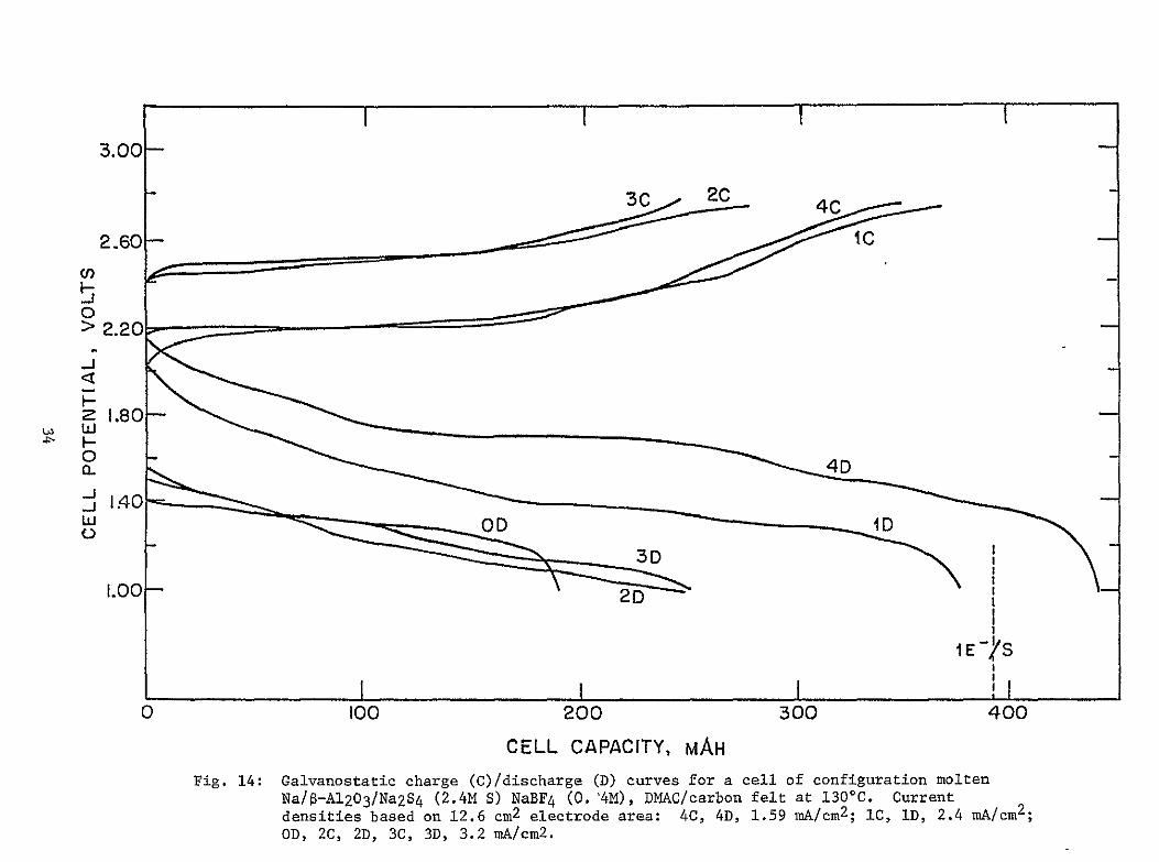
In a previous program (10) we studied the cycling behavior of the DMACNa2Sn cathode incorporated in a cell of configuration shown in Figure 13 During short-term cycling studies this cell exhibited good reversibility between voltage limits of 100 and 270V Typical discharge charge curves are shown in Figure 14 The average cathode cycling stoichioshymetry at 1300 C corresponded to
25S S -2 + 8e- (18) 52 10
No elemental S was formed during cell charging but only long chain soluble polysulfides The major system limitation was found to be the termination of discharge (sharp voltage cutoff to 10V) in the vicinity of a polysulfide composition of S2- 2 The major reasons for this appeared to be the very low solubilities of the lower order polysulfides and the consequent choking of the carbon felt current collector by the precipitated Na sulfide(s)
The carbon current collector in the above cells was fabricated from graphite felt (Union Carbide WDF felt) This has a porosity of only b5(1) The Teflon-bonded carbon electrode used in Lisoluble S cells (17) or in LiSOC12 cells (18) has a porosity in the neighborhood of 80 The effect of the higher porosity Teflon-bonded carbon electrode on the discharge capacity of the DMACNa2Sn cathode was assessed in the present study using a cell similar to the one shown in Figure 13 except that the graphite felt electrode was replaced with a Teflon-bonded carbon electrode The latter electrode 6 cm x 36 cm x 0096 cm was fabricated by Teflon-bonding 06g Shawinigan 50 compressed carbon black on an expanded stainless steel grid (Exmet Corp) The electrode was wound around the O-A1203 tube and when placed in the cell it was firmly positioned by pressure contacting the walls of the two compartments The cell was filled with 7 ml of 4M S as Na2S4 in DMAC075M NaI electrolyte The open circuit potential of the cell was 182V as found previously with the graphite felt electrode and the cell exhibited a resistance of 70 at 1300 C The cell was galvanshyostatically discharged and charged withih the limits of 100 and 240 volts A typical chargedischarge curve is shown in Figure 15 The open circuit potential of the cell measured at the end of discharge was 123V This
-2suggests that the discharge of Na2Sn to a composition below S2 was achieved with the Teflon-bonded carbon electrode as opposed to a discharge
-only to S2 2 with graphite felt In the latter case the OCV of the cell at the end of discharge corresponding to the polysulfide composition of
S2 2 was 176V The present cell cycled five times and the average
32
A
PT-WIRE TUNGSTEN WIRE ANODE
CATHODE
TEFLON 0-RING
VACUUM-STOPCOCK
S-JOINT
C
)9-A1203-GLASS SEAL
-G-A12 03
-PYREX GLASS RESERVOIR FOR NA2SX SOLUTION
-NA
-GRAPHITE FELT
Fig 13 High temperature electrolytic cell having a 6-A1203 separator
33
300 -
2-60-
3-C 2C 4C I C
0gt 220
U3 W
0
180shy
1O00 3D
2D
i E- S
0
Fig 14
100 200 300 400
CELL CAPACITY MAH
Galvanostatic charge (C)discharge (D) curves for a cell of configuration molten NaS-A1203Na2S4 (24M S) NaBF4 (04M) DMACcarbon felt at 1300C Current densities based on 126 cm2 electrode area 4C 4D 159 mAcm2 IC ID 24 mAcm2 OD 2C 2D 3C 3D 32 mAcm 2
3C25
10
100 200 300 40 500
Fig 15 The third discharge (3C) and fourth discharge (4D) curves for a cell liquid Naa-Al203Na2S4 (4M S) 075M NaI DMACTeflon-bonded C electrode at 130C Current = 20 mA current density = 2 mAcm2 The cell was tested galvanostatically
charge utilization in discharge was just below le-S However the lower S utilization might be due to the unoptimized current collector especially with respect to the solution to current collector volume ratio Since we know that the primary self-discharge reaction is the reaction of the amide with elemental S which would occur in significant amounts only when the polysulfide composition is gt4 it might be possible to achieve long cycle life as well as good S utilization with an optimized cathode structure consisting of a solution of Na2Sn in DMAC and a high porosity carbon such as a Teflon-bonded carbon current collector Note that the reversible reaction
-$4 2 + 6e- t 4s - 2 (19)
involves 15e-S and the loss of O03e-S by restricting the charging
limit to S42 is minor compared with the possible gain in cycle life
The cycling behavior of a NaS cell with a DEACNa2SnNaI cathode was also evaluated A Teflon-bonded carbon electrode similar to the one discussed above was used The cell initially contained 6 ml of a 2M S solution as Na2S4 in DEAC0SM NaT electrolyte The OCV of the cell was initially 184V similar to that observed with a DMACNa2S4 cathode The cell exhibited a resistance at 1300C of 15S2 The cell was cycled at the various constant currents of 10 20 and 30 mA corresponding to current densities of 1 2 and 3 mAcm 2 Cycling limits of 1OV and 27V were used The dischargecharge curves are shown in Figures 16 17 and 18 The cell exhibited good reversibility behavior although the discharge capacity did show a tendency to decrease with increasing cycle number especially after the 5th discharge Much of this loss may be attributed to the self-discharge reaction between DEAC and elemental S In this cell we made no attempt to restrict the charging limit to an intermediate size
2polysulfide chain such as S4 - the highest charge composition with minimal amounts of elemental sulfur in equilibrium
Summary and Discussion of Cell Cycling Studies
The cell cycling studies indicate that DMAC and DEAC exhibit analogous behavior with respect to their solvent properties for the dissolved S cathode The discharge capacities obtainable practically for cathodes consisting of solutions of Na2Sn in these two solvents appear to be strongly dependent on the porosity of the current collector the more porous the current collector the greater the depth of discharge This results from the fact that with a highly porous current collector it would be possible to store larger amounts of the insoluble di- and monosodium sulfides on the electrodes as is done in the case of LiSOCI2 cell (18) There is a slow self-discharge reaction in these cathode systems However it appears that this can be minimized greatly by restricting the charging
36
30 1 iC
2C
25
2 20
15
10 2D
k-s 50 100 a5 200 250 3M 350
Fig 16 Galvanostatic dischargecharge curves for a cell liquid NaV-A1203Na2S4 (2M4 8) 05M4 NaI DEACTeflon-bonded C electrode at 130C Current 10 mA current density 1 mAcm2= = Cell was discharged first 1D The charge curve 10C represents the last charge half cycle after the cycles shown in Figs 17 and 18
30 I I | I I
25
20shy
0 15 shy10
10
IT-SII I I I I I
50 I0 L 200 250 300 350 M4H
Fig 17 The third discharge (3D) third charge (3C) and fourth discharge (4D) curves for the cell shown in Fig 16 Current = 20 mA current density = 2 mAcm2
30 I I
9C
25
20
1 15
10 lOD
IC
50 i0 150 200 250 300 350 MA
Fig 18 Cycles five through ten of the cell shown in Fig 16 The 7th and 8th charge and 8th and 29th discharge curves are not shown Current = 30 mA current density = 3 mAcm
limit of the battery to a medium size polysulfide such as S4-2 Comparison with the high temperature battery (1) shows that for an equivalent energy density of 60 Whrlb it is necessary to achieve a solubility (as Na2S0) of -l3M if the charged cathode is to be in solution and if a complete
-2reduction to S is obtained As we have seen with a highly porous cathode it might not be necessary to achieve this much solubility for Sn-2 The insoluble materials could be stored on the cathode current collector itself To date only lower-rate cycling has been achieved mostly due to ohmic drops in thick non-state-of-the-art $-A1203 tubes
B Sodium-Sulfur Cell with a 13 Cyclohexanediol (CHD)Na2Sn Cathode
Alcohols in general are unstable in the presence of Na2Sn at temshyperatures gtl00C However it was pointed out to us by Drs W L Fielder and J Singer of NASA-Lewis that 13 cyclohexanediol (CHD) C6HIO2 was an exception Long-term stability tests carried out as in the case of the amideNa2Sn solutions indicated that CHDNa2S or CHDNa2Sn n = 4 8 were stable at 1300C at least for 21 days The higher stability of this diol may be associated with the cyclohexane structure Two cells were studied using this solvent They were (i) cell in which the initial catholyte was CHDNa2S05M NaBr (ii) cell in which the initial catholyte was CHDNa2S405M NaBr
1 Cell with CHDNa2 S0SM NaBr Solution as the Initial Catholyte
The cell was assembled as described earlier Since Na2S is soluble in CHD to the extent of about IM the cell was initially charged with llg of Na2S and 7 ml of CHD05N NaBr electrolyte was then added to make the solution the equivalent of M in Na2S The Teflon-bonded carbon electrode used in the cathode compart $nt was identical to the one described before The OCV of the cell initiall was 138V The cell exhibited a resistance at 130C of 230 The cell wp cycled at 10 mA or about 1 mAcm2 The chargedischarge curves are shown in Figure 19 The first charge curve 1C to 27 volt corresponds to uO33 e-S Only about 17 of Na2S was utilized in the charging process It appears that Na2S was poorly distributed on the carbon electrode so that most of it was not available for the cell process The first discharge curve ID commenced at 16V but in u20 iAh the cell polarized to 11V and further discharged proceeded at rvlIV This disshycharge voltage is considerably lower than for the NaDMACNa2Sn cells The second charge corresponded to 0e-S Evidently more Na2S was available for the charging process The second discharge curve 2D proceeded with voltage fluctuations and the cell reached the 1V limit in about 4 hours or 40 mAh The third charge curve 3C proceeded smoothly but at a considerably higher voltage and after 34 mAh of charge the cell open circuited to the voltage of the current source The experiment was terminated
40
I 1
30 - 1
lt-4PE CELFAILED) 4I2 20
lI r2D I 10
00 L_L_
50 i00 150 200 250
Fig 19 Galvanostatic chargedischarge curves for a cell liquid NaS-A1203 Na2S (2M S) 05M NaBr CHDTeflon-bonded C at 1300 C Current = 10 mA Current density = 1 mAcm2
i
2 Cell with CHDNa2S405M Nal Solution as the Initial Catholyte
The cell initially contained 9 ml of a 2M S solution as Na2S4 in CHD 05M NaI electrolyte All the other features of the cells were similar to those in the cell with CHDINa2S as the initial catholyte The OCV of the cell at 130C was 183V and the cell exhibited a resistance of 25Q The resistance was twice that found for cells with DMACNa2Sn or DEACNa2Sn cathodes and having the same type of $-A120 3 tube The higher resistance was probably due to the higher viscosity of CHD The galvanostatic discharge and charge curves at 9 mA or 1 mAcm2 are shown in Figure 20 As observed previously the discharge begins at rvl6V but the cell polarizes immeshydiately to a plateau of 125V This initial polarization to the 125V plateau is more pronounced in the second discharge (2D) The first disshycharge proceeded for 194 mAh (04e-S) at which point a malfunction of the cycler caused the cell to charge The charge capacity to 27V was however much less than the previous discharge ie only 110 mAb (023e-S) The second discharge (2D) proceeded for 650 mAh After accounting for the charge utilization in the first cycle a charge equivalent to 640 mAh would be required to reduce the Na2Sn present at the beginning of 2D to Na2S The discharge capacity of 650 mAh thus corresponds to the reaction
4S - 2 S4 2 + 6e- (20)
This agreement as well as the fact that a le reduction of CHD would require 17 Ah charge indicate that the solvent is not reduced at potentials above IV Nevertheless the second charge (20) proceeded for only 124 Ah (025e-S) The third discharge was less than the second charge and the subsequent charge and discharge also showed the decreasing efficiency The cell could not be operated after the fourth cycle
The following conclusions may be drawin about the behavior of the CHDNa2Sn cathode
Na-S cells with CHDNa2Sn cathodes have relatively higher resistances probably due to the higher viscosity of CHD
The operating voltage of the cell is low
Na2Sn can be reduced to Na2S but the cathode exhibits poor reversibility
42
30
4C 3 IC 2C
25
20
215
10 4D 3D
II I I-SI I
]DO 200306MAH
400 500 600 700
Fig 20 Galvanostatic dischargecharge curves for the cell liquid NaS-A1203CHD 05M Nal 2M S as Na2S4 (9 ml) Teflon-bonded C at 130C Current = 9 mA current density = I mAcm 2 The cell was discharged first
III THE Na-TRANSITION METAL SULFIDE BATTERY
A preliminary evaluation of transition metal disulfides as possible
cathode materials for the Na battery was done using the disulfides TiS 2
and TaS2 They were separately evaluated in a cell of the configuration
Liquid NaIS-A1203MS2 DMAC NaT
The DMACNaI solution served as the Na+-ion conducting electrolyte The
experiments were conducted at 1300C
A Preparation and Characterization of the Disulfides
1 Titanium Disulfide TiS2
Titanium disulfide TiS2 was prepared by the direct reaction of
stoichiometric amounts of Ti metal and S vapor at 750 0C The reaction - 3
was carried out in a sealed evacuated (10 torr) quartz tube under a temshy
perature gradient achieved in a tube furnace
In a preparation 7g Ti metal powder (100 mesh) and 96g S (Ventron
crystals 9999) were introduced into either end of a thick-walled quartz
tube of 25 mm OD and 57 cm long The tube was evacuated (10-3 torr) and
sealed off It was then introduced into a three-zoned furnace and heated with the temperature profile shown in Table 7 After heating the tube
was allowed to cool to room temperature and the TiS2 was collected It
was a dark green solid with a distinct yellow metallic luster when spread
into the form of a thin film The X-ray diffraction pattern for a sample of TiS 2 prepared by the same procedure as is shown in Table 8 The experishy
mental values are in good agreement with those calculated for hexagonal TiS 2
The titanium content of the sulfide was analyzed as the oxide according to the reaction
TiS 2 700C TiO2 + 2S 2 (21)2 0
In this procedure 05235g of TiS 2 contained in a preweighed alumina
crucible was ignited in air at 700 0 C until all the sulfide was converted to the oxide The oxide weighed 037 85g which was equivalent to 434 Ti in the disulfide sample The formula of the disulfide was calculated to be
Ti102S2
44
TABLE 7
TEMPERATURE PROFILE FOR THE PREPARATION OF TiS2 FROM Ti and S
Zone A Time (hr) (15 cm long)
at Each Temp (Titanium Metal)
1 500
25 550
19 600
29 650
20 700
27 750
Temperature OC
Zone B (30 cm long)
Zone C (15 cm long)
(Sulfur)
500 400
550 400
600 400
650 400
700 400
750 600
45
TABLE 8
X-RAY DIFFRACTION DATA CALCULATED FOR HEXAGONAL TiS2 AND OBSERVED LINES OF SAMPLES PREPARED BY
THE PRESENT PROCEDURE
Calculated Experimental
26lt Intensity 20lt Intensity
156 500 not done 342 1000 344 1000 - 398 149
441 450 444 505 - - 480 75
539 250 540 333 564 80 566 118
575 160 579 204 653 100 654 268 721 80 723 129 - 750 53
895 80 898 225 897 100 shy
46
2 Tantalum Disulfide TaS2
The tantalum disulfide was purchased from Cerac Inc Milwaukee Wisconsin (Catalog No T-1018) Its X-ray diffraction data according to the manufacture matched the pattern for hexagonal TaS2 We analyzed the Ta content of the disulfide as the oxide Ta2O5 using the reaction
2TaS 2 + 6 02 7000C Ta205 + 4S02 (22)
In the analysis 06051g TaS 2 gave 05482g Ta205 which corresponded to 742 Ta in the disulfide sample The formula of the disulfide was calshyculated to be Tal01S2
B Stability Characteristics of Metal SulfideAmide Mixtures
The long term stability characteristics of dimethylacetamide (DMAC) diethylacetamide (DEAC) or their NaI solutions in the presence of TiS2 at 1300C were evaluated by the sealed tube technique Titanium disulfide was insoluble in these amides both at room temperature and at 1300C The tests were performed with mixtures of the amide or its NaI solution conshytaining an excess of undissolved TiS2 The various test mixtures and the results are shown in Table 9 No gases were produced from any of these mixtures even after 43 days of heating at 1300C After the heating the liquid was analyzed by UV-visible and infrared spectroscopy The liquid from each of the test mixtures exhibited a weak but broad absorption beginning at 500 nm and tailing off into the UV This absorption pattern resembled that of the reaction products of S with the amides described earlier and it might be due to minor products resulting from the reaction of unreacted S in the TiS2 with the amides
The results seemed to indicate that the overall stability of the amides in the presence of the disulfides was acceptable However it should be noted that since the amides are basic solvents their intercalation with the metal chalcogenide is possible This was not investigated
C Electrochemical Evaluation of Transition Metal Disulfides
1 Titanium Disulfide as the Cathode
Preparation of Pressed Electrodes
A mixture of TiS2 and Teflon powder (9010 wo) was intimately mixed with a mortar and pestle for b20 minutes The cathode mix was bonded
See Powder Diffraction File No 2-0137
47
TABLE 9
STABILITY TEST DATA FOR AMIDETiS 2 MIXTURES AT 1300 C
Tube No Reactants
A 047g TiS 2 2 ml DMAC
B 049g TiS 2 031g Nal
42 ml DMAC CO
C 049g TiS 2 2 ml DEAC
D 046g TiS2 031g NaI 2 ml DEAC
No of Days at 130
43
mmoles of Gas
no gas
43 no gas
43 no gas
43 no gas
Comments
light brown liquid over dark grey powder
light green liquid over dark grey powder
orange-red liquid over dark grey powder
orange-red liquid over dark grey powder
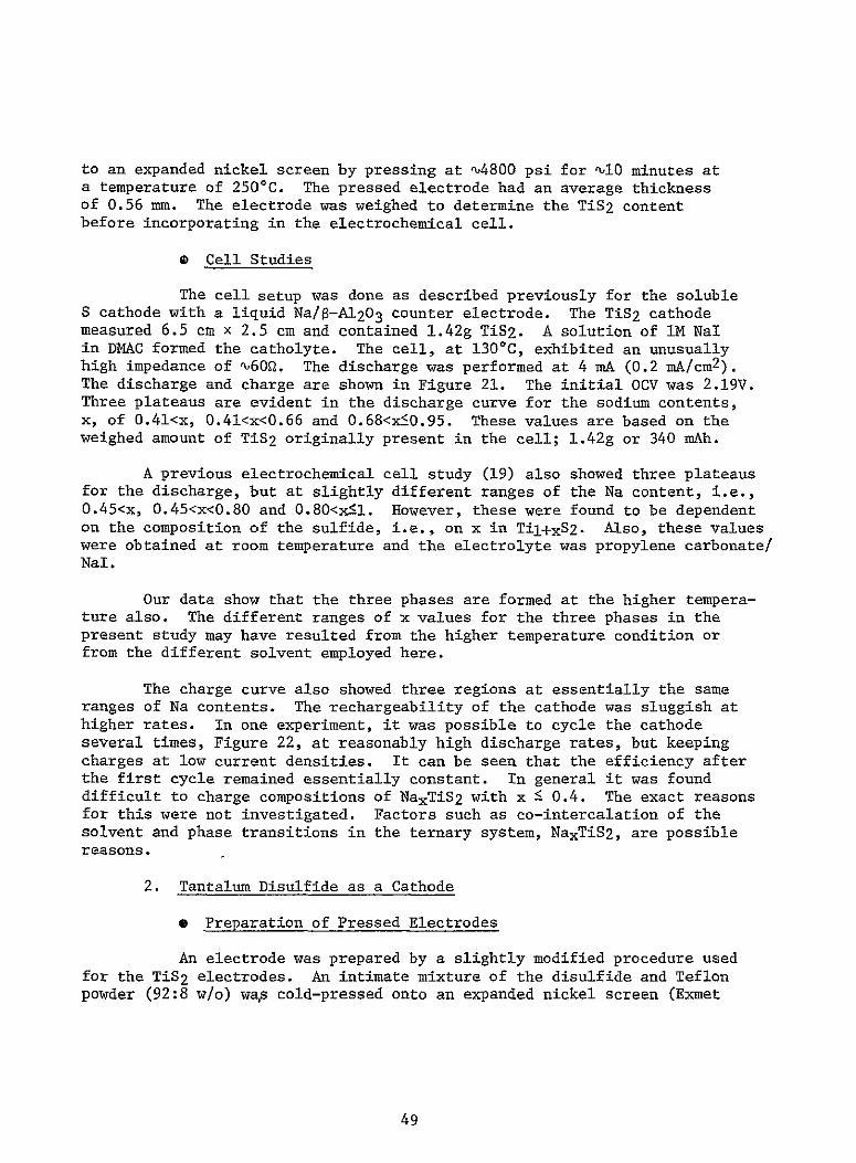
to an expanded nickel screen by pressing at 4800 psi for 10 minutes at a temperature of 250C The pressed electrode had an average thickness of 056 mm The electrode was weighed to determine the TiS2 content before incorporating in the electrochemical cell
Cell Studies0
The cell setup was done as described previously for the soluble S cathode with a liquid Na0-A1203 counter electrode The TiS 2 cathode measured 65 cm x 25 cm and contained 142g TiS2 A solution of IM Nal in DMAC formed the catholyte The cell at 1300C exhibited an unusually high impedance of u60Q The discharge was performed at 4 mA (02 mAcm2) The discharge and charge are shown in Figure 21 The initial OCV was 219V Three plateaus are evident in the discharge curve for the sodium contents x of 041ltx 041ltxlt066 and 068ltx5095 These values are based on the weighed amount of TiS2 originally present in the cell 142g or 340 mAh
A previous electrochemical cell study (19) also showed three plateaus for the discharge but at slightly different ranges of the Na content ie 04 5ltx 045ltxlt080 and 080ltx-ltl However these were found to be dependent on the composition of the sulfide ie on x in Til+xS2 Also these values were obtained at room temperature and the electrolyte was propylene carbonate NaI
Our data show that the three phases are formed at the higher temperashyture also The different ranges of x values for the three phases in the present study may have resulted from the higher temperature condition or from the different solvent employed here
The charge curve also showed three regions at essentially the same ranges of Na contents The rechargeability of the cathode was sluggish at higher rates In one experiment it was possible to cycle the cathode several times Figure 22 at reasonably high discharge rates but keeping charges at low current densities It can be seen that the efficiency after the first cycle remained essentially constant In general it was found difficult to charge compositions of NaxTiS2 with x S 04 The exact reasons for this were not investigated Factors such as co-intercalation of the solvent and phase transitions in the ternary system NaxTiS2 are possible reasons
2 Tantalum Disulfide as a Cathode
Preparation of Pressed Electrodes
An electrode was prepared by a slightly modified procedure used for the TiS 2 electrodes An intimate mixture of the disulfide and Teflon powder (928 wo) was cold-pressed onto an expanded nickel screen (Exmet
49
DEGREE OF INTERCALATION (x)
01 02 03 04 05 06 07 08 09 10 i i I I I I p
30
C
C 2 INITIAL OCV 219V CHARGE
a 20
CD
-LJ
15 - DISCHARGE FNAL 0CV
--- 125V
10
50 100 150 200 250 300 350 MAH
Fig 21 The dischargecharge curves for the cell liquid Na8-A1203DMAC (IM Nal) TiS2 at 1300C Current= 4 mA current density = 02 mAcm 2
DEGREE OF INTERCALATION (X)
02 04 06 08 p IIII
25
CCl
D5 4 D2 Dl
100
20 40 60 80 1020 140 mAh
Fig 22 Galvanostatic dischargecharge curves for the cell liquid Na -AI20BDXAC (lM NaI) TiS2 at 130C Dl thru D-5 are discharge curves Current = 20 M (u4 mAm 2 of 8-A1203) C1 thru C5 are charge curves Current = 5 mA or (uimAcm2 of 8-A1203)
Corp 5 Ni 5 - 50) at 5600 psi for t6 minutes The pressed electrode was then sintered in an argon atmosphere at 3000 C for half an hour We also prepared electrodes with NaTaS2 In this case the cathode was coldshypressed but no sintering was done afterwards
Cell Studies
Two kinds of experiments were carried out (i) initial discharge and subsequent cycling of the fully charged cathode TaS2 (ii) initial charge and subsequent cycling of the fully discharged cathode NaTaS2 The NaTaS2 was prepared chemically from Na naphthalide and TaS2 in tetrahydroshyfuran as described later
Tests with the TaS2 Cathode The cell utilized 1M NaIl
DMAC electrolyte A plot of the discharge potential (volts) vs the degree of Na intercalation (mole Namole TaS2) is shown in Figure 23 (curve A) The cell EMPs corresponding to the various degrees of Na intershycalation are shown in curve B Figure 23 Both of these curves show fairly linear transitions to lower potentials as the amount of intercalated Na is increased from zero to one At a discharge cutoff voltage of 100V only 08 mole of Na per mole of TaS2 was intercalated The EMF corresponding to this composition was 120V The EMF value corresponding to the fully intershycalated compound NaTaS2 was obtained from a cell incorporated with this material initially as the cathode The EMF was 097V at 1300C It thus appears that in order to achieve full intercalation of the TaS2 lattice the lower limit of the operating cell voltage has to be below 1OOV when the electrolyte is DACNaI The EMF-composition curve for the NaxTaS2 ternary system for values of x from zer6 to one in DMACNaT at 130degC constructed from the two sets of data is shown in Figure 23 (curve B)
The EMF-composition curve for the NaxTaS2 system is different from that observed with the NaxTiS2 ternary The present data for NaxTaS2 are in agreement with a previous study (20) on TaS2 at room temperature using PCNal electrolyte (see also inset in Figure 23) In that study the EMF-composition data along with the X-ray results indicated a single phase ternary system for NaxTaS2 for all values of x 0ltxltl The present data suggest the formation of a single phase ternary system also in the DMACNaI electrolyte at 130C The EMF-composition curve does show some deviations from linearity at low and high x values This in the absence of X-ray data may be attributed to the different solvent employed here The experimental data in the previous study also showed this behavior at low x values but X-ray revealed only one phase
Tests with NaTaS2 Cathode The fully Na intercalated disulfide
was prepared according to the reactions
52
DEGREE OF INTERCALATION (x)
02 04 016 08 10 26 0 T- 300Kshy
24
22El ifiS) 20(
ID shy
00 02 04 06 08 10
~ 0COMPOSITION X- Na5TQ2
L Measured cell volt O rgie as a fu-nction of compositionH-
n TaSzat3O00degK
at
15OPEN CIRCUIT VOLTAGES
CELL VOLTAGES B
0 A c
20 40 60 80 im mAh
Fig 23 The galvanostatic discharge curve for the cell liquid Na0-A120 3DMAC (IM Nal)TaS2 at 1300C Curve A is the plot of cell potential vs degree of Na intershycalation Curve B is the plot of open-circuit voltage of the cell as a functionof Na intercalation C is the open-circuit voltage obtained with NaTaS2 as the cathode Current -10 mAor 120 mAcm2 of B-A1203 Inset is the data from Ref 3
THF Na + CoH8 H - Na+ C oH8
2N108S2TaS2 + Na+C H -NaTaS 2+o 010o8
In a preparation 2 61g (204 mmoles) of naphthalene and 047g (204 mmoles) of Na were mixed in v50 ml THF and stirred overnight at room temperature to obtain a dark green solution of the naphthalide anion radical The exact Na concentration of the solution was analyzed by treating an aliquot of the solution (2 ml) with an excess of standard HC1 and then back-titrating the unreacted HCl with a standard solution of NaOH using phenolphthalein as the indicator To 48 ml of the naphthalide solution 4g (163 mmoles) of TaS2 were added and the mixture was stirred for 2 days The NaxTaS2 product was filtered washed with THF and finally dried in vacuum The NaxTaS2 product was collected as a very shiny dark grey material The filtrate was analyzed for its Na content The composhysition of the intercalated material was calculated to be Nal05TaS2 The EMF value of 097V vs Na+Na for this material also suggests a composition with x very close to one This material was used for testing the rechargeshyability of the TaS2 cathode
Rechargeability of TaS2 Cathode The rechargeability of the cathode in DMACNaI electrolyte appeared to be kinetically limited as evishydenced by data from cells in which the cathode initially was either TaS2 or NaxTaS2 In general the efficiency of rechargeability increased with decreasing current density It was also found that the EMF-composition curve during charge showed considerable deviation from that during discharge for the same degree of Na intercalation Figure 24 The galvanostatic charge curves obtained from the two different initial cathode compositions however showed analogous voltage-composition behavior
The work carried out herein suggests that transition metal disulfides present good possibilities as cathode materials in moderate temperature Na batteries Further work should concentrate on a-search for suitable elecshytrolytes that can accommodate high rate battery operation and on selection of cathode materials with minimum phase transition A most important issue is the inter-relationship between phase changes during Na intercalation and the rechargeability of the cathode This needs to be systematically explored
54
DEGREE OF INTERCALATION
02 04 06 08 10
10 A C
20 40 60 80 mAh
100 M2 140
Fig 24 Galvanostatic dischargecharge curves A and B for the cell liquid Nala-A1203 DMAC (IM Nal) TaS2 at 130C Current = 10 mA (r-2 mAcm2 of -AI203) Curve is the charge curve for a cell with NaTaS2 initally in the cathode current (i0 mAcm2 of a-A1203)
C 5 mA
IV SUMMARY AND CONCLUSIONS
The feasibility of a moderate temperature Na battery having the configuration
Liquid Na A-Al203Dissolved Na2Sn or
transition metal disulfide
has been investigated The operating temperature of the battery is 1300C Two kinds of cathode were investigated (i) a soluble S cathode consisting of a solution of Na2Sn in an organic solvent and (ii) an insoluble S cathode
-consisting of a transition metal dichalcogenide in contact with a Na+-ionconducting electrolyte
A series of aliphatic amides was investigated in an attempt to find a suitable solvent for the soluble S cathode with special emphasis on long term stabilities in the presence of Na2Sn The dialkyl substituted amides were found to be the most stable They did show some reactivity during long term heating with Na2Snn gt 4 However isolation studies indicated that the reactive species in these solutions was the elemental sulfur present in equilibrium The stability studies also indicated that relatively longer cycle life could be obtained for the CH3CONR2Na2Sn cathode if the cell operation is limited to the cycling regime
$4-2 + 6e- - 4S-2 15e-S
Cell cycling studies using the solutions CH3CON(CH3)2Na2Sn or CH3CON(C2H5) 2 Na2Sn indicated that these cathodes were reversible and that the reduction of Sn-2 to S-2 could be achieved with a highly porous cathode current collector structure
The suitability of 13-cyclohexanediol as a solvent for the soluble S cathode was also investigated It was found that this solvent is stable with respect to Na2Sn for long periods of time and that it dissolves moderate amounts of Na2S However the electrochemical reversibility of 13-cyclohexanediolNa2Sn solutions was poor
A limited amount of study was carried out to determine the suitability of transition metal dichalcogenides as possible cathodes for the Na battery Our results of studies with TaS2 or TiS 2 indicated that the phase transitions during intercalation of Na into the transition metal dichalcogenides are strongly dependent on the structure of the dichalcogenide themselves In general transition metal disulfides present good possibilities as cathode materials for the moderate temperature Na battery
56
V REFERENCES
1 Annual Report on the Ford Sodium-Sulfur Battery Contract NSF-C805 (AER73-07199) July 1976
2 C Levine Proc 10th IECEC Meeting p 621 (1975)
3 J T Kummer and N Weber Auto Eng Cong Detroit Michigan SAE 670179 (1967)
4 N K Gupta and R P Tischer J Electrochem Soc 119 1003 (1972)
5 Y K Kas and P C Wagner J Electrochem Soc 123 623 (1976)
6 G L Holleck and J R Driscoll Electrochim Acta 22 647 (1977)
7 S P Mitoff and J B Bush Jr Proc 9th IECEC Meeting p 91 6 (1974)
8 J Werth et al ESB Inc Report on EPRI Research Project 109-2-1 June 1975
9 J Werth paper presented at Argonne National Laboratory Workshop on High Temperature Batteries March 1976
10 K M Abraham R D Rauh and S B Brummer Electrochim Acta 23 501 (1978)
11 D F Shriver The Manipulation of Air Sensitive Compounds (New York McGraw-Hill 1969)
12 J A Riddick and W B Bunngen in Organic Solvents (New York Wiley-Interscience 1970)
13 D S Reid and C A Vincent J Electroanal Chem 18 427 (1968)
14 W Blaedel and V Meloche Elementary Quantitative Analysis 2nd ed (Harper and Row 1963) p4 6 3
15 R Fritz and P Yamamura Anal Chem 27 9 (1955)
16 B Lux et al Chem Bev 101 2485 (1968)
17 S B Brummer et al Low Temperature LithiumSulfur Secondary Battery Annual Progress Report ERDA Contract No EY-76-C-02-2520 June 1977
57
18 D R Cogley and M J Turchan First Quarterly Report on Contract
DAAB07-74-C-0030 December 1973
19 D A Winn et al Mat Res Bull 11 449 (1976)
20 A S Nagelberg and W L Worrell Proceedings of the Symposium on Electrode Materials and Processes for Energy Conversion and Storage The Electrochemical Society p487 (1977)
58
DISTRIBUTION LIST
Dr Ted Beck Dr Morris Eisenberg Electrochemical Technology Corp Electrochimica Corp 3935 Leary NW 2485 Charleston Road Seattle WA 98107 Mountain View CA 94040
Dr Douglas Bennion Dr D Thomas Ferrell
Energy and Kinetics Department ESB Technology Center
School of Engineering amp Applied Science 19 West College Avenue
University of California Yardley PA 19067
Los Angeles CA 90024 Dr A Donald Galbraith
Mr William Botts Power Cell Program Office
Program Manager Lockheed Palo Alto Research Lab
Atomics International 3251 Hanover Street PO Box 309 Palo Alto CA 94304
Canoga Park CA 91304 Dr Jose Giner
Mr John Bush Giner Inc General Electric Corp 144 Moody Street
Research and Development Center Waltham MA 02154
PO Box 8 Schenectady NY 12301 Dr Gilbert Goodman
Globe-Union Inc Dr Alna Boruka Milwaukee WI 53201 Boruka Research Co 60 Chestnut Street Dr Robert Huggins Livingston NJ 07039 Stanford University
Center for Materials Studies
Dr Jack Brown Stanford CA 94305 Research Laboratory Westinghouse Electric Corp Mr Henry Jensen VP
1310 Beulah Road CampD Batteries Pittsburgh PA 15235 3042 Walton Road
Plymouth Meeting PA 19462
Dr Ralph Brodd Research Laboratories Dr Charles A Levine
Union Carbide Corp Dow Chemical Research Labs
Parma OH 44129 Walnut Creek Center 2800 Mitchell Drive
Mr Earl Carr Walnut Creek CA 94598
Eagle Picher Industries Inc Electronics Div Couples Dept Prof Prem Mahendroo
PO Box 47 Department of Physics Joplin MO 64801 Texas Christian University
Fort Worth TX 76129
Dr David Douglas Vice Pres Contract Research Dr John NewmanDr Charles Tobias
Gould Inc Department of Chemical Engineering
40 Gould Center University of California
Rolling Meadows IL 60008 Berkeley CA 94720
Dr A Skopp Director Advanced Energy System Laboratory Exxon Research amp Engineering Company PO Box 8 Linden NJ 07036
Dr Robert Selman Illinois Institute of Technology 3300 South Federal Chicago IL 60616
Dr S Weiner Ford Corp Chemical Engineering Department Scientific Research Staff 20000 Rotunda Drive Dearborn MI 48121
Mr Ralph Zito GEL Inc 1511 Peace Street Durham NC 27701
Catalyst Research Corp 1421 Clarkeview Road Baltimore MD 21209
Yardney Electric Corp 82 Mechanic Street Pawcatuck CT 02891
Energy Research Corporation 3 Great Pasture Road Danbury CT 06810
Dr Ernest Yeager Case-Western Reserve University Electrochemistry Research Lab Cleveland OH 44106
Giovanni Caprioglio General Atomic Co PO Box 81608 San Diego CA 93128
Commander Naval Sea Systems Command Department of the Navy Arlington VA 20362
Defense Documentation Center Cameron Station - Bldg 5 Alexandria VA 22314
National Aeronautics amp Space Admin Washington DC 20546 Attn RPP
Command Officer US Army Electronics RampD Labs
Fort Monmouth NJ 07703 Attn Mr David Linden (DRSEL-TL-P)
Frank J Seiler Research Lab (AFSCO) FJSRL-WC USAF Academy CO 80840 Attn Capt Erbacher
Harry Diamond Laboratories Chief Power Supply Branch 2800 Powder Mill Road Adelpha MD 20783 Attn Mr A A Benerley
Flight Vehicle Power Branch Air Force Aero Propulsion Lab Wright-Patterson AFB OH 45433
Institute for Defense Analysis RampE Support Division 400 Army-Navy Drive Arlington VA 22202 Attn Mr R Hamilton
Office of Naval Research (Code 472)
800 North Quincy Street Arlington VA 22217 Attn Dr George A Neece
Naval Ship Engineering Center Center Building Prince Georges Center Hyattsville MD 20783 Attn Mr A Himy Code 6157D
NASA Scientific amp Technical (30 copies) Information Facility
BaltimoreWashington Intl Airport PO Box 8757
Maryland 21240
Institute of Gas Technology 3424 S State Street IIT Center Chicago IL 60616 Attn K Blurton
Dr Arthur Fleischer 466 South Center Street Orange NJ 07050
Furukawa Battery Co Ltd No 246 Z-Chome Hoshakawa-Cho Hodogaya Yokohama Japan Attn K Shimizu
Gates Energy Products Inc 999 S Broadway Denver CO 80217 Attn E Seo
General Dynamics Convair Aerospace Division Dept 623-2 PO Box 80847 San Diego CA 92138 Attn R P Mikkelson
Battery Business Dept General Electric Company PO Box 114 Gainesville FL 32602 Attn M Kronenberg
General Electric Company Space Systems Room M-2700 PO Box 8555 Philadelphia PA 19101 Attn K L Hanson
General Electric Company 777 14th Street NW Washington DC 20005 Attn D F Schmidt
General Motors Research Labs Electrochemistry Department Warren MI 48090
Attn R G Gunther
General Motors Research Labs Electrochemistry Department Warren MI 48090 Attn E J Cairns
Globe-Union Inc Corporate Applied Research
5757 North Green Bay Avenue Milwaukee WI 53201 Attn W L Towle
Grumman Aerospace Corp OAO Project Plant 35 Bethpage Long Island NY 11714 Attn S J Gaston
GampW H Corson Inc Plymouth Meeting PA 19462 Attn L J Minnick
Chrysler Corp Space Division Department 2730 PO Box 29200 New Orleans LA 70189 Attn C E Thomas
Communications Satellite Corporation Comsat Laboratories PO Box 115 Clarksburg MD 20734 Attn R Strauss
Delco Remy Division General Motors Corp 2401 Columbus Avenue Anderson IN 46011 Attn J A Keralla
E I DuPont de Nemours amp Co Engineering Materials Lab Building 304 Wilmington DE 19898
Attn J M Williams
Dynatech Corp 17 Tudor Street Cambridge MA 02139
Attn R L Wentworth
Exxon Research amp Engineering Company Government Research Lab
PO Box 8 Linden NJ 07036 Attn L Berkowitz
ESB Inc Box 6266 Cleveland OH 44101 Attn G Hobbib
EST Inc Ray-O-Vac 630 Forward Drive Madison WI 73611 Attn R J Dawson Project Mgr
Electrochemical amp Water Desal Technology
13401 Kootenay Drive Santa Ana CA 92705
Attn C Berger
Gulton Battery Corp 212 Durham Avenue Metuchen NJ 08840 Attn E Kantner
Hughes Aircraft Corp Centinda Avenue amp Teale Street Culver City CA 90230 Attn T V Carvey
Hughes Research Labs 3011 Malibu Canyon Road
Malibu CA 90265 Attn H Sup Lim
Institute for Defense Analyses 400 Army-Navy Drive
Arlington VA 22202 Attn R Hamilton
International Nickel Co 1000 16th Street NW Washington DC 20036 Attn J R Hunt
Invention Talents Inc 1149 Chesapeake Avenue Columbus OH 43212 Attn J McCallum
Johns Hopkins University 8621 Georgia Avenue Silver Springs MD 20910 Attn R E Evans
Midwest Research Institute 425 Volker Boulevard Kansas City MO 64110 Attn Physical Science Lab
Johns-Manville RampD Center PO Box 159 Manville NJ 08835 Attn J S Parkinson
Kimberly-Clark Corp New Market Development Mgr Neenah WI 54956 Attn R T Carpenter
Leesona Moos Laboratories 333 Strawberry Field Road Warwick RI 02887 Attn A Moos
Mallory Battery Co So Broadway amp Sunnyside Lane Tarrytown NY 10591 Attn S J Angelovich
P R Mallory amp Co Inc Northwest Industrial Park Burlington MA 01803 Attn P Bro
Martin Marietta Corp Electronics Research Dept
PO Box 179 Denver CO 80201
McDonnell Douglas Astro Co 5301 Bolsa Avenue Huntington Beach CA 92647 Attn Library
McGraw Edison Co Edison Battery Division
PO Box 28 Bloomfield NJ 07003 Attn R C Chudacek
Melpar-Technical Information Center 7700 Arlington Blvd Falls Church VA 22046
Texas Instruments Inc 34 Forrest Street Attleboro MA 02703 Attn J W Ross
Monsanto Research Corp 1515 Nicholas Road Dayton OH 45407 Attn I 0 Salyer
North American Aviation Inc 12214 Lakewood Blvd Downey CA 90241 Attn B M Otzinger
North American Rockwell Autonetics Division PO Box 4192 Anaheim CA 92803 Attn R F Fogle (GA28)
North American Rockwell Corp Rocketdyne Division 6633 Canoga Avenue Canoga Park CA 91304 Attn Library
Philco-Ford Corp 3939 Fabian Way Palo Alto CA 94303 Attn D C Briggs
Power Information Center University City Science Center 3624 Science Center Philadelphia PA 19104
Rensselaer Polytechnic Institute Department of Chemistry Troy NY 12180 Attn G J Janz
Southwest Research Institute PO Drawer 28510 San Antonio TX 78228 Attn Library
Stanford Research Institute 333 Ravenswood Avenue Menlo Park CA 94025 Attn Librarian
Texas Instruments Inc PO Box 5936 Dallas TX 75222 Attn I Trachtenberg
TRW Systems Inc One Space Park (R-12094) Redondo Beach CA 90278 Attn H P Silverman
Union Carbide Corp Parma Laboratory PO Box 6116 Parma OH 44130 Attn Library
University of Maryland Dept of Mechnical Engineering College Park MD 20742 Attn F Morse
University of New Mexico Technology Applications Center Albuquerque NM 87131 Attn K E Cox
University of Pennsylvania 113 Towne Building Philadelphia PA 19104 Attn National Center for Energy
Management amp Power
BASF Wyandotte Corp Inorganic-Electrolytic RampD Syandotte MI 48192 Attn E Y Weissman
Englehard Industries Inc Menlo Park Edison NJ 08817 Attn J G Colin
Union Carbide Development Laboratory Library PO Box 6056 Cleveland OH 44101
Dr Judith H Ambrus WR-33 White Oak Laboratory Naval Surface Weapons Center Silver Springs MD 20910
NASA-Lewis Research Center 21000 Brookpard Road Cleveland OH 44135 Attn G M Ault MS 3-5
V Hlavin MS 3-10 Tech Util Office MS 7-3 L Rosenblum MS 49-5 C E May MS 106-1
J S Fordyce MS 302-1 D G Soltis MS 309-1 N T Musial MS 500-113 J E Bolander MS 500-312 Library MS 60-3 Report Control MS 5-5
National Aeronautics amp Space Admin Washington DC 20546 Attn L Holcomb Code RP-6
S V Manson Code NT P R Miller Code NE R LaRock Code NE Tech Util Office Code KT
NASA-Goddard Space Flight Center Greenbelt MD 20771 Attn F Ford (Code 7112)
G Halpert (Code 7112)
NASA-Langley Research Center Instrument Research Division Hampton VA 23365 Attn J E Zanks MS 488
NASA-George C Marshall Space Flight Center
Huntsville AL 35812 Attn C B Graff Code BO-I
NASA-Johnson Space Center Houston TX 77058 Attn J B Trout EP-5
NASA-Ames Research Center Moffett Field CA 94035 Attn J Ribenzer MS 24408
Jet Propulsion Laboratory 4800 Oak Grove Drive Pasadena CA 91103 Attn A A UchLyama MS 198-22
Douglas Barron Dept 120 Delco-Remy Division GMC 2401 Columbus Avenue
Anderson IN 46014
Commanding Officer US Army Mobility Equip RampD Center
Ft Belvoir VA 22060 Attn Energy Conv Research Div
(code SMEFB-EE)
Commanding Officer Picatinny Arsenal Code SMUPA-FR-S-P Dover NJ 07801 Attn M R Merriman
Office of Naval Research Arlington VA 22217 Attn Director Power Program
(Code 473)
Naval Ship RampD Center Annapolis MD 21402 Attn J H Harrison
(Code 2724)
Commanding Officer US Naval Ammunition Depot Crane IN 47522 Attn D G Miley
(Code QEWE)
US Naval Observatory 4301 Suitland Road Suitland MD 20390
Attn H E Ruskie (NISC-4321)
NAVAL Ordnance Laboratory Silver Springs MD 20910 Attn P D Cole
(Code 232)
Aero Propulsion Laboratory Wright-Patterson AFB OH 45433 Attn J E Cooper APIP-l
USAF Cambridge Research Laboratory L G Hanscom Field Bedford MA 01731 Attn E Raskin (Wing F) CREC
Rome Air Development Center EDS Griffiss APB NY 13440 Attn F J Mollura (TUGS)
National Science Foundation RANN Washington DC 20550
Attn L Topper
Aeronutronic Div of Philco Corp Technical Information Service Ford Road Newport Beach CA 92663
Advanced Battery Support Unit Building 429 AERE Harwell Didcot Berks OX 11 ORA England Attn Mr K T Taylor
Aerospace Corp PO Box 95085 Los Angeles CA 90045 Attn Library Acquisition Group
American University Chemistry Department Mass amp Nebraska Ayes NW Washington DC 20016 Attn R T Foley
Argonne National Laboratory Chemical Engineering Division 9700 South Cass Avenue Argonne Illinois 60439 Attn P Nelson
Arthur D Little Inc Acorn Park Cambridge MA 02140 Attn J Parry
Atomics International Division International Corp PO Box 309 Canoga Park CA 91304 Attn H L Recht
Battelle Memorial Institute Electrochem Eng Tech Div 505 King Avenue Columbus OH 43201 Attn J E Clifford
Bell Laboratories Murray Hill NJ 07974 Attn D 0 Feder
Borden Chemical Co Central Research Laboratory PO Box 9524 Philadelphia PA 19124
Burgess Battery Co Chief Eng Foot of Exchange Freeport IL 61032 Attn M E Wilke
Argonne National Laboratory Chemical Engineering Division 9700 South Cass Avenue Argonne IL 60439 Attn Technical Library
Dr James Birk EPRI 3412 Hillview Avenue PO Box 10412 Palo Alto CA 93404
Dr Mark Salomon Power Sources Technical Area Electronics Technology amp
Devices Laboratory US Army Electronics Command Fort Monmouth NJ 07703 Attn DRSEL-TL-PR

CR 159469
FEASIBILITY STUDY FOR A SECONDARY NaS BATTERY
FINAL REPORT
for Period October 1 1977 - September 30 1978
by
K M Abraham R Schiff S B Brummer
BIC Corporation 55 Chapel Street
Newton Massachusetts 02158
Prepared for
NATIONAL AERONAUTICS AND SPACE ADMINISTRATION
Cleveland Ohio 44135
January 1979
CONTRACT NO NAS3-21028
NASA-Lewis Research Center Cleveland Ohio 44135
Joseph Singer Project Manager
ABSTRACT
The feasibility of a moderate temperature Na battery having the configuration
Liquid Na Solid Electrolyte Dissolved Na2Sn ( -A1 2 03 ) or Metal Sulfide
has been studied This battery is to operate at a temperature in the range of 100-150degC Two kinds of cathode were investigated (i) a soluble S cathode consisting of a solution of Na2Sn in an organic solvent and (ii) an insoluble S cathode consisting of a transition metal dichalcogenide in contact with a Na+-ion conducting electrolyte
Four amide solvents dimethyl acetamide diethyl acetamide N-methyl acetamide and acetamide were investigated as possible solvents for the soluble S cathode Results of stability and electrochemical studies using these solvents are presented The dialkyl substituted amides were found to be superior
Although the alcohol 13-cyclohexanediol was found to be stable in the presence of Na2Sn at 1300C its Na2Sn solutions did not appear to have suitable electrochemical properties
The limited amount of work carried out with transition metal dichalcoshygenides indicates that they present interesting possibilities as cathode materials in a moderate temperature Na battery
ii
TABLE OF CONTENTS
Section Page
ABSTRACT ii
I INTRODUCTION 1
II THE Na-DISSOLVED S BATTERY 5
A Aliphatic Amides as Solvents for the Dissolved S Cathode 5
1 Solubilities of Na2S in Amide Solvents 5
2 Stabilities of Amide Solvents in the Presence of Na2Sn at 1300C 10
3 Sodium-Sulfur Cell Studies with CH3CONR2Na2Sn Cathodes 32
B Sodium-Sulfur Cell with a 13 Cyclohexanediol (CHD)Na2Sn Cathode 40
1 Cell with CHDNa2SO5M NaBr Solution as the Initial Catholyte 40
2 Cell with CHDNa2S4O5M Nal Solution as the Initial Catholyte 42
III THE Na-TRANSITION METAL SULFIDE BATTERY 44
A Preparation and Characterization of the Disulfides 44
1 Titanium Disulfide TiS 2 44
2 Tantalum Disulfide TaS2 47
B Stability Characteristics of Metal Sulfide Amide Mixtures 47
C Electrochemical Evaluation of Transition Metal Disulfides 47
1 Titanium Disulfide as the Cathode 47
2 Tantalum Disulfide as a Cathode 49
IV SUMMARY AND CONCLUSIONS 56
V REFERENCES 57
iii
LIST OF ILLUSTRATIONS
Figures Page
1 Experimental set-up for determination of Na2Sn solubilities 8
2 A) Sample tube for stability test B) Manometer assembly 13
3 Absorption spectra of DMAC or DMACNa 2S solutions before and after heating at 130C 19
4 Vapor phase IR spectrum of the gases from ACNa2S solution after 18 days of heating 20
5 Visible spectrum of a solution of Na2 Sn in DMAC after heating for 21 days at 1300C 22
6 A plot of the amount of gas produced vs heating time for amideNa2Sn solutions 23
7 Vapor phase infrared spectrum of gases from DMAC Na2S8 solution after 21 days of heating at 1300C 24
8 Visible spectra of solutions of Na2S8 in DMAC 25
9 Visible absorption spectra of the DEACS reaction product in solution 26
10 Visible absorption spectra of the DMACS reaction product in solution 27
11 Vapor phase infrared spectrum of the gases from DMACS solution after 21 days of heating at 130C 29
12 Mass spectrum of the gases from DMACS solution after 21 days of heating at 1300C 30
13 High temperature electrolytic cell having a -AI203 separator 33
14 Galvanostatic charge (C)discharge (D) curves for a cell of configuration molten NaS-A1203Na2S4 (24M S) NaBF4 (004M) DMACcarbon felt at 1300C 34
iv
LIST OF ILLUSTRATIONS (continued)
Figures Page
15 The third discharge (3C) and fourth discharge (4D) curves for a cell liquid Naa-A1203Na2S4 (4M S) 075M NaI DMACTeflon-bonded C electrode at 1300 C 35
16 Galvanostatic dischargecharge curves for a cell liquid Na0-Al203Na2S4 (2M S) 05M NaI DEAC Teflon-bonded C electrode at 130C 37
17 The third discharge (3D) third charge (3C) and fourth discharge (4D) curves for the cell shown in Fig 16 38
18 Cycles five through ten of the cell shown in Fig 16 39
19 Galvanostatic chargedischarge liquid Na0-A1203Na2S (2M S) bonded C at 130C
curves for a cell 05M NaBr CHDTeflonshy
41
20 Galvanostatic dischargecharge curves for the cell liquid Na-AI203CD 05M NaI 2M S as Na2S4 (9 ml) Teflon-bonded C at 130degC 43
21 The dischargecharge curves for the cell liquid
Na0-A1203DMAC (1M NaT) TiS 2 at 1300C 50
22 Galvanostatic dischargecharge curves for the cell liquid Na0-A1203DMAC (1M NaI) TiS2 at 1300C 51
23 The galvanostatic discharge curve for the cell liquid Na0-A1203DMAC (IM NaI) TaS2 at 1300C 53
24 Galvanostatic dischargecharge curves A and B for the cell liquid Na$-Al203DMAC (1M NaI) TaS2 at 1300C 55
v
LIST OF TABLES
Tables Page
1 SOME PHYSICAL PROPERTIES OF ACETAMIDE N-METHYL-ACETAMIDE DIMETHYLACETAMIDE AND DIETHYLACETAMIDE 6
2 SOLUBILITY DATA FOR Na2Sn 150 0C
IN AMIDE SOLVENTS AT
ii 11
3 STABILITY TEST DATA FOR ACETAMIDENa2 Sn MIX-TURES AT 130C 15
4 STABILITY TEST DATA FOR NMACNa2Sn
AT 1300 C MIXTURES
16
5 STABILITY TEST DATA FOR DIMETHYLACETAMIDENa2 Sn MIXTURES AT 1300 C 17
6 STABILITY TEST DATA FOR DEACNa2Sn MIXTURES AT
1300C 18
7 TEMPERATURE PROFILE FOR THE PREPARATION OF TiS2 FROM Ti AND S 45
8 X-RAY DIFFRACTION DATA CALCULATED FOR HEXAGONAL TiS2 AND OBSERVED LINES OF SAMPLES PREPARED BY THE PRESENT PROCEDURE 46
9 STABILITY TEST DATA FOR AMIDETiS2 MIXTURES AT 1300C 48
vi
I INTRODUCTION
The aim of this research program has been to investigate the feasishybility of a moderate temperature secondary Na battery utilizing S cathodes The S cathode is either in the dissolved form as Na sulfides Na2Sn n _ 1 in a suitable organic or inorganic solvent or in the insoluble form as a transition metal sulfide such as TiS 2 This system having the cell conshyfiguration
Liquid Na Solid Electrolyte Dissolved Na2Sn or metal sulfide
is aimed at high energy density and high power density applications and is expected to have an operating temperature in the range of 1000 to 150degC The solid electrolyte is S-A1203 an ionic conductor permeable only to Na+ ions
The dissolved S cathode battery would be a modification of the much researched (12) system
Liquid Na S-A1203Molten S
The latter system was first described by Kummer and Weber (3) In this system the fully charged cathode usually consists of a conductive graphite felt matrix imbedded in a pool of nonconductive liquid S During disshy
+charge Na ions migrate through the solid electrolyte to form various Na polysulfides (Na2Sn) at the surface of the porous graphite cathode The initial discharge reaction is believed to be
2Na + 5S + 2e - Na2S5 (1)
Further discharge products would involve S4- 2 and S3-2 species coupled with chemical steps involving ion-radical species The operation of the system however is temperature-limited and further complicated by formashytion of various phases as described in its phase diagram (4) Upon discharge insoluble Na2S 3 precipitates out when the overall composition reaches a critical value Because of the solidification of Na2S3 the lower limit of the operating temperature is 300C Furthermore on charge when the overall composition exceeds Na2S5 two immiscible liquid phases
(Na2 S5 S) coexist of these the S phase is nonconductive The porous graphite cathode operation is believed to be transport-limited (5) as a result of the high exchange current density the complicated phaseshyrelationship and the nonconductivity of S-rich phase
Since the discharge reaction stops at Na2S 3 the attainable energy density of this system is considerably less than that corresponding to the theoretical reaction
2Na + S - Na2S (u700 Whrlb) (2)
The theoretical energy density with an end-of-discharge composition of Na2S3 is 345 Whrlb The high operating temperature (gt3000 C) of the molten S system has introduced severe problems in the implementation of this battery concept The successful development of the battery is contingent upon solving severe corrosion and materials problems Cell failures occur because of accumulation of sensitive materials on the positive electrode deterioration of the solid electrolyte or of seals or more general corshyrosion (51) These problems fundamentally result from operation at very high temperature
It is evident that many of the problems encountered in the Namolten S system could be resolved by lowering the operating temperature One way to achieve this is to use a S cathode as Na sulfides dissolved in a solvent so that the operating temperature is just above the melting point of Na ie in the range of 100 to 150C In this case if the solvent dissolves appreciable amounts of Na2S it might be possible to achieve the end-ofshydischarge composition closer to the theoretical Na2S Also the use of a solvent which dissolves appreciable amounts of Na-polysulfides (ie Na2Sn where n gtgt 5) could eliminate the undesirable phase separation problems encountered in the molten S battery
An alternative approach is to use an insoluble transition metal sulshyfide cathode in contact with a Na+-ion containing electrolyte so that during discharge the cell reaction is the intercalation of Na into the sulfide lattice as depicted in Equation 3
MS2 + Na + e- l NaMS2 (3)
Some solution to this problem has been found (1) by the use of metal sulfide additives such as FeS to the molten S cathode
2
Such a battery would be analogous to the ambient temperature LiTiS2 cell and should operate conveniently at a temperature in the range of 100 to 1500C
The major advantages of a moderate temperature system are
1 Minimal problems from corrosion seal fracture and thermal cycling
2 Less expensive and simpler sealing procedures eg the use of plastics becomes possible below 20000
3 Less insulation and hence less weight and cost making smaller battery packages economical
A preliminary battery design with a soluble S cathode indicates that for an end-of-discharge composition of Na2S a charged-state S solubility of 16M in S8 is required to give an energy density comparable to that of a molten S battery designed for 100 Whrlb performance On the other hand if the end-of-discharge product is Na2S2 the required S8 concentration is 33M We must of course take into account that compared with operation at 300-350C there will be some energy loss due to increased resistance of the 0-A1203 and possibly from polarization losses at the electrodes The resistivity of $-A1203 at 3000C is v3 ohmcm and at 150C it is 18 ohmcm With tubes 08 mm thick and discharge rates of 50 mAcm 2 this involves a loss of 0012V at 3000C and 0072V at 1500C Since the OCV is 208V there is a corresponding additional loss from working at lower temperatures of 3 In the high temperature cell there is a further ohmic drop in the catholyte compartment about equal to that of $-A1203 (7) We can expect at least this additional loss at the lower temperature Thus the overall energy loss from ohmic polarization in a soluble S battery would be of the order of 10 Although the additional ohmic voltage drops associated with operation at lower temperature will effect the batterys ability to deliver the required energy density at the highest rates it is not improbable that at less than the highest rates the soluble S battery (1500C) could achieve energy density comparable to the molten S battery (3500C) Rate goals of 25 mAcm2 at 18V seem reasonable for most applications
The moderate temperature Na battery is analogous to the NaSbCI3 battery under development with EPRI support for electrical load-levelling (8) The latter battery is to operate at 200 0C with current densities up to 25 mAcm2 of 0-A1203 It is projected to have power densities of b50 mWcm2 This battery overcomes one of the major difficulties of the Na molten S system that of sealing Plastic seals appear to be satisfactory (9)
3
A preliminary study carried out at EIC (10) has shown the basic feasibility of the liquid Nadissolved S battery concept In this study a liquid NaS-A 203dissolved S cell utilizing NN-dimethyl acetamide (DMAC) as the S-solubilizing agent exhibited during short term cycling studies good reversibility between voltage limits of 100 and 270V The average cycling stoichiometry at 1300C corresponded to
-5S2-2 Z S 0 2 + 8e- (4)
No elemental S was formed during cell charging but only long chain soluble polysulfides The major system limitation was found to be the termination of discharge (sharp voltage cut-off to 100V) in the vicinity of a polysulfide composition of S2- 2 The principal reasons for this appeared to be the very low solubilities of the lower order polysulfides and the consequent choking of the carbon felt current collector by the precipitated Na sulfides
Studies (10) of Na2S in various aliphatic amides had shown-that its solubility decreased with increasing N-alkyl substitution Thus acetamide (AC) N-methylacetamide (NMAC) and dimethylacetamide (DIAC) dissolved Na2S in the amounts of 110 060 and 00075 MQ respectively at 150CC The long term stability characteristics of these amides in the presence of Na2Sn had not been determined
In the present program a detailed investigation was carried out to determine the suitability of the amides as solvents for the dissolved S cathode The major areas of investigation were solubility determinations of Na2Sn in the amides at 11500 C long term stability characteristics of the amides in the presence of Na2Sn at 130C and cell cycling studies in practical configuration utilizing S-A1203 as the solid electrolyte We have also evaluated 13 cyclohexanediol (CHD) as a possible solvent for the dissolved S cathode
The transition metal disulfides TiS2 and TaS2 were investigated as possible cathode candidates The studies included determination of their long term stabilities in the presence of DMAC or DEAC at 130C and evaluashytion of their cycling behavior in NaI solutions of these amides
4
II THE Na-DISSOLVED S BATTERY
The successful development of a Na-dissolved S battery is contingent
upon the selection of a high boiling solvent which shows high S solubility intrinsic thermal stability up to 150 0C and which is unreactive towards Na2Sn Our preliminary studies (10) had indicated that aliphatic amides were promising solvents with respect to many of these properties Another class of solvents showing appreciable solubilities of the Na sulfides
including Na2S was aliphatic alcohols The present study therefore
emphasized these two class of compounds
A Aliphatic Amides as Solvents for the Dissolved S Cathode
The suitability of aliphatic amides as solvents for the NaS battery
was evaluated by studying their ability to dissolve Na sulfides Na2Sn (n 1) at b1300 C their long-term stability properties in the temperature range of 100-1500 C and by examining the electrochemical behavior of solushy
tions of Na2Sn in these amides The aliphatic amides investigated in the program were AC NMAC DMAC and diethylacetamide (DEAC) Some physical properties of these solvents are shown in Table 1
1 Solubilities of Na2Sn in Amide Solvents
The solubilities of Na2Sn (n = 1 2 4 or 8) in each of the amides AC NMAC DMAC or DEAC at 150C were measured The experimental procedures and the results are given below
General Experimental
The experiments were carried out in the absence of air and moisshyture using standard techniques employed for the manipulation of air
sensitive compounds (11) Whenever appropriate the handling and transfer of reagents were also carried out in an argon-filled dry box (Vacuum-
Atmospheres Corporation)
Reagents
Commercially obtained reagents were purified as described below
Acetamide (Fisher Scientific Lot No 742523) was twiceshyrecrystallized from a mixture of methanol and diethyl ether In this proshycedure acetamide was initially dissolved in anhydrous Me0H (ig AC08 ml
MeOH) It was then crystallized out by adding anhydrous diethyl ether
5
Solvent
MP 0C
BP 0C
Density gml
Refractive
Index
Viscosity CP
Dielectric Constant
Min Specific Conductance (Q-1cm-1 )
TABLE I
SOME PHYSICAL PROPERTIES OF ACETAMIDE N-METHYLACETAMIDE
DIMETHYLACETAMIDE AND DIETHYLACETAMIDE
Acetamide N-methylacetamide NN-dimethyl acetamide
805 295 -20
2215 2060 165
0967 (1200C) 09503 (300C) 0936 (250c)
14274 (780C) 14277 (30CC) 14351 (250C)
106 (1200C) 3885 (30C) 92 (250C)
74 (250C extrap) 186 (250C extrap) 27 (250C)
- 726 x 10 6 (940C) 1 x 10- (400C) 20 (250C)
NN-diethyl acetamide
185
0924 (250C)
-
-
-
-
(rl0 ml Et20g AC) yielding long needle-like crystals The crystals were further dried in vacuum (i0-3 torr) by continuously pumping for ru20 hr The melting point of the twice-recrystallized material was found to be 78-790 C very close to the reported value (12) of 805degC
High purity N-methylacetamide obtained from Aldrich Chemical Co
(Lot No 021777) was used after the following treatment for removal of its water content About 100g of NMAC was dissolveamp in r100 ml anhydrous diethyl ether and the solution was then passed through a chromatography column (15 cm ID and 28 cm long pyrex glass tube) packed with freshly regenerated Linde 41 molecular sieves The flow rate of the solution through the column was maintained at l mlmin The ether from the sieved solution was removed in vacuum by collecting it in a dry iceacetone cooled cold trap Final drying of the amide was carried out by continuously pumping it in vacuum at room temperature for u20 hr The NN-dimethylshyacetamide was obtained from Burdick and Jackson Laboratories Muskegan Michigan This material was of high purity distilled in glass quality The water content of the solvent was further reduced by passing over activated
Linde 4A molecular sieves Diethylacetamide was vacuum distilled first using a spinning band column (Perkin-Elmer Corp) and then dried over molecular sieves
Elemental S (Ventron random pieces) Na2S (Ventron) and Na2S4 (Ventron) were used as-received The polysulfides Na2S2 and Na2S8 were prepared from stoichiometric mixtures of Na2S and Na2S4 respectively with elemental S
e Solubility Determination
The experimental setup for solubility determination is shown in Figure 1 In a typical experiment a mixture consisting of an excess of the sulfide (equivalent to 2-12M S) and a known amount of the solvent (10 ml) was taken in A and the system was thoroughly flushed with dry N2 The mixture was then heated with stirring to 150C and maintained at this temperature for 3 hr for equilibration After the 3 hr of heating any undissolved sulfide was allowed to settle down Thereafter by maintaining a N2 flow the joint at B was disconnected and an aliquot of the sample was
withdrawn for analysis of total sulfur and S- 2 Sampling was done by means of a pipette which had been heated to 1500C using a heating tape Analytical procedures for sulfur determination are given below in detail
Fresh molecular sieves obtained from the manufacturer were regenerated by
heating at 400C under a stream of Ar for b16 hr About 030g of molecular sievesml of the solution was used Use of molecular sieves has been sugshygested as the best method for removal of H20 content of amide solvents (13)
7
A HiGH TEMPERATURE BATH
STIRRING BAR
Fig 1 Experimental set-up for determination of Na2 Sn solubilities
Sulfide Analysis
Sulfide analysis was carried out iodimetrically (14) It is based on the reactions
12 + Sn-2 nS + 21- (5)
2S203-2 + 12 $406-2 + 21- (6)
Samples of the polysulfide solution measuring 050 ml were quickly added to an excess of standardized 12 solution (005N) The solution was then titrated immediately with standard thiosulfate solution (005N) to a starch end point When sulfide solution is added to 12 solution a white to offshywhite precipitate is formed at the neutral point The precipitate is elemental S Equation 5 In the presence of excess 12 the solution has a yellow to pink color showing unreacted iodine Sodium thiosulfate
-2neutralizes this iodine according to Equation 6 The S concentration is calculated from the amount of iodine consumed
0 Total Sulfur Analysis
Total S analysis was carried out by oxidation of the polysulfide - 2to S04 with H202 in ammoniacal medium and determination of S04-2 by titrashy
tion with standardized Ba(Cl04)2 solution (15)
2 + (2n-2) OH + (2n+l) H20 2 nSO4-2 + 4n H2 0 (7)
A sample of the nonaqueous polysulfide solution 050 ml was withdrawn An excess of 50 NH4OH followed by excess 30 H202 were immediately added until a colorless solution was obtained within a few minutes The solution was then heated to boiling to destroy unreacted H202 and to insure complete oxidation of S Heating was continued to drive off all the NH3 The solushytion was then diluted to 50 ml adjusting the pH to 25-40 with 1N HC (Very little or no acidification should be necessary if the NH3 is completely_ removed) To a 2-5 ml aliquot sufficient CH30H was added to make the solution 80 One drop of thorin indicator solution (02) was added and the solution was titrated with 0005M standardized Ba(Cl04)2 to a pink end point
The following procedures are important for obtaining accurate results
For very dilute S solutions a 15 dilution of the Ba(Cl04)2 should be used for titration The end point is indicated by a change from yellow to pink Practice is required to distinguish the intermediate orange from the final pink to within several drops (-002 mldrop in a 25 ml buret) It is helpful to have for comparison a sample that has been titrated beyond its end point
9
Results and Discussion
The solubilities at 1500C of Na2Sn n = 1 2 4 or 8 in AC NMAC DMAC and DEAC respectively are shown i4Table 2 It can be seen that AC dissolves 106M Na2 S and NMAC dissolves 075M Na2S In general the total S solubility in the two solvents is seen to increase with increasing polysulfide chain-length reaching an upper limit when the Sn-2 chain-length is 4 The solubility of Na2S in AC or NMAC at 1500C
is much higher than in DMAC The observed trend of AC gt NMAC gt DMAC for the Na2S-solubilizing properties of the three solvents is consistent with the increasing H-bonding ability in going from DMAC to AC Thus from the stand point of S solubility both AC and NMAC are superior to DMAC Howshyever preliminary stability studies carried out as described previously (10) along with the solubility experiments indicated that in the long run solushytions of Na2Sn in AC or NMAC might be less stable than solutions of Na2Sn in DMAC or DEAC
2 Stabilities of Amide Solvents in the Presence of Na2Sn at 130 0C
The ultimate usefulness of the amides as solvents for the S cathode in the NaS battery is dependent upon their long term stabilities The stability properties should include both intrinsic thermal stability and chemical compatibility with Na2Sn at temperatures 1300C A thorough invesshytigation of the long term stability characteristics of AC NMAC DMAC or DEAC in the presence of Na2Sn at 1300C has been carried out The procedure employed for this consisted of incubating amide solutions containing Nashysulfides at 1300 in sealed evacuated glass tubes equipped with breakshyseals The tubes were opened after known intervals of time (days) and the gas pressure in each tube was measured with a manometer The solution and gas products were analyzed spectrometrically
o Reagents
All the reagents used in these tests were carefully dried according to procedures outlined below
N-methylacetamide dimethylacetamide and diethylacetamide were dried andor purified as described earlier (Section IIAl) Acetamide was also purified by the recrystallization procedure described in Section IIAl However before recrystallization with Et20 the methanolic solution was dried by passing twice through a chromatography column containing moleshycular sieves
Sodium monosulfide Na2 S (Ventron) was dried by heating in vacuum at 5100C with continuous pumping for r16 hr After the heating some shrinking of the volume coupled with a slight darkening of the sulfide was observed
10
TABLE 2
SOLUBILITY DATA FOR Na2Sn in AMIDE SOLVENTS AT 150 0 C
Solvent Na2S Na2S2 Na2S4 Na2S8
(MS-21Z) (MS0I) (MSdegI) (MSdeg)
Acetamide 106 24 76 74
N-methylacetamide 075 18 62 70
Dimethylacetamide 00075 - 427 66
Diethylacetamide t 32 69
tApparently none dissolved -Not done
11
Sodium tetrasulfide Na2S4 (Ventron) was also dried in vacuum at 215degC with continuous pumping for 16 hr Elemental S (Ventron random pieces) was also dried in vacuum at ll0C for u24 hr At the end of the heating all the sulfur had sublimed off and condensed onto the cooler parts of the flask in which it was heated
Experimental Procedure
The test vessels consisted of pyrex tubes (30 ml capacity) equipped with break-seals as shown in Figure 2A Each tube was also provided with ground glass joints A and B for attachment to the vacuum system The accurate volume of each tube was obtained by measuring the amount of water it required to fill the tube In a typical experiment weighed amounts of the sulfide or S and the amide were charged into the
-reaction tube inside a dry box The tube was then evacuated at 10 3 torr and sealed off at C The hermetically sealed tube was heated at 1300C in a constant temperature oven (Tenney Environmental Chamber) for a known period of time Three sample tubes were used for each solution to be tested so that the tubes could be opened after different periods of heating Before the tube was opened for measuring the gas pressure a breaker conshysisting of an iron rod sealed inside a glass tube was held above the breakshyseal on the sidearm of the sample tube using a pair of magnets wrapped in a piece of electrical tape After attachment of the sample tube to the manometer assembly (Figure 2B) and evacuation the break-seal was opened by dropping the breaker and the gas pressure was measured Since the volumes of the manometer assembly and the sample tube are known the amount of gas (mmoles) could be calculated using the ideal gas equation
PV = nRT
where P = pressure (atmosphere)
V = volume (liter)
T = temperature OK
R = gas constant 0082 liter atmospheremole0degK
After the pressure measurements the gases were analyzed by vapor phase IR and mass spectrometric methods The solutions were also analyzed spectroshyscopically using IR NMR and mass spectra
Results and Discussion
Thermal Stabilities of Aliphatic Amides Gas pressure measureshyments and spectroscopic data indicated that the aliphatic amides are thermally stable for at least 21 days at 1300C
12
B
bull VACUUM
A BREAK-SEAL -MANOMETER
CONSTRICTION c FOR SEALING
~MANOMETER J ADAPTER TO
BREAKER
Ft Fi2USml ub o t-lb tsFg anmtrAsml a
Thus no gases were formed from any of these amides The IR and UV visible spectra of these solvents after the heat treatment did not show any noticeable changes The results suggest that the overall thermal stabilities of the amides in the operating temperature range of the battery are satisfactory
Stabilities of AmideNa2S Solutions The test mixtures used
for the evaluation are shown in Tables 3 4 5 and 6 respectively for the amides AC NMAC DMAC and DEAC The monosulfide is only sparingly
soluble in DMAC or DEAC However the results of tests performed with an excess of undissolved Na2S indicated that these two amides are stable in the presence of Na2S for at least 21 days at 1300C No gases were produced from either the DMACNa2 S or the DEACNa2 S mixture The solution maintained its colorless nature during the 21 days of heating The visible-UV absorpshytion spectra of DMAC or DMACNa2S solutions recorded before and after heating are shown in Figure 3 The solutions heated for 6 days showed two absorption peaks at 285 nm and at 345 nm in addition to the peak at 265 nm due to DMAC The peak at 285 nm is due to S-2 as evidenced by the spectrum
of a freshly prepared solution of Na2S in DMAC A similar absorption pattern at 280 nm is exhibited by a solution of Na2S in DMF (16) The absorption peak at 345 nm is due to a reaction product However the intensity of the peak at 345 did not increase with increasing heating time and the relative concenshytration of the material exhibiting this absorption was very small Similar experiments with DEACNa2S mixtures indicated that its stability was similar to that of the DMACNa2S mixture
The monosulfide was moderately soluble in the amides NMAC or AC at 1300C (see Table 3) The stability characteristics of the ACNa2S solution was investigated in detail A mixture containing 033g (42 mmoles) Na2S in 205g AC produced 101 mmoles of gases in 18 days at 1300C Vapor phase IR spectrometry (Fig 4) indicated the gases to be mostly NH3 However it contained small amounts of H2S also The formation of these products may be explained by the following general reactions in a solution of Na2Sn in acetamide
C-CONE2 + - CH3CONH- + HS (8)
CH3CONH2 + HS + CH3CONH + H2Sn (9)
H2Sn -- H2S + (n-l) S0 (10)
2HSn R2S+ 2n-i 2(1 + 12 S + (ii
CH3CONH2 + HSn CH3Cos (12)3 + NH3
The solution was obtained by heating an excess of Na2 S in DHAC for nsl5
min at 8000 and subsequently cooling the solution to room temperature
14
4
TABLE 3
STABILITY TEST DATA FOR ACETAMIDENa2Sn MIXTURES AT 1300C
Tube No Reactants
3A 202g AC 021g Na2S 9
(58 mmoles S)
3B 196g AC 02228g Na2S8 (59 mmoles S)
3C 198g AC 0251g Na2S9 5
2A 2Olg AC 0239g Na2S4 (55 mmoles S)
2B 1998g AC 0228g Na2S4 (525 mmoles S)
2C 1966g AC 0253g Na2S4 (58 mmoles S)
205g AC 0328g Na2S (42 mmoles S)
6A 1953g AC 02664g Na2S4 (612 mmoles S) 14M butylborate
6B 19622g AC 02572g Na2S4 (591 mmoles S) 25M butylborate
No of Days Heated at 130 0C
55
120
200
55
130
210
180
110
110
mmoles of Gas
275
350
419
022
102
058
101
-
042
Comments
Strong H2S odor for gas Strong onion odor for residue New peak in the iR spectrum of solid at 2050 cm-1 Vapor phase IR showed that the gas contained COS as a product
Same as above
Same as above
Slight onion odor for residue Strong H2S odor for gas COS as the major proshyduct in the gas by IR
Strong onion odor for residue Strong H2S odor for gas Growth of new iR peak
-1at 2050 cm Mostly COS in the gas as shown
by vapor phase IR
Same as above
Solution turned dark brown from clear The gas formed a green precipitate with CuCl 2 IR spectra showed it to be NH3
Tube leaked
Dark brown solution appeared to be more viscous The gas was found to be H2 S COS and other minor components
TABLE 4
STABILITY TEST DATA FOR NMACNa2S MIXTURES AT 130 0Cn
Tube No Reactants
No of Days Heated at 1300C
mmoles of Gas Comments
5A 1982g NMAC 018 76g Na2S62 (486 mmoles S)
6 014 Dark red solution gas was found to contain COS H2S and other minor products
5B 1879g NMAC 01744g Na2S7
12 058 Same as above
(463 mmoles S)
5C 185g NMAC 01974g Na2S6 (516 mmoles S5
18 105 Same as above
TABLE 5
STABILITY TEST DATA FOR DIMETHYLACETAMIDENa2Sn MIXTURES AT 1300C
Tube No Reactants
1A 2 ml DMAC 0207g Na2S4 (476 mmoles S)
IB 2 ml DMAC 02161g Na 2S4 (497 mmoles S)
1C 2 ml DMAC 02 440g Na 2S4 (492 mmoles S)
2A 2 ml DMAC 0247g Na2S9 (664 mmoles S)
2B 2 ml DMAC 02259g Na2S8 (5942 mmoles S)
2C 2 ml DMAC 0243g Na2 S8 (6472 mmoles S)
3A 2 ml DMAC 0344g Na 2S (44 mmoles S)
3B 2 ml DMAC 032 9g Na 2S (422 mmoles S)
3C 2 ml DMAC 0319g Na 2S (410 mmoles S)
3D 2 ml DMAC Ollg S (31 mmoles)
No of Days Heated at 1300C
5
12
21
5
12
21
5
12
21
21
mmoles of Gas
0
001
001
036
047
102
0
0
0
0775
No of Moles of Gas
Mole S
-
-
-
0054
0079
0157
-
-
-
025
Comments
All the Na2S4 dissolved and the solution had a green color
Same as above
Same as above
Solution was dark red Major component inthis gas phase was COS
Dark red solution with green tinge at 130C Mostly COS in the gas
Green solution at 1300 became dark red on cooling Mostly COS in the gas
Very little Na2S dissolved solution was clear
The
Very little Na2S dissolved solution was clear
The
Very little Na2S dissolved The solution was clear
Yellow solution The gases were a mixture of COS and CS2 as evishydenced by IR and mass spectra
TABLE 6
STABILITY TEST DATA FOR DEACNa2S MIXTURES AT 1300C
Tube No
L 2 ml DEAC 02 671g Na 2S7 3(698 mmoles S)
L2 2 ml DEAC 0243g Na2S7 5(638 mmoles S)
L3 2 ml DEAC 02450g Na2S7 3 (646 mmoles S)
X1 2 ml DEAC 02305g Na2S41 (530 mmoles S)
X2 2 ml DEAC 02332g Na2S4(536 mmoles S)
X3 2 ml DEAC 02542g Na2S4 (584 mmoles S)
C1 2 ml DEAC 02239g Na2S (287 mmoles S)
C2 2 ml DEAC 02120g Na2S (272 mmoles S)
C3 2 ml DEAC 02227g Na2S (286 mmoles S)
B 2 ml DEAC
FF 2 ml DEAC + 013g S (4 mmoles)
No of Days at 1300C
7
14
21
7
14
21
6
12
21
21
43
mmoles of gas
0686
0739
100
0
0
0
0
0
0
0
053
Sulfur Reacted
98
116
155
-
-
-
-
-
-
-
1325
Comments
Dark olive-green with brown tint
Dark green solution at temperatureTurns dark brown on cooling
Same as above
Dark blue-green solution Na2S4 not all dissolved
Same as above
Same as above
Salmon color over Na2S powder
Same as above
Same as above
Remained clear
Reddish-yellow solution
075 - A- DMAC with no heating
B - DMAC after heating for 21 days at 130C
- C - Dilute solution of Na2 S (r 00075M) in DMAC
-m--D - Dilute solution of Na2 S in DMAC after heating for 12 days at 130C
E - Dilute solution of Na2S in DMAC after heating for 21
days at 130C
1 i
E
D
050
o~so I
025 I
I
370 340 310 280 250 WAVELENGTH NM
Fig 3 Absorption spectra of DMAC or DMACNa2S solutions before and after heating
at 1300C
19
-- --
- - - --- --
00 ---- 1 l- t--- TI I- I P
- 80 - t plusmn3
i I T- I -t
---
-5i 7
+ -amp- - - - --- shy
- - -- -- - --- 1-Ishy i - ---
4000 300)0 2000 1800 1600 1400) 1120 lOC0) 800 600 3
Fig 4 Vapor phase IR spectrum of the gases fromAGNa2 S solution after 18 days of beating
It appears that in an Na2SAC solution with an excess of acetamide as in the present case reactions 8 and 12 predominate Reactions 9 and 11 leading to the formation of H2S probably occur only to a small extent It may be noted that reaction 12 is analogous to the well characterized reaction of CH3COOC6H 5 with NaSH to form CH3COSNa and C6H5OH as depicted in Equation 13
CH3COOC6H5 + NaSH CH3COSNa + C 6H501H (13)
Stabilities of AmideNa2Sn n gt 1 Solutions The tests were
performed with amideNa2Sn solutions where n = 4 or 8 The test solutions had a S concentration of 2-3Mlitre The various test mixtures for the amides AC NMAC DMAC and DEAC respectively are shown in Tables 3 4 5 and 6
A solution of Na2S4 in DMAC or DEAC did not produce any gas even after heating for a period of 21 days at 130C The visible spectra of fresh and heated solutions shown in Figure 5 were similar The primary
1absorption in these solutions is the strong peak at 618 nm due to S 3- The NMR and IR spectra also indicated no products in solution
Longer-chain polysulfides (Sn-2 n gt 4) were found to react with DMAC or DEAC at 1300C Both of these amides produced gases the amount of which increased with increasing heating time A plot of the amount of gases produced versus heating time (days) is shown in Figure 6 Vapor phase infrashyred spectrum (Fig 7) indicated that the gases were the same from both of the amides and were identified as containing mostly carbon oxysulfide COS The visible spectra of these solutions also showed major changes after the heating This is illustrated in Figure 8 for a solution of Na2S8 in DMAC After heating for 21 days at 1300C the absorption peak at 520 nm characshyteristic of long chain polysulfides found in freshly prepared solution has considerably decreased in intensity The spectral properties of the solushytion before and after the heating suggest that during heating So present in solution in equilibrium with polysulfides reacts gradually with the amides to produce carbon oxysulfide and polysulfides of shorter chain lengths It appears thus that the reactive species in these solutions is elemental S The stability tests at 1300C on mixtures of S and DMAC or DEAC seem to support this Elemental S is insoluble in NN-dimethylacetamide or in NN-diethylacetamide at room temperature However when a mixture of S and either of these amides is heated to 130C anorange-yellow solution is formed No gas is formed from this reaction mixture in 16 hr at this tem perature The visible spectra of these solutions Figs 9 and 10 show broad absorptions with a peak at 437 nm for the DMAC-sulfur reaction proshyduct and two peaks at 500 nm and 425 nm for the DEAC-sulfur reaction product
The solvents alone show no absorptions above 300 nm after heating for the same period of time
21
100
90
80
70
C- 60
00 f50 I g
~L1
(n30
20
700 600 500 400 300 PAVELENGTH NM
Fig 5 Visible spectrum of a solution of Na2Sn in DMAC after heating for 21 days at 1300 C
22
10
0
0
01 05 L
n 1
Fig 6
TTl
L
A- - ACN2 n sl- in
5 10 15 20 NUMBER OF DAYS HEATED AT 130WC
A plot of the amount of gas produced vs heating time for amideNa2S solutions
A - ACNa2Sn solution n = 8 B - DMAGNa2S2 solution n = 8 C - NMACNa2Sn solution n = 6 D - DBACNa2Sn solution n =8
23
w
2 5
T7gt I-~
3
~
35 4 45
-I -FW i ItJLVI ~ 4ttlt
5
I Fl
4iI
-6
WAVELENGTH IN MICRONS
55 6 65 7 75
IdIll III I
4-
8 9 10 11
f fli IIIII--
TIU j iu
-
12
1 l0
14
P t
16
41
18 20 25 30
ill1l -1
T
7
40
0
P64V
tI
I jI 2gtV R
7
-i J
0 1 f 2k
1 7
qBb IT
7-~gt
-4 IL~ d2l JJi~
50
C
TWAVU EE0cnr
Fig 7 Vapor phase infrared spectrum of gases from DMACNa2S8 130deg C
solution after 21 days of heating at
100
90
80
70 -I
ou60 - It C
I B g I
4 IV II
40U)30-I ~AJ It
20I
10 IwI
700 600 500 400 300
WAVELEN M3H NM
Fig 8 Visible spectra of solutions of Na2S8 in DMAC B - After heating for 12 days at 130C C - After heating for 21 days at 130C
25
90
80
70
50
~30
10 B- I
A0 0 -shy
800 700 600 500 400 300 WVELENGTHJ NM
Fig 9 Visible absorption spectra of iN DEACS reaction
product in solution
A - after 16 hours of heating at 1300C
B - After 40 days of heating at 130C
26
100
90
80
70 itII
9 50 w 0 I
40II 4U
rh 30
20
10 A YB
0 shy
800700 600500 400300 WAVELENGTHi NM
Fig 10 Visible absorption spectra of the DMACS
reaction product in solution
A - after 16 hours of heating at 13000
B - After 21 days of heating at 1300
27
Further heating of these solutions produce gases the amount of which increases with increasing heating time Some changes are also observed in the visible spectrum of the solution although the gross features of the spectra are maintained Vapor phase infrared (Fig 11) and mass (Fig 12) spectral data proved that the gases were a mixture of carbon oxysulfide (COS) and carbon disulfide (CS2) About 75 of the mixture was carbon oxysulfide It was found that the reaction of each of the four amides with S under the present reaction conditions produces a similar mixture of volatile products of COS and CS2 The evidence that COS and CS2 are proshyduced considerably after the initial reaction with S suggests that in all cases these gases are secondary reaction products It appears that elemental sulfur reacts initially with the amides to produce long chain sulfur conshytaining products which on continued heating decomposes to give COS and CS2 as shown in Equations 14 and 15
CH3 CON(CH3)2 + nS 1 - CH3COSnN(CH3)2 (14)
I
CH3COSnN(CH3)2 GA (15)CH3SnIN(CH3)2 + COS
II
The various physical properties of the solution products are also consistent with the formation of the polysulfides I and II For example the visible spectrum resembles that of alkali metal polysulfides in non-aqueous solshyvents (10) The infrared spectrum of the orange solution from DMAc and S exhibited an absorption at 1135 cm-i which is in the region of C-S stretching vibrations The IH NMR spectrum of this solution exhibited a complex pattern Nevertheless the presence of new -N(CH3)2 resonances centered at 29 ppm and a new-COCH 3 or -SCH 3 resonance at 151 ppm are also consistent with the structures I and II
The formation of the same gas products from the reactions of both elemental S and Na2Sn n gt 4 suggests a possible explanation for the observed reaction with Na2Sn n gt 4 as follows
A variety of equilibria involving S chains and elemental S are usually present in solutions of alkali metal polysulfides in nonaqueous solvents There is evidence from spectroscopic and electrochemical studies (17) for the existence of equilibrium of the type 16 in solutions of alkali metal polysulfides in solvents such as dimethylsulfoxide (DMSO) or tetrahydrofuran(THF)
S + xS0 (16) n n-x
28
J5
-T F 3 4 45
77 5
Is
WAVELENGTH IN MICRONS
55 6 65 7 75 a 9
iq[ P ill U
14 111 I
10 1I
-shy
12 14 16 18 20 25 30
1
40
lo
7-I- r shy 2 -
1
_ IC4
sil T sit
Y l Is
i t j _t __ 11t i ill
+ 411-T
r 3000 2000 800 3600 400
WAVENUMBER cm -1
200 3000 800 600 500 400 300
Fig 11 Vapor phase infrared spectrum of the gases from DMACIS solution after 21 days of heating
at 13000
9 0 _ _ _
70 shy
~60 I_
30 IoIi I
20 -- shy
10 - shy
0 10 20 30 40 50 60 70 80 90 100 WE
Fig 12 Mass spectrum of the gases from DMACS solution after 21 days of heating at 130C
30
The solution properties of Sn-2 in DMAC resemble strongly those of Sn-2 in DMSO (17) It appears that when a solution of Sn-2 n gt 4 in DMAC is heated the neutral S present in equilibrium reacts with the amide to form I This reaction shifts equilibrium 3 to the right until all the Sn-2 is converted to S4- 2 Further dissociation of S4-2 is not observed probably because of a unique stabilization of S4- 2 in this solvent Spectral data suggest that S4- 2 is strongly dissociated in DMAC to form S3- according to Equation 17
2S4-2 S2- 2S3-
In general it is seen that basic solvents such as DMAC DEAC hexamethyl -phosphoramide (EMP) or DMSO promotes the dissociation of S4 2 in the manner
shown in Equation 17 The rather high concentration of the anion radical in these solvents may indicate a unique stabilization accorded to it through solvent coordination A common feature of all these solvents is that they possess electron-rich structural units such as C=0 P=O or S=0 It appears that the solvent-S3- coordination occurs through these functional groups and may involve a five-membered ring structure III
0P 5
SS III
-Solutions of Sn 2 n gt 4 in acetamide or N-methylacetamide also behave in a similar manner to the N-dialkyl substituted amides except that the acetamide solution is much less stable Some H2S is also produced from these solutions The formation of H2S may be explained on the basis of Equations 8-11
o Summary and Conclusion of Stability Studies
The aliphatic amides investigated in this program are thermally stable for long periods of time in the temperature range of 100 to 1500C However their Na sulfide solutions show varying degrees of reactivity which depend both on the nature of the sulfide and the nature of the amide The overall stability trend is CH3CON(CH3)2 0 CH3CON(C2D5)2 gt CH3CONH(CH 3)2 CH3CONH2 It is also found that with the dialkyl substituted amides the reaction is limited to Na2Sn with n gt 4 Thus of the four solvents the most suitable ones are CH3CON(CH3)2 and CH3CON(C2H5)2 With these two solvents it might be possible to achieve a relatively stable cathode by suitably controlling the charging limit of the battery to the formation of a medium chain polysulfide such as S4- 2
31
3 Sodium-Sulfur Cell Studies with CH3CONR2Na2Sn Cathodes
a Experimental Results
In a previous program (10) we studied the cycling behavior of the DMACNa2Sn cathode incorporated in a cell of configuration shown in Figure 13 During short-term cycling studies this cell exhibited good reversibility between voltage limits of 100 and 270V Typical discharge charge curves are shown in Figure 14 The average cathode cycling stoichioshymetry at 1300 C corresponded to
25S S -2 + 8e- (18) 52 10
No elemental S was formed during cell charging but only long chain soluble polysulfides The major system limitation was found to be the termination of discharge (sharp voltage cutoff to 10V) in the vicinity of a polysulfide composition of S2- 2 The major reasons for this appeared to be the very low solubilities of the lower order polysulfides and the consequent choking of the carbon felt current collector by the precipitated Na sulfide(s)
The carbon current collector in the above cells was fabricated from graphite felt (Union Carbide WDF felt) This has a porosity of only b5(1) The Teflon-bonded carbon electrode used in Lisoluble S cells (17) or in LiSOC12 cells (18) has a porosity in the neighborhood of 80 The effect of the higher porosity Teflon-bonded carbon electrode on the discharge capacity of the DMACNa2Sn cathode was assessed in the present study using a cell similar to the one shown in Figure 13 except that the graphite felt electrode was replaced with a Teflon-bonded carbon electrode The latter electrode 6 cm x 36 cm x 0096 cm was fabricated by Teflon-bonding 06g Shawinigan 50 compressed carbon black on an expanded stainless steel grid (Exmet Corp) The electrode was wound around the O-A1203 tube and when placed in the cell it was firmly positioned by pressure contacting the walls of the two compartments The cell was filled with 7 ml of 4M S as Na2S4 in DMAC075M NaI electrolyte The open circuit potential of the cell was 182V as found previously with the graphite felt electrode and the cell exhibited a resistance of 70 at 1300 C The cell was galvanshyostatically discharged and charged withih the limits of 100 and 240 volts A typical chargedischarge curve is shown in Figure 15 The open circuit potential of the cell measured at the end of discharge was 123V This
-2suggests that the discharge of Na2Sn to a composition below S2 was achieved with the Teflon-bonded carbon electrode as opposed to a discharge
-only to S2 2 with graphite felt In the latter case the OCV of the cell at the end of discharge corresponding to the polysulfide composition of
S2 2 was 176V The present cell cycled five times and the average
32
A
PT-WIRE TUNGSTEN WIRE ANODE
CATHODE
TEFLON 0-RING
VACUUM-STOPCOCK
S-JOINT
C
)9-A1203-GLASS SEAL
-G-A12 03
-PYREX GLASS RESERVOIR FOR NA2SX SOLUTION
-NA
-GRAPHITE FELT
Fig 13 High temperature electrolytic cell having a 6-A1203 separator
33
300 -
2-60-
3-C 2C 4C I C
0gt 220
U3 W
0
180shy
1O00 3D
2D
i E- S
0
Fig 14
100 200 300 400
CELL CAPACITY MAH
Galvanostatic charge (C)discharge (D) curves for a cell of configuration molten NaS-A1203Na2S4 (24M S) NaBF4 (04M) DMACcarbon felt at 1300C Current densities based on 126 cm2 electrode area 4C 4D 159 mAcm2 IC ID 24 mAcm2 OD 2C 2D 3C 3D 32 mAcm 2
3C25
10
100 200 300 40 500
Fig 15 The third discharge (3C) and fourth discharge (4D) curves for a cell liquid Naa-Al203Na2S4 (4M S) 075M NaI DMACTeflon-bonded C electrode at 130C Current = 20 mA current density = 2 mAcm2 The cell was tested galvanostatically
charge utilization in discharge was just below le-S However the lower S utilization might be due to the unoptimized current collector especially with respect to the solution to current collector volume ratio Since we know that the primary self-discharge reaction is the reaction of the amide with elemental S which would occur in significant amounts only when the polysulfide composition is gt4 it might be possible to achieve long cycle life as well as good S utilization with an optimized cathode structure consisting of a solution of Na2Sn in DMAC and a high porosity carbon such as a Teflon-bonded carbon current collector Note that the reversible reaction
-$4 2 + 6e- t 4s - 2 (19)
involves 15e-S and the loss of O03e-S by restricting the charging
limit to S42 is minor compared with the possible gain in cycle life
The cycling behavior of a NaS cell with a DEACNa2SnNaI cathode was also evaluated A Teflon-bonded carbon electrode similar to the one discussed above was used The cell initially contained 6 ml of a 2M S solution as Na2S4 in DEAC0SM NaT electrolyte The OCV of the cell was initially 184V similar to that observed with a DMACNa2S4 cathode The cell exhibited a resistance at 1300C of 15S2 The cell was cycled at the various constant currents of 10 20 and 30 mA corresponding to current densities of 1 2 and 3 mAcm 2 Cycling limits of 1OV and 27V were used The dischargecharge curves are shown in Figures 16 17 and 18 The cell exhibited good reversibility behavior although the discharge capacity did show a tendency to decrease with increasing cycle number especially after the 5th discharge Much of this loss may be attributed to the self-discharge reaction between DEAC and elemental S In this cell we made no attempt to restrict the charging limit to an intermediate size
2polysulfide chain such as S4 - the highest charge composition with minimal amounts of elemental sulfur in equilibrium
Summary and Discussion of Cell Cycling Studies
The cell cycling studies indicate that DMAC and DEAC exhibit analogous behavior with respect to their solvent properties for the dissolved S cathode The discharge capacities obtainable practically for cathodes consisting of solutions of Na2Sn in these two solvents appear to be strongly dependent on the porosity of the current collector the more porous the current collector the greater the depth of discharge This results from the fact that with a highly porous current collector it would be possible to store larger amounts of the insoluble di- and monosodium sulfides on the electrodes as is done in the case of LiSOCI2 cell (18) There is a slow self-discharge reaction in these cathode systems However it appears that this can be minimized greatly by restricting the charging
36
30 1 iC
2C
25
2 20
15
10 2D
k-s 50 100 a5 200 250 3M 350
Fig 16 Galvanostatic dischargecharge curves for a cell liquid NaV-A1203Na2S4 (2M4 8) 05M4 NaI DEACTeflon-bonded C electrode at 130C Current 10 mA current density 1 mAcm2= = Cell was discharged first 1D The charge curve 10C represents the last charge half cycle after the cycles shown in Figs 17 and 18
30 I I | I I
25
20shy
0 15 shy10
10
IT-SII I I I I I
50 I0 L 200 250 300 350 M4H
Fig 17 The third discharge (3D) third charge (3C) and fourth discharge (4D) curves for the cell shown in Fig 16 Current = 20 mA current density = 2 mAcm2
30 I I
9C
25
20
1 15
10 lOD
IC
50 i0 150 200 250 300 350 MA
Fig 18 Cycles five through ten of the cell shown in Fig 16 The 7th and 8th charge and 8th and 29th discharge curves are not shown Current = 30 mA current density = 3 mAcm
limit of the battery to a medium size polysulfide such as S4-2 Comparison with the high temperature battery (1) shows that for an equivalent energy density of 60 Whrlb it is necessary to achieve a solubility (as Na2S0) of -l3M if the charged cathode is to be in solution and if a complete
-2reduction to S is obtained As we have seen with a highly porous cathode it might not be necessary to achieve this much solubility for Sn-2 The insoluble materials could be stored on the cathode current collector itself To date only lower-rate cycling has been achieved mostly due to ohmic drops in thick non-state-of-the-art $-A1203 tubes
B Sodium-Sulfur Cell with a 13 Cyclohexanediol (CHD)Na2Sn Cathode
Alcohols in general are unstable in the presence of Na2Sn at temshyperatures gtl00C However it was pointed out to us by Drs W L Fielder and J Singer of NASA-Lewis that 13 cyclohexanediol (CHD) C6HIO2 was an exception Long-term stability tests carried out as in the case of the amideNa2Sn solutions indicated that CHDNa2S or CHDNa2Sn n = 4 8 were stable at 1300C at least for 21 days The higher stability of this diol may be associated with the cyclohexane structure Two cells were studied using this solvent They were (i) cell in which the initial catholyte was CHDNa2S05M NaBr (ii) cell in which the initial catholyte was CHDNa2S405M NaBr
1 Cell with CHDNa2 S0SM NaBr Solution as the Initial Catholyte
The cell was assembled as described earlier Since Na2S is soluble in CHD to the extent of about IM the cell was initially charged with llg of Na2S and 7 ml of CHD05N NaBr electrolyte was then added to make the solution the equivalent of M in Na2S The Teflon-bonded carbon electrode used in the cathode compart $nt was identical to the one described before The OCV of the cell initiall was 138V The cell exhibited a resistance at 130C of 230 The cell wp cycled at 10 mA or about 1 mAcm2 The chargedischarge curves are shown in Figure 19 The first charge curve 1C to 27 volt corresponds to uO33 e-S Only about 17 of Na2S was utilized in the charging process It appears that Na2S was poorly distributed on the carbon electrode so that most of it was not available for the cell process The first discharge curve ID commenced at 16V but in u20 iAh the cell polarized to 11V and further discharged proceeded at rvlIV This disshycharge voltage is considerably lower than for the NaDMACNa2Sn cells The second charge corresponded to 0e-S Evidently more Na2S was available for the charging process The second discharge curve 2D proceeded with voltage fluctuations and the cell reached the 1V limit in about 4 hours or 40 mAh The third charge curve 3C proceeded smoothly but at a considerably higher voltage and after 34 mAh of charge the cell open circuited to the voltage of the current source The experiment was terminated
40
I 1
30 - 1
lt-4PE CELFAILED) 4I2 20
lI r2D I 10
00 L_L_
50 i00 150 200 250
Fig 19 Galvanostatic chargedischarge curves for a cell liquid NaS-A1203 Na2S (2M S) 05M NaBr CHDTeflon-bonded C at 1300 C Current = 10 mA Current density = 1 mAcm2
i
2 Cell with CHDNa2S405M Nal Solution as the Initial Catholyte
The cell initially contained 9 ml of a 2M S solution as Na2S4 in CHD 05M NaI electrolyte All the other features of the cells were similar to those in the cell with CHDINa2S as the initial catholyte The OCV of the cell at 130C was 183V and the cell exhibited a resistance of 25Q The resistance was twice that found for cells with DMACNa2Sn or DEACNa2Sn cathodes and having the same type of $-A120 3 tube The higher resistance was probably due to the higher viscosity of CHD The galvanostatic discharge and charge curves at 9 mA or 1 mAcm2 are shown in Figure 20 As observed previously the discharge begins at rvl6V but the cell polarizes immeshydiately to a plateau of 125V This initial polarization to the 125V plateau is more pronounced in the second discharge (2D) The first disshycharge proceeded for 194 mAh (04e-S) at which point a malfunction of the cycler caused the cell to charge The charge capacity to 27V was however much less than the previous discharge ie only 110 mAb (023e-S) The second discharge (2D) proceeded for 650 mAh After accounting for the charge utilization in the first cycle a charge equivalent to 640 mAh would be required to reduce the Na2Sn present at the beginning of 2D to Na2S The discharge capacity of 650 mAh thus corresponds to the reaction
4S - 2 S4 2 + 6e- (20)
This agreement as well as the fact that a le reduction of CHD would require 17 Ah charge indicate that the solvent is not reduced at potentials above IV Nevertheless the second charge (20) proceeded for only 124 Ah (025e-S) The third discharge was less than the second charge and the subsequent charge and discharge also showed the decreasing efficiency The cell could not be operated after the fourth cycle
The following conclusions may be drawin about the behavior of the CHDNa2Sn cathode
Na-S cells with CHDNa2Sn cathodes have relatively higher resistances probably due to the higher viscosity of CHD
The operating voltage of the cell is low
Na2Sn can be reduced to Na2S but the cathode exhibits poor reversibility
42
30
4C 3 IC 2C
25
20
215
10 4D 3D
II I I-SI I
]DO 200306MAH
400 500 600 700
Fig 20 Galvanostatic dischargecharge curves for the cell liquid NaS-A1203CHD 05M Nal 2M S as Na2S4 (9 ml) Teflon-bonded C at 130C Current = 9 mA current density = I mAcm 2 The cell was discharged first
III THE Na-TRANSITION METAL SULFIDE BATTERY
A preliminary evaluation of transition metal disulfides as possible
cathode materials for the Na battery was done using the disulfides TiS 2
and TaS2 They were separately evaluated in a cell of the configuration
Liquid NaIS-A1203MS2 DMAC NaT
The DMACNaI solution served as the Na+-ion conducting electrolyte The
experiments were conducted at 1300C
A Preparation and Characterization of the Disulfides
1 Titanium Disulfide TiS2
Titanium disulfide TiS2 was prepared by the direct reaction of
stoichiometric amounts of Ti metal and S vapor at 750 0C The reaction - 3
was carried out in a sealed evacuated (10 torr) quartz tube under a temshy
perature gradient achieved in a tube furnace
In a preparation 7g Ti metal powder (100 mesh) and 96g S (Ventron
crystals 9999) were introduced into either end of a thick-walled quartz
tube of 25 mm OD and 57 cm long The tube was evacuated (10-3 torr) and
sealed off It was then introduced into a three-zoned furnace and heated with the temperature profile shown in Table 7 After heating the tube
was allowed to cool to room temperature and the TiS2 was collected It
was a dark green solid with a distinct yellow metallic luster when spread
into the form of a thin film The X-ray diffraction pattern for a sample of TiS 2 prepared by the same procedure as is shown in Table 8 The experishy
mental values are in good agreement with those calculated for hexagonal TiS 2
The titanium content of the sulfide was analyzed as the oxide according to the reaction
TiS 2 700C TiO2 + 2S 2 (21)2 0
In this procedure 05235g of TiS 2 contained in a preweighed alumina
crucible was ignited in air at 700 0 C until all the sulfide was converted to the oxide The oxide weighed 037 85g which was equivalent to 434 Ti in the disulfide sample The formula of the disulfide was calculated to be
Ti102S2
44
TABLE 7
TEMPERATURE PROFILE FOR THE PREPARATION OF TiS2 FROM Ti and S
Zone A Time (hr) (15 cm long)
at Each Temp (Titanium Metal)
1 500
25 550
19 600
29 650
20 700
27 750
Temperature OC
Zone B (30 cm long)
Zone C (15 cm long)
(Sulfur)
500 400
550 400
600 400
650 400
700 400
750 600
45
TABLE 8
X-RAY DIFFRACTION DATA CALCULATED FOR HEXAGONAL TiS2 AND OBSERVED LINES OF SAMPLES PREPARED BY
THE PRESENT PROCEDURE
Calculated Experimental
26lt Intensity 20lt Intensity
156 500 not done 342 1000 344 1000 - 398 149
441 450 444 505 - - 480 75
539 250 540 333 564 80 566 118
575 160 579 204 653 100 654 268 721 80 723 129 - 750 53
895 80 898 225 897 100 shy
46
2 Tantalum Disulfide TaS2
The tantalum disulfide was purchased from Cerac Inc Milwaukee Wisconsin (Catalog No T-1018) Its X-ray diffraction data according to the manufacture matched the pattern for hexagonal TaS2 We analyzed the Ta content of the disulfide as the oxide Ta2O5 using the reaction
2TaS 2 + 6 02 7000C Ta205 + 4S02 (22)
In the analysis 06051g TaS 2 gave 05482g Ta205 which corresponded to 742 Ta in the disulfide sample The formula of the disulfide was calshyculated to be Tal01S2
B Stability Characteristics of Metal SulfideAmide Mixtures
The long term stability characteristics of dimethylacetamide (DMAC) diethylacetamide (DEAC) or their NaI solutions in the presence of TiS2 at 1300C were evaluated by the sealed tube technique Titanium disulfide was insoluble in these amides both at room temperature and at 1300C The tests were performed with mixtures of the amide or its NaI solution conshytaining an excess of undissolved TiS2 The various test mixtures and the results are shown in Table 9 No gases were produced from any of these mixtures even after 43 days of heating at 1300C After the heating the liquid was analyzed by UV-visible and infrared spectroscopy The liquid from each of the test mixtures exhibited a weak but broad absorption beginning at 500 nm and tailing off into the UV This absorption pattern resembled that of the reaction products of S with the amides described earlier and it might be due to minor products resulting from the reaction of unreacted S in the TiS2 with the amides
The results seemed to indicate that the overall stability of the amides in the presence of the disulfides was acceptable However it should be noted that since the amides are basic solvents their intercalation with the metal chalcogenide is possible This was not investigated
C Electrochemical Evaluation of Transition Metal Disulfides
1 Titanium Disulfide as the Cathode
Preparation of Pressed Electrodes
A mixture of TiS2 and Teflon powder (9010 wo) was intimately mixed with a mortar and pestle for b20 minutes The cathode mix was bonded
See Powder Diffraction File No 2-0137
47
TABLE 9
STABILITY TEST DATA FOR AMIDETiS 2 MIXTURES AT 1300 C
Tube No Reactants
A 047g TiS 2 2 ml DMAC
B 049g TiS 2 031g Nal
42 ml DMAC CO
C 049g TiS 2 2 ml DEAC
D 046g TiS2 031g NaI 2 ml DEAC
No of Days at 130
43
mmoles of Gas
no gas
43 no gas
43 no gas
43 no gas
Comments
light brown liquid over dark grey powder
light green liquid over dark grey powder
orange-red liquid over dark grey powder
orange-red liquid over dark grey powder
to an expanded nickel screen by pressing at 4800 psi for 10 minutes at a temperature of 250C The pressed electrode had an average thickness of 056 mm The electrode was weighed to determine the TiS2 content before incorporating in the electrochemical cell
Cell Studies0
The cell setup was done as described previously for the soluble S cathode with a liquid Na0-A1203 counter electrode The TiS 2 cathode measured 65 cm x 25 cm and contained 142g TiS2 A solution of IM Nal in DMAC formed the catholyte The cell at 1300C exhibited an unusually high impedance of u60Q The discharge was performed at 4 mA (02 mAcm2) The discharge and charge are shown in Figure 21 The initial OCV was 219V Three plateaus are evident in the discharge curve for the sodium contents x of 041ltx 041ltxlt066 and 068ltx5095 These values are based on the weighed amount of TiS2 originally present in the cell 142g or 340 mAh
A previous electrochemical cell study (19) also showed three plateaus for the discharge but at slightly different ranges of the Na content ie 04 5ltx 045ltxlt080 and 080ltx-ltl However these were found to be dependent on the composition of the sulfide ie on x in Til+xS2 Also these values were obtained at room temperature and the electrolyte was propylene carbonate NaI
Our data show that the three phases are formed at the higher temperashyture also The different ranges of x values for the three phases in the present study may have resulted from the higher temperature condition or from the different solvent employed here
The charge curve also showed three regions at essentially the same ranges of Na contents The rechargeability of the cathode was sluggish at higher rates In one experiment it was possible to cycle the cathode several times Figure 22 at reasonably high discharge rates but keeping charges at low current densities It can be seen that the efficiency after the first cycle remained essentially constant In general it was found difficult to charge compositions of NaxTiS2 with x S 04 The exact reasons for this were not investigated Factors such as co-intercalation of the solvent and phase transitions in the ternary system NaxTiS2 are possible reasons
2 Tantalum Disulfide as a Cathode
Preparation of Pressed Electrodes
An electrode was prepared by a slightly modified procedure used for the TiS 2 electrodes An intimate mixture of the disulfide and Teflon powder (928 wo) was cold-pressed onto an expanded nickel screen (Exmet
49
DEGREE OF INTERCALATION (x)
01 02 03 04 05 06 07 08 09 10 i i I I I I p
30
C
C 2 INITIAL OCV 219V CHARGE
a 20
CD
-LJ
15 - DISCHARGE FNAL 0CV
--- 125V
10
50 100 150 200 250 300 350 MAH
Fig 21 The dischargecharge curves for the cell liquid Na8-A1203DMAC (IM Nal) TiS2 at 1300C Current= 4 mA current density = 02 mAcm 2
DEGREE OF INTERCALATION (X)
02 04 06 08 p IIII
25
CCl
D5 4 D2 Dl
100
20 40 60 80 1020 140 mAh
Fig 22 Galvanostatic dischargecharge curves for the cell liquid Na -AI20BDXAC (lM NaI) TiS2 at 130C Dl thru D-5 are discharge curves Current = 20 M (u4 mAm 2 of 8-A1203) C1 thru C5 are charge curves Current = 5 mA or (uimAcm2 of 8-A1203)
Corp 5 Ni 5 - 50) at 5600 psi for t6 minutes The pressed electrode was then sintered in an argon atmosphere at 3000 C for half an hour We also prepared electrodes with NaTaS2 In this case the cathode was coldshypressed but no sintering was done afterwards
Cell Studies
Two kinds of experiments were carried out (i) initial discharge and subsequent cycling of the fully charged cathode TaS2 (ii) initial charge and subsequent cycling of the fully discharged cathode NaTaS2 The NaTaS2 was prepared chemically from Na naphthalide and TaS2 in tetrahydroshyfuran as described later
Tests with the TaS2 Cathode The cell utilized 1M NaIl
DMAC electrolyte A plot of the discharge potential (volts) vs the degree of Na intercalation (mole Namole TaS2) is shown in Figure 23 (curve A) The cell EMPs corresponding to the various degrees of Na intershycalation are shown in curve B Figure 23 Both of these curves show fairly linear transitions to lower potentials as the amount of intercalated Na is increased from zero to one At a discharge cutoff voltage of 100V only 08 mole of Na per mole of TaS2 was intercalated The EMF corresponding to this composition was 120V The EMF value corresponding to the fully intershycalated compound NaTaS2 was obtained from a cell incorporated with this material initially as the cathode The EMF was 097V at 1300C It thus appears that in order to achieve full intercalation of the TaS2 lattice the lower limit of the operating cell voltage has to be below 1OOV when the electrolyte is DACNaI The EMF-composition curve for the NaxTaS2 ternary system for values of x from zer6 to one in DMACNaT at 130degC constructed from the two sets of data is shown in Figure 23 (curve B)
The EMF-composition curve for the NaxTaS2 system is different from that observed with the NaxTiS2 ternary The present data for NaxTaS2 are in agreement with a previous study (20) on TaS2 at room temperature using PCNal electrolyte (see also inset in Figure 23) In that study the EMF-composition data along with the X-ray results indicated a single phase ternary system for NaxTaS2 for all values of x 0ltxltl The present data suggest the formation of a single phase ternary system also in the DMACNaI electrolyte at 130C The EMF-composition curve does show some deviations from linearity at low and high x values This in the absence of X-ray data may be attributed to the different solvent employed here The experimental data in the previous study also showed this behavior at low x values but X-ray revealed only one phase
Tests with NaTaS2 Cathode The fully Na intercalated disulfide
was prepared according to the reactions
52
DEGREE OF INTERCALATION (x)
02 04 016 08 10 26 0 T- 300Kshy
24
22El ifiS) 20(
ID shy
00 02 04 06 08 10
~ 0COMPOSITION X- Na5TQ2
L Measured cell volt O rgie as a fu-nction of compositionH-
n TaSzat3O00degK
at
15OPEN CIRCUIT VOLTAGES
CELL VOLTAGES B
0 A c
20 40 60 80 im mAh
Fig 23 The galvanostatic discharge curve for the cell liquid Na0-A120 3DMAC (IM Nal)TaS2 at 1300C Curve A is the plot of cell potential vs degree of Na intershycalation Curve B is the plot of open-circuit voltage of the cell as a functionof Na intercalation C is the open-circuit voltage obtained with NaTaS2 as the cathode Current -10 mAor 120 mAcm2 of B-A1203 Inset is the data from Ref 3
THF Na + CoH8 H - Na+ C oH8
2N108S2TaS2 + Na+C H -NaTaS 2+o 010o8
In a preparation 2 61g (204 mmoles) of naphthalene and 047g (204 mmoles) of Na were mixed in v50 ml THF and stirred overnight at room temperature to obtain a dark green solution of the naphthalide anion radical The exact Na concentration of the solution was analyzed by treating an aliquot of the solution (2 ml) with an excess of standard HC1 and then back-titrating the unreacted HCl with a standard solution of NaOH using phenolphthalein as the indicator To 48 ml of the naphthalide solution 4g (163 mmoles) of TaS2 were added and the mixture was stirred for 2 days The NaxTaS2 product was filtered washed with THF and finally dried in vacuum The NaxTaS2 product was collected as a very shiny dark grey material The filtrate was analyzed for its Na content The composhysition of the intercalated material was calculated to be Nal05TaS2 The EMF value of 097V vs Na+Na for this material also suggests a composition with x very close to one This material was used for testing the rechargeshyability of the TaS2 cathode
Rechargeability of TaS2 Cathode The rechargeability of the cathode in DMACNaI electrolyte appeared to be kinetically limited as evishydenced by data from cells in which the cathode initially was either TaS2 or NaxTaS2 In general the efficiency of rechargeability increased with decreasing current density It was also found that the EMF-composition curve during charge showed considerable deviation from that during discharge for the same degree of Na intercalation Figure 24 The galvanostatic charge curves obtained from the two different initial cathode compositions however showed analogous voltage-composition behavior
The work carried out herein suggests that transition metal disulfides present good possibilities as cathode materials in moderate temperature Na batteries Further work should concentrate on a-search for suitable elecshytrolytes that can accommodate high rate battery operation and on selection of cathode materials with minimum phase transition A most important issue is the inter-relationship between phase changes during Na intercalation and the rechargeability of the cathode This needs to be systematically explored
54
DEGREE OF INTERCALATION
02 04 06 08 10
10 A C
20 40 60 80 mAh
100 M2 140
Fig 24 Galvanostatic dischargecharge curves A and B for the cell liquid Nala-A1203 DMAC (IM Nal) TaS2 at 130C Current = 10 mA (r-2 mAcm2 of -AI203) Curve is the charge curve for a cell with NaTaS2 initally in the cathode current (i0 mAcm2 of a-A1203)
C 5 mA
IV SUMMARY AND CONCLUSIONS
The feasibility of a moderate temperature Na battery having the configuration
Liquid Na A-Al203Dissolved Na2Sn or
transition metal disulfide
has been investigated The operating temperature of the battery is 1300C Two kinds of cathode were investigated (i) a soluble S cathode consisting of a solution of Na2Sn in an organic solvent and (ii) an insoluble S cathode
-consisting of a transition metal dichalcogenide in contact with a Na+-ionconducting electrolyte
A series of aliphatic amides was investigated in an attempt to find a suitable solvent for the soluble S cathode with special emphasis on long term stabilities in the presence of Na2Sn The dialkyl substituted amides were found to be the most stable They did show some reactivity during long term heating with Na2Snn gt 4 However isolation studies indicated that the reactive species in these solutions was the elemental sulfur present in equilibrium The stability studies also indicated that relatively longer cycle life could be obtained for the CH3CONR2Na2Sn cathode if the cell operation is limited to the cycling regime
$4-2 + 6e- - 4S-2 15e-S
Cell cycling studies using the solutions CH3CON(CH3)2Na2Sn or CH3CON(C2H5) 2 Na2Sn indicated that these cathodes were reversible and that the reduction of Sn-2 to S-2 could be achieved with a highly porous cathode current collector structure
The suitability of 13-cyclohexanediol as a solvent for the soluble S cathode was also investigated It was found that this solvent is stable with respect to Na2Sn for long periods of time and that it dissolves moderate amounts of Na2S However the electrochemical reversibility of 13-cyclohexanediolNa2Sn solutions was poor
A limited amount of study was carried out to determine the suitability of transition metal dichalcogenides as possible cathodes for the Na battery Our results of studies with TaS2 or TiS 2 indicated that the phase transitions during intercalation of Na into the transition metal dichalcogenides are strongly dependent on the structure of the dichalcogenide themselves In general transition metal disulfides present good possibilities as cathode materials for the moderate temperature Na battery
56
V REFERENCES
1 Annual Report on the Ford Sodium-Sulfur Battery Contract NSF-C805 (AER73-07199) July 1976
2 C Levine Proc 10th IECEC Meeting p 621 (1975)
3 J T Kummer and N Weber Auto Eng Cong Detroit Michigan SAE 670179 (1967)
4 N K Gupta and R P Tischer J Electrochem Soc 119 1003 (1972)
5 Y K Kas and P C Wagner J Electrochem Soc 123 623 (1976)
6 G L Holleck and J R Driscoll Electrochim Acta 22 647 (1977)
7 S P Mitoff and J B Bush Jr Proc 9th IECEC Meeting p 91 6 (1974)
8 J Werth et al ESB Inc Report on EPRI Research Project 109-2-1 June 1975
9 J Werth paper presented at Argonne National Laboratory Workshop on High Temperature Batteries March 1976
10 K M Abraham R D Rauh and S B Brummer Electrochim Acta 23 501 (1978)
11 D F Shriver The Manipulation of Air Sensitive Compounds (New York McGraw-Hill 1969)
12 J A Riddick and W B Bunngen in Organic Solvents (New York Wiley-Interscience 1970)
13 D S Reid and C A Vincent J Electroanal Chem 18 427 (1968)
14 W Blaedel and V Meloche Elementary Quantitative Analysis 2nd ed (Harper and Row 1963) p4 6 3
15 R Fritz and P Yamamura Anal Chem 27 9 (1955)
16 B Lux et al Chem Bev 101 2485 (1968)
17 S B Brummer et al Low Temperature LithiumSulfur Secondary Battery Annual Progress Report ERDA Contract No EY-76-C-02-2520 June 1977
57
18 D R Cogley and M J Turchan First Quarterly Report on Contract
DAAB07-74-C-0030 December 1973
19 D A Winn et al Mat Res Bull 11 449 (1976)
20 A S Nagelberg and W L Worrell Proceedings of the Symposium on Electrode Materials and Processes for Energy Conversion and Storage The Electrochemical Society p487 (1977)
58
DISTRIBUTION LIST
Dr Ted Beck Dr Morris Eisenberg Electrochemical Technology Corp Electrochimica Corp 3935 Leary NW 2485 Charleston Road Seattle WA 98107 Mountain View CA 94040
Dr Douglas Bennion Dr D Thomas Ferrell
Energy and Kinetics Department ESB Technology Center
School of Engineering amp Applied Science 19 West College Avenue
University of California Yardley PA 19067
Los Angeles CA 90024 Dr A Donald Galbraith
Mr William Botts Power Cell Program Office
Program Manager Lockheed Palo Alto Research Lab
Atomics International 3251 Hanover Street PO Box 309 Palo Alto CA 94304
Canoga Park CA 91304 Dr Jose Giner
Mr John Bush Giner Inc General Electric Corp 144 Moody Street
Research and Development Center Waltham MA 02154
PO Box 8 Schenectady NY 12301 Dr Gilbert Goodman
Globe-Union Inc Dr Alna Boruka Milwaukee WI 53201 Boruka Research Co 60 Chestnut Street Dr Robert Huggins Livingston NJ 07039 Stanford University
Center for Materials Studies
Dr Jack Brown Stanford CA 94305 Research Laboratory Westinghouse Electric Corp Mr Henry Jensen VP
1310 Beulah Road CampD Batteries Pittsburgh PA 15235 3042 Walton Road
Plymouth Meeting PA 19462
Dr Ralph Brodd Research Laboratories Dr Charles A Levine
Union Carbide Corp Dow Chemical Research Labs
Parma OH 44129 Walnut Creek Center 2800 Mitchell Drive
Mr Earl Carr Walnut Creek CA 94598
Eagle Picher Industries Inc Electronics Div Couples Dept Prof Prem Mahendroo
PO Box 47 Department of Physics Joplin MO 64801 Texas Christian University
Fort Worth TX 76129
Dr David Douglas Vice Pres Contract Research Dr John NewmanDr Charles Tobias
Gould Inc Department of Chemical Engineering
40 Gould Center University of California
Rolling Meadows IL 60008 Berkeley CA 94720
Dr A Skopp Director Advanced Energy System Laboratory Exxon Research amp Engineering Company PO Box 8 Linden NJ 07036
Dr Robert Selman Illinois Institute of Technology 3300 South Federal Chicago IL 60616
Dr S Weiner Ford Corp Chemical Engineering Department Scientific Research Staff 20000 Rotunda Drive Dearborn MI 48121
Mr Ralph Zito GEL Inc 1511 Peace Street Durham NC 27701
Catalyst Research Corp 1421 Clarkeview Road Baltimore MD 21209
Yardney Electric Corp 82 Mechanic Street Pawcatuck CT 02891
Energy Research Corporation 3 Great Pasture Road Danbury CT 06810
Dr Ernest Yeager Case-Western Reserve University Electrochemistry Research Lab Cleveland OH 44106
Giovanni Caprioglio General Atomic Co PO Box 81608 San Diego CA 93128
Commander Naval Sea Systems Command Department of the Navy Arlington VA 20362
Defense Documentation Center Cameron Station - Bldg 5 Alexandria VA 22314
National Aeronautics amp Space Admin Washington DC 20546 Attn RPP
Command Officer US Army Electronics RampD Labs
Fort Monmouth NJ 07703 Attn Mr David Linden (DRSEL-TL-P)
Frank J Seiler Research Lab (AFSCO) FJSRL-WC USAF Academy CO 80840 Attn Capt Erbacher
Harry Diamond Laboratories Chief Power Supply Branch 2800 Powder Mill Road Adelpha MD 20783 Attn Mr A A Benerley
Flight Vehicle Power Branch Air Force Aero Propulsion Lab Wright-Patterson AFB OH 45433
Institute for Defense Analysis RampE Support Division 400 Army-Navy Drive Arlington VA 22202 Attn Mr R Hamilton
Office of Naval Research (Code 472)
800 North Quincy Street Arlington VA 22217 Attn Dr George A Neece
Naval Ship Engineering Center Center Building Prince Georges Center Hyattsville MD 20783 Attn Mr A Himy Code 6157D
NASA Scientific amp Technical (30 copies) Information Facility
BaltimoreWashington Intl Airport PO Box 8757
Maryland 21240
Institute of Gas Technology 3424 S State Street IIT Center Chicago IL 60616 Attn K Blurton
Dr Arthur Fleischer 466 South Center Street Orange NJ 07050
Furukawa Battery Co Ltd No 246 Z-Chome Hoshakawa-Cho Hodogaya Yokohama Japan Attn K Shimizu
Gates Energy Products Inc 999 S Broadway Denver CO 80217 Attn E Seo
General Dynamics Convair Aerospace Division Dept 623-2 PO Box 80847 San Diego CA 92138 Attn R P Mikkelson
Battery Business Dept General Electric Company PO Box 114 Gainesville FL 32602 Attn M Kronenberg
General Electric Company Space Systems Room M-2700 PO Box 8555 Philadelphia PA 19101 Attn K L Hanson
General Electric Company 777 14th Street NW Washington DC 20005 Attn D F Schmidt
General Motors Research Labs Electrochemistry Department Warren MI 48090
Attn R G Gunther
General Motors Research Labs Electrochemistry Department Warren MI 48090 Attn E J Cairns
Globe-Union Inc Corporate Applied Research
5757 North Green Bay Avenue Milwaukee WI 53201 Attn W L Towle
Grumman Aerospace Corp OAO Project Plant 35 Bethpage Long Island NY 11714 Attn S J Gaston
GampW H Corson Inc Plymouth Meeting PA 19462 Attn L J Minnick
Chrysler Corp Space Division Department 2730 PO Box 29200 New Orleans LA 70189 Attn C E Thomas
Communications Satellite Corporation Comsat Laboratories PO Box 115 Clarksburg MD 20734 Attn R Strauss
Delco Remy Division General Motors Corp 2401 Columbus Avenue Anderson IN 46011 Attn J A Keralla
E I DuPont de Nemours amp Co Engineering Materials Lab Building 304 Wilmington DE 19898
Attn J M Williams
Dynatech Corp 17 Tudor Street Cambridge MA 02139
Attn R L Wentworth
Exxon Research amp Engineering Company Government Research Lab
PO Box 8 Linden NJ 07036 Attn L Berkowitz
ESB Inc Box 6266 Cleveland OH 44101 Attn G Hobbib
EST Inc Ray-O-Vac 630 Forward Drive Madison WI 73611 Attn R J Dawson Project Mgr
Electrochemical amp Water Desal Technology
13401 Kootenay Drive Santa Ana CA 92705
Attn C Berger
Gulton Battery Corp 212 Durham Avenue Metuchen NJ 08840 Attn E Kantner
Hughes Aircraft Corp Centinda Avenue amp Teale Street Culver City CA 90230 Attn T V Carvey
Hughes Research Labs 3011 Malibu Canyon Road
Malibu CA 90265 Attn H Sup Lim
Institute for Defense Analyses 400 Army-Navy Drive
Arlington VA 22202 Attn R Hamilton
International Nickel Co 1000 16th Street NW Washington DC 20036 Attn J R Hunt
Invention Talents Inc 1149 Chesapeake Avenue Columbus OH 43212 Attn J McCallum
Johns Hopkins University 8621 Georgia Avenue Silver Springs MD 20910 Attn R E Evans
Midwest Research Institute 425 Volker Boulevard Kansas City MO 64110 Attn Physical Science Lab
Johns-Manville RampD Center PO Box 159 Manville NJ 08835 Attn J S Parkinson
Kimberly-Clark Corp New Market Development Mgr Neenah WI 54956 Attn R T Carpenter
Leesona Moos Laboratories 333 Strawberry Field Road Warwick RI 02887 Attn A Moos
Mallory Battery Co So Broadway amp Sunnyside Lane Tarrytown NY 10591 Attn S J Angelovich
P R Mallory amp Co Inc Northwest Industrial Park Burlington MA 01803 Attn P Bro
Martin Marietta Corp Electronics Research Dept
PO Box 179 Denver CO 80201
McDonnell Douglas Astro Co 5301 Bolsa Avenue Huntington Beach CA 92647 Attn Library
McGraw Edison Co Edison Battery Division
PO Box 28 Bloomfield NJ 07003 Attn R C Chudacek
Melpar-Technical Information Center 7700 Arlington Blvd Falls Church VA 22046
Texas Instruments Inc 34 Forrest Street Attleboro MA 02703 Attn J W Ross
Monsanto Research Corp 1515 Nicholas Road Dayton OH 45407 Attn I 0 Salyer
North American Aviation Inc 12214 Lakewood Blvd Downey CA 90241 Attn B M Otzinger
North American Rockwell Autonetics Division PO Box 4192 Anaheim CA 92803 Attn R F Fogle (GA28)
North American Rockwell Corp Rocketdyne Division 6633 Canoga Avenue Canoga Park CA 91304 Attn Library
Philco-Ford Corp 3939 Fabian Way Palo Alto CA 94303 Attn D C Briggs
Power Information Center University City Science Center 3624 Science Center Philadelphia PA 19104
Rensselaer Polytechnic Institute Department of Chemistry Troy NY 12180 Attn G J Janz
Southwest Research Institute PO Drawer 28510 San Antonio TX 78228 Attn Library
Stanford Research Institute 333 Ravenswood Avenue Menlo Park CA 94025 Attn Librarian
Texas Instruments Inc PO Box 5936 Dallas TX 75222 Attn I Trachtenberg
TRW Systems Inc One Space Park (R-12094) Redondo Beach CA 90278 Attn H P Silverman
Union Carbide Corp Parma Laboratory PO Box 6116 Parma OH 44130 Attn Library
University of Maryland Dept of Mechnical Engineering College Park MD 20742 Attn F Morse
University of New Mexico Technology Applications Center Albuquerque NM 87131 Attn K E Cox
University of Pennsylvania 113 Towne Building Philadelphia PA 19104 Attn National Center for Energy
Management amp Power
BASF Wyandotte Corp Inorganic-Electrolytic RampD Syandotte MI 48192 Attn E Y Weissman
Englehard Industries Inc Menlo Park Edison NJ 08817 Attn J G Colin
Union Carbide Development Laboratory Library PO Box 6056 Cleveland OH 44101
Dr Judith H Ambrus WR-33 White Oak Laboratory Naval Surface Weapons Center Silver Springs MD 20910
NASA-Lewis Research Center 21000 Brookpard Road Cleveland OH 44135 Attn G M Ault MS 3-5
V Hlavin MS 3-10 Tech Util Office MS 7-3 L Rosenblum MS 49-5 C E May MS 106-1
J S Fordyce MS 302-1 D G Soltis MS 309-1 N T Musial MS 500-113 J E Bolander MS 500-312 Library MS 60-3 Report Control MS 5-5
National Aeronautics amp Space Admin Washington DC 20546 Attn L Holcomb Code RP-6
S V Manson Code NT P R Miller Code NE R LaRock Code NE Tech Util Office Code KT
NASA-Goddard Space Flight Center Greenbelt MD 20771 Attn F Ford (Code 7112)
G Halpert (Code 7112)
NASA-Langley Research Center Instrument Research Division Hampton VA 23365 Attn J E Zanks MS 488
NASA-George C Marshall Space Flight Center
Huntsville AL 35812 Attn C B Graff Code BO-I
NASA-Johnson Space Center Houston TX 77058 Attn J B Trout EP-5
NASA-Ames Research Center Moffett Field CA 94035 Attn J Ribenzer MS 24408
Jet Propulsion Laboratory 4800 Oak Grove Drive Pasadena CA 91103 Attn A A UchLyama MS 198-22
Douglas Barron Dept 120 Delco-Remy Division GMC 2401 Columbus Avenue
Anderson IN 46014
Commanding Officer US Army Mobility Equip RampD Center
Ft Belvoir VA 22060 Attn Energy Conv Research Div
(code SMEFB-EE)
Commanding Officer Picatinny Arsenal Code SMUPA-FR-S-P Dover NJ 07801 Attn M R Merriman
Office of Naval Research Arlington VA 22217 Attn Director Power Program
(Code 473)
Naval Ship RampD Center Annapolis MD 21402 Attn J H Harrison
(Code 2724)
Commanding Officer US Naval Ammunition Depot Crane IN 47522 Attn D G Miley
(Code QEWE)
US Naval Observatory 4301 Suitland Road Suitland MD 20390
Attn H E Ruskie (NISC-4321)
NAVAL Ordnance Laboratory Silver Springs MD 20910 Attn P D Cole
(Code 232)
Aero Propulsion Laboratory Wright-Patterson AFB OH 45433 Attn J E Cooper APIP-l
USAF Cambridge Research Laboratory L G Hanscom Field Bedford MA 01731 Attn E Raskin (Wing F) CREC
Rome Air Development Center EDS Griffiss APB NY 13440 Attn F J Mollura (TUGS)
National Science Foundation RANN Washington DC 20550
Attn L Topper
Aeronutronic Div of Philco Corp Technical Information Service Ford Road Newport Beach CA 92663
Advanced Battery Support Unit Building 429 AERE Harwell Didcot Berks OX 11 ORA England Attn Mr K T Taylor
Aerospace Corp PO Box 95085 Los Angeles CA 90045 Attn Library Acquisition Group
American University Chemistry Department Mass amp Nebraska Ayes NW Washington DC 20016 Attn R T Foley
Argonne National Laboratory Chemical Engineering Division 9700 South Cass Avenue Argonne Illinois 60439 Attn P Nelson
Arthur D Little Inc Acorn Park Cambridge MA 02140 Attn J Parry
Atomics International Division International Corp PO Box 309 Canoga Park CA 91304 Attn H L Recht
Battelle Memorial Institute Electrochem Eng Tech Div 505 King Avenue Columbus OH 43201 Attn J E Clifford
Bell Laboratories Murray Hill NJ 07974 Attn D 0 Feder
Borden Chemical Co Central Research Laboratory PO Box 9524 Philadelphia PA 19124
Burgess Battery Co Chief Eng Foot of Exchange Freeport IL 61032 Attn M E Wilke
Argonne National Laboratory Chemical Engineering Division 9700 South Cass Avenue Argonne IL 60439 Attn Technical Library
Dr James Birk EPRI 3412 Hillview Avenue PO Box 10412 Palo Alto CA 93404
Dr Mark Salomon Power Sources Technical Area Electronics Technology amp
Devices Laboratory US Army Electronics Command Fort Monmouth NJ 07703 Attn DRSEL-TL-PR

Results and Discussion
The solubilities at 1500C of Na2Sn n = 1 2 4 or 8 in AC NMAC DMAC and DEAC respectively are shown i4Table 2 It can be seen that AC dissolves 106M Na2 S and NMAC dissolves 075M Na2S In general the total S solubility in the two solvents is seen to increase with increasing polysulfide chain-length reaching an upper limit when the Sn-2 chain-length is 4 The solubility of Na2S in AC or NMAC at 1500C
is much higher than in DMAC The observed trend of AC gt NMAC gt DMAC for the Na2S-solubilizing properties of the three solvents is consistent with the increasing H-bonding ability in going from DMAC to AC Thus from the stand point of S solubility both AC and NMAC are superior to DMAC Howshyever preliminary stability studies carried out as described previously (10) along with the solubility experiments indicated that in the long run solushytions of Na2Sn in AC or NMAC might be less stable than solutions of Na2Sn in DMAC or DEAC
2 Stabilities of Amide Solvents in the Presence of Na2Sn at 130 0C
The ultimate usefulness of the amides as solvents for the S cathode in the NaS battery is dependent upon their long term stabilities The stability properties should include both intrinsic thermal stability and chemical compatibility with Na2Sn at temperatures 1300C A thorough invesshytigation of the long term stability characteristics of AC NMAC DMAC or DEAC in the presence of Na2Sn at 1300C has been carried out The procedure employed for this consisted of incubating amide solutions containing Nashysulfides at 1300 in sealed evacuated glass tubes equipped with breakshyseals The tubes were opened after known intervals of time (days) and the gas pressure in each tube was measured with a manometer The solution and gas products were analyzed spectrometrically
o Reagents
All the reagents used in these tests were carefully dried according to procedures outlined below
N-methylacetamide dimethylacetamide and diethylacetamide were dried andor purified as described earlier (Section IIAl) Acetamide was also purified by the recrystallization procedure described in Section IIAl However before recrystallization with Et20 the methanolic solution was dried by passing twice through a chromatography column containing moleshycular sieves
Sodium monosulfide Na2 S (Ventron) was dried by heating in vacuum at 5100C with continuous pumping for r16 hr After the heating some shrinking of the volume coupled with a slight darkening of the sulfide was observed
10
TABLE 2
SOLUBILITY DATA FOR Na2Sn in AMIDE SOLVENTS AT 150 0 C
Solvent Na2S Na2S2 Na2S4 Na2S8
(MS-21Z) (MS0I) (MSdegI) (MSdeg)
Acetamide 106 24 76 74
N-methylacetamide 075 18 62 70
Dimethylacetamide 00075 - 427 66
Diethylacetamide t 32 69
tApparently none dissolved -Not done
11
Sodium tetrasulfide Na2S4 (Ventron) was also dried in vacuum at 215degC with continuous pumping for 16 hr Elemental S (Ventron random pieces) was also dried in vacuum at ll0C for u24 hr At the end of the heating all the sulfur had sublimed off and condensed onto the cooler parts of the flask in which it was heated
Experimental Procedure
The test vessels consisted of pyrex tubes (30 ml capacity) equipped with break-seals as shown in Figure 2A Each tube was also provided with ground glass joints A and B for attachment to the vacuum system The accurate volume of each tube was obtained by measuring the amount of water it required to fill the tube In a typical experiment weighed amounts of the sulfide or S and the amide were charged into the
-reaction tube inside a dry box The tube was then evacuated at 10 3 torr and sealed off at C The hermetically sealed tube was heated at 1300C in a constant temperature oven (Tenney Environmental Chamber) for a known period of time Three sample tubes were used for each solution to be tested so that the tubes could be opened after different periods of heating Before the tube was opened for measuring the gas pressure a breaker conshysisting of an iron rod sealed inside a glass tube was held above the breakshyseal on the sidearm of the sample tube using a pair of magnets wrapped in a piece of electrical tape After attachment of the sample tube to the manometer assembly (Figure 2B) and evacuation the break-seal was opened by dropping the breaker and the gas pressure was measured Since the volumes of the manometer assembly and the sample tube are known the amount of gas (mmoles) could be calculated using the ideal gas equation
PV = nRT
where P = pressure (atmosphere)
V = volume (liter)
T = temperature OK
R = gas constant 0082 liter atmospheremole0degK
After the pressure measurements the gases were analyzed by vapor phase IR and mass spectrometric methods The solutions were also analyzed spectroshyscopically using IR NMR and mass spectra
Results and Discussion
Thermal Stabilities of Aliphatic Amides Gas pressure measureshyments and spectroscopic data indicated that the aliphatic amides are thermally stable for at least 21 days at 1300C
12
B
bull VACUUM
A BREAK-SEAL -MANOMETER
CONSTRICTION c FOR SEALING
~MANOMETER J ADAPTER TO
BREAKER
Ft Fi2USml ub o t-lb tsFg anmtrAsml a
Thus no gases were formed from any of these amides The IR and UV visible spectra of these solvents after the heat treatment did not show any noticeable changes The results suggest that the overall thermal stabilities of the amides in the operating temperature range of the battery are satisfactory
Stabilities of AmideNa2S Solutions The test mixtures used
for the evaluation are shown in Tables 3 4 5 and 6 respectively for the amides AC NMAC DMAC and DEAC The monosulfide is only sparingly
soluble in DMAC or DEAC However the results of tests performed with an excess of undissolved Na2S indicated that these two amides are stable in the presence of Na2S for at least 21 days at 1300C No gases were produced from either the DMACNa2 S or the DEACNa2 S mixture The solution maintained its colorless nature during the 21 days of heating The visible-UV absorpshytion spectra of DMAC or DMACNa2S solutions recorded before and after heating are shown in Figure 3 The solutions heated for 6 days showed two absorption peaks at 285 nm and at 345 nm in addition to the peak at 265 nm due to DMAC The peak at 285 nm is due to S-2 as evidenced by the spectrum
of a freshly prepared solution of Na2S in DMAC A similar absorption pattern at 280 nm is exhibited by a solution of Na2S in DMF (16) The absorption peak at 345 nm is due to a reaction product However the intensity of the peak at 345 did not increase with increasing heating time and the relative concenshytration of the material exhibiting this absorption was very small Similar experiments with DEACNa2S mixtures indicated that its stability was similar to that of the DMACNa2S mixture
The monosulfide was moderately soluble in the amides NMAC or AC at 1300C (see Table 3) The stability characteristics of the ACNa2S solution was investigated in detail A mixture containing 033g (42 mmoles) Na2S in 205g AC produced 101 mmoles of gases in 18 days at 1300C Vapor phase IR spectrometry (Fig 4) indicated the gases to be mostly NH3 However it contained small amounts of H2S also The formation of these products may be explained by the following general reactions in a solution of Na2Sn in acetamide
C-CONE2 + - CH3CONH- + HS (8)
CH3CONH2 + HS + CH3CONH + H2Sn (9)
H2Sn -- H2S + (n-l) S0 (10)
2HSn R2S+ 2n-i 2(1 + 12 S + (ii
CH3CONH2 + HSn CH3Cos (12)3 + NH3
The solution was obtained by heating an excess of Na2 S in DHAC for nsl5
min at 8000 and subsequently cooling the solution to room temperature
14
4
TABLE 3
STABILITY TEST DATA FOR ACETAMIDENa2Sn MIXTURES AT 1300C
Tube No Reactants
3A 202g AC 021g Na2S 9
(58 mmoles S)
3B 196g AC 02228g Na2S8 (59 mmoles S)
3C 198g AC 0251g Na2S9 5
2A 2Olg AC 0239g Na2S4 (55 mmoles S)
2B 1998g AC 0228g Na2S4 (525 mmoles S)
2C 1966g AC 0253g Na2S4 (58 mmoles S)
205g AC 0328g Na2S (42 mmoles S)
6A 1953g AC 02664g Na2S4 (612 mmoles S) 14M butylborate
6B 19622g AC 02572g Na2S4 (591 mmoles S) 25M butylborate
No of Days Heated at 130 0C
55
120
200
55
130
210
180
110
110
mmoles of Gas
275
350
419
022
102
058
101
-
042
Comments
Strong H2S odor for gas Strong onion odor for residue New peak in the iR spectrum of solid at 2050 cm-1 Vapor phase IR showed that the gas contained COS as a product
Same as above
Same as above
Slight onion odor for residue Strong H2S odor for gas COS as the major proshyduct in the gas by IR
Strong onion odor for residue Strong H2S odor for gas Growth of new iR peak
-1at 2050 cm Mostly COS in the gas as shown
by vapor phase IR
Same as above
Solution turned dark brown from clear The gas formed a green precipitate with CuCl 2 IR spectra showed it to be NH3
Tube leaked
Dark brown solution appeared to be more viscous The gas was found to be H2 S COS and other minor components
TABLE 4
STABILITY TEST DATA FOR NMACNa2S MIXTURES AT 130 0Cn
Tube No Reactants
No of Days Heated at 1300C
mmoles of Gas Comments
5A 1982g NMAC 018 76g Na2S62 (486 mmoles S)
6 014 Dark red solution gas was found to contain COS H2S and other minor products
5B 1879g NMAC 01744g Na2S7
12 058 Same as above
(463 mmoles S)
5C 185g NMAC 01974g Na2S6 (516 mmoles S5
18 105 Same as above
TABLE 5
STABILITY TEST DATA FOR DIMETHYLACETAMIDENa2Sn MIXTURES AT 1300C
Tube No Reactants
1A 2 ml DMAC 0207g Na2S4 (476 mmoles S)
IB 2 ml DMAC 02161g Na 2S4 (497 mmoles S)
1C 2 ml DMAC 02 440g Na 2S4 (492 mmoles S)
2A 2 ml DMAC 0247g Na2S9 (664 mmoles S)
2B 2 ml DMAC 02259g Na2S8 (5942 mmoles S)
2C 2 ml DMAC 0243g Na2 S8 (6472 mmoles S)
3A 2 ml DMAC 0344g Na 2S (44 mmoles S)
3B 2 ml DMAC 032 9g Na 2S (422 mmoles S)
3C 2 ml DMAC 0319g Na 2S (410 mmoles S)
3D 2 ml DMAC Ollg S (31 mmoles)
No of Days Heated at 1300C
5
12
21
5
12
21
5
12
21
21
mmoles of Gas
0
001
001
036
047
102
0
0
0
0775
No of Moles of Gas
Mole S
-
-
-
0054
0079
0157
-
-
-
025
Comments
All the Na2S4 dissolved and the solution had a green color
Same as above
Same as above
Solution was dark red Major component inthis gas phase was COS
Dark red solution with green tinge at 130C Mostly COS in the gas
Green solution at 1300 became dark red on cooling Mostly COS in the gas
Very little Na2S dissolved solution was clear
The
Very little Na2S dissolved solution was clear
The
Very little Na2S dissolved The solution was clear
Yellow solution The gases were a mixture of COS and CS2 as evishydenced by IR and mass spectra
TABLE 6
STABILITY TEST DATA FOR DEACNa2S MIXTURES AT 1300C
Tube No
L 2 ml DEAC 02 671g Na 2S7 3(698 mmoles S)
L2 2 ml DEAC 0243g Na2S7 5(638 mmoles S)
L3 2 ml DEAC 02450g Na2S7 3 (646 mmoles S)
X1 2 ml DEAC 02305g Na2S41 (530 mmoles S)
X2 2 ml DEAC 02332g Na2S4(536 mmoles S)
X3 2 ml DEAC 02542g Na2S4 (584 mmoles S)
C1 2 ml DEAC 02239g Na2S (287 mmoles S)
C2 2 ml DEAC 02120g Na2S (272 mmoles S)
C3 2 ml DEAC 02227g Na2S (286 mmoles S)
B 2 ml DEAC
FF 2 ml DEAC + 013g S (4 mmoles)
No of Days at 1300C
7
14
21
7
14
21
6
12
21
21
43
mmoles of gas
0686
0739
100
0
0
0
0
0
0
0
053
Sulfur Reacted
98
116
155
-
-
-
-
-
-
-
1325
Comments
Dark olive-green with brown tint
Dark green solution at temperatureTurns dark brown on cooling
Same as above
Dark blue-green solution Na2S4 not all dissolved
Same as above
Same as above
Salmon color over Na2S powder
Same as above
Same as above
Remained clear
Reddish-yellow solution
075 - A- DMAC with no heating
B - DMAC after heating for 21 days at 130C
- C - Dilute solution of Na2 S (r 00075M) in DMAC
-m--D - Dilute solution of Na2 S in DMAC after heating for 12 days at 130C
E - Dilute solution of Na2S in DMAC after heating for 21
days at 130C
1 i
E
D
050
o~so I
025 I
I
370 340 310 280 250 WAVELENGTH NM
Fig 3 Absorption spectra of DMAC or DMACNa2S solutions before and after heating
at 1300C
19
-- --
- - - --- --
00 ---- 1 l- t--- TI I- I P
- 80 - t plusmn3
i I T- I -t
---
-5i 7
+ -amp- - - - --- shy
- - -- -- - --- 1-Ishy i - ---
4000 300)0 2000 1800 1600 1400) 1120 lOC0) 800 600 3
Fig 4 Vapor phase IR spectrum of the gases fromAGNa2 S solution after 18 days of beating
It appears that in an Na2SAC solution with an excess of acetamide as in the present case reactions 8 and 12 predominate Reactions 9 and 11 leading to the formation of H2S probably occur only to a small extent It may be noted that reaction 12 is analogous to the well characterized reaction of CH3COOC6H 5 with NaSH to form CH3COSNa and C6H5OH as depicted in Equation 13
CH3COOC6H5 + NaSH CH3COSNa + C 6H501H (13)
Stabilities of AmideNa2Sn n gt 1 Solutions The tests were
performed with amideNa2Sn solutions where n = 4 or 8 The test solutions had a S concentration of 2-3Mlitre The various test mixtures for the amides AC NMAC DMAC and DEAC respectively are shown in Tables 3 4 5 and 6
A solution of Na2S4 in DMAC or DEAC did not produce any gas even after heating for a period of 21 days at 130C The visible spectra of fresh and heated solutions shown in Figure 5 were similar The primary
1absorption in these solutions is the strong peak at 618 nm due to S 3- The NMR and IR spectra also indicated no products in solution
Longer-chain polysulfides (Sn-2 n gt 4) were found to react with DMAC or DEAC at 1300C Both of these amides produced gases the amount of which increased with increasing heating time A plot of the amount of gases produced versus heating time (days) is shown in Figure 6 Vapor phase infrashyred spectrum (Fig 7) indicated that the gases were the same from both of the amides and were identified as containing mostly carbon oxysulfide COS The visible spectra of these solutions also showed major changes after the heating This is illustrated in Figure 8 for a solution of Na2S8 in DMAC After heating for 21 days at 1300C the absorption peak at 520 nm characshyteristic of long chain polysulfides found in freshly prepared solution has considerably decreased in intensity The spectral properties of the solushytion before and after the heating suggest that during heating So present in solution in equilibrium with polysulfides reacts gradually with the amides to produce carbon oxysulfide and polysulfides of shorter chain lengths It appears thus that the reactive species in these solutions is elemental S The stability tests at 1300C on mixtures of S and DMAC or DEAC seem to support this Elemental S is insoluble in NN-dimethylacetamide or in NN-diethylacetamide at room temperature However when a mixture of S and either of these amides is heated to 130C anorange-yellow solution is formed No gas is formed from this reaction mixture in 16 hr at this tem perature The visible spectra of these solutions Figs 9 and 10 show broad absorptions with a peak at 437 nm for the DMAC-sulfur reaction proshyduct and two peaks at 500 nm and 425 nm for the DEAC-sulfur reaction product
The solvents alone show no absorptions above 300 nm after heating for the same period of time
21
100
90
80
70
C- 60
00 f50 I g
~L1
(n30
20
700 600 500 400 300 PAVELENGTH NM
Fig 5 Visible spectrum of a solution of Na2Sn in DMAC after heating for 21 days at 1300 C
22
10
0
0
01 05 L
n 1
Fig 6
TTl
L
A- - ACN2 n sl- in
5 10 15 20 NUMBER OF DAYS HEATED AT 130WC
A plot of the amount of gas produced vs heating time for amideNa2S solutions
A - ACNa2Sn solution n = 8 B - DMAGNa2S2 solution n = 8 C - NMACNa2Sn solution n = 6 D - DBACNa2Sn solution n =8
23
w
2 5
T7gt I-~
3
~
35 4 45
-I -FW i ItJLVI ~ 4ttlt
5
I Fl
4iI
-6
WAVELENGTH IN MICRONS
55 6 65 7 75
IdIll III I
4-
8 9 10 11
f fli IIIII--
TIU j iu
-
12
1 l0
14
P t
16
41
18 20 25 30
ill1l -1
T
7
40
0
P64V
tI
I jI 2gtV R
7
-i J
0 1 f 2k
1 7
qBb IT
7-~gt
-4 IL~ d2l JJi~
50
C
TWAVU EE0cnr
Fig 7 Vapor phase infrared spectrum of gases from DMACNa2S8 130deg C
solution after 21 days of heating at
100
90
80
70 -I
ou60 - It C
I B g I
4 IV II
40U)30-I ~AJ It
20I
10 IwI
700 600 500 400 300
WAVELEN M3H NM
Fig 8 Visible spectra of solutions of Na2S8 in DMAC B - After heating for 12 days at 130C C - After heating for 21 days at 130C
25
90
80
70
50
~30
10 B- I
A0 0 -shy
800 700 600 500 400 300 WVELENGTHJ NM
Fig 9 Visible absorption spectra of iN DEACS reaction
product in solution
A - after 16 hours of heating at 1300C
B - After 40 days of heating at 130C
26
100
90
80
70 itII
9 50 w 0 I
40II 4U
rh 30
20
10 A YB
0 shy
800700 600500 400300 WAVELENGTHi NM
Fig 10 Visible absorption spectra of the DMACS
reaction product in solution
A - after 16 hours of heating at 13000
B - After 21 days of heating at 1300
27
Further heating of these solutions produce gases the amount of which increases with increasing heating time Some changes are also observed in the visible spectrum of the solution although the gross features of the spectra are maintained Vapor phase infrared (Fig 11) and mass (Fig 12) spectral data proved that the gases were a mixture of carbon oxysulfide (COS) and carbon disulfide (CS2) About 75 of the mixture was carbon oxysulfide It was found that the reaction of each of the four amides with S under the present reaction conditions produces a similar mixture of volatile products of COS and CS2 The evidence that COS and CS2 are proshyduced considerably after the initial reaction with S suggests that in all cases these gases are secondary reaction products It appears that elemental sulfur reacts initially with the amides to produce long chain sulfur conshytaining products which on continued heating decomposes to give COS and CS2 as shown in Equations 14 and 15
CH3 CON(CH3)2 + nS 1 - CH3COSnN(CH3)2 (14)
I
CH3COSnN(CH3)2 GA (15)CH3SnIN(CH3)2 + COS
II
The various physical properties of the solution products are also consistent with the formation of the polysulfides I and II For example the visible spectrum resembles that of alkali metal polysulfides in non-aqueous solshyvents (10) The infrared spectrum of the orange solution from DMAc and S exhibited an absorption at 1135 cm-i which is in the region of C-S stretching vibrations The IH NMR spectrum of this solution exhibited a complex pattern Nevertheless the presence of new -N(CH3)2 resonances centered at 29 ppm and a new-COCH 3 or -SCH 3 resonance at 151 ppm are also consistent with the structures I and II
The formation of the same gas products from the reactions of both elemental S and Na2Sn n gt 4 suggests a possible explanation for the observed reaction with Na2Sn n gt 4 as follows
A variety of equilibria involving S chains and elemental S are usually present in solutions of alkali metal polysulfides in nonaqueous solvents There is evidence from spectroscopic and electrochemical studies (17) for the existence of equilibrium of the type 16 in solutions of alkali metal polysulfides in solvents such as dimethylsulfoxide (DMSO) or tetrahydrofuran(THF)
S + xS0 (16) n n-x
28
J5
-T F 3 4 45
77 5
Is
WAVELENGTH IN MICRONS
55 6 65 7 75 a 9
iq[ P ill U
14 111 I
10 1I
-shy
12 14 16 18 20 25 30
1
40
lo
7-I- r shy 2 -
1
_ IC4
sil T sit
Y l Is
i t j _t __ 11t i ill
+ 411-T
r 3000 2000 800 3600 400
WAVENUMBER cm -1
200 3000 800 600 500 400 300
Fig 11 Vapor phase infrared spectrum of the gases from DMACIS solution after 21 days of heating
at 13000
9 0 _ _ _
70 shy
~60 I_
30 IoIi I
20 -- shy
10 - shy
0 10 20 30 40 50 60 70 80 90 100 WE
Fig 12 Mass spectrum of the gases from DMACS solution after 21 days of heating at 130C
30
The solution properties of Sn-2 in DMAC resemble strongly those of Sn-2 in DMSO (17) It appears that when a solution of Sn-2 n gt 4 in DMAC is heated the neutral S present in equilibrium reacts with the amide to form I This reaction shifts equilibrium 3 to the right until all the Sn-2 is converted to S4- 2 Further dissociation of S4-2 is not observed probably because of a unique stabilization of S4- 2 in this solvent Spectral data suggest that S4- 2 is strongly dissociated in DMAC to form S3- according to Equation 17
2S4-2 S2- 2S3-
In general it is seen that basic solvents such as DMAC DEAC hexamethyl -phosphoramide (EMP) or DMSO promotes the dissociation of S4 2 in the manner
shown in Equation 17 The rather high concentration of the anion radical in these solvents may indicate a unique stabilization accorded to it through solvent coordination A common feature of all these solvents is that they possess electron-rich structural units such as C=0 P=O or S=0 It appears that the solvent-S3- coordination occurs through these functional groups and may involve a five-membered ring structure III
0P 5
SS III
-Solutions of Sn 2 n gt 4 in acetamide or N-methylacetamide also behave in a similar manner to the N-dialkyl substituted amides except that the acetamide solution is much less stable Some H2S is also produced from these solutions The formation of H2S may be explained on the basis of Equations 8-11
o Summary and Conclusion of Stability Studies
The aliphatic amides investigated in this program are thermally stable for long periods of time in the temperature range of 100 to 1500C However their Na sulfide solutions show varying degrees of reactivity which depend both on the nature of the sulfide and the nature of the amide The overall stability trend is CH3CON(CH3)2 0 CH3CON(C2D5)2 gt CH3CONH(CH 3)2 CH3CONH2 It is also found that with the dialkyl substituted amides the reaction is limited to Na2Sn with n gt 4 Thus of the four solvents the most suitable ones are CH3CON(CH3)2 and CH3CON(C2H5)2 With these two solvents it might be possible to achieve a relatively stable cathode by suitably controlling the charging limit of the battery to the formation of a medium chain polysulfide such as S4- 2
31
3 Sodium-Sulfur Cell Studies with CH3CONR2Na2Sn Cathodes
a Experimental Results
In a previous program (10) we studied the cycling behavior of the DMACNa2Sn cathode incorporated in a cell of configuration shown in Figure 13 During short-term cycling studies this cell exhibited good reversibility between voltage limits of 100 and 270V Typical discharge charge curves are shown in Figure 14 The average cathode cycling stoichioshymetry at 1300 C corresponded to
25S S -2 + 8e- (18) 52 10
No elemental S was formed during cell charging but only long chain soluble polysulfides The major system limitation was found to be the termination of discharge (sharp voltage cutoff to 10V) in the vicinity of a polysulfide composition of S2- 2 The major reasons for this appeared to be the very low solubilities of the lower order polysulfides and the consequent choking of the carbon felt current collector by the precipitated Na sulfide(s)
The carbon current collector in the above cells was fabricated from graphite felt (Union Carbide WDF felt) This has a porosity of only b5(1) The Teflon-bonded carbon electrode used in Lisoluble S cells (17) or in LiSOC12 cells (18) has a porosity in the neighborhood of 80 The effect of the higher porosity Teflon-bonded carbon electrode on the discharge capacity of the DMACNa2Sn cathode was assessed in the present study using a cell similar to the one shown in Figure 13 except that the graphite felt electrode was replaced with a Teflon-bonded carbon electrode The latter electrode 6 cm x 36 cm x 0096 cm was fabricated by Teflon-bonding 06g Shawinigan 50 compressed carbon black on an expanded stainless steel grid (Exmet Corp) The electrode was wound around the O-A1203 tube and when placed in the cell it was firmly positioned by pressure contacting the walls of the two compartments The cell was filled with 7 ml of 4M S as Na2S4 in DMAC075M NaI electrolyte The open circuit potential of the cell was 182V as found previously with the graphite felt electrode and the cell exhibited a resistance of 70 at 1300 C The cell was galvanshyostatically discharged and charged withih the limits of 100 and 240 volts A typical chargedischarge curve is shown in Figure 15 The open circuit potential of the cell measured at the end of discharge was 123V This
-2suggests that the discharge of Na2Sn to a composition below S2 was achieved with the Teflon-bonded carbon electrode as opposed to a discharge
-only to S2 2 with graphite felt In the latter case the OCV of the cell at the end of discharge corresponding to the polysulfide composition of
S2 2 was 176V The present cell cycled five times and the average
32
A
PT-WIRE TUNGSTEN WIRE ANODE
CATHODE
TEFLON 0-RING
VACUUM-STOPCOCK
S-JOINT
C
)9-A1203-GLASS SEAL
-G-A12 03
-PYREX GLASS RESERVOIR FOR NA2SX SOLUTION
-NA
-GRAPHITE FELT
Fig 13 High temperature electrolytic cell having a 6-A1203 separator
33
300 -
2-60-
3-C 2C 4C I C
0gt 220
U3 W
0
180shy
1O00 3D
2D
i E- S
0
Fig 14
100 200 300 400
CELL CAPACITY MAH
Galvanostatic charge (C)discharge (D) curves for a cell of configuration molten NaS-A1203Na2S4 (24M S) NaBF4 (04M) DMACcarbon felt at 1300C Current densities based on 126 cm2 electrode area 4C 4D 159 mAcm2 IC ID 24 mAcm2 OD 2C 2D 3C 3D 32 mAcm 2
3C25
10
100 200 300 40 500
Fig 15 The third discharge (3C) and fourth discharge (4D) curves for a cell liquid Naa-Al203Na2S4 (4M S) 075M NaI DMACTeflon-bonded C electrode at 130C Current = 20 mA current density = 2 mAcm2 The cell was tested galvanostatically
charge utilization in discharge was just below le-S However the lower S utilization might be due to the unoptimized current collector especially with respect to the solution to current collector volume ratio Since we know that the primary self-discharge reaction is the reaction of the amide with elemental S which would occur in significant amounts only when the polysulfide composition is gt4 it might be possible to achieve long cycle life as well as good S utilization with an optimized cathode structure consisting of a solution of Na2Sn in DMAC and a high porosity carbon such as a Teflon-bonded carbon current collector Note that the reversible reaction
-$4 2 + 6e- t 4s - 2 (19)
involves 15e-S and the loss of O03e-S by restricting the charging
limit to S42 is minor compared with the possible gain in cycle life
The cycling behavior of a NaS cell with a DEACNa2SnNaI cathode was also evaluated A Teflon-bonded carbon electrode similar to the one discussed above was used The cell initially contained 6 ml of a 2M S solution as Na2S4 in DEAC0SM NaT electrolyte The OCV of the cell was initially 184V similar to that observed with a DMACNa2S4 cathode The cell exhibited a resistance at 1300C of 15S2 The cell was cycled at the various constant currents of 10 20 and 30 mA corresponding to current densities of 1 2 and 3 mAcm 2 Cycling limits of 1OV and 27V were used The dischargecharge curves are shown in Figures 16 17 and 18 The cell exhibited good reversibility behavior although the discharge capacity did show a tendency to decrease with increasing cycle number especially after the 5th discharge Much of this loss may be attributed to the self-discharge reaction between DEAC and elemental S In this cell we made no attempt to restrict the charging limit to an intermediate size
2polysulfide chain such as S4 - the highest charge composition with minimal amounts of elemental sulfur in equilibrium
Summary and Discussion of Cell Cycling Studies
The cell cycling studies indicate that DMAC and DEAC exhibit analogous behavior with respect to their solvent properties for the dissolved S cathode The discharge capacities obtainable practically for cathodes consisting of solutions of Na2Sn in these two solvents appear to be strongly dependent on the porosity of the current collector the more porous the current collector the greater the depth of discharge This results from the fact that with a highly porous current collector it would be possible to store larger amounts of the insoluble di- and monosodium sulfides on the electrodes as is done in the case of LiSOCI2 cell (18) There is a slow self-discharge reaction in these cathode systems However it appears that this can be minimized greatly by restricting the charging
36
30 1 iC
2C
25
2 20
15
10 2D
k-s 50 100 a5 200 250 3M 350
Fig 16 Galvanostatic dischargecharge curves for a cell liquid NaV-A1203Na2S4 (2M4 8) 05M4 NaI DEACTeflon-bonded C electrode at 130C Current 10 mA current density 1 mAcm2= = Cell was discharged first 1D The charge curve 10C represents the last charge half cycle after the cycles shown in Figs 17 and 18
30 I I | I I
25
20shy
0 15 shy10
10
IT-SII I I I I I
50 I0 L 200 250 300 350 M4H
Fig 17 The third discharge (3D) third charge (3C) and fourth discharge (4D) curves for the cell shown in Fig 16 Current = 20 mA current density = 2 mAcm2
30 I I
9C
25
20
1 15
10 lOD
IC
50 i0 150 200 250 300 350 MA
Fig 18 Cycles five through ten of the cell shown in Fig 16 The 7th and 8th charge and 8th and 29th discharge curves are not shown Current = 30 mA current density = 3 mAcm
limit of the battery to a medium size polysulfide such as S4-2 Comparison with the high temperature battery (1) shows that for an equivalent energy density of 60 Whrlb it is necessary to achieve a solubility (as Na2S0) of -l3M if the charged cathode is to be in solution and if a complete
-2reduction to S is obtained As we have seen with a highly porous cathode it might not be necessary to achieve this much solubility for Sn-2 The insoluble materials could be stored on the cathode current collector itself To date only lower-rate cycling has been achieved mostly due to ohmic drops in thick non-state-of-the-art $-A1203 tubes
B Sodium-Sulfur Cell with a 13 Cyclohexanediol (CHD)Na2Sn Cathode
Alcohols in general are unstable in the presence of Na2Sn at temshyperatures gtl00C However it was pointed out to us by Drs W L Fielder and J Singer of NASA-Lewis that 13 cyclohexanediol (CHD) C6HIO2 was an exception Long-term stability tests carried out as in the case of the amideNa2Sn solutions indicated that CHDNa2S or CHDNa2Sn n = 4 8 were stable at 1300C at least for 21 days The higher stability of this diol may be associated with the cyclohexane structure Two cells were studied using this solvent They were (i) cell in which the initial catholyte was CHDNa2S05M NaBr (ii) cell in which the initial catholyte was CHDNa2S405M NaBr
1 Cell with CHDNa2 S0SM NaBr Solution as the Initial Catholyte
The cell was assembled as described earlier Since Na2S is soluble in CHD to the extent of about IM the cell was initially charged with llg of Na2S and 7 ml of CHD05N NaBr electrolyte was then added to make the solution the equivalent of M in Na2S The Teflon-bonded carbon electrode used in the cathode compart $nt was identical to the one described before The OCV of the cell initiall was 138V The cell exhibited a resistance at 130C of 230 The cell wp cycled at 10 mA or about 1 mAcm2 The chargedischarge curves are shown in Figure 19 The first charge curve 1C to 27 volt corresponds to uO33 e-S Only about 17 of Na2S was utilized in the charging process It appears that Na2S was poorly distributed on the carbon electrode so that most of it was not available for the cell process The first discharge curve ID commenced at 16V but in u20 iAh the cell polarized to 11V and further discharged proceeded at rvlIV This disshycharge voltage is considerably lower than for the NaDMACNa2Sn cells The second charge corresponded to 0e-S Evidently more Na2S was available for the charging process The second discharge curve 2D proceeded with voltage fluctuations and the cell reached the 1V limit in about 4 hours or 40 mAh The third charge curve 3C proceeded smoothly but at a considerably higher voltage and after 34 mAh of charge the cell open circuited to the voltage of the current source The experiment was terminated
40
I 1
30 - 1
lt-4PE CELFAILED) 4I2 20
lI r2D I 10
00 L_L_
50 i00 150 200 250
Fig 19 Galvanostatic chargedischarge curves for a cell liquid NaS-A1203 Na2S (2M S) 05M NaBr CHDTeflon-bonded C at 1300 C Current = 10 mA Current density = 1 mAcm2
i
2 Cell with CHDNa2S405M Nal Solution as the Initial Catholyte
The cell initially contained 9 ml of a 2M S solution as Na2S4 in CHD 05M NaI electrolyte All the other features of the cells were similar to those in the cell with CHDINa2S as the initial catholyte The OCV of the cell at 130C was 183V and the cell exhibited a resistance of 25Q The resistance was twice that found for cells with DMACNa2Sn or DEACNa2Sn cathodes and having the same type of $-A120 3 tube The higher resistance was probably due to the higher viscosity of CHD The galvanostatic discharge and charge curves at 9 mA or 1 mAcm2 are shown in Figure 20 As observed previously the discharge begins at rvl6V but the cell polarizes immeshydiately to a plateau of 125V This initial polarization to the 125V plateau is more pronounced in the second discharge (2D) The first disshycharge proceeded for 194 mAh (04e-S) at which point a malfunction of the cycler caused the cell to charge The charge capacity to 27V was however much less than the previous discharge ie only 110 mAb (023e-S) The second discharge (2D) proceeded for 650 mAh After accounting for the charge utilization in the first cycle a charge equivalent to 640 mAh would be required to reduce the Na2Sn present at the beginning of 2D to Na2S The discharge capacity of 650 mAh thus corresponds to the reaction
4S - 2 S4 2 + 6e- (20)
This agreement as well as the fact that a le reduction of CHD would require 17 Ah charge indicate that the solvent is not reduced at potentials above IV Nevertheless the second charge (20) proceeded for only 124 Ah (025e-S) The third discharge was less than the second charge and the subsequent charge and discharge also showed the decreasing efficiency The cell could not be operated after the fourth cycle
The following conclusions may be drawin about the behavior of the CHDNa2Sn cathode
Na-S cells with CHDNa2Sn cathodes have relatively higher resistances probably due to the higher viscosity of CHD
The operating voltage of the cell is low
Na2Sn can be reduced to Na2S but the cathode exhibits poor reversibility
42
30
4C 3 IC 2C
25
20
215
10 4D 3D
II I I-SI I
]DO 200306MAH
400 500 600 700
Fig 20 Galvanostatic dischargecharge curves for the cell liquid NaS-A1203CHD 05M Nal 2M S as Na2S4 (9 ml) Teflon-bonded C at 130C Current = 9 mA current density = I mAcm 2 The cell was discharged first
III THE Na-TRANSITION METAL SULFIDE BATTERY
A preliminary evaluation of transition metal disulfides as possible
cathode materials for the Na battery was done using the disulfides TiS 2
and TaS2 They were separately evaluated in a cell of the configuration
Liquid NaIS-A1203MS2 DMAC NaT
The DMACNaI solution served as the Na+-ion conducting electrolyte The
experiments were conducted at 1300C
A Preparation and Characterization of the Disulfides
1 Titanium Disulfide TiS2
Titanium disulfide TiS2 was prepared by the direct reaction of
stoichiometric amounts of Ti metal and S vapor at 750 0C The reaction - 3
was carried out in a sealed evacuated (10 torr) quartz tube under a temshy
perature gradient achieved in a tube furnace
In a preparation 7g Ti metal powder (100 mesh) and 96g S (Ventron
crystals 9999) were introduced into either end of a thick-walled quartz
tube of 25 mm OD and 57 cm long The tube was evacuated (10-3 torr) and
sealed off It was then introduced into a three-zoned furnace and heated with the temperature profile shown in Table 7 After heating the tube
was allowed to cool to room temperature and the TiS2 was collected It
was a dark green solid with a distinct yellow metallic luster when spread
into the form of a thin film The X-ray diffraction pattern for a sample of TiS 2 prepared by the same procedure as is shown in Table 8 The experishy
mental values are in good agreement with those calculated for hexagonal TiS 2
The titanium content of the sulfide was analyzed as the oxide according to the reaction
TiS 2 700C TiO2 + 2S 2 (21)2 0
In this procedure 05235g of TiS 2 contained in a preweighed alumina
crucible was ignited in air at 700 0 C until all the sulfide was converted to the oxide The oxide weighed 037 85g which was equivalent to 434 Ti in the disulfide sample The formula of the disulfide was calculated to be
Ti102S2
44
TABLE 7
TEMPERATURE PROFILE FOR THE PREPARATION OF TiS2 FROM Ti and S
Zone A Time (hr) (15 cm long)
at Each Temp (Titanium Metal)
1 500
25 550
19 600
29 650
20 700
27 750
Temperature OC
Zone B (30 cm long)
Zone C (15 cm long)
(Sulfur)
500 400
550 400
600 400
650 400
700 400
750 600
45
TABLE 8
X-RAY DIFFRACTION DATA CALCULATED FOR HEXAGONAL TiS2 AND OBSERVED LINES OF SAMPLES PREPARED BY
THE PRESENT PROCEDURE
Calculated Experimental
26lt Intensity 20lt Intensity
156 500 not done 342 1000 344 1000 - 398 149
441 450 444 505 - - 480 75
539 250 540 333 564 80 566 118
575 160 579 204 653 100 654 268 721 80 723 129 - 750 53
895 80 898 225 897 100 shy
46
2 Tantalum Disulfide TaS2
The tantalum disulfide was purchased from Cerac Inc Milwaukee Wisconsin (Catalog No T-1018) Its X-ray diffraction data according to the manufacture matched the pattern for hexagonal TaS2 We analyzed the Ta content of the disulfide as the oxide Ta2O5 using the reaction
2TaS 2 + 6 02 7000C Ta205 + 4S02 (22)
In the analysis 06051g TaS 2 gave 05482g Ta205 which corresponded to 742 Ta in the disulfide sample The formula of the disulfide was calshyculated to be Tal01S2
B Stability Characteristics of Metal SulfideAmide Mixtures
The long term stability characteristics of dimethylacetamide (DMAC) diethylacetamide (DEAC) or their NaI solutions in the presence of TiS2 at 1300C were evaluated by the sealed tube technique Titanium disulfide was insoluble in these amides both at room temperature and at 1300C The tests were performed with mixtures of the amide or its NaI solution conshytaining an excess of undissolved TiS2 The various test mixtures and the results are shown in Table 9 No gases were produced from any of these mixtures even after 43 days of heating at 1300C After the heating the liquid was analyzed by UV-visible and infrared spectroscopy The liquid from each of the test mixtures exhibited a weak but broad absorption beginning at 500 nm and tailing off into the UV This absorption pattern resembled that of the reaction products of S with the amides described earlier and it might be due to minor products resulting from the reaction of unreacted S in the TiS2 with the amides
The results seemed to indicate that the overall stability of the amides in the presence of the disulfides was acceptable However it should be noted that since the amides are basic solvents their intercalation with the metal chalcogenide is possible This was not investigated
C Electrochemical Evaluation of Transition Metal Disulfides
1 Titanium Disulfide as the Cathode
Preparation of Pressed Electrodes
A mixture of TiS2 and Teflon powder (9010 wo) was intimately mixed with a mortar and pestle for b20 minutes The cathode mix was bonded
See Powder Diffraction File No 2-0137
47
TABLE 9
STABILITY TEST DATA FOR AMIDETiS 2 MIXTURES AT 1300 C
Tube No Reactants
A 047g TiS 2 2 ml DMAC
B 049g TiS 2 031g Nal
42 ml DMAC CO
C 049g TiS 2 2 ml DEAC
D 046g TiS2 031g NaI 2 ml DEAC
No of Days at 130
43
mmoles of Gas
no gas
43 no gas
43 no gas
43 no gas
Comments
light brown liquid over dark grey powder
light green liquid over dark grey powder
orange-red liquid over dark grey powder
orange-red liquid over dark grey powder
to an expanded nickel screen by pressing at 4800 psi for 10 minutes at a temperature of 250C The pressed electrode had an average thickness of 056 mm The electrode was weighed to determine the TiS2 content before incorporating in the electrochemical cell
Cell Studies0
The cell setup was done as described previously for the soluble S cathode with a liquid Na0-A1203 counter electrode The TiS 2 cathode measured 65 cm x 25 cm and contained 142g TiS2 A solution of IM Nal in DMAC formed the catholyte The cell at 1300C exhibited an unusually high impedance of u60Q The discharge was performed at 4 mA (02 mAcm2) The discharge and charge are shown in Figure 21 The initial OCV was 219V Three plateaus are evident in the discharge curve for the sodium contents x of 041ltx 041ltxlt066 and 068ltx5095 These values are based on the weighed amount of TiS2 originally present in the cell 142g or 340 mAh
A previous electrochemical cell study (19) also showed three plateaus for the discharge but at slightly different ranges of the Na content ie 04 5ltx 045ltxlt080 and 080ltx-ltl However these were found to be dependent on the composition of the sulfide ie on x in Til+xS2 Also these values were obtained at room temperature and the electrolyte was propylene carbonate NaI
Our data show that the three phases are formed at the higher temperashyture also The different ranges of x values for the three phases in the present study may have resulted from the higher temperature condition or from the different solvent employed here
The charge curve also showed three regions at essentially the same ranges of Na contents The rechargeability of the cathode was sluggish at higher rates In one experiment it was possible to cycle the cathode several times Figure 22 at reasonably high discharge rates but keeping charges at low current densities It can be seen that the efficiency after the first cycle remained essentially constant In general it was found difficult to charge compositions of NaxTiS2 with x S 04 The exact reasons for this were not investigated Factors such as co-intercalation of the solvent and phase transitions in the ternary system NaxTiS2 are possible reasons
2 Tantalum Disulfide as a Cathode
Preparation of Pressed Electrodes
An electrode was prepared by a slightly modified procedure used for the TiS 2 electrodes An intimate mixture of the disulfide and Teflon powder (928 wo) was cold-pressed onto an expanded nickel screen (Exmet
49
DEGREE OF INTERCALATION (x)
01 02 03 04 05 06 07 08 09 10 i i I I I I p
30
C
C 2 INITIAL OCV 219V CHARGE
a 20
CD
-LJ
15 - DISCHARGE FNAL 0CV
--- 125V
10
50 100 150 200 250 300 350 MAH
Fig 21 The dischargecharge curves for the cell liquid Na8-A1203DMAC (IM Nal) TiS2 at 1300C Current= 4 mA current density = 02 mAcm 2
DEGREE OF INTERCALATION (X)
02 04 06 08 p IIII
25
CCl
D5 4 D2 Dl
100
20 40 60 80 1020 140 mAh
Fig 22 Galvanostatic dischargecharge curves for the cell liquid Na -AI20BDXAC (lM NaI) TiS2 at 130C Dl thru D-5 are discharge curves Current = 20 M (u4 mAm 2 of 8-A1203) C1 thru C5 are charge curves Current = 5 mA or (uimAcm2 of 8-A1203)
Corp 5 Ni 5 - 50) at 5600 psi for t6 minutes The pressed electrode was then sintered in an argon atmosphere at 3000 C for half an hour We also prepared electrodes with NaTaS2 In this case the cathode was coldshypressed but no sintering was done afterwards
Cell Studies
Two kinds of experiments were carried out (i) initial discharge and subsequent cycling of the fully charged cathode TaS2 (ii) initial charge and subsequent cycling of the fully discharged cathode NaTaS2 The NaTaS2 was prepared chemically from Na naphthalide and TaS2 in tetrahydroshyfuran as described later
Tests with the TaS2 Cathode The cell utilized 1M NaIl
DMAC electrolyte A plot of the discharge potential (volts) vs the degree of Na intercalation (mole Namole TaS2) is shown in Figure 23 (curve A) The cell EMPs corresponding to the various degrees of Na intershycalation are shown in curve B Figure 23 Both of these curves show fairly linear transitions to lower potentials as the amount of intercalated Na is increased from zero to one At a discharge cutoff voltage of 100V only 08 mole of Na per mole of TaS2 was intercalated The EMF corresponding to this composition was 120V The EMF value corresponding to the fully intershycalated compound NaTaS2 was obtained from a cell incorporated with this material initially as the cathode The EMF was 097V at 1300C It thus appears that in order to achieve full intercalation of the TaS2 lattice the lower limit of the operating cell voltage has to be below 1OOV when the electrolyte is DACNaI The EMF-composition curve for the NaxTaS2 ternary system for values of x from zer6 to one in DMACNaT at 130degC constructed from the two sets of data is shown in Figure 23 (curve B)
The EMF-composition curve for the NaxTaS2 system is different from that observed with the NaxTiS2 ternary The present data for NaxTaS2 are in agreement with a previous study (20) on TaS2 at room temperature using PCNal electrolyte (see also inset in Figure 23) In that study the EMF-composition data along with the X-ray results indicated a single phase ternary system for NaxTaS2 for all values of x 0ltxltl The present data suggest the formation of a single phase ternary system also in the DMACNaI electrolyte at 130C The EMF-composition curve does show some deviations from linearity at low and high x values This in the absence of X-ray data may be attributed to the different solvent employed here The experimental data in the previous study also showed this behavior at low x values but X-ray revealed only one phase
Tests with NaTaS2 Cathode The fully Na intercalated disulfide
was prepared according to the reactions
52
DEGREE OF INTERCALATION (x)
02 04 016 08 10 26 0 T- 300Kshy
24
22El ifiS) 20(
ID shy
00 02 04 06 08 10
~ 0COMPOSITION X- Na5TQ2
L Measured cell volt O rgie as a fu-nction of compositionH-
n TaSzat3O00degK
at
15OPEN CIRCUIT VOLTAGES
CELL VOLTAGES B
0 A c
20 40 60 80 im mAh
Fig 23 The galvanostatic discharge curve for the cell liquid Na0-A120 3DMAC (IM Nal)TaS2 at 1300C Curve A is the plot of cell potential vs degree of Na intershycalation Curve B is the plot of open-circuit voltage of the cell as a functionof Na intercalation C is the open-circuit voltage obtained with NaTaS2 as the cathode Current -10 mAor 120 mAcm2 of B-A1203 Inset is the data from Ref 3
THF Na + CoH8 H - Na+ C oH8
2N108S2TaS2 + Na+C H -NaTaS 2+o 010o8
In a preparation 2 61g (204 mmoles) of naphthalene and 047g (204 mmoles) of Na were mixed in v50 ml THF and stirred overnight at room temperature to obtain a dark green solution of the naphthalide anion radical The exact Na concentration of the solution was analyzed by treating an aliquot of the solution (2 ml) with an excess of standard HC1 and then back-titrating the unreacted HCl with a standard solution of NaOH using phenolphthalein as the indicator To 48 ml of the naphthalide solution 4g (163 mmoles) of TaS2 were added and the mixture was stirred for 2 days The NaxTaS2 product was filtered washed with THF and finally dried in vacuum The NaxTaS2 product was collected as a very shiny dark grey material The filtrate was analyzed for its Na content The composhysition of the intercalated material was calculated to be Nal05TaS2 The EMF value of 097V vs Na+Na for this material also suggests a composition with x very close to one This material was used for testing the rechargeshyability of the TaS2 cathode
Rechargeability of TaS2 Cathode The rechargeability of the cathode in DMACNaI electrolyte appeared to be kinetically limited as evishydenced by data from cells in which the cathode initially was either TaS2 or NaxTaS2 In general the efficiency of rechargeability increased with decreasing current density It was also found that the EMF-composition curve during charge showed considerable deviation from that during discharge for the same degree of Na intercalation Figure 24 The galvanostatic charge curves obtained from the two different initial cathode compositions however showed analogous voltage-composition behavior
The work carried out herein suggests that transition metal disulfides present good possibilities as cathode materials in moderate temperature Na batteries Further work should concentrate on a-search for suitable elecshytrolytes that can accommodate high rate battery operation and on selection of cathode materials with minimum phase transition A most important issue is the inter-relationship between phase changes during Na intercalation and the rechargeability of the cathode This needs to be systematically explored
54
DEGREE OF INTERCALATION
02 04 06 08 10
10 A C
20 40 60 80 mAh
100 M2 140
Fig 24 Galvanostatic dischargecharge curves A and B for the cell liquid Nala-A1203 DMAC (IM Nal) TaS2 at 130C Current = 10 mA (r-2 mAcm2 of -AI203) Curve is the charge curve for a cell with NaTaS2 initally in the cathode current (i0 mAcm2 of a-A1203)
C 5 mA
IV SUMMARY AND CONCLUSIONS
The feasibility of a moderate temperature Na battery having the configuration
Liquid Na A-Al203Dissolved Na2Sn or
transition metal disulfide
has been investigated The operating temperature of the battery is 1300C Two kinds of cathode were investigated (i) a soluble S cathode consisting of a solution of Na2Sn in an organic solvent and (ii) an insoluble S cathode
-consisting of a transition metal dichalcogenide in contact with a Na+-ionconducting electrolyte
A series of aliphatic amides was investigated in an attempt to find a suitable solvent for the soluble S cathode with special emphasis on long term stabilities in the presence of Na2Sn The dialkyl substituted amides were found to be the most stable They did show some reactivity during long term heating with Na2Snn gt 4 However isolation studies indicated that the reactive species in these solutions was the elemental sulfur present in equilibrium The stability studies also indicated that relatively longer cycle life could be obtained for the CH3CONR2Na2Sn cathode if the cell operation is limited to the cycling regime
$4-2 + 6e- - 4S-2 15e-S
Cell cycling studies using the solutions CH3CON(CH3)2Na2Sn or CH3CON(C2H5) 2 Na2Sn indicated that these cathodes were reversible and that the reduction of Sn-2 to S-2 could be achieved with a highly porous cathode current collector structure
The suitability of 13-cyclohexanediol as a solvent for the soluble S cathode was also investigated It was found that this solvent is stable with respect to Na2Sn for long periods of time and that it dissolves moderate amounts of Na2S However the electrochemical reversibility of 13-cyclohexanediolNa2Sn solutions was poor
A limited amount of study was carried out to determine the suitability of transition metal dichalcogenides as possible cathodes for the Na battery Our results of studies with TaS2 or TiS 2 indicated that the phase transitions during intercalation of Na into the transition metal dichalcogenides are strongly dependent on the structure of the dichalcogenide themselves In general transition metal disulfides present good possibilities as cathode materials for the moderate temperature Na battery
56
V REFERENCES
1 Annual Report on the Ford Sodium-Sulfur Battery Contract NSF-C805 (AER73-07199) July 1976
2 C Levine Proc 10th IECEC Meeting p 621 (1975)
3 J T Kummer and N Weber Auto Eng Cong Detroit Michigan SAE 670179 (1967)
4 N K Gupta and R P Tischer J Electrochem Soc 119 1003 (1972)
5 Y K Kas and P C Wagner J Electrochem Soc 123 623 (1976)
6 G L Holleck and J R Driscoll Electrochim Acta 22 647 (1977)
7 S P Mitoff and J B Bush Jr Proc 9th IECEC Meeting p 91 6 (1974)
8 J Werth et al ESB Inc Report on EPRI Research Project 109-2-1 June 1975
9 J Werth paper presented at Argonne National Laboratory Workshop on High Temperature Batteries March 1976
10 K M Abraham R D Rauh and S B Brummer Electrochim Acta 23 501 (1978)
11 D F Shriver The Manipulation of Air Sensitive Compounds (New York McGraw-Hill 1969)
12 J A Riddick and W B Bunngen in Organic Solvents (New York Wiley-Interscience 1970)
13 D S Reid and C A Vincent J Electroanal Chem 18 427 (1968)
14 W Blaedel and V Meloche Elementary Quantitative Analysis 2nd ed (Harper and Row 1963) p4 6 3
15 R Fritz and P Yamamura Anal Chem 27 9 (1955)
16 B Lux et al Chem Bev 101 2485 (1968)
17 S B Brummer et al Low Temperature LithiumSulfur Secondary Battery Annual Progress Report ERDA Contract No EY-76-C-02-2520 June 1977
57
18 D R Cogley and M J Turchan First Quarterly Report on Contract
DAAB07-74-C-0030 December 1973
19 D A Winn et al Mat Res Bull 11 449 (1976)
20 A S Nagelberg and W L Worrell Proceedings of the Symposium on Electrode Materials and Processes for Energy Conversion and Storage The Electrochemical Society p487 (1977)
58
DISTRIBUTION LIST
Dr Ted Beck Dr Morris Eisenberg Electrochemical Technology Corp Electrochimica Corp 3935 Leary NW 2485 Charleston Road Seattle WA 98107 Mountain View CA 94040
Dr Douglas Bennion Dr D Thomas Ferrell
Energy and Kinetics Department ESB Technology Center
School of Engineering amp Applied Science 19 West College Avenue
University of California Yardley PA 19067
Los Angeles CA 90024 Dr A Donald Galbraith
Mr William Botts Power Cell Program Office
Program Manager Lockheed Palo Alto Research Lab
Atomics International 3251 Hanover Street PO Box 309 Palo Alto CA 94304
Canoga Park CA 91304 Dr Jose Giner
Mr John Bush Giner Inc General Electric Corp 144 Moody Street
Research and Development Center Waltham MA 02154
PO Box 8 Schenectady NY 12301 Dr Gilbert Goodman
Globe-Union Inc Dr Alna Boruka Milwaukee WI 53201 Boruka Research Co 60 Chestnut Street Dr Robert Huggins Livingston NJ 07039 Stanford University
Center for Materials Studies
Dr Jack Brown Stanford CA 94305 Research Laboratory Westinghouse Electric Corp Mr Henry Jensen VP
1310 Beulah Road CampD Batteries Pittsburgh PA 15235 3042 Walton Road
Plymouth Meeting PA 19462
Dr Ralph Brodd Research Laboratories Dr Charles A Levine
Union Carbide Corp Dow Chemical Research Labs
Parma OH 44129 Walnut Creek Center 2800 Mitchell Drive
Mr Earl Carr Walnut Creek CA 94598
Eagle Picher Industries Inc Electronics Div Couples Dept Prof Prem Mahendroo
PO Box 47 Department of Physics Joplin MO 64801 Texas Christian University
Fort Worth TX 76129
Dr David Douglas Vice Pres Contract Research Dr John NewmanDr Charles Tobias
Gould Inc Department of Chemical Engineering
40 Gould Center University of California
Rolling Meadows IL 60008 Berkeley CA 94720
Dr A Skopp Director Advanced Energy System Laboratory Exxon Research amp Engineering Company PO Box 8 Linden NJ 07036
Dr Robert Selman Illinois Institute of Technology 3300 South Federal Chicago IL 60616
Dr S Weiner Ford Corp Chemical Engineering Department Scientific Research Staff 20000 Rotunda Drive Dearborn MI 48121
Mr Ralph Zito GEL Inc 1511 Peace Street Durham NC 27701
Catalyst Research Corp 1421 Clarkeview Road Baltimore MD 21209
Yardney Electric Corp 82 Mechanic Street Pawcatuck CT 02891
Energy Research Corporation 3 Great Pasture Road Danbury CT 06810
Dr Ernest Yeager Case-Western Reserve University Electrochemistry Research Lab Cleveland OH 44106
Giovanni Caprioglio General Atomic Co PO Box 81608 San Diego CA 93128
Commander Naval Sea Systems Command Department of the Navy Arlington VA 20362
Defense Documentation Center Cameron Station - Bldg 5 Alexandria VA 22314
National Aeronautics amp Space Admin Washington DC 20546 Attn RPP
Command Officer US Army Electronics RampD Labs
Fort Monmouth NJ 07703 Attn Mr David Linden (DRSEL-TL-P)
Frank J Seiler Research Lab (AFSCO) FJSRL-WC USAF Academy CO 80840 Attn Capt Erbacher
Harry Diamond Laboratories Chief Power Supply Branch 2800 Powder Mill Road Adelpha MD 20783 Attn Mr A A Benerley
Flight Vehicle Power Branch Air Force Aero Propulsion Lab Wright-Patterson AFB OH 45433
Institute for Defense Analysis RampE Support Division 400 Army-Navy Drive Arlington VA 22202 Attn Mr R Hamilton
Office of Naval Research (Code 472)
800 North Quincy Street Arlington VA 22217 Attn Dr George A Neece
Naval Ship Engineering Center Center Building Prince Georges Center Hyattsville MD 20783 Attn Mr A Himy Code 6157D
NASA Scientific amp Technical (30 copies) Information Facility
BaltimoreWashington Intl Airport PO Box 8757
Maryland 21240
Institute of Gas Technology 3424 S State Street IIT Center Chicago IL 60616 Attn K Blurton
Dr Arthur Fleischer 466 South Center Street Orange NJ 07050
Furukawa Battery Co Ltd No 246 Z-Chome Hoshakawa-Cho Hodogaya Yokohama Japan Attn K Shimizu
Gates Energy Products Inc 999 S Broadway Denver CO 80217 Attn E Seo
General Dynamics Convair Aerospace Division Dept 623-2 PO Box 80847 San Diego CA 92138 Attn R P Mikkelson
Battery Business Dept General Electric Company PO Box 114 Gainesville FL 32602 Attn M Kronenberg
General Electric Company Space Systems Room M-2700 PO Box 8555 Philadelphia PA 19101 Attn K L Hanson
General Electric Company 777 14th Street NW Washington DC 20005 Attn D F Schmidt
General Motors Research Labs Electrochemistry Department Warren MI 48090
Attn R G Gunther
General Motors Research Labs Electrochemistry Department Warren MI 48090 Attn E J Cairns
Globe-Union Inc Corporate Applied Research
5757 North Green Bay Avenue Milwaukee WI 53201 Attn W L Towle
Grumman Aerospace Corp OAO Project Plant 35 Bethpage Long Island NY 11714 Attn S J Gaston
GampW H Corson Inc Plymouth Meeting PA 19462 Attn L J Minnick
Chrysler Corp Space Division Department 2730 PO Box 29200 New Orleans LA 70189 Attn C E Thomas
Communications Satellite Corporation Comsat Laboratories PO Box 115 Clarksburg MD 20734 Attn R Strauss
Delco Remy Division General Motors Corp 2401 Columbus Avenue Anderson IN 46011 Attn J A Keralla
E I DuPont de Nemours amp Co Engineering Materials Lab Building 304 Wilmington DE 19898
Attn J M Williams
Dynatech Corp 17 Tudor Street Cambridge MA 02139
Attn R L Wentworth
Exxon Research amp Engineering Company Government Research Lab
PO Box 8 Linden NJ 07036 Attn L Berkowitz
ESB Inc Box 6266 Cleveland OH 44101 Attn G Hobbib
EST Inc Ray-O-Vac 630 Forward Drive Madison WI 73611 Attn R J Dawson Project Mgr
Electrochemical amp Water Desal Technology
13401 Kootenay Drive Santa Ana CA 92705
Attn C Berger
Gulton Battery Corp 212 Durham Avenue Metuchen NJ 08840 Attn E Kantner
Hughes Aircraft Corp Centinda Avenue amp Teale Street Culver City CA 90230 Attn T V Carvey
Hughes Research Labs 3011 Malibu Canyon Road
Malibu CA 90265 Attn H Sup Lim
Institute for Defense Analyses 400 Army-Navy Drive
Arlington VA 22202 Attn R Hamilton
International Nickel Co 1000 16th Street NW Washington DC 20036 Attn J R Hunt
Invention Talents Inc 1149 Chesapeake Avenue Columbus OH 43212 Attn J McCallum
Johns Hopkins University 8621 Georgia Avenue Silver Springs MD 20910 Attn R E Evans
Midwest Research Institute 425 Volker Boulevard Kansas City MO 64110 Attn Physical Science Lab
Johns-Manville RampD Center PO Box 159 Manville NJ 08835 Attn J S Parkinson
Kimberly-Clark Corp New Market Development Mgr Neenah WI 54956 Attn R T Carpenter
Leesona Moos Laboratories 333 Strawberry Field Road Warwick RI 02887 Attn A Moos
Mallory Battery Co So Broadway amp Sunnyside Lane Tarrytown NY 10591 Attn S J Angelovich
P R Mallory amp Co Inc Northwest Industrial Park Burlington MA 01803 Attn P Bro
Martin Marietta Corp Electronics Research Dept
PO Box 179 Denver CO 80201
McDonnell Douglas Astro Co 5301 Bolsa Avenue Huntington Beach CA 92647 Attn Library
McGraw Edison Co Edison Battery Division
PO Box 28 Bloomfield NJ 07003 Attn R C Chudacek
Melpar-Technical Information Center 7700 Arlington Blvd Falls Church VA 22046
Texas Instruments Inc 34 Forrest Street Attleboro MA 02703 Attn J W Ross
Monsanto Research Corp 1515 Nicholas Road Dayton OH 45407 Attn I 0 Salyer
North American Aviation Inc 12214 Lakewood Blvd Downey CA 90241 Attn B M Otzinger
North American Rockwell Autonetics Division PO Box 4192 Anaheim CA 92803 Attn R F Fogle (GA28)
North American Rockwell Corp Rocketdyne Division 6633 Canoga Avenue Canoga Park CA 91304 Attn Library
Philco-Ford Corp 3939 Fabian Way Palo Alto CA 94303 Attn D C Briggs
Power Information Center University City Science Center 3624 Science Center Philadelphia PA 19104
Rensselaer Polytechnic Institute Department of Chemistry Troy NY 12180 Attn G J Janz
Southwest Research Institute PO Drawer 28510 San Antonio TX 78228 Attn Library
Stanford Research Institute 333 Ravenswood Avenue Menlo Park CA 94025 Attn Librarian
Texas Instruments Inc PO Box 5936 Dallas TX 75222 Attn I Trachtenberg
TRW Systems Inc One Space Park (R-12094) Redondo Beach CA 90278 Attn H P Silverman
Union Carbide Corp Parma Laboratory PO Box 6116 Parma OH 44130 Attn Library
University of Maryland Dept of Mechnical Engineering College Park MD 20742 Attn F Morse
University of New Mexico Technology Applications Center Albuquerque NM 87131 Attn K E Cox
University of Pennsylvania 113 Towne Building Philadelphia PA 19104 Attn National Center for Energy
Management amp Power
BASF Wyandotte Corp Inorganic-Electrolytic RampD Syandotte MI 48192 Attn E Y Weissman
Englehard Industries Inc Menlo Park Edison NJ 08817 Attn J G Colin
Union Carbide Development Laboratory Library PO Box 6056 Cleveland OH 44101
Dr Judith H Ambrus WR-33 White Oak Laboratory Naval Surface Weapons Center Silver Springs MD 20910
NASA-Lewis Research Center 21000 Brookpard Road Cleveland OH 44135 Attn G M Ault MS 3-5
V Hlavin MS 3-10 Tech Util Office MS 7-3 L Rosenblum MS 49-5 C E May MS 106-1
J S Fordyce MS 302-1 D G Soltis MS 309-1 N T Musial MS 500-113 J E Bolander MS 500-312 Library MS 60-3 Report Control MS 5-5
National Aeronautics amp Space Admin Washington DC 20546 Attn L Holcomb Code RP-6
S V Manson Code NT P R Miller Code NE R LaRock Code NE Tech Util Office Code KT
NASA-Goddard Space Flight Center Greenbelt MD 20771 Attn F Ford (Code 7112)
G Halpert (Code 7112)
NASA-Langley Research Center Instrument Research Division Hampton VA 23365 Attn J E Zanks MS 488
NASA-George C Marshall Space Flight Center
Huntsville AL 35812 Attn C B Graff Code BO-I
NASA-Johnson Space Center Houston TX 77058 Attn J B Trout EP-5
NASA-Ames Research Center Moffett Field CA 94035 Attn J Ribenzer MS 24408
Jet Propulsion Laboratory 4800 Oak Grove Drive Pasadena CA 91103 Attn A A UchLyama MS 198-22
Douglas Barron Dept 120 Delco-Remy Division GMC 2401 Columbus Avenue
Anderson IN 46014
Commanding Officer US Army Mobility Equip RampD Center
Ft Belvoir VA 22060 Attn Energy Conv Research Div
(code SMEFB-EE)
Commanding Officer Picatinny Arsenal Code SMUPA-FR-S-P Dover NJ 07801 Attn M R Merriman
Office of Naval Research Arlington VA 22217 Attn Director Power Program
(Code 473)
Naval Ship RampD Center Annapolis MD 21402 Attn J H Harrison
(Code 2724)
Commanding Officer US Naval Ammunition Depot Crane IN 47522 Attn D G Miley
(Code QEWE)
US Naval Observatory 4301 Suitland Road Suitland MD 20390
Attn H E Ruskie (NISC-4321)
NAVAL Ordnance Laboratory Silver Springs MD 20910 Attn P D Cole
(Code 232)
Aero Propulsion Laboratory Wright-Patterson AFB OH 45433 Attn J E Cooper APIP-l
USAF Cambridge Research Laboratory L G Hanscom Field Bedford MA 01731 Attn E Raskin (Wing F) CREC
Rome Air Development Center EDS Griffiss APB NY 13440 Attn F J Mollura (TUGS)
National Science Foundation RANN Washington DC 20550
Attn L Topper
Aeronutronic Div of Philco Corp Technical Information Service Ford Road Newport Beach CA 92663
Advanced Battery Support Unit Building 429 AERE Harwell Didcot Berks OX 11 ORA England Attn Mr K T Taylor
Aerospace Corp PO Box 95085 Los Angeles CA 90045 Attn Library Acquisition Group
American University Chemistry Department Mass amp Nebraska Ayes NW Washington DC 20016 Attn R T Foley
Argonne National Laboratory Chemical Engineering Division 9700 South Cass Avenue Argonne Illinois 60439 Attn P Nelson
Arthur D Little Inc Acorn Park Cambridge MA 02140 Attn J Parry
Atomics International Division International Corp PO Box 309 Canoga Park CA 91304 Attn H L Recht
Battelle Memorial Institute Electrochem Eng Tech Div 505 King Avenue Columbus OH 43201 Attn J E Clifford
Bell Laboratories Murray Hill NJ 07974 Attn D 0 Feder
Borden Chemical Co Central Research Laboratory PO Box 9524 Philadelphia PA 19124
Burgess Battery Co Chief Eng Foot of Exchange Freeport IL 61032 Attn M E Wilke
Argonne National Laboratory Chemical Engineering Division 9700 South Cass Avenue Argonne IL 60439 Attn Technical Library
Dr James Birk EPRI 3412 Hillview Avenue PO Box 10412 Palo Alto CA 93404
Dr Mark Salomon Power Sources Technical Area Electronics Technology amp
Devices Laboratory US Army Electronics Command Fort Monmouth NJ 07703 Attn DRSEL-TL-PR
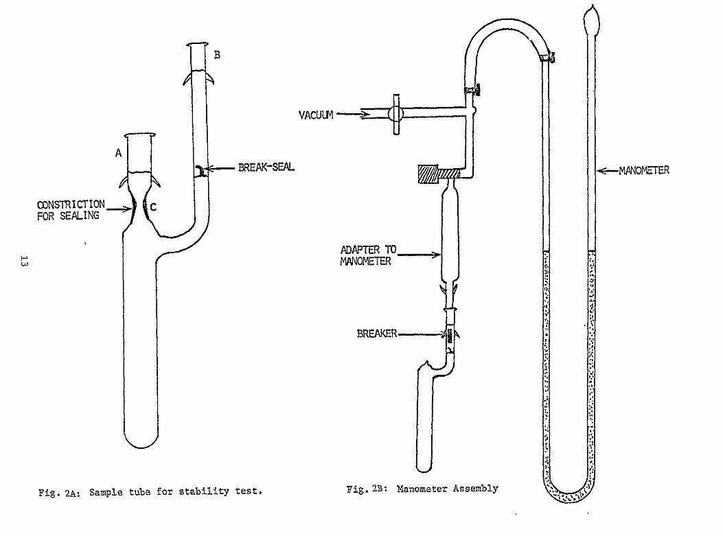