Embed Size (px)
Citation preview

Feasibility Study: Developing Integrated
Herder Delivery and Ignition Systems
Prepared for:
Oil Spill Recovery Institute P.O. Box 705
Cordova, AK 99574
Submitted by:
Tactical Electronics 2200 North Hemlock Ave Broken Arrow OK, 74012
Summary In-situ burning (ISB) of oil spills at sea is a proven response technique that works with and without the
presence of ice. In the past, ISB has relied on the use of fire-resistant oil booms that can collect the oil
and concentrate it enough to produce the necessary thickness to ignite and burn. Recent research and
testing over the past ten years has shown that approved (US EPA) chemical herding agents (derived
from commonly encountered compounds used for example in toiletries, hair products, cosmetics, and
skin care) applied in very small doses around the edges of a spill can thicken the oil without needing to
use a boom. This opens the possibility of developing a new response tool where the herding agent and
ignitors are both applied from a single manned helicopter (or several robotic helicopters).
The overall purpose of this project is to explore and evaluate alternate aerial and surface methods of
combined herder delivery and ignition systems and propose concepts that justify further development
and testing.
The aim is to create effective oil spill removal systems that can be quickly transported to an offshore site
and deal with a spill before it spreads over a large area. The most important benefit of this tool apart
from the speed of response, is its ability to operate independently without the need to have vessels at
the spill location.
Anticipated benefits include:
• Time: herder/burn systems can be delivered rapidly by helicopter or fixed wing aircraft to an
offshore site long before surface vessels can arrive on scene.
• Safety: herder/burn systems operated from a helicopter or unmanned surface vehicles
eliminate the risks to personnel of launching small boats into open seas or in ice.
• Flexibility: herder/burn systems expand the suite of available response options to deal with
spills in open water and ice-covered waters.
Field tests in Canada being proposed for the 2021-time frame could provide an invaluable opportunity
for a number of U.S. and Canadian Oil Spill Response Organizations (OSROs) to observe any new
herder/burn delivery systems developed through this project. Positive results from these test
programmes could encourage regulators to develop guidelines that encourage the use of herder/burn
strategies and encourage OSROs to stockpile these new systems at an operational readiness level.

2
Table of Contents
Summary ...........................................................................................................................................1
1. Introduction ...............................................................................................................................4
1.1 Background .........................................................................................................................4
1.2 Scope of Work .....................................................................................................................4
2. History and Development of Integrated Herder/Burn Systems .....................................................5
3. Delivery Systems ........................................................................................................................7
3.1 Delivery System Comparison ...............................................................................................7
3.1.1 Manned Helicopters Using Existing Herder System ................................................................................. 7
3.1.2 Drones Including Recent Advances in Payload and Endurance ............................................................... 8
3.1.3 Unmanned Surface Vehicles .................................................................................................................. 11
3.2 FAA Regulatory Requirements ........................................................................................... 12
4. Ignition Systems ....................................................................................................................... 13
4.1 Verision 2 Cartridge Activated Device (TECAD) ................................................................... 13
4.2 Alternative Ignition Sources ............................................................................................... 16
4.2.1 Visco Fuse .............................................................................................................................................. 16
4.2.2 Resistance Wire ..................................................................................................................................... 17
4.2.3 Steel Wool .............................................................................................................................................. 18
4.2.4 Incendiary Sphere .................................................................................................................................. 18
4.2.5 Ferro Rod ............................................................................................................................................... 19
4.2.6 Hybrid Canon Nichrome ........................................................................................................................ 20
4.2.7 String of Pearls (Dragons Tail) ................................................................................................................ 20
4.3 Operational off-the-shelf Surface and Airborne Ignition Systems ........................................ 21
4.3.1 Drone with ignitor sphere hopper ......................................................................................................... 21
4.3.2 Flamethrower Drones ............................................................................................................................ 22
4.3.3 ATV Drip Torch ....................................................................................................................................... 22
4.3.4 Terra Torch ............................................................................................................................................ 23
5. Integrated System Conceptual Designs ...................................................................................... 24
5.1 Concept 1 –USV ................................................................................................................. 24
5.2 Concept 2 -TECAD .............................................................................................................. 27
6. Conclusions and Recommendations for Phase 2 ........................................................................ 28
7. Links, Videos, Drawings and Photographs………………………………………………………………………………….29
Appendix – Ignition Test Data Sheets ...................................................................................................

3

4
1. Introduction
1.1 Background
In situ burning (ISB) of oil on the sea surface both in open water and in pack ice conditions is a well
proven technique documented in numerous field trials (e.g. Canadian, US and Norwegian Arctic,
Norwegian North Sea, and the East Coast of Canada) and large-scale responses to actual incidents (most
notably Macondo/Deepwater Horizon). Over the past decade, extensive research in laboratory, basin
experiments and at-sea trials has confirmed the effectiveness of herding agents to thicken oil slicks that
would otherwise be un-ignitable. Industry-sponsored research through the Arctic Response Technology
JIP (ART JIP) investigated the windows of opportunity to utilize herders and demonstrated the
operational viability of aerially applying herders and ignitors. This work highlighted the need to
integrate the herding and ignition systems into a single platform for increased effectiveness and
efficiency (Potter et al. 2016, SL Ross and Danish Centre for Energy, 2015).
The development of suitable surface-based or aerial platforms will facilitate the use of herding and
burning as a rapid aerial response tool that can initiate oil removal from the marine environment
without relying on having marine support at the spill site. This project considers systems mounted on
manned and robotic helicopters as well as remotely operated surface vehicles. A combination of these
systems deployed as circumstances permit, will greatly expand the applicability of ISB in dealing with
offshore spills before the oil has a chance to contaminate very large ocean areas.
1.2 Scope of Work
The scope of work defined at the outset of the program is summarized as:
1. Review the history and development of integrated herder delivery and ignition systems.
2. Broadly explore options for integrated systems that can utilize a single helicopter or other delivery
systems such as an unmanned aerial vehicle (UAV) or unmanned surface vehicle (USV). Examples
include but not limited to:
• Helicopter skid mounted winch platform with remote pilot controls and multi camera
observation platform.
• Small all-in-one “coffin” package with herder container, GPS geospatial mapping and
tracking, and ignition component launcher lowered by winch into water and towed
behind helicopter.
• Binary chemical incendiary “ping pong ball” launcher.
• Swarm of “Tennis ball” wide cast incendiary bomblets with RF radio electronic ignition
control
• Hand deployed, disposable “toy” remote controlled torpedo thrown from helicopter
and steered into oil with electronic incendiary ignition control.

5
• Agricultural UAV multirotor pesticide/herder dispersal platform with remote ignition
components launcher.
• USV to be deployed from responder boat deck with herder tank, remote guidance and
control and remote ignition components to replace helicopter deployment.
• Slow burn “Dynamite” type fuse deployed on a reel from helicopter to be spread across
wide area on top of herded oil with electronic remote ignition box attached.
3. Review and screen initial concepts by contractors with expertise in ISB as well as certification
processes and challenges governed by the FAA. The goal in this process is to eliminate designs
that have a low probability of success either on technical or regulatory grounds.
4. Create a final whitepaper (this report) detailing the most promising options, which could be used
as a basis for further development and testing. The paper will provide conceptual designs for three
to five of the most promising concepts, including:
• 3D CAD drawings.
• Experiment results including “tabletop” tests
• Video and/or photographs of any site testing, or full-scale demonstrations.
• Documents or papers provided by expert consultants.
• Recommendations and conclusions.
2. History and Development of Integrated Herder/Burn Systems This project is a logical extension to a series of tank, basin, and field trials carried out during two
industry-sponsored Joint Industry Projects (JIPs) over the past twelve years: SINTEF Oil in Ice JIP (2006-
2010) - https://www.sintef.no/projectweb/jip-oil-in-ice/ and IOGP Arctic Response Technology (ART) JIP
(2012-2017) - http://www.arcticresponsetechnology.org/. Those programs provided the necessary field
validation for lab and basin studies that show how effective herding agents can be in thickening oil slicks
on the sea surface (with and without the presence of ice). The combination of herding and burning
formed the basis for a new response strategy that can be initiated without depending on prior
deployment of vessels or maintenance of fire-proof booms. Improved safety was a major motivating
factor with the goal of eliminating the need for small boat crews to be out in the open ocean.
Large-scale basin testing carried out for the ART JIP by SL Ross Environmental Research and the
University of Alaska at Fairbanks in 2015 proved the viability of applying herders around the perimeter
of a slick from a helicopter cabin-mounted system (tank, pump and retractable hose reel) previously
developed in a program sponsored by ExxonMobil and described in (Potter et al. 2016). The same
project demonstrated the ability to ignite the slick with a helicopter slung Helitorch™ soon after herder
application. A subsequent small-scale test in Canada proved that small unmanned helicopters could
deliver herder and a single ignition source.

6
The drawback of having to apply the herder and then return to a staging point and pick-up a Helitorch™
became immediately apparent in the Alaska basin tests. The need to overcome this problem led to a
follow-on project under the umbrella of the same JIP to develop a helicopter-slung ignitor package to fly
at the same time as existing internal herder delivery system.
A prototype mechanical carousel that ejected ignitor cartridges was tested at the CRREL research
laboratory in Hanover, NH in 2016 and flown with mixed results from a helicopter in 2017. Results
showed that the system needed considerable work to stabilize its flight characteristics and overcome
the packaging limitation of accommodating a relatively small number of discrete ignitor cartridges.
http://arcticresponse.wpengine.com/wp-content/uploads/2017/09/Report-Integrated-Igniter-Herder-
Application-System.pdf
The ability to accurately lay down a line of multiple ignition sources was seen as a prerequisite for
successful ignition. In an operational setting multiple ignition points need to be set down across the
upwind edge of a thickened slick. Historically, the Helitorch™ served in this role but the limitations of
slinging the torch any distance and still having enough fuel to carry out an effective response forced a
re-examination of possible new ignition systems that could overcome these constraints.
As a result of the earlier tests and assessments of ignition devices, several criteria were developed as
necessary for any new herder/burn tool to become a practical operational system:
1. The helicopter must be able to transit to the offshore site at a speed close to its normal cruise
and not be unduly constrained by having to carry an underslung load like the Helitorch™
2. The capacity of the ignition system in terms of treatable slick area needs to match the herder
tank capacity. Ideally, the integrated system should be capable of treating multiple slicks
before having to replenish either the herder or ignition components
3. The system should include a downward looking camera that can video the oil on the water
surface during the herder spray and ignition operation. This “eye in the sky” view is considered
essential so that operators can effectively direct the herder spraying operation and ignitor
deployment – as demonstrated clearly during oil on water trials in Norway in 2016
4. The system should include instrumentation that allows quantification and cataloging of the
amount of herder delivered during each spray pass and the coordinates and track of the system
while herder is being sprayed and ignition devices are being deployed
The limited endurance of any helicopter-based system led to the early consideration of alternative
herder/burn delivery systems. Unmanned surface vehicles (USVs) emerged as a rapidly evolving
technology that could solve the problem of having sufficient time on site to herd and ignite multiple
slicks over a time period of tens of hours (or more) compared to a few hours at most for systems tied to
a helicopter.

7
3. Delivery Systems This chapter deals with the initial broad consideration of three delivery options using a combination of
aerial and surface deployment.
1. Manned helicopter carrying both the herder delivery and ignition systems
2. Unmanned surface vehicles delivered by helicopter and/or fixed wing aircraft or self-powered
transit from shore
3. Robotic helicopter operating off a support vessel close to the spill
In each case, the delivery options were explored in terms of:
• Certification and approval with requisite agencies – principally the FAA (See 3.2)
• Delivery speeds and achievable range to an offshore location
• Deployment – e.g. winch or direct drop (parachute aided)
• Weather limits and downtime – e.g. visibility, winds, waves
• Endurance on site
• Real time slick surveillance e.g. through elevated and integral cameras
• Payload
• Redundancy e.g. alternative communications links
• Potential for possible replenishment at sea
• Recovery (helicopter or support vessel)
The integration of herder application and ignition systems on the delivery vehicle is considered key to
developing an operational response tool (See two concepts presented in Chapter 5). USVs will require
the ability to establish and maintain reliable long-range communications links with on-site (overhead)
and off-site controllers.
3.1 Delivery System Comparison
This section compares the different delivery systems considered in this study according to certain
criteria judged essential to achieve success – see 3.0 above.
3.1.1 Manned Helicopters Using Existing Herder System
Current solutions require multiple flights for a helicopter to first pick up and deliver the herder
application equipment from a staging point to the spill site and then return to the staging point to drop
off the equipment and then pick up a Helitorch™ (or similar) equipment and deliver it back to the spill
site for application. The drawback of having to apply the herder and then return to a staging point and
pick-up a slung load to ignite the slick became immediately apparent in the Alaska basin tests.
Additional limitations include the significantly reduced range and speed when slinging, and the time lag
between herder application and ignition that could reduce herder/burn effectiveness.

8
Using two helicopters in the air at the same time could potentially solve the time lag problem but this
would greatly complicate the response operation while introducing additional safety concerns and cost.
3.1.2 Drones Including Recent Advances in Payload and Endurance
A limited number of projects employing smaller commercial vertical take-off and landing (VTOL) drones to support aerial ignition applications were discovered in our research. Replacing full-scale helicopters with less expensive unmanned equipment is an attractive option and removes the human safety element. However, to date, the limited range, endurance and payload capacity of commercially available drones have been major factors impeding their broad application to offshore oil spill response. The recent development of agricultural drones has overcome some of the performance limitations of previous VTOL projects. Although not common in United States, several other countries utilize agricultural drones more frequently. Larger companies such as Yamaha have been manufacturing commercial agricultural drones since 1991. Here are a few examples of commercially available agricultural drones. Thea 140 Hybrid
• 45 minutes flight time • 2.5-gallon removable application tank • 2’ X 2’ X 2’ folded • 5’ X 5’ X 2’ unfolded • 25 MPH max speed

9
Skyfront G2K hybrid
• 5-hour flight time • 8.8lbs payload capacity • 15 to 104-degree operation • 25 mph wind gust tolerance • 110-mile flight range • 36 MPH speed • Fuel injected • Collapsible
These agricultural applications feature technologies such as radar, LIDAR, hyperspectral cameras and autonomous operation. Prices start at under $10,000 and can exceed $200,000. Another advancement to come out of the agricultural drone research efforts is the development of Hybrid gas/electric motors. Present-day batteries are large and heavy and have very limited operational times. Gasoline engines are primarily limited to single rotorcraft platforms (RC helicopters). This is because a multi-rotor aircraft (quadcopter, octocopter, etc.) requires very fast manipulation of the individual rotor speeds to maintain controllable flight characteristics. A gasoline engine usually operates at a fixed rotor speed on a helicopter and the pitch of the rotor blades is manipulated to change aircraft attitude. The newer solution is a gas/electric hybrid. It consists of a gasoline engine driving an electric generator to produce electrical power for the electric rotors. This has extended the operational times to several hours in some cases. Video footage of a drone that can operate for more than 7 hours is available here: https://www.youtube.com/watch?v=a7bxb0Fb060

10
Here are some general specifications and examples of Hybrid engines. Hybrid Gas/Electric Motor
• Generator output: 2.4kw continuous
• Generator weight: 9.2lbs
• Recommended Max take-off Weight: 50lbs
• Fuel consumption: .6 gallon/h at 2400W output
• Operational temperature: -20 ~ 40°C
• Dimension: 14x13x10 inches

11
3.1.3 Unmanned Surface Vehicles
Tactical Electronics attended a meeting in San Ramon, California to review project progress and direction. Various USV platforms with different evaluation criteria requirements were discussed and explored in terms of:
• Cost
• Weight
• Transportability
• Capability
• Various operating environments One solution that appeared to meet all of the criteria was a modified consumer personal watercraft. These platforms have become vastly popular and inexpensive. Available models start at one-man sport watercraft and range all the way to large three and four person vessels.
The demand for these products has driven the advancement of technologies in fuel efficiency, engine reliability and rugged, light weight material development. For example, hull material like Polytec ™ has several advantages over conventional fiberglass. Other advantages are:
• Relatively lightweight and can be carried by a helicopter or small fixed wing aircraft. • Payload 400 LBS (50 gallons of fuel/herder). • Speed 40-65 MPH. • Very fuel efficient. • Longer operational time-on-target than helicopter solutions.
Smaller and more nimble watercraft are being developed for emerging sport applications. Motorized surfboards and wake boards could form the basis for smaller and more portable USV platform in an oil spill response environment. Example specifications include:
• 35 -40 MPH. • 40 lbs. dry weight. • 180lbs payload (20 gallons of fuel/herder). • 4 hours operation (additional tank and 50% full throttle). • 7’ 6” long by 2’ 5” wide.

12
3.2 FAA Regulatory Requirements
One of the challenges of this project was the need to transport a herder/burn delivery solution via
helicopter or fixed wing aircraft. Prior efforts have identified potential difficulties in gaining regulatory
approval to carry gelled fuel or cartridge style ignitors internally within an aircraft cabin. The existing
Helitorch™ was approved for use decades ago on the basis that it can be punched free of the helicopter
at any time with a pilot activated switch in the cockpit that opens the belly hook.
Continuing with this proven ignition device was not viewed as an attractive option because of the
drawbacks outlined previously – mainly limited speed and range.
Some of our initial research and consultation led to an Oklahoma company (Commuter Air Technology /
Meta Special Aerospace LLC) that specializes in aircraft modifications to accept external equipment and
sensor platforms. They are familiar with certifications and processes necessary for FAA approval.
Additional research identified a company that currently provides sling load services and aircraft
contracting around the globe - United States Aviation (USA) based in Tulsa, Oklahoma. USA provides
helicopter sling load services under the authority of an FAA Rotorcraft External Load Operating
Certificate, Federal Aviation Regulations Part 133 (certificate #1USL530O). The company utilizes an S-70
Blackhawk helicopter with a lift capacity of 8,000 pounds and advertises lift capabilities which include:
Aircraft and boat recovery, disaster relief, fuel and water tank transport, oil rig support and transport,
pipeline placement, and aircrane sling loading. According to their Chief Pilot, Tim Reather, USA operates
as a “Will Carry” HAZMAT operator. Because of the varied nature of transporting HAZMAT in external
load operations, each operation requires a “Pipeline and Hazardous Materials Safety Administration
(PHMSA) Special Permit and Mitigation Plan”. This is considered routine and the company does not
foresee any difficulty in obtaining the necessary permits once the particulars of the igniter components
are known.
See FAR Part 133 Will Carry Certificate #1USL530O (attached at the end of this report)
Tactical Electronics has some testing planned for mid-November 2019 and will utilize the services of USA
to drop a fueled USV into a local lake. This will provide first-hand exposure to the entire process of
contracting, certifying and getting FAA approval for operations similar to that required to implement the
conceptual solutions presented in Section 5.0.
13
4. Ignition Systems The process of assessing different ignition systems involved three avenues of research and
development:
1. Review the original cartridge ignitor developed by DESMI through the ART JIP and develop an
improved and completely redesigned cartridge activated device (TECAD) for test drops into a
lake from a helicopter. This second-generation ignitor would incorporate a number of
improvements drawing from experiences in tank testing the original ignitors at CRREL and
described in the JIP test report referenced earlier – See 4.1
2. Test at small to meso-scale a wide range of different ignition sources as alternatives to the
traditional Helitorch and/or cartridges – See 4.2
3. Review examples of operational Drone and Surface Vehicle Ignition Systems – See 4.3
4.1 Version 2 Cartridge Activated Device (TECAD)
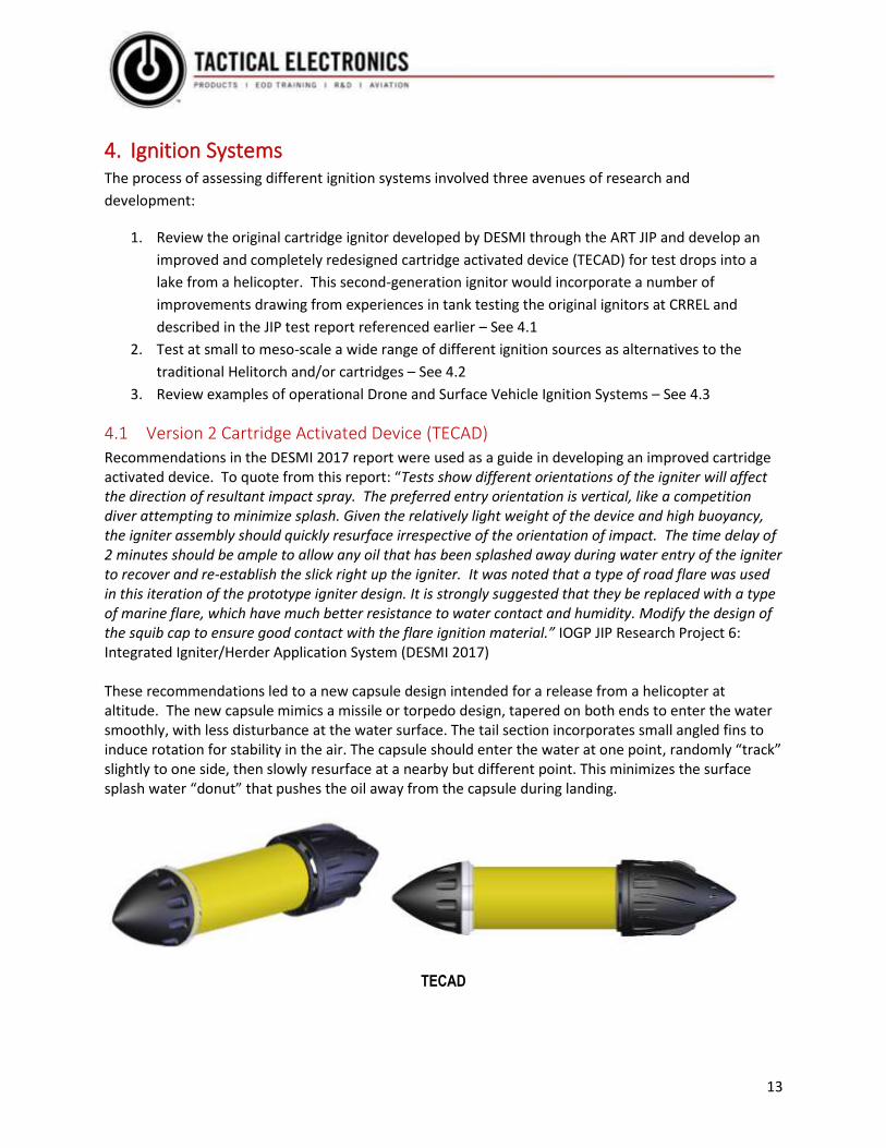
Recommendations in the DESMI 2017 report were used as a guide in developing an improved cartridge activated device. To quote from this report: “Tests show different orientations of the igniter will affect the direction of resultant impact spray. The preferred entry orientation is vertical, like a competition diver attempting to minimize splash. Given the relatively light weight of the device and high buoyancy, the igniter assembly should quickly resurface irrespective of the orientation of impact. The time delay of 2 minutes should be ample to allow any oil that has been splashed away during water entry of the igniter to recover and re-establish the slick right up the igniter. It was noted that a type of road flare was used in this iteration of the prototype igniter design. It is strongly suggested that they be replaced with a type of marine flare, which have much better resistance to water contact and humidity. Modify the design of the squib cap to ensure good contact with the flare ignition material.” IOGP JIP Research Project 6: Integrated Igniter/Herder Application System (DESMI 2017) These recommendations led to a new capsule design intended for a release from a helicopter at altitude. The new capsule mimics a missile or torpedo design, tapered on both ends to enter the water smoothly, with less disturbance at the water surface. The tail section incorporates small angled fins to induce rotation for stability in the air. The capsule should enter the water at one point, randomly “track” slightly to one side, then slowly resurface at a nearby but different point. This minimizes the surface splash water “donut” that pushes the oil away from the capsule during landing.
TECAD

14
In the stable floating mode following entry, most of the capsule is submersed under the water surface with just the top nose cone visible above the water line. This reduction in surface area above the water line reduces the chance that the capsule will be blown off course by wind and waves. A marine flare is incorporated to replace the road flare used in previous experiments. This reduces the affect of moisture and humidity on the device and greatly improves reliability. The squib cap is deeper and fixed to the inner sleeve, eliminating movement of the flare or its components. There are also 2 squib igniters per flare for redundancy. This was one of the causes for failure in previous experiments. The gelled fuel sack is positioned above the flare with weep holes along the circumference allowing the ignited fuel to spill out in all directions. This design will hold 300ml of fuel, the same as previous CAD capsule; however, a larger fuel sack can be accommodated with different size screw caps. The illustration below shows the overall design and exploded view of the new capsule and ignition cartridge.

15
The ON/OFF switch is protected within the removable bottom screw cap. This eliminates inadvertent or accidental activation. The shelf life of the device depends on the battery (avg 7-10 years). Once activated, the standby operational time would be several weeks. The bottom section of the device is clear plastic and reveals an encapsulated LED indicates function (on/standby/armed/etc.…). An off-the-shelf processor and radio module is incorporated for logic and control. This capability could expand the use of the new capsule in other areas such as permitting remote RF activation. These radios have MESH capabilities to ensure the activation signal is propagated thorough out all the deployed devices. The processor/radio design also implements a “handshake” protocol during activation signaling and confirmation. This protocol requires an agreement between the air-based activation transmitter and the in-water capsule receiver before the squib is ignited – much safer than a simple timer circuit. This was one of the failure points in the 2016 tests at CRREL where an accidental activation while the capsule was still in the launching mechanism started a fire and ignited other adjacent capsules. Accelerometers can be used to confirm deployment and water landing. Other suggestions for future
design iterations and applications could include ignition confirmation transmission, underwater sonic
emission to haze marine animals, and centrifugal ARMING sequence for safety.
In practice, an integrated system employing the new ignition cartridges would utilize the existing herder hose reel assembly used from a helicopter in the 2015 basin tests http://arcticresponse.wpengine.com/wp-content/uploads/2017/09/poker-flats-report-final.pdf

16
4.2 Alternative Ignition Sources
A series of small-scale tabletop tests assessed several alternative ignition sources. In addition, a number of successful tests were repeated in a larger test tank. The test data sheets in Appendix A describe the general set-up and test protocols. Results are summarized below for each potential ignition source. Additional test videos and photographs are in the attached file folder “Tabletop Test Pictures”.
4.2.1 Visco Fuse
This project tested three different types of “off-the-shelf” Visco fuse.
• Canadian Igniter Cord
• American Visco Fuse
• Basic Cannon Fuse
Cannon fuse is a fuse that is thicker, steadier burning, and often extra coated to be more waterproof. Most cannon fuses of high quality can burn while under water. Cannon fuse is normally red or green in color.
Flying fish fuse is a modified type of fuse used in fireworks. The composition in the core is a metallic spark composition or another effect instead of/as well as black powder. Flying fish can thus perform as a main effect instead of just an initiator. For example, simply lighting a short piece of flying fish on the ground makes it fly through the air, seeming to swim in random directions while emitting sparks and noise
Igniter Cord is a commercial grade of fuse that is designed to ignite multiple safety fuses. Igniter cord burns with an external, visible flame, is often heavily lacquered for water resistance, and sometimes has an inner wire core for mechanical strength
Of the three fuses tried, only the Canadian Igniter Cord could ignite the oil. This was attributed to the presence of a metal wire running inside of this type of fuse. This wire seems to allow the fuse to burn hotter, glowing slightly red as the fuse burns down it. During the test, the fuses were held suspended over the oil sample in the test beaker, with the end passing through the oil sample on top of the water down to the bottom of the beaker. The Canadian Ignition Cord wire held the fuse in place during the entire fuse burn length. This allowed the fuse to burn above and into the oil sample. The other fuses tested lacked this “support” wire to holding the fuse in place during the burn. As the fuses burned down past the alligator clips holding it, the fuse would release from the alligator clip and fall down past the oil sample to the bottom of the beaker. There were inconsistencies in underwater burning. About 50% of the time the fuse would extinguish in the oil. All of the fuses that burned underwater failed to ignite the oil. Some fuses would soak up the oil resulting in an extinguished fuse. Some of these inconsistencies are considered due to handling of the fuse and manufacturing variances.

17
Recommendations: Visco Fuse in the form of the Canadian Igniter Cord is a reliable product for its intended purpose but is not an effective oil ignition device. The concentration of heating on the small concentrated surface area of the fuse limits effectiveness. Further testing and development is not recommended.
4.2.2 Resistance Wire
Two different wire samples were tested:
• 18 Gauge Iron-chromium-aluminum (FeCrAl) Kanthal™ is usually used for high temperature furnaces in the heat treating, ceramics, glass, steel, and electronic industries. Other common applications include: heating elements (hair dryers, ovens, toasters, kilns), model and high power rocket motor and recovery ejection charge ignition, heat sealers, poly cutters, foam cutters, resistors, rheostats, current-temperature controls, pyrotechnic ignition, e-cigarettes, lab inoculating loops, release mechanisms, and ceramic support in kilns.
• 24 Gauge Nichrome (NiCr, nickel-chrome) wire is made of a non-magnetic alloy composed primarily of nickel, chromium, and iron. Nichrome is characterized by its high resistivity and good oxidation resistance. Nichrome wire also has good ductility after use and excellent weldability. The number that comes after the Nichrome wire type indicates the percentage of nickel in the alloy. For example, "Nichrome 60" has approximately 60% Nickel in its composition. Applications for Nichrome wire include heating elements of hair dryers, heat sealers, and ceramic support in kilns.
Both wire samples were able to ignite the oil. The larger Kanthal™ Wire took more current to ignite the oil sample and in spite of being more robust than the thinner Nichrome, showed no clear advantage over Kanthal™. Various lengths were tested, and all were successful. One foot was the longest sample tested due to power supply limitations. Successful ignition occurred 100% of the time. Both samples maintained a sustained red glow for extended periods of time. No test exceeded 5 minutes. The success of the resistance wire was unexpected. It is anticipated that by controlling voltage and current variables the red glow could be maintained indefinitely. This view is also supported by the long-term durability of resistive wire in daily use today (toasters, hairdryers, etc.,) One variable to consider would be any adverse effect of the oil on the wire surface over time. This is an encouraging solution because it can be re-used repeatedly. Some of the USV or “Toy” Remote Control Boat solutions could easily incorporate this ignition source. Recommendation: Recommendations are for further test and development of this solution.
Implementation with other suggested delivery vehicles could be explored. The advantage here is the
extended time of high temperature delivery at a concentrated point within the oil sample. In addition,
this solution would not be subject to any FAA regulations or constraints during transport.

18
4.2.3 Steel Wool
Steel Wool, also known as iron wool, wire wool, steel wire or wire sponge, is a bundle of very fine and flexible sharp-edged steel filaments. Steel wool is made from low-carbon steel in a process similar to broaching, where a heavy steel wire is pulled through a toothed die that removes thin, sharp, wire shavings.
The samples were tested in various configurations. Product packaging made it difficult to test consistent samples. The steel wool source began as large pad. Approximately 6” strands were pulled away from the pads and lightly rolled into a “mustache” configuration as thick and thin samples. The Steel Wool was then connected to the lab power supply and voltage slowly increased to achieve ignition. All the samples ignited the oil. The wool pad acted as a sponge and wicked up the oil, apparently making it more flammable. All testing was with the sample within and above the oil, not submersed. Ignition times varied depending on the thickness of the sample wool. The only failures were samples thinner than about 1/2-inch-thick. which would burn out in the middle before initiating oil ignition. Recommendation: This is a limited solution with some possibilities. Although successful ignition was achieved, the steel wool is a one-time use solution, unlike the resistive wire applications. Further development of this concept is not recommended.
4.2.4 Incendiary Sphere
Premo Fireballs are 32 mm (1.25 in.) in diameter, consisting of approximately 3.0 grams of potassium
permanganate. https://www.sei-ind.com/products/premo-fireballs/
The rate of chemical reaction is dependent upon the particle size of the potassium permanganate and the concentration of the ethylene glycol. Combustion occurs within approximately 20 seconds of the sphere’s injection with approximately 1 ml of common automotive coolant (ethylene glycol) Dragon Eggs are smaller with the same ignition properties. A smaller sphere could mean more spheres in the transport container to ignite more slicks. With the smaller diameter, there is also a reduction in the Magnus effect (side force exerted on a spinning ball or sphere) which would improve accuracy. This is a proven product that is readily available and used in forestry today. The system is well documented and tested. A Styrofoam shell and modified launch barrel were considered as a means of overcoming concerns about the performance of the spheres on water. Subsequent conversations with the manufacturer indicated that the spheres are buoyant in their current configuration and commonly used in the Florida everglades to burn off vegetation in the swamplands. As a result, the spheres remained in an unmodified form for these tests.
19
The tests utilized two different sphere products: Premo spheres and Dragon balls. An outside consultant with experience using these systems in the everglades indicated that in actual operations only about 20% of the spheres ignite, depending on the sphere’s orientation after landing on the water. This low success rate in the field, points to the need for some form of modified Styrofoam shell to increase the effectiveness of this solution on the water and prevent sinking. Our initial testing proved inconsistent results.
Initial tests used a pre-diluted 50/50 anti-freeze injection that failed to initiate the chemical reaction. More acceptable results were recorded after adjusting the mixture. The tabletop tests were all successful in oil ignition for the spheres that achieved internal ignition. The spheres were tested in a fixed position so and did not replicate a field situation where experience showed a high percentage failure rate. Recommendation: A modified form of these spheres may represent a possible solution. Actual field testing is recommended, possibly coinciding with a future event at OHMSETT.
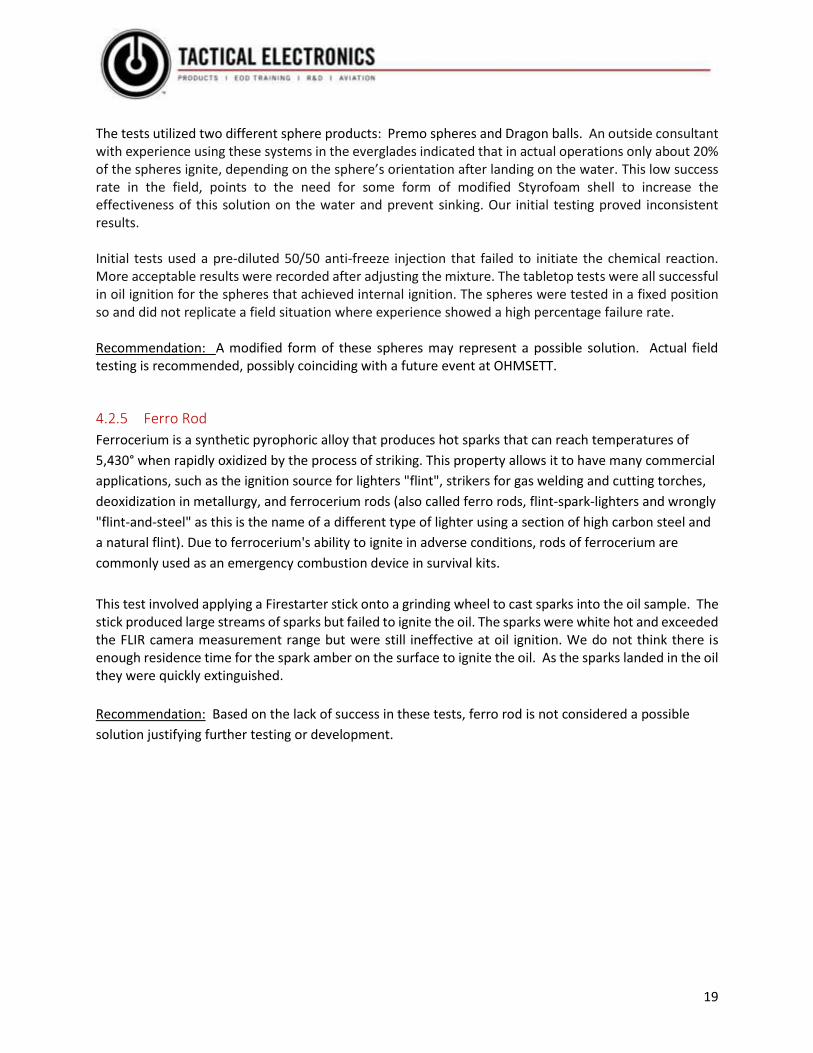
4.2.5 Ferro Rod
Ferrocerium is a synthetic pyrophoric alloy that produces hot sparks that can reach temperatures of
5,430° when rapidly oxidized by the process of striking. This property allows it to have many commercial
applications, such as the ignition source for lighters "flint", strikers for gas welding and cutting torches,
deoxidization in metallurgy, and ferrocerium rods (also called ferro rods, flint-spark-lighters and wrongly
"flint-and-steel" as this is the name of a different type of lighter using a section of high carbon steel and
a natural flint). Due to ferrocerium's ability to ignite in adverse conditions, rods of ferrocerium are
commonly used as an emergency combustion device in survival kits.
This test involved applying a Firestarter stick onto a grinding wheel to cast sparks into the oil sample. The stick produced large streams of sparks but failed to ignite the oil. The sparks were white hot and exceeded the FLIR camera measurement range but were still ineffective at oil ignition. We do not think there is enough residence time for the spark amber on the surface to ignite the oil. As the sparks landed in the oil they were quickly extinguished.
Recommendation: Based on the lack of success in these tests, ferro rod is not considered a possible
solution justifying further testing or development.
20
4.2.6 Hybrid Cannon Nichrome
This test sought to create a hybrid that used the resistive wire wrapped around a thicker Visco fuse. The concept was that the resistive wire would ignite the fuse all at once, linearly, instead of just from the end. These tests were successful, causing a more dynamic flame than achieved with either the resistive wire or Visco fuse. The hybrid solution could be used for the one-time use “toy” remote control boat scenario or incorporated into a version of the Dragons Tail (4.2.7). Recommendation: These tests were successful, but the concept is still limited by one-time use. The
resistive wire is probably a stand-alone solution and without additional enhancements. There is no
justification for further testing or development of the hybrid system
4.2.7 String of Pearls (Dragons Tail)
Dragons Tail is a proposed small control box with the TECAD ignition electronics, and a long “tail” of resistive wire passed through several ping pong balls spaced out every 1 foot or so containing alternative ignition sources like steel wool with monochrome wire stitching on the outside. One control box could be tethered to several Dragon Tails. The ping pong balls are highly flammable and provide positive buoyancy on top of the oil sample. The Dragons tail could be released from a helicopter providing a “web” across more surface area of the oil sample or towed behind a USV or remotely controlled boat. Testing showed limited success. Oil samples were ignited every time in the tank and the tabletop lab. However, keeping the ping pong balls floating on the sample was the challenge. Some ping pong balls would stay afloat, and some would sink because of the nichrome hole passing through the ball. The balls that stayed on the oil sample surface did ignite the oil sample. We tested single ping pong balls in the tabletop exercise, multiple ping pong balls in the outside tank and a single ping pong ball in the outside tank. Improvements of the ping pong balls buoyancy could use filler material such as expandable foam. Styrofoam sleeves were discussed early on in the project (see 4.2.4), but tank testing revealed that Styrofoam breaks down in petroleum products very quickly. Recommendation: These tests were partially successful, but the limitation of one-time use remains. In some cases, such as dropping a disposable remote-controlled boat, or direct helicopter drop, this limitation could be acceptable. Additional testing could determine whether a modified system based on this concept has sufficient merit for further development.

21
4.3 Operational off-the-shelf Surface and Airborne Ignition Systems
There are a number of operational ignition systems already mounted on drones, ATVs, and other
vehicles. The intent here is demonstrate the availability of proven hardware that could be adopted to a
number of the aerial and surface delivery systems being considered in this study. Examples are
described below and links to various commercial solutions are included at the end of this report.
4.3.1 Drone with ignitor sphere hopper
Ignuis by Drones Amplified is an incendiary sphere dropper that consists of a hopper that holds approximately 100 spheres, and ethylene glycol for ignition. The sphere is injected during the drop, initiating the chemical reaction producing the flame within approximately 20 seconds. This hopper can be fitted on different drone platforms. A popular airframe is the DJI M600. The cost of this air frame with the hopper device is around $25k. This is a relatively new company producing products that are suited for forest fire management. This solution has various limitations for oil spill ignition applications. Flight time (as purchased) is 15-20 minutes. A trained operator would be necessary to fly this platform; landing on a moving platform such as a boat is challenging but doable. The small hopper volume would also limit effectiveness. Presumably the same buoyancy problems encountered during testing spheres in this project and high failure rates encountered in operational experiences, using igniter spheres with actual oil spills would apply to drone system as well.

22
4.3.2 Flamethrower Drones
The Throwflame WASP TF-19 is a flame thrower attachment device that can be used with several lager drone platforms. Useable fuel sources are straight gasoline, diesel-gasoline mixture or gelled gasoline. The company does sell a gasoline gelling compound. This system is capable of producing a flame 25 feet long. This system is currently used for power line cleaning, forestry and other remote fire applications. Cost with a DJI M600 and WASP are under $10k. The limitations and challenges are the same as listed above for the incendiary sphere hopper device. Flight time is about the same and the WASP can only produce a flame for about 100 seconds, not sufficient to ignite a slick. Video and links to a full specification sheet are provided at the end of the report.
4.3.3 ATV Drip Torch
Designed for ATV use, the 10-gallon drip torch has a 12-volt fuel pump. The torch can project a 2’ to 8’
flame. The torch arm locks into place in five different positions and releases if it strikes an object. Safety
features include two cut-off valves, mounted fire extinguisher, brush guards, and internal baffles.
Available in heavy-duty steel or lightweight aircraft-grade aluminum. Unit may be mounted on any
stable, off-road vehicle or tractor equipped with a 12-volt electrical system. This is a good example of a
smaller alternative to the Helitorch™ but he 10-gallon tank is too limiting for an offshore application.

23
4.3.4 Terra Torch
GelFire Systems GFS 45 Terra Torch is a compact 55-gallon ground-based fuel ignition system. The flexibility of being able to fit onto a wide range of platforms (UTVs, pickups, pumper units, trailers, tractor 3-point mounts, skid steers, jet/air boats, and dozers) allows an operator many options to operate effectively & safely in different conditions & terrain. The improved GFS Gel Gun allows operator to propel ignited gelled fuel safely & effectively of distances 25 to 75 ft into or onto specific target area creating an, accurate & safe method of fuel ignition. This would compare closely to the Helitorch™ system but intended for ground operations.

24
5. Integrated System Conceptual Designs This section presents conceptual designs for two of the most promising concepts. These concepts are
based on various project meetings throughout the contract with input and discussions from industry
consultants and experts in the field.
5.1 Concept 1. USV Solution
The Helitorch™ is well suited for forest fire applications. The transport distance is short, and precise
accuracy is not a major factor. These are close range operations in dry forest environments and
anywhere that the gelled gasoline lands catches fire.
As outlined earlier in this document Background 1.1, in situ burning of oil spills at sea introduces new
operational requirements including the possible need to transport the Helitorch™ as a slung load a long
distance offshore to reach a remote spill site. Once on location there is a need to distribute ignition
sources in fairly precisely defined target areas to efficiently ignite the slick. The Helitorch™ excels at
dropping a line of closely spaced ignition sources as proven in variety of large-scale testing including
trials at sea. However, the existing system imposes serious constraints on the distance that can be
covered to reach a slick from a shore base (in the absence of nearby support vessels or platforms to act
as staging bases). The presence of an unwieldy slung load like the Helitorch™ has a major effect on the
cruising speed of the helicopter and by association the range and endurance. The main idea behind the
use of herders and burning as an integrated strategy is to take advantage of the ability to rapidly treat a
remote slick offshore without the need to wait for slow surface vessels to arrive. The Helitorch™ in its
current form is not a viable solution to achieve this goal.
Igniting gelled gasoline is the currently proven ignition method employed in the Helitorch™ as well as
with igniters deployed by hand on the surface such as in the Deepwater Horizon response. The main
difficulty in developing gelled gasoline ignition systems that can be carried at higher speed internally in
the cabin is the challenge of getting certification approval from aviation authorities such as the FAA.
One of the original suggestions from Exxon/Mobil was a “casket” type all-in-one helicopter solution that
can carry both herder and gelled gasoline together to the spill site. The casket would be tucked up under
the helicopter during transport to reduce drag and then lower itself or a hose for herder and gelled
gasoline application and dispersal. Previous tests revealed challenges with this approach related largely
to the inherent mismatch between the herder and ignition capacities. It is relatively easy to carry
enough herder to treat multiple slicks but much more difficult to package and distribute a large enough
number of discrete igniter cartridges to burn all the oil that is herded. Again, the problem of limited
endurance on site once the helicopter has transited offshore greatly restricts the area and volume of
slicks that can be treated in a single mission.

25
This study looked at ways to combine the basic elements of herder application and ignition into a
different platform that overcomes the inherent limitations of a helicopter-based system. The resulting
concept utilizes an Unmanned Surface Vehicle (USV) that can be transported offshore by a helicopter or
fixed-wing aircraft and then deployed at the spill site operate autonomously/remotely while applying
herder and igniters over longer periods of time.
The USV platform presents and “all in one” integrated platform with several important benefits. At only
2+ ft in height, the USV will tuck right up against the underbelly of the helicopter, reducing drag to
maintain the original range and endurance.
Here are some important points to consider with respect to the USV herder/burn platform:
• Readily available parts and service in the field
• 400-500 LBS dry weight
• Payload 40-50 gallons of fuel/herder
• Speed up to 65 MPH
• Proven fuel efficiency (example 2 gallons per hour at full throttle)
• Projected operational time greater than 16 hours
• Can be deployed from a helicopter
• Potential to launch much further from the spill site than any unmanned air vehicle solution
• More rugged and less weather prone than UAV platforms
• Longer operational times Consideration has been given to using Unmanned Air Vehicles (UAVs) for herding and burning. In
comparison to UAVs, the USV platform is much more rugged and less prone to weather while providing
dramatically more capacity and endurance to remain on site while treating multiple slicks in a general
area.
The herder/burn USV can be operated remotely by multiple operators/responders in different locations:
onboard the deployment helicopter, onboard a loitering fixed wing aircraft, or a shoreside command
post anywhere in the world over an Iridium modem satellite or aircraft repeater link. Each
“operator/responder” would have full access to telemetry, video, sensor data and USV command and
control systems.
The probability of success for the USV concept using existing technology components is rated as high.
The main objective of developing a remote surface platform is to extend the operational times on site
while being more efficient and effective in treating target spills with precision. The vision for this
concept is based on previous and current research and supported by operational experience. Many of
the necessary components are already implemented and proven in other projects.

26
Herder/Ignitor USV Concept
27
5.2 Concept 2. TECAD Solution in Conjunction with the Existing Herder Delivery System The second concept solution uses the Version 2 Cartridge Activated Device (TECAD) described in detail
earlier in Section 4.1. As an integrated concept, the newly developed TECAD igniter cartridges would
replace the slung Helitorch™ used earlier, thereby providing an integrated system that would enable a
helicopter to achieve greater range and endurance with all systems mounted internally. As an
integrated system, the new cartridges would be mounted in the cabin along with the herder delivery
system developed by DESMI (for ExxonMobil) and tested in Alaska in 2015 – see links to relevant reports
in section 7. In those tests, the ignition was accomplished by picking up a Helitorch from the staging
point after applying the herder.
Version 2 Cartridge Activated Device Concept

28
6. Conclusions and Recommendations for Phase 2 Although these tests have proven limited success with alternative ignition sources, our opinion is that the current gelled gasoline method for ignition is superior amongst the other contenders. It is the helicopter delivery and application method that has its challenges, as documented throughout this and other previous reports. We recommend the design, development and prototype production of an autonomous USV system that can be deployed from a sea vessel or helicopter, with considerations of possible fixed wing deployment at later stages. This approach has several advantages over current application methods as outlined in section 5.1. Most of the capabilities suggested in the proposed concept are modifications or adaptations of off-the-shelf components. This effort would be more of an integration of existing technologies and less of a creation of new ones. We can also recommend the possibility of contracting with a single service provider for global aircraft
acquisition. Previous testing in Alaska utilized various helicopter equipment providers and processes
revealing some critical challenges causing operational delays, a single contractor could be a listed source
for “Work for Hire” contracting as needed for sling-load operations worldwide during an oil spill
recovery effort. Having a single point of contact familiar with the project, operations and processes
could streamline the effort and simplify aircraft acquisition from different unknown sources.
This recommendation only comes to mind because of our discovery during research that these types of companies exist. The Tulsa based USA company mentioned earlier in this report would be an example. Our last recommendation is the design, development and prototype production of a Version 2 Cartridge Activated Device (outlined in section 5.2). We feel this would be a relatively easy effort based on the testing and documentation of shortcomings revealed in the DESMI report. A Version 2 CAD could be a quickly developed tool used to bridge the gap between current Helitorch ™ applications and a further out developed USV solution.

29
7.0 Links, Videos, Drawings, Photographs
Basin Testing of Herding and Burning from a helicopter in 2015. This report describes the herder
delivery system installed internally in the cabin.
http://arcticresponse.wpengine.com/wp-content/uploads/2017/09/poker-flats-report-final.pdf
Tank testing and airborne trials with a prototype igniter cartridge carousel system slung from a
helicopter in 2016.
http://arcticresponse.wpengine.com/wp-content/uploads/2017/09/Report-Integrated-Igniter-Herder-
Application-System.pdf
Flame throwing Drone
Throwflame Drone: https://throwflame.com/tf-19-wasp/
Incendiary Sphere dropping drone
Drone Amplified Ignus: https://droneamplified.com/
ATV mounted flame throwers
Gelfire Tera Torch: http://www.gelfiresystems.com/gfs-model-45-terra-torch/
ATV Drip Torch: https://www.forestry-suppliers.com/product_pages/products.php?mi=15871
Incendiary Spheres
Premo Fireballs: https://www.sei-ind.com/products/premo-fireballs/
Tethered Drone examples
Powerline: https://www.ntpdrone.com/
Tethered Drone Systems: https://tethereddronesystems.co.uk/
Small Motorized surfboards
Jetsurf: https://shop.jetsurf.com/
Awake: https://awakeboards.com/

Appendix A – Ignition Test Data Sheets
Tabletop Test Setup and Equipment
The tabletop test was set up using 1000 ml glass beakers mixed with tap water and 35 grams of salt to produce a salinity value of 3.5%. This was as an average of ocean references. The test beakers were placed inside a secondary overflow containment pan to capture a spill or accidental splash of the oil sample while burning. Samples tested were exposed to open air between 1 and 8 hours. A large fire blanket was available during each test. 3-5mm of hoops oil was added to each sample surface. A FLIR E5 handheld camera was used to take pictures of the test in progress. A Sony HDR-CX240 Handycam was used to record during test. Ignited samples were extinguished with a steel plate lid placed on top. Our power supply was a TekPower TP1540E DC Adjustable Switching Power Supply 15V 40Amp.
Test Data Sheet Ignition material: • Nichrome 90 resistance wire • 24 AWG • 0.5105 mm • 1.5945 Ohms/ft Resistance Material description: Nichrome wire Test description: This test is to determine possible ignition of oil sample via nichrome wire. The nichrome wire will be placed into the oil with approximately 4” of exposed wire above the oil surface and 4” submersed below the surface. The wire will be connected to the lab power supply and voltage will slowly be applied. Voltage and current progress will be logged and recorded. Wire and surface oil temperatures will be logged and recorded with the FLIR thermal camera. Short wire lengths of 12” will be used in the tabletop testing.
Results: Successful ignition
The oil sample was around 80 degrees. The power supply was set to 0 volts and slowly increased. There was no visible activity from 0-3 volts however the FLIR thermal camera indicated a consistent temperature rise in the monochrome wire with voltage increase. There was also a consistent current rise with voltage increase. Between 3-5 volts the temperature of the wire exceeded the FLIR threshold. Also, smoke and boiling bubbles around the wire were visible. Once the voltage reached 12 volts at 10 amps, the oil sample ignited covering the entire surface of the beaker opening in flames. The FLIR camera indicated an oil surface temperature close to the wire at around 500 degrees. The measurements were recorded, and the flame was extinguished.
The test video and pictures can be found in the file folder “Tabletop test pictures” attached to this report under “Small Nichrome 90”. The FLIR images are sequential in number and toggle between visible image and thermal image. We are just showing the oil surface temperature, not the ignition source. The ignition source temperature is outside of our FLIR camera threshold.

Test Data Sheet Ignition material: • Material: FeCrAl Large Kanthal Wire • Brand: DMiotech • Average Wire Diameter: 1mm • Wire Gauge: 18 AWG • Melting Temperature: 1500C (2730F); Max. Operating Temperature:
1400C (2550F) Material description: Large Kanthal wire Test description: This test is to determine possible ignition of oil sample via Kanthal wire. The Kanthal wire will be placed into the oil with approximately 4” of exposed wire above the oil surface and 4” below the surface. The wire will be connected to the lab power supply and voltage will slowly be applied. Voltage and current progress will be logged and recorded. Surface oil temperatures will be logged and recorded with the FLIR thermal camera. Short wire lengths of 12” will be used in the tabletop testing.
Results: Successful ignition
The oil sample was around 90 degrees. The power supply was set to 0 volts and slowly increased. There was no visible activity from 0-3 volts however the FLIR thermal camera indicated a consistent temperature rise in the monochrome wire with voltage increase. There was also a consistent current rise with voltage increase. Between 3-5 volts the temperature of the wire exceeded the FLIR threshold. Also, smoke and boiling bubbles around the wire were visible. Once the voltage reached 12 volts at 18 amps, the oil sample ignited covering the entire surface of the beaker opening in flames. The measurements were recorded, and the flame was extinguished.
The test video and pictures can be found in the file folder “Tabletop test pictures” attached to this report under “Large Kanthal Wire”. The FLIR images are sequential in number and toggle between visible image and thermal image. We are just showing the oil surface temperature, not the ignition source. The ignition source temperature is outside of our FLIR camera threshold.

Test Data Sheet Ignition material: • American Visco Fuse • 3.5 MM • Amazon Supplier • 1-foot sample
Material description: American Visco Fuse Test description: This test is to determine possible ignition of oil sample via American Visco fuse. The American Visco fuse will be placed into the oil with approximately 6” of exposed fuse above the oil surface and 6” below the surface. The fuse will be ignited outside of the test beaker and observed as it burns through the oil surface and into the water below.
Results: Failed ignition
The oil sample was around 90 degrees. The fuse was placed into an alligator clip with one end suspended above the oil sample and the other end passing through the oil surface and down into the water. The fuse was ignited by our lab torch and the fuse began to burn. The oil sample did not ignite. Once the fuse burned down past the alligator clip that was holding it, the fuse dropped into the water below the oil sample. The fuse continued to burn underwater on about half of the samples tested, with half of the sample fuses extinguishing themselves before completely burning. The measurements were recorded, and the flame was extinguished.
The test video and pictures can be found in the file folder “Tabletop test pictures” attached to this report under “American Visco Fuse”. The FLIR images are sequential in number and toggle between visible image and thermal image. We are just showing the oil surface temperature, not the ignition source. The ignition source temperature is outside of our FLIR camera threshold.

Test Data Sheet Ignition material: • Canadian Igniter cord • Discontinued • 1-foot sample Material description: Visco Fuse Test description: This test is to determine possible ignition of oil sample via Canadian Igniter Cord. The Canadian Igniter Cord will be placed into the oil with approximately 6” of exposed fuse above the oil surface and 6” below the surface. The fuse will be ignited outside of the test beaker and observed as it burns through the oil surface and into the water below.
Results: Limited ignition
The oil sample was around 90 degrees. The fuse was placed into an alligator clip with one end suspended above the oil sample and the other end passing through the oil surface and down into the water. The fuse was ignited by our lab torch and the fuse began to burn. The oil sample did ignite as the fuse slowly begin to pass through the oil sample. The fuse continued to burn underwater on about half of the samples tested, with half of the sample fuses extinguishing themselves before completely burning. The measurements were recorded, and the flame was extinguished.
We added this to the testing just because we had some sample material left over from previous work. The exact material and make up of the fuse are unknown but we felt like we could find a comparative replacement sample if the testing was successful. This was the only Visco fuse that had limited success in oil surface ignition. This fuse has a wire manufactured into the middle of it. This wire appears to get hot and glow momentarily as the fuse burn passes over it. It is this wire that held the fuse in place during the burn through the oil surface. The alligator clip kept the fuse suspended over the surface instead of the fuse releasing from the alligator clip and dropping to the bottom of the beaker below the oil surface.
The test video and pictures can be found in the file folder “Tabletop test pictures” attached to this report under “Canadian Igniter Cord”. The FLIR images are sequential in number and toggle between visible image and thermal image. We are just showing the oil surface temperature, not the ignition source. The ignition source temperature is outside of our FLIR camera threshold.

Test Data Sheet Ignition material: • Basic Cannon Fuse • 1-foot sample Material description: Visco Fuse Test description: This test is to determine possible ignition of oil sample via Visco fuse. The Visco fuse will be placed into the oil with approximately 6” of exposed fuse above the oil surface and 6” below the surface. The fuse will be ignited outside of the test beaker and observed as it burns through the oil surface and into the water below.
Results: Failed ignition
The oil sample was around 90 degrees. The fuse was placed into an alligator clip with one end suspended above the oil sample and the other end passing through the oil surface and down into the water. The fuse was ignited by our lab torch and the fuse began to burn. Once the fuse had burned down below the grip of the alligator clip, the fuse released itself and sank to the bottom of the beaker below the oil surface, much like the other Visco samples. The oil sample did not ignite. The fuse continued to burn underwater on about half of the samples tested, with half of the sample fuses extinguishing themselves before completely burning. This was fairly consistent across all of our Tactical supplied samples. The measurements were recorded, and the flame was extinguished.
We added this to the testing just because we had some sample material left over from various jobs. The exact material and make up of the fuse are unknown but we felt like we could find a comparative replacement sample if successful.
The test video and pictures can be found in the file folder “Tabletop test pictures” attached to this report under “Basic Cannon Fuse”. The FLIR images are sequential in number and toggle between visible image and thermal image. We are just showing the oil surface temperature, not the ignition source. The ignition source temperature is outside of our FLIR camera threshold.

Test Data Sheet Ignition material: • Amazon Cannon Fuse with Nichrome 90 sleeve • 1-foot sample • 3.5 MM Visco fuse wrapped in 24 Ga Nichrome wire Material description: Visco Fuse/Nichrome 90 Hybrid Test description: This test is to determine possible ignition of oil sample via Visco Fuse/Nichrome Wire hybrid. The Visco Fuse/Nichrome Wire hybrid will be placed into the oil with approximately 4” of exposed wire above the oil surface and 4” below the surface. The Visco Fuse/Nichrome Wire hybrid will be connected to the lab power supply and voltage will slowly be applied. Voltage and current progress will be logged and recorded. Surface oil temperatures will be logged and recorded with the FLIR thermal camera. Short wire lengths of 12” will be used in the tabletop testing.
Results: Successful ignition
The oil sample was around 90 degrees. The fuse was placed into the alligator clips with the ends suspended above the oil sample connected to the power supply leads, and the middle passing through and below the oil surface. The power supply was set to 0 volts and slowly increased. There was no visible activity from 0-3 volts however the FLIR thermal camera indicated a consistent temperature rise in the monochrome wire with voltage increase. There was also a consistent current rise with voltage increase. Between 3-5 volts the temperature of the wire exceeded the FLIR threshold. Once the wire began to glow slightly, the entire Visco Fuse ignited, not just the end in like in other test. The oil sample also ignited covering the entire surface of the beaker opening in flames. The measurements were recorded, and the flame was extinguished.
We added this test based on the success of the resistive wire and the limited success of the Visco Fuse. The thicker American Red Cannon fuse was wrapped in the Nichrome wire to produce a more dynamic flame. The ignition of the entire fuse at once vs a linear burn from the end seems to promote oil sample ignition.
The test video and pictures can be found in the file folder “Tabletop test pictures” attached to this report under “Hybrid Cannon Nichrome”. The FLIR images are sequential in number and toggle between visible image and thermal image. We are just showing the oil surface temperature, not the ignition source. The ignition source temperature is outside of our FLIR camera threshold.

Test Data Sheet Ignition material: • Steel Wool • Super fine grade 0000
Material description: Steel Wool Test description: This test is to determine possible ignition of oil sample via Steel Wool. The Steel Wool will be placed into the oil with approximately 3” of exposed Steel Wool above the oil surface and 3” submersed below the surface. The Steel Wool will be connected to the lab power supply and voltage will slowly be applied. Voltage and current progress will be logged and recorded. Steel Wool and surface oil temperatures will be logged and recorded with the FLIR thermal camera. Steel Wool lengths of 6” will be used in the tabletop testing.
Results: Successful ignition
The oil sample was around 80 degrees. The power supply was set to 0 volts and slowly increased. There was no visible activity from 0-3 volts however the FLIR thermal camera indicated a consistent temperature rise in the Steel Wool with voltage increase. There was also a consistent current rise with voltage increase. Between 3-4 volts the temperature of the Steel Wool exceeded the FLIR threshold. Once the voltage reached 4 volts at 40 amps, the oil sample ignited covering the entire surface of the beaker opening in flames. The FLIR camera indicated an oil surface temperature close to the Steel Wool at around 533 degrees. The measurements were recorded, and the flame was extinguished.
The test video and pictures can be found in the file folder “Tabletop test pictures” attached to this report under “Steel Wool”. The FLIR images are sequential in number and toggle between visible image and thermal image. We are just showing the oil surface temperature, not the ignition source. The ignition source temperature is outside of our FLIR camera threshold.

Test Data Sheet Ignition material: • Dragons Tail • Resistive Wire threaded through ping pong balls
Material description: Dragons Tail Test description: This test is to determine possible ignition of oil sample via Dragons Tail. The Dragons Tail will be placed into the oil using the ping pong balls for buoyancy. The Dragons Tail will be connected to the lab power supply and the power supply voltage will be set to 12 volts at 40 amps. Dragons Tail lengths of 6 feet will be used in the tank testing.
Results: Successful ignition
The oil sample was around 80 degrees. The power supply was set to 12 volts at 40 amps. The ping pong ball ignited quickly which in turn ignited the oil sample, spreading across the entire surface of the tank.
Some test were performed with three balls and some with just one. The test video and pictures can be found in the file folder “Tabletop test pictures” attached to
this report under “Dragon Tail 1 Ball” and “Dragon Tail 3ball”