Embed Size (px)
Citation preview

Feasibility Report
Phase 1 of Driving Innovation in AD – Optimisation Selective Solids Recovery
A feasibility report from the ‘Driving Innovation in AD’ programme which looks at optimisation selective solids recovery
Project code: OIN001-420 Research date: June – August 2012 Date: October 2012

WRAP’s vision is a world without waste, where resources are used sustainably. We work with businesses, individuals and communities to help them reap the benefits of reducing waste, developing sustainable products and using resources in an efficient way. Find out more at www.wrap.org.uk This report was commissioned and financed as part of WRAP’s ‘Driving Innovation in AD’ programme. The report remains entirely the responsibility of the author and WRAP accepts no liability for the contents of the report howsoever used. Publication of the report does not imply that WRAP endorses the views, data, opinions or other content contained herein and parties should not seek to rely on it without satisfying themselves of its accuracy. Document reference: [e.g. WRAP, 2006, Report Name (WRAP Project TYR009-19. Report prepared by…..Banbury, WRAP]
Written by:
Front cover photography: Black and Veatch
While we have tried to make sure this report is accurate, we cannot accept responsibility or be held legally responsible for any loss or damage arising out of or in
connection with this information being inaccurate, incomplete or misleading. This material is copyrighted. You can copy it free of charge as long as the material is
accurate and not used in a misleading context. You must identify the source of the material and acknowledge our copyright. You must not use material to endorse or
suggest we have endorsed a commercial product or service. For more details please see our terms and conditions on our website at www.wrap.org.uk

Phase 1 of Driving Innovation in AD
Optimisation Selective Solids Recovery Page 3
Executive summary This report has been prepared by Black & Veatch Ltd (B&V) in conjunction with Anaergia-UTS Biogas in response to the invitation to prepare a feasibility study as part of WRAP’s Driving Innovation in Anaerobic Digestion Optimisation programme. WRAP’s overall programme objectives include the following:
Assets to perform more efficiently:
- More outputs of same inputs – more biogas; and
- More efficient system.
Increase speed of throughput.
Improve profitability.
B&V has proposed the development of Anaergia’s SSR – Selective Solids Recovery process as a means to achieve WRAP’s objectives. Technology introduction As the name implies, the key concept for the Selective Solids Recovery (SSR) is to selectively recover biomass from the digestate and return it to the digester, in order to increase the organic loading rate (OLR), while maintaining a healthy food to microorganism ratio (F/M). In order to do this, all, or a portion of the digestate discharged from the digester, goes through two separation steps:
The separation of undigested solids, such as large food particles, fibre, non-volatile solids, etc., via the UTS filter screw press.
The separation of bacterial biomass from the filtrate of the first separation step, via the UTS Biomass Recovery Thickener (BRT). The solids captured are sent back to the digester to increase the bacterial biomass inventory.
SSR benefits Some of the benefits of the SSR are listed below:
The SSR separation equipment utilises very low energy and polymer consumption (less than 4 kg/tonne solids) compared to other technologies.
Because a two stage separation system is employed, more readily degradable volatile solids and biomass are retained, compared to employing general recuperative thickening, which would retain essentially all solids.
SSR has the potential to increase the mass throughput of an organic digestion facility. Hence from a retrofit perspective this enables more biogas production for the capital investment of the system, by allowing a greater throughput. The AD business benefit has the potential to; allow increased gate fees in line with plant capacity; increased unitised biogas per original plant capacity; and hence increased electricity production and resultant incentive payments (ROCs/FiTs).
When considering new-build applications, when incorporating SSR, not only will digester operational benefits and an increase in capacity be seen, but also the SSR system will drastically reduce the size of and potentially even eliminate the need for, separate dewatering equipment. The installation of a new building (where required) would require planning permission from the local council.
The SSR retrofit plant will be provided as a skid-mounted system (pre-fabricated modular design) and can be located within a standardised container or a pre-fabricated building on a concrete pad.

Phase 1 of Driving Innovation in AD
Optimisation Selective Solids Recovery Page 4
Case study For this study, B&V/Anaergia has liaised with Scottish Water Horizons (SWH) to retrofit the technology on their organics waste facility at Deerdykes.
With the implementation of an SSR process operating at 160 m3/d, a 30% increase in facility feedstock is achievable without compromising the F/M ratio. As a result, methane production is expected to increase by c. 32% per digester capacity while inhibitory effects of ammonia may not be an issue.
The capital cost of the retrofit of the SSR would be c. £ 878k, and when provisions for an additional CHP, increasing capacity of existing plant components, and including additional storage for indigestible solids, a simple payback of 2.8 years is achieved.
Recommendations B&V recommends that several operating conditions and parameters be determined prior to employing SSR, whether this is for food waste or for municipal sludge applications. The key conditions which needed to be determined are:
Required pre-conditioning steps, including requirements for polymer dosing, dispersion pressure as well as flocculation time.
BRT screen opening size and segment length, to maximise the use of gravity dewatering and subsequent pressing.
Achievable solids loading rates.
Assuming the demonstration is successful and creates more cost effective AD and the benefits can be truly demonstrated, then Anaergia with B&V will aim to develop and commercialise a solution and service to retrofit enhancement solutions to existing AD plants. B&V and Anaergia intend to build a business transferrable around the globe to enhance energy security, carbon reduction and sustainable waste disposal (reuse). This will aim to create economic benefit and employment opportunities. We expect commercialisation to be a real opportunity and look forward to WRAP’s continuous involvement in Phase 2 of this project.

Phase 1 of Driving Innovation in AD
Optimisation Selective Solids Recovery Page 5
Contents
Executive summary ................................................................................................ 3 Technology introduction ....................................................................................... 3 SSR benefits ........................................................................................................ 3 Case study .......................................................................................................... 4 Recommendations ............................................................................................... 4
1.0 Introduction and background ...................................................................... 8 1.1 Company/consortium ................................................................................. 8 1.2 Introduction to Selective Solids Recovery ..................................................... 9 1.3 Technology/concept background ................................................................. 9 1.4 Application in the UK ................................................................................ 12 1.5 Scope of works ........................................................................................ 12 1.6 Project objectives .................................................................................... 13
2.0 Selective Solids Recovery (SSR) – State of technology – Process Development ........................................................................................................ 13
2.1 Process design......................................................................................... 15 2.2 Comparison with “business as usual” ......................................................... 17 2.3 Carbon impact of the technology ............................................................... 17 2.4 Risk assessment ...................................................................................... 18
2.4.1 Process risks ................................................................................. 18 2.4.2 Operational risks ............................................................................ 19 2.4.3 Financial risks ................................................................................ 19
2.5 Risk conclusion ........................................................................................ 20 3.0 Legislation .................................................................................................. 21
3.1 Environmental permits, licences and exemptions ........................................ 21 3.1.1 Is the activity exempt or permitted? ................................................ 21 3.1.2 Will the invention/project have any implications on the use of outputs from a facility?......................................................................................... 21 3.1.3 Will the invention/project change the status? If so how? .................. 21
3.2 Animal by-product Regulations (ABPR) ...................................................... 21 3.3 Duty of care ............................................................................................ 22
3.3.1 What will be the duty of care implications associated with the invention/project? .................................................................................... 22
3.4 Operator competence ............................................................................... 23 3.4.1 Are there any implications from the invention/ project on operator competence? ........................................................................................... 23
3.5 Health & safety ........................................................................................ 23 3.5.1 What health and safety implications are associated with the invention/project? .................................................................................... 23
3.6 Planning permission ................................................................................. 23 3.6.1 Will the invention/project have any implication on planning requirements? ......................................................................................... 24
3.7 Quality protocol ....................................................................................... 24 3.7.1 Will the invention/project affect/improve the quality of the digestate? 24
3.8 Excise duty .............................................................................................. 24 4.0 Project site – Detailed technical appraisal of technology........................... 25
4.1 Process description .................................................................................. 25 4.2 Mass balance ........................................................................................... 26 4.3 Site survey .............................................................................................. 30 4.4 Specification ............................................................................................ 30

Phase 1 of Driving Innovation in AD
Optimisation Selective Solids Recovery Page 6
4.5 Programme ............................................................................................. 30 4.6 UTS reference site visits ........................................................................... 31
5.0 Economic Cost Benefit Analysis .................................................................. 33 5.1 Capex – New build applications ................................................................. 33 5.2 Retrofit applications – operating revenue benefit ........................................ 35 5.3 SSR system capital costs for demonstration ............................................... 36 5.4 SSR operating costs for demonstration ...................................................... 38
6.0 Application in the UK .................................................................................. 39 7.0 Conclusions and recommendations ............................................................ 40
7.1 Conclusions ............................................................................................. 40 7.2 Recommendations ................................................................................... 40
8.0 References ................................................................................................. 42
List of Figures
figure 1 Ssr Process Block Diagram .............................................................................. 11
Figure 2 Uts Filter Screw Press .................................................................................... 25
Figure 3 Uts Biomass Recovery Thickener ..................................................................... 26
Figure 4 Model Results For Ad Without Considering Ssr Design ....................................... 29
Figure 5 Model Results For Ad With Incorporation Of The Ssr Design ............................. 30
Figure 6 Demonstration Phase Programme ................................................................... 32
Figure 7 Triton Digester .............................................................................................. 34
List of Tables
Table 1 Thickener Laboratory Trial Results .................................................................... 15
Table 2 Process Risks ................................................................................................. 18
Table 3 Operational Risks ............................................................................................ 19
Table 4 Financial Risks ................................................................................................ 19
Table 5 Preliminary Design Parameters ......................................................................... 27
Table 6 Particle Size Distribution and the Predicted Capture Rates for the FSP and BRT ... 28
Table 7 Programme .................................................................................................... 30
Table 8 Capital Cost Comparison With Ssr ..................................................................... 35
Table 9 Ssr Payback And Irr Analysis – Retrofit ............................................................. 36

Phase 1 of Driving Innovation in AD
Optimisation Selective Solids Recovery Page 7
Acronyms
ABPs Animal By-products ABPR Animal By-products Regulation AD Anaerobic digestion AHVLA Animal Health and Veterinary Laboratories Agency BRT Biomass recovery thickener B&V Black & Veatch Ltd. CCP Critical control points CIWM Chartered Institution of Wastes Management COSHH Control of Substances Hazardous to Health COTC Certificate of Technical Competence CSTR Continued stirred type reactor DSEAR Dangerous Substances and Explosive Atmospheres Regulations ESA Environmental Services Association EPC Engineering, procurement and construction FiTs Feed-in Tariffs F/M Food to microorganism ratio FSP Filter screw press HRT Hydraulic retention time IRR Internal return rate MSDS Material safety data sheet OEM Original Equipment Manufacturer OLR Organic loading rate PFD Process flow diagram PPC Pollution Prevention and Control PSD Particle size distribution P&ID Process and instrumentation diagram ROC Renewable Obligation Certificate SEPA Scottish Environmental Protection Agency SRT Solids retention time SSR Selective solids recovery SWH Scottish Water Horizons TSS Total suspended solids VFD Variable frequency drive VSR Volatile solids reduction VSS Volatile suspended solids WAMITAB Waste Management Industry Training and Advisory Board WML Waste management licensing

Phase 1 of Driving Innovation in AD
Optimisation Selective Solids Recovery Page 8
1.0 Introduction and background 1.1 Company/consortium Black & Veatch Ltd (B&V) has joined with Anaergia-UTS to deliver one of WRAP’s anaerobic digestion (AD) optimisation projects via its Driving Innovation in AD Programme. B&V is a £1.7 billion global engineering and construction company active in the energy, water, waste, and environmental infrastructure sectors. UTS has over 1,700 biogas projects across Europe and Anaergia (the new owner of UTS) is now focusing on the growing biogas market in Canada and the USA. Black & Veatch Ltd B&V employs 1500 staff in the UK and carries out engineering, procurement and construction (EPC) as main contractor and technical services as consultant. We work across the complete project lifecycle: feasibility, outline design, project development, tendering support, design, implementation, construction, commissioning, handover, post-handover services. We take on roles of: consultant, technical advisor, bank’s engineer, independent engineer, owner’s engineer, environmental consultant, EPC main contractor, design integrator, integration (balance of plant) contractor. B&V undertakes, in the UK, approximately £30M pa consulting fees and £200M EPC per annum. B&V has a strong geographic focus on: USA, UK, Turkey, Middle East, South Africa, Singapore, Australia, Hong Kong, China; plus selected strategic B&V clients in their project locations. Anaergia-UTS Biogas Ltd UTS Biogas Ltd is a fully owned subsidiary of UTS Biogastechnik GmbH, an affiliate of the Anaergia Group of Companies and has become one of the world’s leading biogas companies. Founded in 1992, and led by Dr Andrew Benedek and CEO, Steve Watzeck, UTS operates across Europe and in North America. UTS offers services in the planning, construction, delivery and installation of biogas plants and their key components. The company has its own production facilities and service shops, technical design and development departments, as well as mechanical and biological customer service for its international client base. UTS also develops and sells specialised mixers, pumps, service boxes1 and a variety of solid/liquid separating devices relating to the biogas market. Over the past 18 years UTS has equipped more than 1,700 biogas plants and delivered over 220 turn-key biogas plants, ranging from small agricultural 100kW plants to large 4MW industrial plants. Anaergia is making significant investment in technology development in the areas of high rate industrial and municipal digestion; solids separation; and nutrient and resource recovery from digestate. UTS Biogas Ltd was formed in 2009 to meet the rapidly growing demand for agricultural and food waste biogas plants in the UK. In 2010 a licensing agreement was signed between UTS and TEG Environmental to service the food waste market with a strong focus on source segregated food waste. Currently UTS is commissioning an 18,000 tonne per annum food waste plant with front-end de-packaging near Perth, Scotland. With a strong technical
1 Anaergia’s proprietary component which allows access to digester mixers, without having to purge the entire digester freeboard.

Phase 1 of Driving Innovation in AD
Optimisation Selective Solids Recovery Page 9
background in biogas supported from the Anaergia Group, UTS Biogas Ltd aims to become one of the leading technology providers for biogas in the UK market. 1.2 Introduction to Selective Solids Recovery The key concept for this technology is to selectively recover the biomass from the digestate and return it to the digester, in order to increase the organic loading rate (OLR), while maintaining a healthy food to microorganism ratio (F/M). In order to do this, all, or a portion of the digestate discharged from the digester, goes through two separation steps:
The separation of undigested solids, such as large food particles, fibre, non-volatile solids, etc.
The separation of bacterial biomass from the filtrate of the first separation step.
The overall goal is to return a thickened portion of the bacterial biomass to the digester, depending on the application or existing plant infrastructure. It will be site dependent as to whether all of the digestate would go through this process or only a portion. The UTS filter screw press (FSP) is utilised to separate undigested solids from the digestate. Applying the FSP for this step will effectively dewater the digestate to between 22-25%, with a greater than 60% total suspended solids (TSS) capture rate. The filtrate from the FSP will be sent to the UTS biomass recovery thickener (BRT) in a second stage separation and thickening step to recover the biomass. In the BRT, the screw opening, screw and outlet backpressure device have been modified to retain a much smaller particle size and reach high solids capture rates in excess of 90%. The filtrate from the biomass recovery filter is sent to treatment. Where the SSR process is installed in addition to other digestate dewatering processes such as centrifuge, the biomass recovery press filtrate can be combined with centrate from dewatering. The solids captured in the biomass recovery process are sent back to the digester to increase bacterial biomass inventory. Under these conditions, a higher feed loading rate can be applied and the stable F/M ratio maintained. 1.3 Technology/concept background The SSR system technology is built upon two main fundamental technologies, both of which UTS has extensive experience with. Those two main technologies are advanced solids separation equipment, and the adaptation of digester recuperative thickening. Separation equipment is the backbone of the SSR system. There are many methods by which solids can be separated from liquids, such as membrane separation, dissolved air floatation, or by mechanical means. Depending on equipment design, these processes can be energy intensive as well as requiring large amounts of chemical additives to be successful. For the SSR, UTS has applied its FSP technology, which has been utilised in the energy crop and agricultural marketplace for over 10 years. As mentioned in the previous section, the SSR employs a two stage separation process, where the commercially available FSP is utilised for the first stage, large solids separation. This product has been successful at removing fibrous and large solids materials in the said applications and its use as the initial separation method in the SSR is directly relatable. As particle sizes of the digestate in applications for the SSR system will differ, the FSP can be customised to the application by changing the opening size on the filter screens. The second separation step in the SSR system not only builds on the UTS advanced separation equipment but also adapts the use of digester recuperative thickening. The philosophy of the approach with respect to recuperative thickening, is that by employing an in-situ thickening step, the un-useful liquid within the digester can be removed and both the

Phase 1 of Driving Innovation in AD
Optimisation Selective Solids Recovery Page 10
digestible solids and biomass can be retained. Anaergia-UTS employs recuperative thickening in its Omnivore offering for applications to digest municipal sludge, whereby a modified FSP is utilised to thicken sludge and return to the digester. The particle size and characteristics of digested municipal sludge is similar to the digestate left after large solids and fibrous materials have been removed in food waste applications. The same technology and operational philosophy is utilised for the second separation step of the SSR system. Inlet solids concentrations, as well as desired outlet concentrations may differ depending on application: for example, the screen opening size and segment length may be adjusted. A process block diagram for the SSR system is shown in Figure 1.

Phase 1 of Driving Innovation in AD
Optimisation Selective Solids Recovery Page 11
Figure 1 SSR Process block diagram

Phase 1 of Driving Innovation in AD
Optimisation Selective Solids Recovery Page 12
The BRT required several operating conditions and parameters to be determined prior to its development. This was done in conjunction with the development of the same technology for municipal sludge applications. The key conditions which needed to be determined were:
Required pre-conditioning steps including requirements for polymer dosing, dispersion pressure as well as flocculation time.
BRT screen opening size and segment length such to maximise the use of gravity dewatering and subsequent pressing.
Achievable solids loading rates.
For all of the parameters, laboratory testing has been completed to determine these and validation testing of the full scale equipment is on-going throughout the summer of 2012. Operationally, the BRT has a key advantage over other mechanical separation technologies, as it requires a very low polymer dosage rate (less than 4 kg/tonne solids), as well as a very low operational energy requirement. The advantages of using the SSR system will be discussed in other sections but the utilisation of the specific technology employed in this system has several plant operational and design advantages. First, the SSR separation equipment utilises very low energy and polymer consumption, compared to other technologies such as dissolved air flotation, membrane separation or other rotary drum thickeners. Second, because a two stage separation system is employed, more readily degradable volatile solids and biomass are retained compared to when general recuperative thickening is employed, which would retain essentially all solids. The potential to increase the volatile solids destruction is feasible, as the readily degradable material is preferentially retained. Finally, when considering new build applications, when incorporating SSR, not only will digester operational benefits and an increase in capacity be seen but also the SSR system will drastically reduce the size and potentially even eliminate the need for separate dewatering equipment. 1.4 Application in the UK In addition to the SSR solution, UTS has developed a similar application for wastewater treatment plants: the Omnivore system. This system is based on the same principles as the SSR and addresses limitations of conventional sewage sludge anaerobic digestion by converting conventional digesters to high solids anaerobic digesters by increasing the solids content in the digester 2 to 3 times. Assuming the demonstration is successful and creates a more cost effective AD and the benefits can be truly demonstrated, then Anaergia with B&V will aim to develop and commercialise a solution and service to retrofit enhancement solutions to existing AD plants. This will aim to create economic benefit and employment opportunities while enhancing energy security, carbon reduction, and sustainable waste disposal (reuse). We expect commercialisation to be a real opportunity. 1.5 Scope of works The technology innovation proposed by B&V and Anaergia-UTS for WRAP’s DIAD programme is targeted to address the high capital and operating costs associated with implementing anaerobic digestion for the treatment of organic food or industrial waste by increasing the loading rate which the digester can handle. At a higher loading rate, more waste feed can be sent to a digester of a given volume, thereby reducing the required digester volume for a new build or, for existing installations, increasing the digestion capacity and gas production.

Phase 1 of Driving Innovation in AD
Optimisation Selective Solids Recovery Page 13
Tasks under the feasibility study include:
Validate the SSR technology, complete designs and costing for technology demonstration
and finalise a site specific application.
Run a project development meeting to discuss the validation of SSR technology, process
design and process development.
Provide a demonstration of the design and costing.
Provide a site specification application.
Production of a feasibility study.
1.6 Project objectives WRAP’s overall programme objectives include the following:
Assets to perform more efficiently:
- more outputs of same inputs – more biogas;
- more efficient system.
Increase speed of throughput.
Improve profitability.
The specific objectives of the Selective Solids Recovery process as described in this report are as follows:
Targeted 25% increase in organic loading rate.
Targeted 25% increase in biogas and resultant electricity production.
Targeted 25% smaller vessel for new build.
Reduced capital costs.
Increased Internal Rate of Return (IRR) for waste developer.
Creating a replicable retrofit/skid solution for existing and new organics AD plants.
Having the potential to increase the investment IRR. We estimate by at least 2% (from a
typical 15% IRR for a waste AD project) – this will be validated by the feasibility study.
Having application in food waste, waste water sludge and food crop waste sectors –
transfer of knowledge.
Advancing the industry to the ‘sweating the asset’ phase (avoiding capex by getting more
out of the existing/new).
A team able to advance from ‘proof of solution’ stage to wide scale deployment.
Helping to make organics AD more viable, which in-turn will drive greater private sector
investment and jobs in the waste-to-energy sector.
An eye on the future global AD market as governments around the world realise the
value of waste as a resource’.
2.0 Selective Solids Recovery (SSR) – State of technology – Process Development
The SSR solution can easily be incorporated into new build installations, but it may also be retrofitted to an existing single pass continued stirred type reactor (CSTR). In either case, the design and operation of the SSR solution is similar. In retrofit situations, the solution can easily be tied in without disturbing existing plant operations although the effect of the SSR on the existing process has to be considered carefully.

Phase 1 of Driving Innovation in AD
Optimisation Selective Solids Recovery Page 14
The process concept of SSR and the FSP and BRT equipment are protected by international patents and it has been applied successfully in agricultural and industrial applications as follows:
One application with milk processing waste loaded with soluble chemical oxygen demand
(COD) in a CSTR; where the effluent is thickened using dissolved air flotation and
thickened solids are returned to the digester.
Several high solids, energy crop digestion applications and one food waste digestion
plant, where bacterial biomass is separated from fibres and large solids using FSPs and
returned with the filtrate to first stage digesters or hydrolysis/acidification tank for
dilution and reseeding.
One application in dilute dairy manure digestion where undigested fibres are removed
with FSP and the filtrate is thickened using dissolved air flotation and the thickened
bacterial mass returned to the digester.
The FSP has been used for digestate fibre separation and dewatering for more than 10 years and is a well proven, mature device. Early versions of the BRT have been used for municipal sewage digestate and pulp and paper industry sludge that do not contain fibres. A new design of the BRT has been prototyped and is currently commencing field validation trials in Canada, where over the summer of 2012 operational and design parameters determined from laboratory scale testing should be validated. Product performance feasibility was validated through laboratory testing and sizing using standard design and testing protocols, utilised for screw thickeners and presses. Within these trials, the test medium was municipal sludge, which was provided at a solids content of between 4-6% with the target to thicken to 10-12%, by capturing solids and biomass for return to the digester. Trials were conducted on two screen media sizes, representing the separation layer in the thickener. In trial No.1, solids dewatering capability was assessed by gravity drainage. The resultant solids content was 10.6%, indicating that thickening municipal digestate to that consistency was feasible in a thickening device. In Trial No.2, the municipal digestate was thickened utilising a finer screen size, and a small pressure applied. The resultant solids content of 16.3% indicates that even higher solids consistency can be achieved if utilising a finer screen size combined with pressure within the thickening device. Digestate was flocculated as necessary utilising a cationic emulsion polymer. A summary of the data from the thickening trials is in Table 1 below.

Phase 1 of Driving Innovation in AD
Optimisation Selective Solids Recovery Page 15
Table 1 Thickener laboratory trial results
Trial No. 1 – Gravity Drainage
Trial No.2 Pressure Dewatering
Flocculated Sludge Solids % 6.4 % 10.6% (After Gravity Drainage)
Screen Size 0.75mm 0.25mm
Volume of Feed Sludge 756g 335g
Volume of Concentrate Sludge 556g 209g
Volume of Filtrate 200g 126g
Concentrate Solids % 10.6% 16.3%
The field validation program will be conducted on digested municipal sludge; however the results will be translatable for use on food waste digestate. Pre-conditioning polymer dosage and flocculation requirements will be confirmed and optimised, as well as the validation of the BRT capacity and loading rate relative to inlet solids concentration. Should any aspect of the BRT validation be un-successful, there are several mitigating steps that can be taken in order to ensure that the resultant performance will not be impacted. The first mitigation step will be to increase polymer dosage in the pre-conditioning phase, as well as increasing the flocculation time. This will increase the particle size of the solids entering the BRT, resulting in increasing solids capture. As a second mitigation step, the screen opening size within the BRT can be modified to retain additional solids. The reason why this is the second mitigation step is because it will result in a reduction of BRT capacity so that a larger BRT unit may need to be provided in order to meet the needs of the demonstration project. 2.1 Process design The proposed SSR innovation is focused on increasing the efficiency and throughput of anaerobic digesters for the treatment of organic wastes. Anaerobic digesters (AD) for food or industrial wastes operate typically as ‘once through’ digesters (see Figure 1). AD design practices are based on organic loading rate (OLR) and hydraulic retention time (HRT). The HRT is typically no less than 24 days for mesophilic and 17 days for thermophilic processes, depending on the feedstock. These long retention times are necessary to avoid bacteria washout, as methanogens are slow growers and create a healthy inventory of active bacteria that can digest the volatile solids fed to the digester. A reduction in bacteria inventory results in high F/M ratios and overload, usually leading to digester acidification, a decrease in gas production and volatile solids reduction (VSR) and finally failure. The F/M ratio is the fraction of food supplied to the digester per day, expressed in kg VS, compared to the mass of volatile suspended solids (VSS) in the digester, expressed in kg. Typical digesters for organic food or industrial waste operate with an F/M ratio between 0.15 – 0.2 kgVS/kg VSS/d, on the basis of measured VSS (all particulate solids in the digestate). The F/M ratio is not based on the active bacterial biomass, as it is complicated to measure. Although for each specific substrate the stable F/M ratio will differ, deviation from a stable F/M ratio will result in upsetting the digester performance, either by reducing the volatile solids destruction rate if the digester is overloaded, or reducing the active biomass if it is under loaded. The OLR is usually a function of the solids content of the feedstock, degradability of the feedstock and the solids content in the digester. Typical OLRs for acidified food waste range

Phase 1 of Driving Innovation in AD
Optimisation Selective Solids Recovery Page 16
from 4 to 5 kg VS/m3/d with food waste slurries fed at 10 to 12% solids content (Coleman, 2012). The digestate consists of anaerobic bacteria growing and decaying, undigested particulate volatile and inert solids and dissolved solids. Typically the majority of the digestate particulate solids are undigested material that is not easy to degrade biologically and only a fraction is active bacteria. The key for technology innovation in AD is to operate at increased OLR in the same given design volume, while maintaining stable operation and reserve biological capacity to absorb organic shock loads. This can be done by increasing the bacterial biomass inventory and removing non digestible material, thus decoupling HRT from solids retention time (SRT). This makes the assets perform more efficiently by increasing the throughput without compromising output quality. When considering digester applications for organic food or industrial waste the solid and liquid fractions of the feed waste reside in the digester for the same time period; hence the SRT matches the HRT based on the waste feed flow. The digester volume is dictated by the target HRT. The rate at which volatile solids are destroyed is dependent on the rate at which the micro-organisms within the digester can consume them. Provided the digester operating conditions are stable and the micro-organisms are healthy, the longer the biomass is given to consume the volatile solids the more destruction will be seen up to a limit. From an economic perspective it makes sense to limit the HRT, so as not to have high capital construction and mixing energy operating costs. SSR is used for the purpose of decoupling SRT from HRT, to reduce digester tank volume or increase the OLR in an existing digester by increasing the inventory of bacterial biomass. Feedstock with high solids content, large particles and fibres, typically undergoes grinding, pulping and dilution prior to entering the digester. The particle size is usually coarse, 3 to 4 mm or larger. When digesting this type of substrate, a portion of the volatile solids is not destroyed and relatively large particles remain in the digested sludge. In the process of digesting these solids, bacterial biomass is produced. The process concept is to extend SRT by maintaining bacteria in the reactor and allowing the liquid to escape. However, there are two types of solids in the digester: undigested solids and bacterial biomass. There is no advantage in retaining, in the reactor, the indigestible solids, as there is a limit to the extent to which these volatile solids can be anaerobically degraded. The undigested solids accumulate and do not contribute to significant additional biogas generation and only thicken the digester content, making mixing more difficult and increasing mixing energy. The objective is to extend the SRT of the biological solids but not of the undigested solids. Therefore two separate SRTs are maintained; a longer one for bacteria and fine solids; and a shorter one for large indigestible solids. For this, two separate stages of solids separation are required. High solids digesters operate with 4 and 8% solids in the digestate. Digestate is fed to a filter screw press with an appropriate screen opening size, selected for the particular substrate or combination of substrates. UTS manufactures screw presses for this application in various sizes and has a range of optional, wedgewire screen openings from 200 to 1000 microns. No polymer is required in the press. The fibres create a plug between the screw and the screen. The pressure generated by the screw pushing solids against a spring or pneumatically loaded pressure plate at the outlet forces liquid and suspended and colloidal solids through the screen, while the large undigested solids exit as a 20 to 30% solids cake. Typical screen openings for food waste applications are in the 300 to 400 microns.

Phase 1 of Driving Innovation in AD
Optimisation Selective Solids Recovery Page 17
The bacterial biomass solids are much smaller in size, usually smaller than 5 microns and are pushed out with the liquid through the screen. The filtrate out of the filter screw press may contain from 1 to 4% TSS, comprising bacteria, smaller undigested solids and inert fines. This thinner stream goes to a second stage of solids recovery and thickening (see Figure 1). A rotary conical screw thickener for non-fibrous material is used to recover and concentrate the suspended solids to 8 to 12% solids content. The thickened solids are then pumped back to the digester using a hopper-fed, positive displacement pump. For solids capture to occur in the thickener, polymer is added. The lower solids content of the thickener feed reduces the polymer consumption. A typical polymer dose for this application is 4 to 5 kg per tonne of TSS fed. Polymer addition is done in-line and the flocculation occurs in the pipe upstream of the thickener inlet. If the filtrate stream from the screw press was not thickened and was returned to the digester, the returning water would reduce the HRT. Additionally, for feedstock with a high nitrogen content, such as food waste, ammonia contained in solution in the liquid would concentrate in the digester, with the risk of reaching inhibitory levels of unionised ammonia. Typically fine solids and bacterial biomass must not be wasted separately to avoid accumulation, as a portion of the fines escapes entrained in the fibre and large solids cake removed in the first stage separation device. 2.2 Comparison with “business as usual” By employing the SSR system, in comparison to the status quo, digester volume is freed up to allow additional feed flows to enter, thus increasing the OLR per unit of digestion volume. The important key factor in this however, is that the biomass and readily degradable volatile solids are retained, so even if the OLR is increased, the F/M remains in a stable range seen in typical systems. When compared to the status quo, comparison of digestion systems with SSR should be handled in two separate ways, depending on whether it is new build or a retrofit. In the case of a new build, the key benefits for comparison are that inclusion of the SSR system will reduce the required digester volume, as well as the sizing of dewatering facilities (external to the SSR). This will have a direct impact on the capital investment cost of the plant (i.e. £Capex per m3 capacity). In the case of a retrofit solution, retrofit of the SSR system would be done in order to increase biogas production and the feed loading to an existing AD system. To evaluate the benefit, the cost of retrofitting a system with SSR must be compared to the incremental revenue potential caused by the increased biogas generated, due to the ability to feed more substrate. 2.3 Carbon impact of the technology To quantify the carbon impact for the improvements made to the AD through utilisation of the SSR process, a carbon calculator was applied. The major advantage of the SSR process is the increased throughput and diversion of food waste from landfill, while the deleterious effect is the increase in parasitic load to operate the SSR. From calculations obtained through the mass balance, it is projected that through implementation of the SSR process, a 30% increase in loading rate can be applied. As a result the feedstock mass flow rate can increase by 30% while the AD volume remains constant. Furthermore, because the SSR extends the solids residence time, a slight increase in methane production (1%) is also achieved. This can be explained by the longer residence time, which changes the kinetics of the biomass community, further decreasing the soluble COD concentration and yielding higher biogas production.
Phase 1 of Driving Innovation in AD
Optimisation Selective Solids Recovery Page 18
Alternatively, the projected increase in facility parasitic power requirements is roughly 15%. The increased load is associated with the filter screw press motor, biomass recovery thickener motor, polymer equipment and the transfer pumps. The net benefit however is positive and larger quantities of energy potential are generated than parasitic loads are increased. Considering the above, the carbon calculator predicts a net carbon impact of -2,810,965 kgCO2eqv from the baseline value. 2.4 Risk assessment Risks to the project may be categorised under three headings:
Process risks.
Operating risks.
Financial risks.
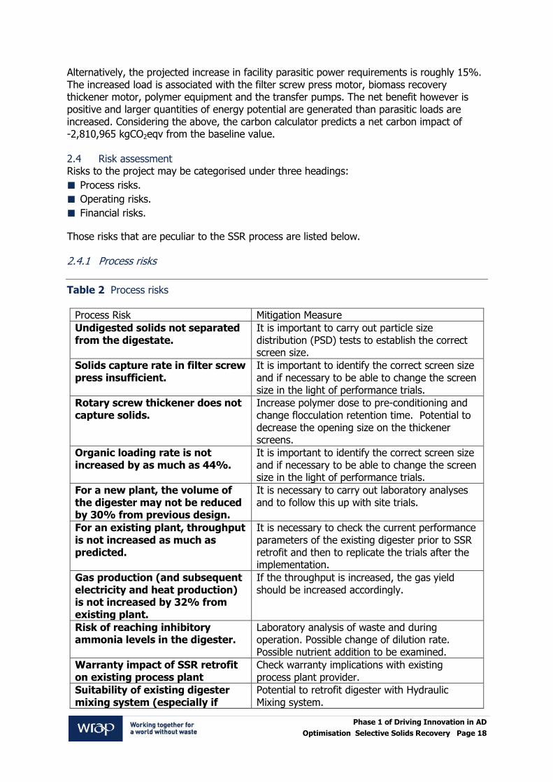
Those risks that are peculiar to the SSR process are listed below. 2.4.1 Process risks
Table 2 Process risks
Process Risk Mitigation Measure
Undigested solids not separated from the digestate.
It is important to carry out particle size distribution (PSD) tests to establish the correct screen size.
Solids capture rate in filter screw press insufficient.
It is important to identify the correct screen size and if necessary to be able to change the screen size in the light of performance trials.
Rotary screw thickener does not capture solids.
Increase polymer dose to pre-conditioning and change flocculation retention time. Potential to decrease the opening size on the thickener screens.
Organic loading rate is not increased by as much as 44%.
It is important to identify the correct screen size and if necessary to be able to change the screen size in the light of performance trials.
For a new plant, the volume of the digester may not be reduced by 30% from previous design.
It is necessary to carry out laboratory analyses and to follow this up with site trials.
For an existing plant, throughput is not increased as much as predicted.
It is necessary to check the current performance parameters of the existing digester prior to SSR retrofit and then to replicate the trials after the implementation.
Gas production (and subsequent electricity and heat production) is not increased by 32% from existing plant.
If the throughput is increased, the gas yield should be increased accordingly.
Risk of reaching inhibitory ammonia levels in the digester.
Laboratory analysis of waste and during operation. Possible change of dilution rate. Possible nutrient addition to be examined.
Warranty impact of SSR retrofit on existing process plant
Check warranty implications with existing process plant provider.
Suitability of existing digester mixing system (especially if
Potential to retrofit digester with Hydraulic Mixing system.

Phase 1 of Driving Innovation in AD
Optimisation Selective Solids Recovery Page 19
pumped mixing).
Seasonal variation on food waste composition.
Ensure process design envelope is adequately specified at inception. May be necessary to take samples for analysis during each season or at least simulate any known “spikes”.
2.4.2 Operational risks
Table 3 Operational risks
Operational Risk Mitigation Measure
Risk of not meeting the demonstration programme.
Check validity of financial offer from WRAP etc.
Quality of actual digester content changes from that sampled during trials.
Ensure representative sampling is carried out during design. Allow for adequate operating envelope.
Works shut down Ensure procedure for prolonged stoppage is well documented and implemented.
Too much grit in digester and interferes with SSR
Check tolerance of SSR to grit and adequacy of grit removal upstream.
Inadequate operation or maintenance of SSR kit.
Ensure good set of O&M instructions handed over and adopted by host.
2.4.3 Financial risks
Table 4 Financial risks
Financial Risk Mitigation Measure
Capital cost for a new plant is not reduced by 25%, even though the tank sizes are reduced.
Obtain more competitive price for tanks etc.
Overall operating cost is not reduced.
The operating cost will increase but as the throughput will increase the specific operating cost will decrease.
Revenue from sale of biogas or electricity and heat is not increased by 25%.
Check that correct Government incentive is used in financial model. Note that for food waste digestion the electricity generated from biogas attracts 2 ROCs/MWh but for sewage retrofit the incentive is only 0.5ROC/MWh.
Gate fee value significantly lower than the assumed value of £43/tonne, resulting in a lower return on investment.
Check actual gate fee that would be payable for additional plant feed and insert into financial model.
Risk of fluctuation of exchange rate
Check procurement strategy during implementation stage.

Phase 1 of Driving Innovation in AD
Optimisation Selective Solids Recovery Page 20
2.5 Risk conclusion In order to mitigate the risks listed above, it is necessary to carry out sampling and analysis of the digester contents. In particular, it is necessary to carry out analysis of the PSD. The PSD determines the sizes of the screen plates in the filters and therefore the apportionment of biomass solids for recycling. The risks may be further mitigated by carrying out trials on site. Anaergia is currently carrying out such site trials in order to validate the feasibility of retrofit at municipal waste water treatment plants in Canada, as well as the SWH Deerdykes food waste plant referenced in this report. When the SSR process has been demonstrated it will be possible to determine the improvements to the process parameters that may be guaranteed.

Phase 1 of Driving Innovation in AD
Optimisation Selective Solids Recovery Page 21
3.0 Legislation 3.1 Environmental permits, licences and exemptions In England and Wales, business activities that could have an impact on the environment and human health are regulated by a single framework under the Environmental Permitting (England and Wales) Regulations 2010. In Scotland and Northern Ireland, the same business activities are regulated by Pollution Prevention and Control (PPC) permits or Waste Management Licensing (WML). 3.1.1 Is the activity exempt or permitted? Scottish Water Horizons (SWH) has a permit to operate the AD plant at Deerdykes. The permit sets out a number of pre-defined standard rules, including throughput, output and nature of the material being digested as required by the Scottish Environmental Protection Agency (SEPA). 3.1.2 Will the invention/project have any implications on the use of outputs from a facility? Once the SSR process is in place, it is anticipated that the amount of digestate out will be reduced per unit volume of feed supplied. A small amount of cationic polymer will be used which will follow the path of the digestate through the process. The filtrate from both the SSR as well as the plant dewatering will continue to go through the existing post treatment. The biogas will be of the same quality but the volume of biogas will be increased due to the increase in feed to the system. 3.1.3 Will the invention/project change the status? If so how? Although the AD plant may operate within the existing performance standards of the existing permit when SSR is installed, SEPA (The Regulator) may require a variation to the existing permit, to account for a change to the operating parameters of the plant so they can be captured in the existing management processes e.g. Incident Prevention and Mitigation Plan. 3.2 Animal by-product Regulations (ABPR) Animal by-products (ABPs) are animal carcases, parts of carcases or products of animal origin that are not intended for human consumption. The following regulations detail the enforcement authorities, processes and procedures set out in the EC Regulations on ABPs.
Animal By-Products (Enforcement) (England) Regulations SI 2011/881.
Animal By-Products (Enforcement) (Wales) Regulations 2011.
Animal By-Products (Enforcement) (Scotland) Regulations 2011.
The regulations permit the treatment of low-risk (category 3) ABPs in approved composting and biogas premises. High risk (Category 2) ABPs cannot be used as feedstock in biogas plants, except where they have first been pre-treated to EU standards. B&V contacted the Animal Health and Veterinary Laboratories Agency (AHVLA) in order to establish if there were any issues with SSR technology if rolled out across the UK. The AHVLA could only comment on the general ABPs aspects. The AHVLA advised that, prior to installation, the plant would have to liaise with their local AHVLA office to consider the more practical implications of the system and the impact on their AD approval. The AHVLA considered that a retrofit system would require re-approval of the site as it may be a significant change to the system and critical control points (CCPs).

Phase 1 of Driving Innovation in AD
Optimisation Selective Solids Recovery Page 22
The basic requirements for biogas production from the ABPs perspective are that the systems must be fully enclosed and have no means of by-passing the pasteuriser, including condensate collection points. Sampling points should be present both after the pasteurisation point, and at storage. The system should have a HRT in excess of 18 days from pasteurisation entry for National Standards operations. (The ABP Regulations requires a minimum storage of 18 days post pasteurisation including HRT, reference PAS 110:2010 Specification for whole digestate, separated liquor and separated fibre derived from the anaerobic digestion of source-segregated biodegradable materials). The pasteuriser may be placed either before the digestion tanks (pre-pasteurisation) or after digestion (post-pasteurisation). If the plant post pasteurises, then any materials removed from the digesters during cleaning or maintenance are to be disposed of as the same ABP Category as the feedstock. In the Deerdykes case study, the feedstock is passed through the pasteurisation process prior to AD, so all the material is subject to pasteurisation. However, if SSR was to be retrofit to a food waste plant where pasteurisation was applied after digestion, then the rejected solids would be the same ABP Category as the feedstock. For the purposes of this study, we have assumed that the Deerdykes AD plant is operating in compliance with the ABP Regulations where the maximum particle size allowed is 12mm. Agglutination polymer is added at a concentration of 4-5kg per tonne TSS fed. From an ABP perspective it is necessary that the particle size in the digester is <12mm and so the extent to which the polymer causes clumping of the solids in the digester needs to be controlled. In general, AHVLA considered that the SSR process made a lot of sense and recognised the benefits but was not in a position to 'type approve' systems and each installation would need to be reviewed on a case by case basis taking into account management of the system on each site. AHVLA considered that it was important to control the streams of material coming out of the press and the separation of the materials so as to avoid bypass. 3.3 Duty of care The Duty of Care is a legal obligation which requires all persons involved with handling of waste to take all reasonable steps to keep waste safe. There is a legal responsibility to ensure that you produce, store, transport and dispose of waste without harming the environment. Anyone who handles waste must have the correct permit, license or exemption. The Duty of Care is set-out in the following regulatory framework in England, Wales and Scotland:
Environmental Protection Act 1990.
Control of Pollution (Amendment) Act 1989.
Waste (England and Wales) Regulations SI 2011/988.
Waste (Scotland) Regulations SSI 2011/226.
Waste Management Licensing (Scotland) Regulations SSI 2011/228.
3.3.1 What will be the duty of care implications associated with the invention/project? It is not anticipated that the production, storage and disposal of waste from the existing Deerdykes AD plant will change because the SSR process is designed to concentrate the existing digestate and does not change the waste feed. The filtrate from both the SSR process as well as the plant dewatering will also continue to go through the same post treatment.

Phase 1 of Driving Innovation in AD
Optimisation Selective Solids Recovery Page 23
A small amount of cationic polymer will be used in the SSR which will follow the path of the digestate through the process but this is not anticipated to change the digestates usage. 3.4 Operator competence In England and Wales operators must demonstrate their technical competence in order to obtain a permit to operate an AD plant under the Environmental Permitting (England and Wales) Regulations 2010. There are currently two approved schemes:
Chartered Institution of Wastes Management (CIWM) and the Waste Management Industry Training and Advisory Board (WAMITAB) Scheme.
Environmental Services Association (ESA) and the Energy and Utility Sector Skills Council (EU Sector Skills) Scheme.
In Scotland, there is no longer a legal requirement in Scotland for a Technically Competent Person to hold a Certificate of Technical Competence (COTC) under the Waste Management Licensing (Scotland) Regulations SSI 2011/228. However, it is considered that COTCs remain an appropriate qualification to demonstrate competence in Scotland and can be used on a voluntary basis. 3.4.1 Are there any implications from the invention/ project on operator competence? It is not anticipated that there will be an increase in Operator Competence standards after installation of the SSR process at Deerdykes. However, a regular analytical sampling practice will need to be carried out and maintenance will be required on the SSR skid, pumps and valves in accordance with the specific maintenance manual. 3.5 Health & safety Anaerobic digestion can be regarded as a chemical process with all the associated risks: Dangerous Substances and Explosive Atmospheres (DSEAR), fire and explosion, toxic gases, confined spaces, asphyxiation, pressure systems, Control of Substances Hazardous to Health (COSHH), etc. In addition, it also incorporates explosive gas handling and gas storage. Therefore, it is essential that thorough hazard and risk assessments are carried out at each stage of a project from design to installation to commissioning to implementation and operation. 3.5.1 What health and safety implications are associated with the invention/project? A polymer will be used during the implementation of the SSR system. This will require appropriate chemical handling and procedures which must be followed during operation. A Material Safety Data Sheet (MSDS) will be provided with the product, as well as specific standard operating procedures. In addition, an overall operation manual will be provided for the SSR system, which will include all maintenance requirements as well as necessary health and safety measures that are specific to the process and its equipment. Proper measures will need to be taken and will be addressed in the manual with respect to lock out / tag out, operator lifting and loading rates, removal of process piping contents and electrical safety amongst others. 3.6 Planning permission Planning permission is necessary for most new anaerobic digestion installations. Any installation accepting third party waste will need full planning permission. Small scale digesters using only on-farm waste may only require an Agricultural Notification. Specific planning concerns associated with new AD include site selection, odour control, traffic generation, landscape impact, noise, health and safety, security and lighting.

Phase 1 of Driving Innovation in AD
Optimisation Selective Solids Recovery Page 24
3.6.1 Will the invention/project have any implication on planning requirements? The SSR system at Deerdykes consists of pumps, valves, separation equipment, tankage and instrumentation, including a 3 phase electrical service and availability of potable water. The system will be provided as a skid mounted unit (pre-fabricated modular design) and can be located within a standardised container or a pre-fabricated building on a concrete pad. The installation of a new building would require planning permission from North Lanarkshire Council.
The SSR system is designed to concentrate the contents of the existing digester and does not change the feed. As solids are removed from the system separately from the digestate, care will be taken during the retrofit design to ensure that any potential odour release from these solids are contained so that odour nuisance may be mitigated. There is a possibility that traffic movements may increase slightly as a result of an increase in plant throughput, i.e. increase of delivery of feedstock and corresponding increase in land-spread of sludge product. The SSR system does not have high noise levels, especially if situated within an enclosure. However, the background noise levels of the site will need to be evaluated to determine the likelihood of noise disturbing local receptors (e.g. local residents), if present. 3.7 Quality protocol Quality outputs from anaerobic digestion include the whole digestate, the separated fibre fraction and the separated liquor. If the criteria in the Quality Protocol are met (including certification to PAS110), quality outputs from anaerobic digestion will normally be regarded as having been fully recovered. This means that in those circumstances the use of the fully recovered material may not require an authorisation. 3.7.1 Will the invention/project affect/improve the quality of the digestate? Solids that are removed from the system as part of the SSR solution may not have had sufficient residence time in the digester to satisfy the ABPR and so these solids will have to be kept separate from the solids that are extracted from the digester and that are dewatered for use as digestate in compliance with PAS110. It will be necessary to store these separately collected solids for at least 18 days in order to comply with PAS110. Alternatively, these solids could be disposed of as a waste as it would not comply with PAS110. 3.8 Excise duty If biogas is being used as a road fuel, the procedures to become compliant with HMRC for paying Excise Duty are all laid out in HMRC Notice 76. The biogas produced at Deerdykes AD is not used as road fuel and therefore this legislation is not applicable to this site. The biogas at Deerdykes AD is fed into a storage vessel before being fed into an onsite combined heat and power generation (CHP) unit. The heat produced is available for pasteurisation and heating the digester. The electricity is used to power plant, including the compost process. Any excess is exported to the grid.

Phase 1 of Driving Innovation in AD
Optimisation Selective Solids Recovery Page 25
4.0 Project site – Detailed technical appraisal of technology 4.1 Process description The SSR solution is designed to be applied either as a retrofit to an existing, single pass CSTR, or to be incorporated into a new build facility. In either case the design and operation of the SSR solution are similar. For this study, B&V/Anaergia has liaised with Scottish Water Horizons (SWH) to retrofit the technology on their site at Deerdykes. SWH has provided detailed information of their site in Scotland. The Deerdykes plant treats 35,000tpa of Category 3 food waste (e.g. supermarket waste, source segregated household food waste, commercial food waste i.e. ready meals factory waste, etc.) via AD. Based on this information, Anaergia has designed a proposed SSR for the site. The SSR process is designed to be a continuously operated system, by which digestate is continuously drawn and fed to the SSR process. Digestate is drawn utilising the SSR feed pump, from the digester. This pump is equipped with a variable frequency drive (VFD) such that the speed can be adjusted to maintain a pre-set flow. The digestate is initially fed to the UTS filter screw press (FSP). For the SSR solution, the FSP will be utilised to separate undigested solids from the digestate. Applying the FSP for this step will effectively dewater the digestate to between 22-25%, with a greater than 60% TSS capture rate. The FSP, shown in Figure 2, has been applied for more than 10 years in agricultural digester applications, to separate un-digested fibre material and large solids from the digestate.
Figure 2 UTS filter screw press
The dewatered cake from the FSP is either sent by gravity or conveyor to the plant dewatered cake facilities. The filtrate from the FSP will flow by gravity into a filtrate holding tank. From the filtrate holding tank, filtrate is drawn, utilising the FSP filtrate pump. The FSP filtrate pump is equipped with a VFD, again to maintain a pre-set flow rate, or in the case where the level in the filtrate holding tank is low, it can ramp down or shut off the pump. Filtrate is pumped towards the UTS biomass recovery thickener (BRT), shown in Figure 3. The BRT is designed so as to retain much smaller particle sizes and reach high solids capture rates in excess of 90%.

Phase 1 of Driving Innovation in AD
Optimisation Selective Solids Recovery Page 26
Figure 3 UTS biomass recovery thickener
Coupled with the key design attributes of screen opening, conveyance auger and outlet backpressure regulator, the BRT requires the addition of polymer in order to create a good floc of the solids heading into the BRT. The polymer used is a liquid emulsion, which utilises potable water in the make-up system. Once made up, the polymer is kept in the storage tank indicated for in-line dosing of the feed to the BRT, prior to the in-line mixing system. The feed into the BRT is a well-developed floc that is able to be dewatered from the 1-4% solids content of the feed, up to 12% solids. Within the BRT, the dewatering occurs in two phases; the first by gravity dewatering; the second under pressure, where a conical screw conveys the feed, with a reducing volume along the length as well as against a pressure of the outlet regulator. The filtrate from the BRT is collected in a filtrate holding tank, and is sent either by gravity or by pump to liquor storage tanks or treatment. Depending on the application, the filtrate could be used directly back at the head of the plant for dilution water. However, depending on the water analysis, further treatment may be necessary. In any application, this filtrate should be combined with the filtrate from existing dewatering facilities and treated in the same fashion. The captured thickened solids will then be sent back to the digester. In order to accomplish this, the solids outlet from the BRT falls directly into a feed screw conveyor into a positive displacement recovered biomass return pump. The return pump sends the thickened solids back to the digester. This return can either be combined with existing digester feed piping, or be fed separately into the digester either through an existing or new wall penetration. If a new penetration is made, it is recommended that the thickened solids return be fed in close proximity to the digester mixing system. The digester arrangement is unique to each installation. With much of the information presented in this report specific to the SWH plant. 4.2 Mass balance To estimate the benefits associated with implementing the SSR process, a mass balance model can be used. In general, AD mass balances model removal of COD, production of methane, balance of nutrients, volatile solids destruction and amount of digestate produced. In addition to these parameters, a mass balance that incorporates the SSR process must also focus on the distribution of solids, in particular the total suspended solids (TSS), volatile suspended solids (VSS) and biomass fraction of TSS. Added complexity is introduced by the

Phase 1 of Driving Innovation in AD
Optimisation Selective Solids Recovery Page 27
biomass recovery thickener stream that contributes to higher biomass, TSS and VSS concentrations in the digester. For preliminary estimation of the SSR performance and for development of the mass balance, certain assumptions were required. The assumed influent quality is presented in Table 5 below. To ensure accuracy of the model, laboratory analysis of the AD digestate and pasteurised influent has been initiated. The model will be updated to more accurately depict expected operating conditions when these parameters are available.
Table 5 Preliminary design parameters
Parameter Value Units
Digester Volume 4,000 m3
Influent flow rate 183 m3/d
HRT 21.9 days
TS 10.2%
VS 8.16%
Contamination Concentration 0.04%
TSS 100,000 mg/L
VSS 80,000 mg/L
COD 128,000 mg/L
sCOD 32,000 mg/L
pCOD 96,000 mg/L
Ammonia - N 2,228 mg N/L
The SSR process is also highly dependent on the particle size distribution (PSD) and fibre content of the digestate stream. As a result, two PSD profiles and fibre analyses have been initiated for digestate and pasteurised influent samples. For preliminary model development, a PSD for the food waste AD was assumed and is shown below in Table 6. In addition, capture rates for the respected particle size spectrums were assumed, based on experience. Paramount for the development of an AD mass balance when considering the SSR process, is the method for estimating the sludge yield and active biomass concentration. Here, the approach presented in Equation 1 and Equation 2 is applied. The growth yield coefficient, endogenous respiration coefficient and fraction of biomass remaining active during decay were selected to be 0.092 mg TSS/mg COD consumed, 0.024 d-1 and 80% respectively. The SRT was taken to be the specific retention time of the biomass after SSR. In the case of pre-SSR modeling, the SRT, HRT and specific retention time of the biomass are interchangeable.

Phase 1 of Driving Innovation in AD
Optimisation Selective Solids Recovery Page 28
Equation 1
( )
( )
Equation 2
( )
Where ⁄ ⁄
⁄
Table 6 Particle size distribution and the predicted capture rates for the FSP and the BRT
PSD profile of digestate
Type of solids
% solids within range
Total 0-75 µm 75-125
µm 125-250
µm 250-500
µm 500-1000
µm
TSS 18% 22% 10% 25% 25% 100%
VSS 18% 22% 10% 25% 25% 100%
Biomass 95% 5% 0% 0% 0% 100%
Contaminants 0% 40% 60% 0% 0% 100%
Filter Screw Press
% Capture Solids
Total 0-75 µm 75-125
µm 125-250
µm 250-500
µm 500-1000
µm
Filter Capture Rate 10% 15% 55% 95% 100%
TSS Capture Rate 1.8% 3.3% 5.5% 23.8% 25.0% 59.4%
VSS Capture Rate 1.8% 3.3% 5.5% 23.8% 25.0% 59.4%
Biomass Capture
Rate 9.5% 0.8% 0.0% 0.0% 0.0% 10.3%
Contaminant
Capture Rate 0.0% 6.0% 33.0% 0.0% 0.0% 39.0%
PSD profile of FSP filtrate Type of Solids
% solids within range
Total 0-75 µm 75-125
µm 125-250
µm 250-500
µm 500-1000
µm
TSS 40% 46% 11% 3% 0% 100%
VSS 39.9% 46.0% 11.1% 3.1% 0.0% 100%
Biomass 95.3% 4.7% 0.0% 0.0% 0.0% 100%
Contaminants 0.0% 55.7% 44.3% 0.0% 0.0% 100%

Phase 1 of Driving Innovation in AD
Optimisation Selective Solids Recovery Page 29
Biomass Recovery Thickener
% Capture Solids
Total 0-75 µm 75-125
µm 125-250
µm 250-500
µm 500-1000
µm
Filter Capture Rate 60% 70% 95% 100% 100%
TSS Capture Rate 23.9% 32.2% 10.5% 3.1% 0.0% 69.7%
VSS Capture Rate 23.9% 32.2% 10.5% 3.1% 0.0% 69.7%
Biomass Capture Rate 57.2% 3.3% 0.0% 0.0% 0.0% 60.5%
Contaminant.Capture
Rate 0.0% 39.0% 42.0% 0.0% 0.0% 81.1%
To achieve a baseline for the current AD operation, a mass balance was performed for the feedstock presented in Table 5. Model results were contrasted with the current performance of the anaerobic digestion facility with excellent consistency. In particular, VS destruction of 69.6% was predicted in the model, with reported VS destruction of 70%; 57 m3 of biogas per m3 of feedstock was predicted by the model with a value reported of 62 m3 of biogas per m3 of feedstock; a loading rate of 5.9 kg COD/m3/d was predicted by the model with a value of 6 kg/m3/d reported; and 78% of COD was predicted to be converted to methane by the model with an actual value of 79% reported. A synopsis of the mass balance for the current operation is presented in Figure 4. With the calibrated model, the SSR process was modelled to predict potential increased loading capacity. Pre-SSR implementation, the AD was operating at an F/M ratio of 0.80 kg COD/kg biomass/d (0.15 kg VS/kg VSS/d). With implementation of an SSR process, operating at 160 m3/d, a 30% increase in feedstock throughput is achievable, without compromising the F/M ratio. As a result, methane production is expected to increase by 32%, while inhibitory effects of ammonia might not be an issue. A summary of the mass balance considering implementation of the SSR process is shown in Figure 5.
Figure 4 Model results for AD without considering SSR design

Phase 1 of Driving Innovation in AD
Optimisation Selective Solids Recovery Page 30
Figure 5 Model results for AD with incorporation of the SSR design
4.3 Site survey SWH completed a questionnaire regarding plant design, operating data and operational cost data for its Deerdykes organic waste treatment plant. In addition, SWH has provided the following documents:
Process flow diagrams.
Process and instrumentations diagrams.
Mass balance.
4.4 Specification The plant specification has been generated based on data provided by SWH, i.e. process flow diagrams (PFD), mass balance and P&IDs. 4.5 Programme Upon successful securing of all funding, the anticipated time frame to implement the SSR demonstration and monitoring period is outlined in Figure 6 Demonstration phase programme
. The first activity would be to obtain a set of representative samples and send these for analysis. The results of these analyses should confirm the assumptions on, e.g. PSD that have been made in this report. The process design would be confirmed and then, if necessary, bench tests would be carried out. On completion of the bench tests, the engineering phase would be carried out. The periods necessary for engineering, procurement and construction are listed Table 7. These activity durations are incorporated in Figure 6 Demonstration phase programme

Phase 1 of Driving Innovation in AD
Optimisation Selective Solids Recovery Page 31
. The design of the demonstration project is well developed at this development stage. The detailed engineering would be carried out during the detailed engineering phase of the project, when all process parameters have been confirmed. Whereas all the aspects and variables that might impact the project have been considered, they have not necessarily been finalised at this stage. B&V is used to this approach and would normally approach such a project in a systematic way so that progress may be continuous and measurable.
Table 7 Programme
Activity Duration
Pre-equipment purchase engineering 12 weeks
Equipment procurement, skid fabrication, site
tendering, site preparation 15 -18 weeks
Equipment installation 4 weeks
SSR commission and demonstration start-up 6 weeks
Demonstration monitoring period 1 year
B&V believes that the above timescales and milestones are realistic, are typical of this kind of project and should therefore result in a successful project delivery. B&V is confident that provided this systematic approach is adopted, the project will be delivered in a timely manner and result in a commercially representative demonstration of the technology. 4.6 UTS reference site visits B&V has a significant track record in the delivery of waste water treatment plants in the UK and has elected to work closely with Anaergia UTS on this project as UTS has the necessary level of technical competency to execute this project. Throughout Europe, UTS has over 1,700 biogas reference plants, where either turnkey solutions have been provided, or UTS has supplied proprietary equipment. These plants are operated on various feed substrates, including energy crops, manure, other agricultural wastes and food waste. At these facilities, UTS biogas technologies are on display, including the FSP. During future phases of the project, site visits to pertinent facilities can be arranged and coordinated through the local UTS office.

Phase 1 of Driving Innovation in AD
Optimisation Selective Solids Recovery Page 32
Figure 6 Demonstration phase programme

5.0 Economic Cost Benefit Analysis2 Four sections have been included with respect to economic analysis. In section 5.1, the scenario of incorporating the SSR system into a newly built plant is considered, and the reduction in capital investment cost is evaluated. In section 5.2, the scenario of incorporating the SSR system as a retrofit solution, to increase plant capacity is considered, whereby the cost of installing the SSR system is compared to the payback for additional biogas generation. Sections 5.3 and 7.4 discuss the Capex and Opex costs associated with the demonstration of the SSR system which would occur in Phase II of this project. It should be noted that Capex and Opex costs will differ in the demonstration sections compared to the economic analysis sections, as certain provisions for contingency as well as additional operational work associated with a demonstration are considered. 5.1 Capex – New build applications As mentioned in previous sections, by incorporating the SSR system into a new build anaerobic digestion system for organic food waste applications, its inclusion could have a significant beneficial impact on the capital costs per unit capacity. Inclusion of the SSR system will have an effect on the capital cost of the digester and associated site and civil works, as well as reducing, or potentially eliminating the size of alternative dewatering facilities. For the purposes of comparison, the Deerdykes plant was used for reference, which has a digester volume of 5,300 m3. Additionally, the Deerdykes plant has both acid phase and pasteurisation treatment steps prior to digestion, which have been factored into the plant cost. The impact of incorporating the SSR system effectively reduces the volume of the digester by 30%, which is a conservative estimate considering mass balance modelling of this application has shown that up to a 44% increase in OLR could be achieved with the inclusion of the SSR. Additionally, it is seen that the plant dewatering facilities could be reduced in size by 50% as a minimum. This is based on the fact that large particles in the digestate are being removed by the FSP in the first stage of the SSR system. In order to accurately model the costs of a new build system the Triton digester from UTS was utilised. For digesters of the capacity included in this evaluation, the Triton digester design is considered to be the most economical overall, as the tank within a tank design reduces the aspect ratio to which mixing must be applied. Additionally, the alternative would typically be to build two digesters, which the Triton design eliminates and allows for tank walls to be shared. This design practice significantly reduces digester tank costs. Figure 7 depicts the Triton digester design.
2 WRAP - Please note that all costs provided may no longer be representative but were correct on receipt of the report in 2012.

Phase 1 of Driving Innovation in AD
Optimisation Selective Solids Recovery Page 34
Figure 7 Triton digester
As can be seen from the costing summary in Table 8, the total Capex savings resulting from the inclusion of the SSR system is £1.28 million, which is approximately a saving of 8%. The main areas in which savings may be realised are on the digester system as well as on solids handling. In this analysis, equipment selling prices were marked up and a 15% contingency was included in the costing. The equipment costs utilised in this case study were drawn from the UTS/Anaergia database of equipment pricing, which has been quoted by equipment suppliers to UTS/Anaergia as an Original Equipment Manufacturer (OEM) customer. These values are utilised by UTS/Anaergia to develop budgetary and final proposals in response to sales inquiries. In order to estimate the fully burdened cost, equipment costs were factored to account for installation costs, additional piping/mechanical costs, electrical, controls and instrumentation. Additionally provisions for site works and concrete were included and based on the plant size, in particular the digester volume. Added to the sub-total of all the above mentioned costs were provisions for contractor mobilisation and insurance, general conditions, profit, in-situ engineering, bonds and construction management

Phase 1 of Driving Innovation in AD
Optimisation Selective Solids Recovery Page 35
Table 8 Capital cost comparison with SSR
Capital Cost based on 5,300 m3 Digester Solution
(£)
Capital Cost based on 3,710 m3 Digester
Solution (£)
Pre-Treatment £ 2,922,000 £ 2,922,000
Gas Handling & CHP £ 3,256,000 £ 3,256,000
Triton Anaerobic Digester System £ 5,615,000 £ 4,253,000
Solids Handling £ 1,920,000 £ 1,282,000
SSR System - £ 879,750
Sub Total £ 13,713,000 £ 12,592,750
Engineering & Project Management –
15% £ 2,056,950 £ 1,888,912
Total £ 15,769,950 £ 14,481,662
% Potential Savings 8%
In this scenario, no change to plant operating costs is considered. Although the SSR system equipment must be included in terms of electrical load and maintenance, the solids handling (dewatering) system is much smaller. 5.2 Retrofit applications – operating revenue benefit When the SSR system is considered for retrofit situations, the objective is to increase the OLR of the plant, thus generating increase production of biogas and a subsequent increase in electricity and heat generation. For the case study conducted on the Deerdykes facility, the inclusion of the SSR system allows for the OLR to be increased by greater than 30%, while still maintaining the same healthy F/M ratio. For feasibility analysis, the cost as outlined in section 5.1 is £878k. Its inclusion however allows for a 30% increase in OLR, which in turn produces an additional 3,357 m3 biogas per day. This, when sent to a CHP unit, results in an additional 373 kW of electricity. It is estimated that 25 kW is required for the SSR, hence when this is subtracted from the additional electricity generated, a total annual benefit of 2,835 MWh3 can be seen. Based on revenue from selling electricity at 9.9 p/kWh, the annual revenue benefit is £280,674. Furthermore, plant owners would realise additional gate fees from the increased quantity of feedstock accepted. Based on a gate fee of £ 43/tonne4, the annual revenue would be £ 451,500. Under the current UK government incentives a plant generating electricity from food waste via AD is entitled to get 2 ROCs/MWh. Assuming a ROC value of £46/MWh and applying a pass-through charge of 10%, the plant will receive and additional £234,745. To counter the increased revenue, inclusion of the SSR system as well as additional CHP capacity are projected to have operating costs of £ 53,500 and £ 68,000 respectively. Additionally, as indigestible solids will be removed as part of the SSR process, the potential exists that these solids
3 Assuming 93% availability
4 Gate fee based on median gate fee for AD – www.letsrecycle.com

Phase 1 of Driving Innovation in AD
Optimisation Selective Solids Recovery Page 36
will not have resided in the digester for a period of 18 days, which is required to achieve a PAS 110 digestate. As such, additional storage is required for these indigestible solids. The estimated capital cost associated with this additional storage is c.£79k. Finally, in order to capture the potential of additional equipment costs associated with handling the increased capacity of biogas (outside of the added CHP), a contingency of 15% of the additional capital costs has been considered, which amounts to £ 270,000.
Table 9 SSR payback and IRR analysis – Retrofit
Item Amount
SSR Capital Cost (Installed) £ 879,750
Additional CHP Engine £ 950,000
Additional Storage for indigestible solids £ 79,000
Contingency for increase capacity – 15% £ 270,000
Additional Electricity Generated 373 kW
Additional Electricity Generated* 3,038,756 kWh/year
SSR Electrical Requirements 25 kW
SSR Electrical Requirements* 203,670 kWh/year
Resultant Net Electricity Benefits 348 kW
Resultant Net Electricity Benefits * 2,835,086 kWh/year
Net Annual Revenue from Electricity Increase £ 280,674 pa
ROCs £ 234,745 pa
Additional Gate Fees £ 451,500 pa
Net SSR Annual Operating Costs** £ 110,000 pa
CHP Engine Opex £ 68,000 pa
Net Annual Revenue Benefit £ 788,919 pa
Simple Payback 2.8 Years
Note:
*Assuming 93% availability
**Excludes digestate disposal costs as assumed PAS110 and hence has residual
value
5.3 SSR system capital costs for demonstration The SSR solution will come as a skid mounted system with both separation steps, including all pumps and polymer unit. Included in the skidded system will also be all valves and piping, instrumentation, electrical wiring and control boxes. The SSR skid will be operated by an independent control system that can function as a stand-alone unit or be tied into plant controls. The SSR skid will draw digestate from either the digestate transfer line, or from the storage tank where used. Outputs from the SSR skid include:
a) dewatered solids from the first stage of separation that will be directed and tied into the
solids outlet of existing plant dewatering facilities;
b) filtrate from both the first and second stages of separation, tied into plant dewatering
centrate handling; and

Phase 1 of Driving Innovation in AD
Optimisation Selective Solids Recovery Page 37
c) recovered biomass and fines, which are pumped back to the digester, in most cases
through existing digester nozzles.
The SSR solution will be delivered skid mounted and so most of the fabrication and manufacturing will occur prior to the solution arriving at the site. The major steps involved with implementing the SSR solution for a specific application are itemised below:
a. Detailed process design and SSR sizing, specific to the site installation and the type of
substrate.
b. Laboratory testing for BRT polymer selection and FSP optimal screen opening
determination.
c. Component selection, skid sizing and equipment procurement.
d. SSR skid fabrication and assembly (mechanical, electrical, and controls).
e. SSR skid control PLC programming and factory testing. (With the potential to include
remote diagnostic monitoring of the SSR performance, from the vendor’s control centre; to
ensure best performance as an added value service).
f. Site installation contractor selection and mobilisation.
g. Site preparation and civil works for SSR skid siting.
h. SSR skid shipment to site and locating on new equipment pad.
i. Skid electrical and mechanical hook-ups.
j. Cut ins of SSR process lines to operating process flow, (may require temporary halting of
digester operations).
k. Start SSR skid, slowly building up treatment and subsequent biomass recovery rate,
coupled with increasing the loading rate of the digester.
The estimated capital costs of the SSR system for demonstration are £879,750. A contingency has been applied as the laboratory tests could not be completed in the time available although it is not expected that changes arising from the results would result in significant costs. Additionally, the contingency for plant modifications to handle additional biogas has been considered: for example, the increase in capacity of the biogas derived and the energy recovery plant. An allowance has been made for the increased storage that would be required for solids extracted from the process to ensure that these solids still comply with the requirements of the ABPR. A breakdown of these estimated capital costs is included in Error! Reference source not found. below. It should be noted that Anaergia has recently built a skidded system for its Rotary Screw Thickener in the Omnivore application. Equipment utilised in the SSR system is similar to this built system, and as such the accuracy of the equipment costs is high. Typical provision factors for installation, site work and construction have been taken. Additionally, a contingency of 15% has been included in the estimate. Certainly, the SSR solution offers improvements in efficiency and reduced capital cost and is therefore suitable. For the retrofit application, the SSR offers the host the opportunity for increased revenue from the existing asset by expending a relatively minor capital outlay. There is the added attraction of a good simple payback on the investment; the plant may be supplied on skids, allowing a short period of construction on site with minimal disruption; the plant has a small footprint allowing it to

Phase 1 of Driving Innovation in AD
Optimisation Selective Solids Recovery Page 38
be accommodated within the existing plant. The SSR solution may be retrofitted across a wide range of AD facilities and so savings in engineering costs may be realised. For the new plant application, the SSR solution allows an improved return on investment through a reduced capital investment as the tank sizes may be reduced. 5.4 SSR operating costs for demonstration It is useful to accurately track the digester F/M ratio before and after implementation of SSR. To do so, an accurate methodology is used to measure the active biomass fraction of the volatile suspended solids. The biogas production must be monitored to indicate the volatile solids destruction rate associated with the measured F/M ratio. Prior to the implementation of SSR, the digester F/M ratio must be tracked for an adequate period of time in order to develop a stable and repeatable digester value. Once in operation, digester F/M measurements, as well as biogas production monitoring must continue at regular intervals to determine what biomass recovery rate is achieved. The method to be used to monitor volatile solids is the typical test method to measure volatile solids in a liquid matrix. The standard reference is APHA 2540B. To measure active biomass, a measurement of the digester ATP must be performed. ATP stands for adenosine triphosphate, a molecule only seen surrounding living organisms. Testing digester contents for ATP will give an accurate measurement of living (active) biomass. During regular operation of the SSR solution, the amount of biomass recovered will be adjusted based on the measured F/M ratio, to try to maintain the determined healthy value prior to SSR implementation but at an increased OLR. In addition to maintaining regular analytical sampling practice as described above, maintenance is required on the SSR skid, typical of mechanical equipment. All pumps and valves will require maintenance in accordance with the specific maintenance manual. For the UTS FSP and the UTS BRT, the screen media within each unit must be inspected each month. The demonstration will have annual operating expenses associated with its operation and performance analysis.

Phase 1 of Driving Innovation in AD
Optimisation Selective Solids Recovery Page 39
6.0 Application in the UK Assuming the demonstration is successful and creates a more cost effective AD and the benefits can be truly demonstrated, then Anaergia with B&V will aim to develop and commercialise a solution and service to retrofit enhancement solutions to existing AD plants. B&V and Anaergia intend to build a business transferrable around the globe to enhance energy security, carbon reduction, and sustainable waste disposal (reuse). This will aim to create economic benefit and employment opportunities. We expect commercialisation to be a real opportunity. The combination of UTS/Anaergia and B&V provides tremendous global reach into installation opportunities. UTS/Anaergia has an established installation base of over 1,700 biogas plants, with over 250 of those being turn-key. Similarly, B&V is recognised globally as an expert at providing engineering services and turnkey solutions for anaerobic digestion applications of all organic waste streams. From an offering perspective UTS/Anaergia will incorporate the SSR system into its Helios and Triton digestion systems. Once commercialised, market penetration will occur on two fronts where a) both UTS/Anaergia will assess existing plant installations for prime candidates for retrofit, and b) new build opportunities where the beneficial impacts of SSR can be seen. To support both of these fronts, system marketing material will be generated, and circulated to key players in the anaerobic digestion marketplace. Additionally, the successful case study of the Deerdykes plant will be published in pertinent industry papers and technical conferences. Based on the above approach, it is reasonable to project that within 3 years of commercialisation, 5 plants will be equipped with SSR technology. Looking longer term, a reasonable target of 30 plants in the 5-7 year timeframe from commercialisation is plausible. In terms of Intellectual property protection, Anaergia has filed multiple patent applications globally surrounding the SSR process. Additionally, the design and function of both the FSP and BRT are protected by both patents as well as some trade secrets. Anaergia has developed a similar application for wastewater treatment plants: “Omnivore”. The system is based on the same principles as explained in section 2.0. Conventional municipal wastewater sludge anaerobic digesters are sometimes inefficiently used throughout the UK. Only a fraction of the actual digestion and biogas generation capacity of the existing tank volumes is realised with the current operation mode. This solution addresses limitations of conventional sewage sludge anaerobic digestion by converting conventional digesters to high solids anaerobic digesters by increasing the solids content in the digester 2 to 3 times.

Phase 1 of Driving Innovation in AD
Optimisation Selective Solids Recovery Page 40
7.0 Conclusions and recommendations 7.1 Conclusions The SSR solution is designed to be applied either as a retrofit to an existing single pass CSTR, or to be incorporated into a new build facility. In either case the design and operation of the SSR solution are similar. For this study, B&V/Anaergia has liaised with Scottish Water Horizons (SWH) to retrofit the technology at their organics waste facility at Deerdykes. When considering new build applications, when incorporating SSR, not only will the digester operational benefits and increase in capacity be seen, but also the SSR system will reduce the size and potentially even eliminate the need for separate dewatering equipment. The SSR retrofit plant will be provided as a skid-mounted system (pre-fabricated modular design) and can be located within a standardised container or a pre-fabricated building on a concrete pad. The installation of a new building (where required) would require planning permission from the local council. The SSR separation equipment utilises very low energy and polymer consumption compared to other technologies such as dissolved air flotation, membrane separation or other rotary drum thickeners. Operationally, the BRT has a key advantage over other mechanical separation technologies, as it requires a very low polymer dosage rate (less than 4 kg/tonne solids), as well as very low operational energy. Because a two stage separation system is employed, more readily degradable volatile solids and biomass are retained, compared to where general recuperative thickening is employed, which would retain essentially all solids. The potential to increase the volatile solids destruction is feasible as the readily degradable material is preferentially retained. With the implementation of an SSR process operating at 160 m3/d, a c.30% increase in facility feedstock is achievable without compromising the F/M ratio. As a result, methane production is expected to increase by c.32% while inhibitory effects of ammonia may not be an issue. The impact of incorporating the SSR system effectively reduces the volume of the digester by 30%. This is a conservative estimate: mass balance modelling of this application has indicated up to 44% increase in OLR could be achieved with the SSR inclusion. The total Capex savings that could have been realised by including the SSR system for a new build plant is £1.28 million, which is approximately a saving of 8%. For the case study conducted on the Deerdykes facility, the inclusion of the SSR system allows for the OLR to be increased by greater than 30%, while still maintaining the same healthy F/M ratio. The capital cost of the retrofit of the SSR would be c. £ 880k with a simple payback of 2.8 years. 7.2 Recommendations B&V recommends that several operating conditions and parameters be determined prior to employing SSR, whether this is for food waste or for municipal sludge applications. The key conditions which needed to be determined are:

Phase 1 of Driving Innovation in AD
Optimisation Selective Solids Recovery Page 41
a. Required pre-conditioning steps including requirements for polymer dosing, dispersion
pressure as well as flocculation time.
b. BRT screen opening size and segment length to maximise the use of gravity dewatering
and subsequent pressing.
c. Achievable solids loading rates.
For all of these parameters, laboratory testing should been completed to determine these. Currently, full scale equipment validation testing is on-going throughout the summer of 2012. Assuming the demonstration is successful and creates a more cost effective AD and the benefits can be truly demonstrated, then Anaergia with B&V will aim to develop and commercialise a solution and service to retrofit enhancement solutions to existing AD plants. B&V and Anaergia intend to build a business transferrable around the globe to enhance energy security, carbon reduction, and sustainable waste disposal (reuse). This will aim to create economic benefit and employment opportunities. We expect commercialisation to be a real opportunity and look forward to WRAP’s continued involvement in Phase 2 of this project.

Phase 1 of Driving Innovation in AD
Optimisation Selective Solids Recovery Page 42
8.0 References Animal By-Products (Enforcement) (England) Regulations SI 2011/881. The Animal By-Products (Enforcement) (Wales) Regulations 2011. The Animal By-Products (Enforcement) (Scotland) Regulations 2011. Environmental Protection Act 1990. Control of Pollution (Amendment) Act 1989. Waste (England and Wales) Regulations SI 2011/988. Waste (Scotland) Regulations SSI 2011/226. Waste Management Licensing (Scotland) Regulations SSI 2011/228. PAS 110:2010, Specification for whole digestate, separated liquor and separated fibre derived from the anaerobic digestion of source-segregated biodegradable materials Coleman, P (2012). “Anaerobic Digestion – Comparison of Design Considerations Between a Biosolids and Organic Solid Wastes Digestion Facility”, WEAO Conference, Ottawa, Canada.

Phase 1 of Driving Innovation in AD
Optimisation Selective Solids Recovery Page 43
www.wrap.org.uk/diad