Embed Size (px)
Citation preview

Feasibility of Demonstrating PPT’s on FalconSAT-3
C1C Andrea JohnsonUnited States
Air Force Academy

Outline
Problems encountered with PPT’s Methods of demonstrating use
Spiral Transfer Attitude
Model Experimental Results Recommendations

Problems Encountered Low Thrust
160e-6 N maximum thrust 15e-6 second pulse, 2 Hz => 4.8e-9 N
average thrust Updated data indicates possibly higher
average thrust (50 μN-s) Power requirements Inaccuracy of original model
Uncoupled equations of motion Inaccurate disturbance torque models
Methods of Demonstrating
Spiral Transfer One PPT yields 1.6 cm change in
semimajor axis with no disturbance torques
No GPS receiver

Methods of Demonstrating Cont.
Attitude Control Z-axis only possibility for control
because of small moment of inertia (1.31 versus 67.4 kg-m2)

Model
Assumptions Equations of motion PPT modeling Disturbance torques Validation

Assumptions
Simplified satellite model Small center of pressure - center of
mass offset No products of inertia Constant, known PPT decay rate Negligible orbital perturbations

Assumptions Cont.
31.100
069.30
0064.3
31.100
045.670
0040.67
Body Mass: 35.5 kg
Boom Mass (without tip mass): 3.15 kg
Tip Mass: 7.45 kg
Total Mass: 46.1 kg
Inertia Tensor (Stowed Boom):
kg-m2
Inertia Tensor (Deployed Boom):
kg-m2
Coefficient of Drag (Cd): 2.6
Spacecraft Dipole: 0.05 A-m2
Orbit: Altitude = 560 kmSemimajor axis = 6938.137 kmInclination = 35.4o
Eccentricity = 0Right Ascension = 0o

Equations of Motion
1322311 )( TIII
2313122 )( TIII
3211233 )( TIII

PPT Modeling
t
15 usec 15 usec4.8 nNs
160 μN
t4.8 nN
Actual
Simulation1 sec

Disturbance Torques
Gravity Gradient Magnetic Drag Solar Pressure
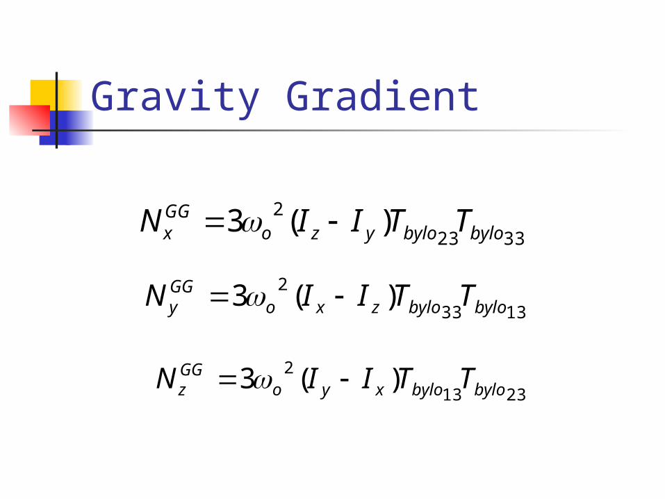
Gravity Gradient
3323
2 )(3 bylobyloyzoGGx TTIIN
1333
2 )(3 bylobylozxoGGy TTIIN
2313
2 )(3 bylobyloxyoGGz TTIIN

Magnetic
13th degree, 13th order IGRF 10th generation model with
secular terms up to 8th degree and 8th order

Magnetic Cont.
k
n
n
m
mnmnmnn
r Pmhmgnr
a
r
VB
1 0
,,,2
sincos1
k
n
n
m
mnmnmn
nP
mhmgr
aV
rB
1 0
,,,
2
sincos1
k
n
n
m
mnmnmnn
Pmhmgmr
aV
rB
1 0
,,,2
cossinsin
1
sin
1

Magnetic cont.
sincoscossin BBBB rx
cossincossin BBBB ry sincos BBB rz
x
y
z
θ
r
φ
Magnetic Cont.
ECF to ECI coordinate frame conversion
Precession Nutation Sidereal time Polar motion

Drag
VVNAVCF dplanedragˆˆˆ
2
1 2,
VVZDLVCF dcylinderdragˆˆˆ1
2
1 22,
n
iiidrag FRN
1
Solar Pressure
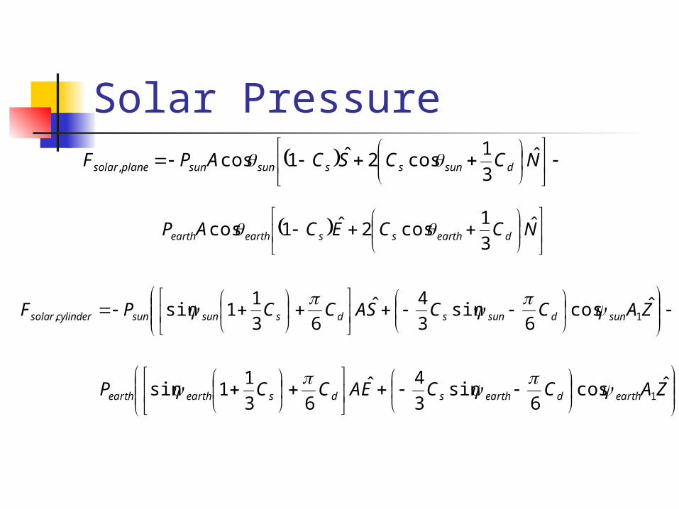
NCCSCAPF dsunsssunsunplanesolar
ˆ3
1cos2ˆ1cos,
NCCECAP dearthssearthearth
ˆ3
1cos2ˆ1cos
ZACCSACCPF sundsunsdssunsuncylindersolar
ˆcos6
sin3
4ˆ63
11sin 1,
ZACCEACCP earthdearthsdsearthearth
ˆcos6
sin3
4ˆ63
11sin 1

Validation Integrator: Attitude and orbital
energy and momentum should be constant
Gravity gradient: Should match C program data
Magnetic field: Should match C program data
Drag and solar pressure validated using hand calculations

Integrator Energy and momentum constant if no
external torques Attitude
Orbit
Normalized error
I Ih T
2
1
R
V 2
2
VRh
o
o t
o
o
h
thh

Integrator: Attitude
Energy Momentum
Maximum error: 3e-14 Maximum error: 1.5e-14

Integrator: Orbit
Energy Momentum
Maximum error: 2.5e-14 Maximum error: 7.5e-15

Gravity Gradient Validation
-1.5
-1.0
-0.5
0.0
0.5
1.0
1.5
1 JanJan 70
2 Fri
UoSat: Attitude Log File
Time
Roll Angle Pitch Angle Yaw Angle

Gravity Gradient Validation Cont.

Magnetic Field Validation
Magnetic field in ECF matched C program numerical output
8th degree, 8th order With secular terms
ECF to ECI conversion output matched C program

Estimation Theory
Kalman filter Truncate results Statistical mean smoother
Batch estimator Data used by filters comes from
attitude determination Kalman filter

Estimation Theory Cont.
xyyxbylobyloxyozz BMBMTTIII 2313
23
gkNNNII PPTo
solarz
dragzyxxy z
yxbylobylooxyzz TTIIIz 2313
23ˆ
gkNNNBMBMz PPTo
solarz
dragzxyyx z
gkNN PPTo
PPTz z

Estimation Theory Cont.
y
x
PPTo
M
M
N
Xz
yx M
z
M
z
N
zH
xy BBH 1

Batch Filter Algorithm
k
kTkT
R
HHWHH
k
kkTkT
R
zzHCOWH
ˆ
xy BBH 1

Batch Filter Algorithm Cont.
COWHWHHX TT 1
XXX
If X (user defined), then exit the loop. If not,

Experimental Results
No Noise Actual
PPT torque 0.0000
Dipole (x) 0.0000
Dipole (y) 0.0500
Percent Error Kalman w/o Smoothing
Percent Error Kalman w/ Smoothing
Percent Error Batch
N/A N/A N/A
N/A N/A N/A
3.4001E-10 8.6001E-10 0.0000E+00

Experimental Results Cont.
0.3E-6 on B field Actual
PPT torque 0.0000
Dipole (x) 0.0000
Dipole (y) 0.0500
Percent Error Kalman w/o Smoothing
Percent Error Kalman w/ Smoothing Percent Error Batch
N/A N/A N/A
N/A N/A N/A
2.0709 2.2331 0.0318

Experimental Results Cont.
No PPT's With PPT's
Noise Percent error Noise Percent error
0.3E-3 on w 0.379488 0.3E-3 on w 10.07
1.33E-6 on wdot 0.379488
1.33E-6 on wdot 10.07

Experimental Results Cont. Batch filter is more accurate with and
without noise for longer firing times Kalman filter converges faster for short
firing times, but has comparatively poor accuracy

Recommendations 24 hour firing Magnetorquers and non-essential
systems off Magnetometer readings are taken or
IGRF data provided Attitude data for the entire firing period
is taken Initialize attitude determination Kalman
filter at the start of firing and provide batch filter data only after convergence

Questions?