Embed Size (px)
Citation preview

FE Analysis of Firearm Locking Systems
Lorenzo Castiglioni
Fabbrica D’armi Pietro Beretta S.p.A.
Abstract: In a firearm the firing cycle is a high-speed dynamic event, of short duration (a few milliseconds) and highly non-linear - large displacements, plasticity, contact - during which its components are subjected to pulse loads - high-pressure and temperature gas and impact between moving parts. In the design of any firearm choosing the locking (breech) system is the fundamental starting point as this will guarantee that the cartridge case is adequately supported to withstand the tremendous rearward thrust exerted by the powder gases. The breech system consists of a group of high strength components – barrel, bolt, receiver, locking devices, etc. – the task of which is to keep the rear portion of the barrel closed for a certain time period, until the pressure of the powder gases has dropped to an operating limit at which the breech may be opened safely for completing the firing cycle. After this time period an automatic firearm performs the other functions - unlocking of the bolt, extraction and ejection of the spent cartridge case, loading of a fresh cartridge and locking of the bolt - utilizing the impulse of gas pressure to impart a velocity to the movable parts. It is the purpose of the present work to illustrate, through some practical applications, the integration of Test and ABAQUS as a convenient approach for the rational and conscious (numerical) design of the locking system, while indicating the potential and also the limitations both from the mechanical strength and the movable part dynamics points of view. Keywords: Barrel, Breech, Cartridge Case, Combustion, Contact, Firearm, Gas Pressure, Locking Device, Projectile, Propellant, Receiver and Viscoplasticity.
1. Introduction
In general a firearm during its operating cycle will be subjected to pulse loading generated by high-pressure (500-5.000 bar) and temperature (2.000°K) gases resulting from the combustion of the powder charge in the cartridge. Impacted by the firing pin the primer ignites the propellant and the combustion converts the chemical energy of the charge into kinetic and potential energies of the firearm-ammunition assembly in a very short time period (500-3.000 microseconds). The state of the thermo dynamical system also depends on the projectile movement. At the beginning of ignition the boundary consists of the cartridge case wall and the base of the projectile and then extends to the barrel inner wall (bore). The cartridge case is supported radially by the barrel chamber and axially by the rear closing of the barrel (breech). Detail is seen in Figure 1.
2008 Abaqus Users’ Conference 1
Visit the SIMULIA Resource Center for more customer examples.
Visit the SIMULIA Resource Center for more customer examples.

Figure 1. Small arms chamber containing cartridge.
A After a time period commencing at the moment of the exiting of the projectile from the barrel muzzle the gas pressure and temperature fall to a level where at the receiver can be safely opened to permit the subsequent firing cycle operations: unlocking, extraction and ejection of the spent cartridge case, the feeding of a fresh cartridge and locking of the breech. These operations can be executed manually e.g. as with over-and-under and side-by-side shotguns, bolt-actions, pump-actions or automatically utilizing a part of the gas generated energy following well defined operating principles, for example gas operation, recoil or inertia. Contacts, impacts and sliding interactions between a number of mechanical components during the firing determine a continuous exchange of forces which are the basis for the correct functioning of the firearm. The study of the response of a firearm to these forces is orientated against the well defined background that is impulsive dynamics. The problem is complicated by the geometry of the individual components, almost never referable to classical structural cases (beams, plates, shells), and by the nonlinearities involved, both geometric (large displacements) and material (viscoplasticity) and boundary conditions (contact/impact).
The published engineering analyses available today are the synthesis of mathematical calculations and practical experience and are only useful in approaching certain firearm design problems, and then only in an approximate fashion. The firearm field today demands ever more extreme performance in terms of weight, reliability, safety, simplicity and ergonomics. It is therefore necessary to establish the precise behavior of the firearm based more on accurate mathematical computations than on empirical practical experience. Accurate explanations of brief transient and highly nonlinear events such as firing can be obtained numerically by using an explicit finite element code. In principle analyses carried out at the assembly level permit the resolving of the entire firing operating cycle (30-100 milliseconds). The present work considers the behavior of the firearm during the first phase of the firing cycle when the gases from the combustion of the powder charge act on the locking system. The main purpose is to verify that the local stress level of each component is sufficiently limited so as not to cause an accumulation of plastic damage
2 2007 ABAQUS Users’ Conference
when the pulse loading is repeated, and the deformation regime is always such as not to compromise the functioning.
2. Problem description
The locking system is a group of components with the task of closing the rear of the barrel bore during the combustion of the propellant charge. In addition to preventing the escape of hot powder gases from the breech, the locking system must ensure an adequate support to the cartridge case until a significant pressure has been generated within it.
The cartridge case itself is not strong enough to withstand the chamber pressure. The barrel and locking mechanism must prevent excessive dilatations that may impede the extraction of the case with a resultant jamming of the firearm. The radial expansion of the case is controlled by limiting the clearance between case and chamber. When the gas pressure falls to a modest level the elasticity of the case ensures a re-establishing of the case/chamber clearance necessary to permit extraction.
The axial component of the pressure creates a force which tends to drive the case to the rear against the breech. If the locking mechanism did not provide sufficient resistance the case would exit the rear of the chamber where the cartridge case would no longer have radial support risking that the high internal pressure would then cause the case to swell or even to rupture presenting a serious danger to the user. This is an eventuality to which an automatic firearm is more exposed should the locking mechanism unlock and extraction commence prematurely with respect to the predetermined opening delay.
The useful life of the locking system depends on the various components having the capacity to work in unison in withstanding the applied loads from the first instance of propellant ignition. From a practical point of view this entails limiting the initial play between the components themselves to a few tenths of a millimeter, while the collaboration between them develops through impacts rather than progressive contacts causing damage which over time negatively effects the safety, life and functionality of the weapon.
Locking systems can consist of a multitude of diverse shapes and devices depending on the type of firearm. Analyzed here are the locking systems of two particular types of firearm: the 12 bore over-and-under shotgun of the 680 series and a 9 mm Luger semi-automatic pistol of the 90 series. series.
2.1 The case of the over-and-under shotgun
The Beretta 680 series 12 bore over-and-under shotgun is illustrated in Figure 2. It is a double barrel, break action shotgun with a top lever operated locking latch. The two barrels, located within a solid block (monobloc construction), rotate relative to the receiver around coaxial hinge pins to effect opening and closing. The locking system has two aspects: the first consists of semicircular seatings formed in the monobloc barrel assembly mating with the hinge pins; the
2008 Abaqus Users’ Conference 3

second is formed by a spring actuated Locking Latch U piece located in the receiver protruding through holes in the breech face to locate the truncated cone shaped forks of the U piece with truncated conical holes formed in the monobloc shoulders just below the centre-line of the upper barrel. The detail of the action is shown in Figure 3.
Figure 2. Beretta 680 series O/U shotgun.
Mechanically the force acting on the cartridge case base is initially absorbed by the circular hinge pins. The tendency of firing is to open the barrel group; this is opposed by the Locking Latch maintaining the barrel and receiver assemblies secured together. The addition of a bearing shoulder on the monobloc barrel assembly contributes to reduce stress concentrations during firing.
4 2007 ABAQUS Users’ Conference

Figure 3. Beretta 680 series O/U shotgun.
2.2 The case of the semi-automatic pistol
The Beretta 90 series 9mm Luger pistol illustrated in figure 4 is now examined. The functioning of this firearm is semi-automatic, short recoil barrel operated with an oscillating locking block closure. The barrel features lower protruding lugs in which a locking block is located: the front of this locking block mates with a seating in the front barrel lug permitting limited rotational movement. The locking block plunger located in the rear lug protrudes into contact with the rear face of the locking block actuating the unlocking action, while the locking action is effected by the block being forced upwards by the forward lower face of the block meeting an inclined face on the frame during the forward movement of the slide. The pistol slide, which slides in the frame, features two internal shoulders on which the two locking block wings rest. Details of the closure are shown in Figure 5.
When fired, the force of the gas is transmitted via the base of the cartridge to the slide which, moving rearward, takes up the existing play and engages the wings of the locking block. Initially the barrel, slide and locking block recoil together for a few millimeters. The locking block first moves in a simple linear fashion then, due to the action of the locking block plunger, stopped by the frame, forcing the block to rotate downwards, the wings are disengaged from the slide shoulders. At this point the barrel impacts the frame while the slide continues its rearward travel, compressing the recoil spring and executing the functional cycle of the firearm.
2008 Abaqus Users’ Conference 5

Figure 4. Beretta 90 series Pistol.
Figure 5. Beretta 90 series Pistol.
6 2007 ABAQUS Users’ Conference

3. FE Modeling
To satisfy the safety, functionality and durability requirements of the locking system, a great deal of accuracy is required in the manufacture of the individual components. Very tight machining tolerances, some even only a few hundredths of a millimeter on some dimensions, minimize the initial play and so guarantee the correct functioning of the locking system.
The finite element model must respect this accuracy of execution in order for the solution to be representative of the actual firing behavior. In practice this means discretizing the geometry of the components in all of the most significant geometric details, from the contacts that make up the locking surfaces to the seatings that retain the components of the other mechanisms (percussion, extraction). In the absence of simplifying hypotheses regarding the geometry and boundary conditions of the single components, the problem of evaluating the stress state and deformation regime of the locking system is addressed from a three-dimensional point of view.
All the components are modeled with three-dimensional continuum elements. In many cases the complex geometry precludes the use of C3D8 elements so C3D10M elements are used. The recourse to second-order elements is imposed by the necessity to follow as closely as possible the complicated morphology of the components, with continuously changing cross sections and very variable thicknesses. The possibility to avail of 4 points of integration per element is also essential in order to capture any bending behavior even in the thinnest of sections.
Experience suggests the use of C3D8 elements for the components forced to slide and/or rotate in contact and in the presence of rapid accelerations. A representative case of this situation is the movement of the projectile along the barrel with accelerations in the order of magnitude of hundreds of thousands of g. Another phenomenon which requires particular attention in the modeling phase is the extraction of the cartridge from the chamber of an automatic firearm.
The meshing algorithm available in Abaqus/CAE suggests for these typologies of components subdivision densities of elements in the order of 2.0-3.0 mm. In fact in the regions of greatest criticality elements with typical lengths of 0.20-030 mm are used. These considerations, applied to the cases being examined here, lead to the finite element idealizations shown in Figures 6 and 7. The O/U shotgun and the pistol are modeled using approximately 450000 and 280000 elements, respectively. The models involve a significant number of components: the various contacts between them during firing are defined using general contact capability.
2008 Abaqus Users’ Conference 7

Figure 6. Beretta 680 series O/U Shotgun Mesh
Figure 7. Beretta 90 series Pistol Mesh
8 2007 ABAQUS Users’ Conference

4. Material Description
The principal mechanical components that constitute the locking system of a firearm are manufactured in steels with different levels of strength (1000-1500 MPa) obtained through relative hardening and tempering operations. For the components of the firearm with the greatest exposure to mechanical contact, localized induction hardening or the use of special case-hardening steels are employed.
The mechanical behavior of these materials is described with the classical elastic-plastic model, using Mises yielding criterion with associated plastic flow and isotropic hardening. The dynamic phenomenon that develop during the firing cycle can influence the behavior of a metal. For materials such as lead, copper, aluminum and soft steel, typically used in ammunitions, the differences between the static and dynamic behaviors are of such practical importance that they render useless the force-deformation curves obtained from static testing. In these cases it is necessary to not only describe the plastic properties but also the viscous properties of the material. This is done by introducing the dependence of the yield strength on the rate of straining using the “Power Law” technique available in the Abaqus material library. For the steels employed for components of the locking system no appreciable dependence on the strain rate is observed, probably a consequence of the different grain dimensions and of the already high strength levels obtained from the heat treatments they are subjected to.
5. Loading
The present work is concern the response of the locking system to the firing of a single ordinary cartridge representative of the service load to which the firearm is subject to in the course of its life. The load is made up of the combustion of the propellant that frees the high pressure and temperature gas. Describing the mechanical and thermal effects of firing on the firearm numerically requires the capacity to resolve the combustion mechanism coupled with the movement of the projectile along the barrel. Therefore a fluid-structure interaction problem, further complicated by the contact between the projectile and the barrel bore. In practice a simplified approach is preferred based on the experimental analysis of the cartridge and that leads to the separate description of the mechanical and thermal loads.
The mechanical load constituted by the pressure of the gases is described beginning with the simultaneous (same round) measurement: 1) of the pressure in cartridge chamber, using a piezoelectric transducer; 2) of the instant of projectile barrel exit, using a trigger located near the muzzle; 3) of the muzzle velocity, using a lumiline screen.
The analyses are performed considering a particular cartridge conforming to European standard (CIP) for each caliber. The experimental measurements of the gas pressure in the cartridge chamber (drilled case) are shown in Figure 8 and Figure 9.
2008 Abaqus Users’ Conference 9

Figure 8. Gas pressure vs time (12 Bore)
Figure 9. Gas pressure vs Time (9 mm Luger)
With this data it is possible to obtain the pressure-time and the pressure-travel curves which, when inserted in a user-subroutine vdload.f, permit the definition of the variability over time and space of the pressure impulse in the FE model. Experimental tests measuring the gas pressure simultaneously (same round) in several points along the barrel prove reasonable the hypothesis to consider the pressure distributed uniformly in any generic instant.
The mechanical load constituted by the contact pressure between cartridge case, projectile and barrel is taken into consideration by modeling the cartridge assembly as a deformable body. In
10 2007 ABAQUS Users’ Conference

particular, the eventual rifling of the bore is distributed along the entire profile: analysis executed at the firearm assembly level, such as those here discussed, do not lend themselves to following localized phenomena such as the engraving of a projectile in the rifling.
The thermal load constituted by the heat released by the combustion is described as a temperature gradient that acts on the barrel bore. This being a single round firing, the influence of heat on the firearm’s response is not considered. The thermal effects become important when one studies the behavior of the firearm subject to high rates of fires.
6. Boundary Conditions
The rearward push (recoil) that the firearm receives at the moment of firing finds a contrast in the action exercised by the shooter. The external constraint has the task of introducing this action in the numeric model representing the firearm. Experimental testing have shown how this external constraint has no practical influence on the dynamics of the firearm until this remains closed during firing. This validates the hypothesis of the firearm “free in space” in the analysis of the locking system. The firearm-shooter interaction plays a critical role, on the other hand, in an automatic firearm where the functioning and durability depend heavily on the relative velocity of the moving masses and therefore on the method with which the shooter opposes the recoil of the firearm.
The firearm-shooter interaction varies not only between shooters, but also within the same shooter, due to the shooting stance which can range from a particularly stiff position all the way to a very loose hold. The difficulty to characterize, from a biomechanical point of view, the different holds, combined with the need to however obtain a repetitive behavior over time, has made it such that in certain situations it is preferable to fall back to the shooting with the firearm mounted on a rigid rest fixed to the ground. It is this typology of external constraint that lends itself easiest to be introduced to the numeric model.
7. Solution
The analysis of the nonlinear dynamic response of a firearms in service conditions requires the direct integration of the motion equations. The amplitude of the problem, the speed and discontinuity of the events that manifest themselves during the firing cycle, the complicated three-dimensional contacts between deformable bodies force the use of an explicit integration scheme. The analysis of the transient during which the locking system is engaged was executed by using Abaqus/Explicit code. The duration is equal to the time it takes the projectile to leave the muzzle (barrel time). The amplitude of the integration step is in the order of 5.0E-09 s and leads to the solution with a number of increments in the order of 105. The stability of the solution is ensured by the energy balance that remains practically constant for the entire duration of the analysis with an error of 0.1% acceptable for this typology of analysis. The response of the locking system to the firing of a well defined cartridge is described in terms of: potential energy absorbed by the single components; forces exchanged between the various parts; deformed configuration; tensional distribution, eventual distribution of the plastic deformations.
2008 Abaqus Users’ Conference 11

The time history of the potential energy absorbed by the single components identifies the instants of maximum stress to which attention needs to be focused (Figure 10). In particular, it is seen how the effects of the gas pressure on the components of the locking system may be considered practically exhausted well before the projectile leaves the barrel. This information permits to limit the duration of the analysis to approximately half the barrel time, resulting in a great advantage from a computational time point-of-view.
The time history of the forces exchanged between the various parts constitutes the engineering synthesis of the mechanical behavior of the locking mechanism (Figure 11). These curves describe the evolution of the collaboration between the components of the locking system under the applied loading. This is the data on which to base a first order of magnitude dimensioning.
The deformed configuration of the firearm makes its ability to successfully withstand the service loads repeated over time readily apparent. Excessive relative movements are the signal of structural weakness which inevitably prejudice other aspects such as safety, functionality and durability.
The distribution of stress and plastic deformations identify the regions where there is greater risk of a premature failure of the component (Figure 12 and Figure 13). In general the presence of the plastic strains is not incompatible with service life requirements. What must be avoided is their accumulation over the time due to repeated loading. If the components adapts within the elastic range (shakedown) the dynamic response becomes, after a certain number of cycles, purely elastic and the plastic strains are maintained constant.
Figure 10. Internal energy (12 bore O/U Shotgun on firing upper barrel)
12 2007 ABAQUS Users’ Conference

Figure 11. Contact forces (12 bore O/U shotgun on firing upper barrel)
Figure 12. Mises contour (12 bore O/U shotgun on firing upper barrel)
2008 Abaqus Users’ Conference 13
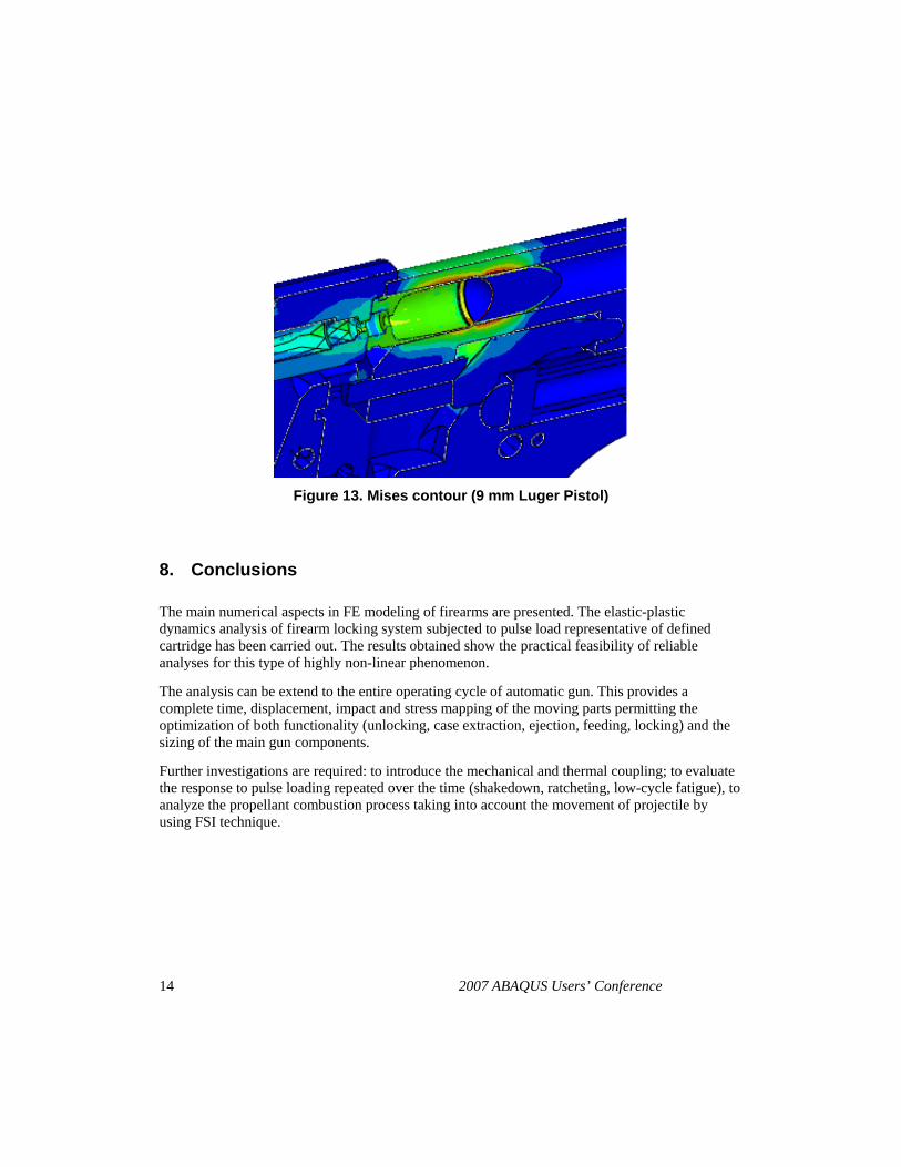
Figure 13. Mises contour (9 mm Luger Pistol)
8. Conclusions
The main numerical aspects in FE modeling of firearms are presented. The elastic-plastic dynamics analysis of firearm locking system subjected to pulse load representative of defined cartridge has been carried out. The results obtained show the practical feasibility of reliable analyses for this type of highly non-linear phenomenon.
The analysis can be extend to the entire operating cycle of automatic gun. This provides a complete time, displacement, impact and stress mapping of the moving parts permitting the optimization of both functionality (unlocking, case extraction, ejection, feeding, locking) and the sizing of the main gun components.
Further investigations are required: to introduce the mechanical and thermal coupling; to evaluate the response to pulse loading repeated over the time (shakedown, ratcheting, low-cycle fatigue), to analyze the propellant combustion process taking into account the movement of projectile by using FSI technique.
14 2007 ABAQUS Users’ Conference

9. References
1. Caratterizzazione Acciaio SAE 8641 allo Stato Normalizzato e Bonificato. Prove di trazione Statica e ad Alta Velocità di Deformazione, private comunication.
2. Cowper, G. R., and P. S. Symonds, “Strain-Hardening and Strain-Rate Effects in The Impact Loading of Cantilever Beams,” Technical report No. 28, Division of Applied Mathematics, Brown University, Providence, RI, September 1957.
3. Johnson, K. L., “Contact Mechanics,” Cambridge University Press, 1995. 4. Jones, N., “Structural Impact,” Cambridge University Press, 1989. 5. Meyers, M. A., “Dynamic Behavior of Materials, John Wiley and Sons, 1994. 6 . Perzyna, P., “Fundamental Problems in Viscoplasticity,” Computer Methods in Applied
Mechanics and Engineering, vol. 41, pp. 251-277, 1983.
2008 Abaqus Users’ Conference 15
Visit the SIMULIA Resource Center for more customer examples.