Embed Size (px)
Citation preview

FC-LOG RS-232 / RS-485 Data LOGGeR USeR ManUaL
FC-LOG-M

Data Logger User Manual FC-LOG-M, 1st Edition 2 Data Logger User Manual FC-LOG-M, 1st Edition 2 I n t e r C o n n e c t i n g A u t o m a t i o n I n c .

Manual HistoryManual Number: FC-LOG-MIssue: 1st EditionIssue Date: 10/16
Publication HistoryIssue Date Description of Changes
1st Edition 10/16 Original
Data Logger User Manual FC-LOG-M, 1st Edition 3I n t e r C o n n e c t i n g A u t o m a t i o n I n c .

Table of Contents Overview of this Publication .........................................................................................5Technical Support ........................................................................................................5Special Symbols............................................................................................................5Introduction .................................................................................................................6Features ........................................................................................................................6What’s in the Box .........................................................................................................7Introduction .................................................................................................................7Specifications ...............................................................................................................8Port and Terminal Block Specifications .......................................................................10Port 1 RS-232 Connections ........................................................................................10Port 2 RS-485 Connections ........................................................................................11USB Port Connections ................................................................................................11Input Power Connections ...........................................................................................11LED Status Indicators / Diagnostic LEDs .....................................................................12Battery Backup ...........................................................................................................13Dimensions ................................................................................................................13Operation ...................................................................................................................14Data Logger File Structure ..........................................................................................15DATA Folder Example .................................................................................................16ERRORS.TXT File Example: Critical Error .....................................................................16Configuring the Data Logger .....................................................................................17Brand/Model - Step 1 Tab ..........................................................................................18Log Options - Step 2 Tab ...........................................................................................21Items to Log - Step 3 Tab ...........................................................................................24Other Buttons ............................................................................................................26Updating Firmware ....................................................................................................27Closing the Configuration Tool ..................................................................................32
Data Logger User Manual FC-LOG-M, 1st Edition 4 I n t e r C o n n e c t i n g A u t o m a t i o n I n c .

Overview of this Publication
Thank you for purchasing the FC-LOG RS-232 / RS-485 Data Logger. This manual shows you how to install and set up your data logger and includes troubleshooting information. For additional information, please refer to the online Help file and instructional video included with the configuration software.
Technical Support
E-mail technical support available at [email protected]
Special Symbols
When you see the “notepad” icon in the left-hand margin, the paragraph to its immediate right will be a special note.
When you see the “exclamation mark” icon in the left-hand margin, the paragraph to its immediate right will be a warning. This information could prevent injury, loss of property, or even death (in extreme cases).
Data Logger User Manual FC-LOG-M, 1st Edition 5I n t e r C o n n e c t i n g A u t o m a t i o n I n c .

Introduction
The FC-LOG data logger is a low-cost, user-configurable, DIN-rail or panel-mount data logger. When connected to a PC through a USB cable, the logger appears on your PC as a mass storage device. When connected to a 24VDC supply or powered by the serial port of a programmable logic controller (PLC), the FC-LOG will log data from the PLC and store the data in standard CSV format onto the included 4GB microSD card. Each item logged is date-time stamped in the CSV file. This file can be retrieved from the logger and then imported to the software of your choosing via a USB port. Because the data is stored on a removable microSD card, you will not lose your data files if power is lost.The FC-LOG currently supports DirectNET protocol for most AutomationDirect DirectLOGIC PLCs. It also supports Modbus RTU protocol for some DirectLOGIC PLCs, all Do-more PLCs, all CLICK PLCs, all P2000/P3000 PLCs and other Modbus RTU devices.
Features
• Removable 4GB microSD card (installed)• Real-time clock with battery backup• Battery included (installed)• Software configurable (software installed on microSD card; accessible when connected to USB port)• Free firmware updates
Data Logger User Manual FC-LOG-M, 1st Edition 6 I n t e r C o n n e c t i n g A u t o m a t i o n I n c .

What’s in the Box
The FC-LOG data logger includes the following:
• Data logger module• RS-232/RJ12 cable• USB cable• Connectors (installed)• 4G microSD card (installed)• Battery (installed)• Quick start insert (not shown in
photo)
The software configuration tool and Help videos are on the microSD card, which is accessible when the data logger is connected to a PC via the USB port.
MicroSD card contents are also available for download from our website at: plclogger.com
Panel or DIN-rail mountableMicro SD Drive and
Battery Location (Remove cover)
Port 1 RS-232 RJ12 Connector
USB Connector
Port 1 Connector
Port 2 RS-485 Connector
Identification
24 VDC Power Connector (Optional)
Data Logger User Manual FC-LOG-M, 1st Edition 7I n t e r C o n n e c t i n g A u t o m a t i o n I n c .

Specifications
General Specifications
Mounting 35mm DIN-rail or panel mount (with no orientation restrictions)
Operating Temperature0 to 60°C (32 to 140°F)IEC 60068-2-14 (Test Nb, Thermal Shock)
Storage Temperature
-20 to 70°C (-4 to 158°F)IEC 60068-2-1 (Test Ab, Cold)IEC 60068-2-2 (Test Bb, Dry Heat)IEC 60068-2-14 (Test Na, Thermal Shock)
Humidity5 to 95% (non-condensing)IEC 60068-2-30 (Test Db, Damp Heat)
Environmental Air No corrosive gases permitted (EN61131-2 pollution degree 1)
VibrationMIL STD 810C 514.2IEC60068-2-6 (Test Fc)
ShockMIL STD 810C 516.2IEC60068-2-27 (Test Ea)
Field-to-Logic-Side Isolation 1800 VAC applied for 1 second (100% tested)Insulation Resistance >10M Ohms @ 500VDC
Noise Immunity
NEMA ICS3-304IEC 61000-4-2 (ESD)Impulse 1000V @ 1 micro-second pulseIEC 61000-4-4 (FTB)RFI, (145 MHz, 440 Mhz 5W @ 15cm)IEC 61000-4-3 (RFI)
Communication Max LengthRS-232: 50 ft (15.24m); RS-485 (single device): 3,280ft (1,000m)
Weight 0.3 lb (136g)USB Isolation Not isolatedAgency Approvals UL (file number E157 382), CE
Terminal Block Specifications
Number of Pins2 (Dinkle: EC350V-02P), 3 (Dinkle: EC350V-03P), 5 (Dinkle: EC350V-05P)
Wire Range28-16 AWG Solid or Stranded Conductor;Wire strip length 5/16 in (6-7 mm)
Screw Driver Size (Slotted) 0.4T x 2.5W mm (AutomationDirect part number TW-SD-VSL-1)
Screw Size M2Screw Torque 1.7 inch-pounds (0.19 Nm)Type Removable
Power Specifications
Input Voltage (Vin) 5VDC via USB port, 24VDC via terminal block, 5VDC via PLC RJ12 port
Input Current at Vin200mA (5VDC - USB), 200mA (24VDC - terminal block), 150mA (5VDC - PLC RJ12)
Protection Type, Component Polarity/surge, polarity protection diode
Data Logger User Manual FC-LOG-M, 1st Edition 8 I n t e r C o n n e c t i n g A u t o m a t i o n I n c .

Serial Communications Ports 1 and 2 SpecificationsCommunication Standards RS-232, RS-485 ( single device)Communication Protocols DirectNET, Modbus RTUSelectable Baud Rates 9600, 19200, 38400, 57600, 115200K
Cable RequiredAutomationDirect part number ZL-RJ12-CBL-2 (included) when using RJ12 connector; DV-1000CBL will also work.
Minimum Sample Rate As fast as PLC responds (130 samples per second at 115.2 kbaud)
Log Data File Type Comma Separated Value - CSV
Compatible PLCsCLICK PLC, DL05, DL06, D2-240, D2-250, D2-250-1, D2-260, D4-430, D4-440, D4-450, P2000, P3000, Do-more, or any Modbus RTU-capable PLC or device
USB Communications Port SpecificationsUSB Mode Mass storage deviceUSB Speed Full speed, USB 2.0 compliantQuiescent Current 1.0mA
User-Configurable Logging ParametersSource of Date On-board real-time clock or PLC Logging Data Trigger Interval (1 second minimum), PLC event, or continuousNumber of Samples Logged per Trigger 1 to 100
Create New Log File Day, week, month, or PLC event
Log File NamesCreates log file names from 0001log.CSV to 9999log.CSV
Battery / Clock SpecificationsBattery Type Coin, lithium (battery included)Battery Voltage Rating 3.0VDCBattery Current Rating 560mAReplacement Part Number CR2354; AutomationDirect part number D2-BAT-1
Battery Life, OperationEstimated 9 years with no power applied. Battery only runs clock when power is not applied. All data is stored on the removable 4G microSD card.
Clock Accuracy± 2 seconds per day @ 25˚C; ±10 seconds per day @ 60˚C
MicroSD Drive SpecificationsMass Storage Memory 4GB (included)Max. Recommended Size 8GBFormat FAT32File Structure 8.3 filename format, 9999 files maximum.
Specifications, continued
Data Logger User Manual FC-LOG-M, 1st Edition 9I n t e r C o n n e c t i n g A u t o m a t i o n I n c .

Port and Terminal Block Specifications
Port 1 RS-232 Connections
6-pin RJ12 FemaleModular Connector
1
6
Terminal Number
Terminal Name Description
1 COM Common2 NC Not used3 RXD RXD; Receive4 TXD TXD; Transmit5 VDC IN +5VDC IN6 COM Common
RS-232 connections can be made via either the plug-in RJ12 connector or the RS-232 terminal block. Only one of these RS-232 ports can be used at any one time for data logging.
RJ12 Port RS-232 Terminal Block
Terminal Number
Terminal Name Signal
1 5Vin +5VDC Input2 TXD Transmit3 RXD Receive4 RTS Request to Send5 COM Common
+ INPUT24VDC±10%
200mA
SD Card
FC-LOGDATA LOGGER
RS-232/485,USB
USB
ISOLATED
1 COM2 NC3 RXD4 TXD5 5VDC IN6 COM
PORT 2RS-485
PORT 1RS-232
USB 2.0COMPLIANT5VDC,250mA
5VinTXDRXDRTS
COMV+
COM
+-
COM
5VTXDRXDRTSCOM
V+COM
+-COM
RS-485
Power24VDC
(Optional)
RS-232
RS-232(RJ12)
USB
Data Logger User Manual FC-LOG-M, 1st Edition 10 I n t e r C o n n e c t i n g A u t o m a t i o n I n c .

Mating face of USBtype B female
1
2
4
3
USB Port Connections
Pin Number Signal
1 +5VDC IN2 -Data3 +Data4 Common
RS-485 Port 2 Terminal Block
Terminal Name Description
+ Transmit– Receive
COM Common
External 24 VDC Power Terminal Block
Terminal Name Description
V+ +24VDC ±10% connection
COM Common
Input Power Connections
The module can be powered in two ways for data logging:Option 1: By connecting a customer-supplied power supply that is rated for 24VDC +/-10% @ 200mA to the
external 24VDC Power Block terminals.Option 2: By the 5VDC pin 5 on the RJ12 port (if 5VDC is provided from the PLC or other device to which it is
connected).For mass data storage, the module is powered by the 5VDC provided by pin 1 of the the USB port.
Input power options 1 or 2 can be used. DO NOT connect power to option 1 and option 2 at the same time. Damage to the unit can result.
Port 2 RS-485 Connections
RS-485 Port 2 connects to a single device only.
A USB cable can be safely connected to this port to switch the data logger to mass storage mode while powered up.
Data Logger User Manual FC-LOG-M, 1st Edition 11I n t e r C o n n e c t i n g A u t o m a t i o n I n c .

LED Status Indicators / Diagnostic LEDs
LED Status Indicators
LED Status Description
Red (Diagnostic 1)
OnDiagnostic indication - see table below
OffGreen
(Diagnostic 2)On
Diagnostic indication - see table belowOff
Green (RX)On RS-232/RS-485 activity: Flashes when activity
occurs on the RS-232/RS485 receive linesOff No signal
Green (TX)On RS-232/RS-485 activity: Flashes when activity
occurs on the RS-232/RS485 transmit linesOff No signal
Yellow (USB) On USB connectedOff USB not connected
Yellow (microSD; see photo for
location)
OnThe yellow LED blinks whenever the SD card is being accessed. It may appear to be on solid
while its connected to a PC.Off No access
Red and Green Diagnostic LEDs
Red LED Green LED Cause Solution
OffFast flashing (250mS on; 250mS off)
Normal operation as a mass storage devce. This means the data
logger is connected to a USB port and has a
usable SD card installed in the drive.
Normal operation - no solution required.
OffSlow flashing (2400mS on; 100mS off)
Normal operation as a Data Logger. This
means the device has a usable SD card installed in the drive and a valid
configuration file.
Normal operation - no solution required.
Flashing(250ms ON, 250ms OFF,250ms ON,750ms OFF)
Flashing(1250ms OFF,250ms ON)
Logger Critical ErrorCheck the ERRORS.TXT file in the root of the
microSD card for error information.
Fast flashing (250mS on; 250mS off)
Off No SD card or unusable SD card in drive.
Insert proper SD card into the holder and make sure it snaps into place.
Fast Flashing(250ms ON,250ms OFF)
Fast Flashing(250ms OFF,250ms ON)
Firmware errorBoot loader senses that firmware image in flash memory is corrupted.
Update firmware.
5V
TXD
RXD
RTS
COM
V+COM
+
-
COM
USB
TX
RX
*microSD
Diag 1
Diag 2
* microSD card is located at the top, center, on LEFT face of module.
microSD LED location
Data Logger User Manual FC-LOG-M, 1st Edition 12 I n t e r C o n n e c t i n g A u t o m a t i o n I n c .

Dimensionsmm [inches]
FC-LOG RS-232 / RS-485
Data Logger
Battery Backup
The back-up battery’s only function is to keep the clock running when the power is off. The FC-LOG data logger does not use the battery when it is powered up. (Data stored on the microSD card will be retained when power is off.) Battery life is estimated to be nine years with no power applied; however, this will vary depending on environmental conditions.If the battery is dead or not installed and you have the logger configured to use the logger clock for the source of the date/time stamp, the date/time of your data will start at 1/1/2012-00.00.00. If you have the logger configured so the date/time source is the PLC it does not matter if the battery is dead or not installed.If you do not set the clock and you set the date/time stamp to use the logger internal clock, the date/time stamp will start at 1/1/2012-00.00.00.
Battery Location (Remove Cover)
Data Logger User Manual FC-LOG-M, 1st Edition 13I n t e r C o n n e c t i n g A u t o m a t i o n I n c .

Operation
The logger module has two modes of operation: USB mode and Logging mode.
USB Mode - Mass Storage Device
If the FC-LOG module is in logger mode, connect the USB port to a PC. The FC-LOG will automatically switch from logger mode to mass storage mode. This is indicated by a fast flashing Green DIAG LED. If the FC-LOG module is not powered up and the USB port is connected to a PC, it will power off the PC’s USB port. It will show up as a mass storage device in the PC, just like a flash drive. The microSD card is in standard FAT32 format.When you are finished copying, moving data files or configuring the data logger, eject the USB device and unplug the USB cable. If the FC-LOG module has external power already connected (24VDC or 5VDC from PLC serial port), the unit will automatically switch to logging mode.For example, if the module is installed in a control panel and is logging data, you can walk up to it and plug in aUSB cable. You can now copy or move data files from the logger. When you are finished, you can unplug the USBcable and the logger will return to logging.
In Mass Storage mode the logger operates like any other removable storage device. You must use the Windows ‘Safely Remove Hardware’ icon on the tool bar to shut down the device before removing it. Failure to do this can damage the device or permanently corrupt or lose your data.
Logging Mode
The FC-LOG module will function as a data logger when a USB cable is not connected, the unit is powered in one of two ways and a valid RS-232 / RS-485 connection is made. It will poll and log the configured data points specified in the software configuration. This is indicated by a slow flashing Green DIAG LED.The FC-LOG needs to be powered by a 24VDC power supply or powered by 5VDC from the serial port of a PLC or field device. While in logging mode, the FC-LOG will log data from the PLC and store the data, in standard CSV format, to the included 4GB microSD card. Each item logged is date-time stamped, as configured in the software. This file can be retrieved off the logger and then imported to the software of your choosing via the USB port or by removing the microSD card. Because the data is stored on the microSD card, you will not lose your data files when power is removed.
Do not connect both the 5VDC from Port 1 and 24VDC from Input power at the same time. This can cause serious damage to the unit.
Data Logger User Manual FC-LOG-M, 1st Edition 14 I n t e r C o n n e c t i n g A u t o m a t i o n I n c .

Data Logger File Structure
When you click on the FC-LOG drive on the right side of the Windows Explorer, the following screen appears.
1. CONFIGS Folder: This folder contains all previously saved XML tool files used in the configuration tool. It also contains a copy of the last configuration of the logger. If the configuration file in the DATA folder gets corrupted or erased, the logger will copy the configuration file from the CONFIGS folder to the DATA folder and run it.
2. DATA Folder: This folder contains the CSV log files created by the logger. For every CSV log file, there will be a corresponding TXT file with information about that log, such as configuration used, communications errors, etc. The DATA folder will also contain the actual configuration file created by the configuration tool, named CONFIG.TXT.
3. FIRMWARE Folder: If you need to upgrade the firmware, download the new firmware file from the www.plclogger.com website and place it into this folder. Instructions for updating the firmware are included later in the manual.
4. HELP Folder: This folder contains the HELP file PDF and help videos on how to setup the logger.5. OLDDATA Folder: When you reconfigure the logger, all the old data files, TXT files and configuration files
in the DATA folder are moved automatically to this folder. These files will be placed in a new folder which is named with the date of the reconfiguration. After doing this, the only items in the DATA folder are the new configuration file and new log files. Any older data files in the OLDDATA folder will remain there as new files are added.
6. SYSTEM Folder: This folder contains system files necessary to run the configuration tool and other files necessary for the logger. Please do not move or modify these files or the logger will not run properly.
7. ERRORS.TXT file: If any critical errors take place, the ERRORS.TXT file is created. If it already exists, information on new critical errors is appended to it. If there are no critical errors, the ERRORS.TXT file will not exist.
8. TLV.BIN file: This file is used by the FC-LOG. Do not open, modify or remove from this location. 9. TOOL File: This is the configuration tool used to configure the logger. This process is explained in more detail
later in the manual. The configuration tool is self-contained and does not install any software on your PC. It does require Visual Basic.NET (VB.NET) version 2.0 or later. When you double-click on the icon, the PC will notify if the correct VB.NET version is not installed.
2
3
4
5
6
7
8
1
9
Data Logger User Manual FC-LOG-M, 1st Edition 15I n t e r C o n n e c t i n g A u t o m a t i o n I n c .

DATA Folder Example
The first 0001LOG file is the CSV file with the logged data. The second 0001LOG file is the TXT file that con-tains information about the CSV file. The CONFIG.TXT file contains a copy of the last logger configuration. The SEQUENCE.TXT file is used by the data logger to keep track of which log file number it is currently at.
ERRORS.TXT File Example: Critical Error
If the logger experiences a critical error that stops it from logging, a file named ERRORS.TXT is created if one does not already exist. If the ERRORS.TXT file already exists, the information of the new error is appended to the file. It contains information about the critical error. For example, if we configure the logger to communicate with a DL05 and instead the logger is connected to a DL250-1, the following will occur:
• The logger will stop logging.• The red and green diagnostic LEDs will start flashing. • An ERRORS.TXT file will be created if one does not already exist or error information will be appended to the
existing ERRORS.TXT file. If this occurs, open the file to see what the errors are. Remember, if you have no critical errors, the ERROR file will not be present.
ERRORS.TXT file
Data Logger User Manual FC-LOG-M, 1st Edition 16 I n t e r C o n n e c t i n g A u t o m a t i o n I n c .

Configuring the Data Logger
This section provides step-by-step instructions for configuring the FC-LOG data logger. These instructions assume the data logger is connected to your PC via a USB cable, and you have the data logger files on the screen as illustrated below.
To configure the logger, follow these general steps:1. To open the configuration tool, double-click on the TOOL icon as shown above. The FC-LOG Tool window opens.2. In the figure below, notice the three tabs along the top: a. Brand/Model – STEP 1 b. Log Options – STEP 2 c. Items to Log – STEP 33. Complete the fields on each tab using the information for each tab on the following pages.
Double-click on this to open the configuration tool.
Data Logger User Manual FC-LOG-M, 1st Edition 17I n t e r C o n n e c t i n g A u t o m a t i o n I n c .

NOTE: Changing the Brand selection will reset all form fields
1. Brand: Use this dropdown menu to select which brand PLC or device you want to log data from. The FC-LOG supports the following brands: CLICK PLC, DirectLOGIC PLC, Do-more PLC, and Modbus RTU devices.
2. Model: When a PLC is selected for the Brand item, the Model field becomes available and the PLC model needs to be selected.
NOTE: Changing the Model selection will reset all form fields.
a. For the CLICK PLC family, the logger will communicate with all CLICK PLC CPUs using the Modbus RTU protocol. You will set this up in the CLICK PLC programming software. In the HELP Folder there is a help video with step-by-step instructions on how to set this up in the logger and the PLC programming software.
Brand/Model – STEP 1 Tab:
1
2
3
4
5
6
7
8
Data Logger User Manual FC-LOG-M, 1st Edition 18 I n t e r C o n n e c t i n g A u t o m a t i o n I n c .
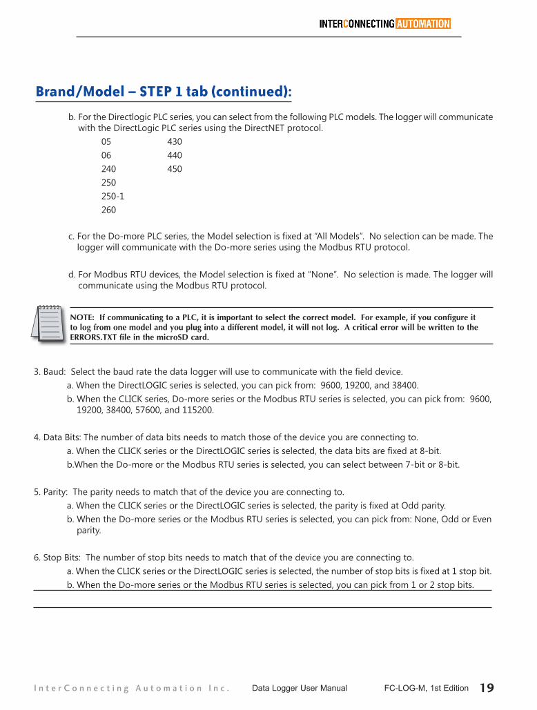
b. For the Directlogic PLC series, you can select from the following PLC models. The logger will communicate with the DirectLogic PLC series using the DirectNET protocol.
05 430 06 440 240 450 250 250-1 260
Brand/Model – STEP 1 tab (continued):
c. For the Do-more PLC series, the Model selection is fixed at “All Models”. No selection can be made. The logger will communicate with the Do-more series using the Modbus RTU protocol.
d. For Modbus RTU devices, the Model selection is fixed at “None”. No selection is made. The logger will communicate using the Modbus RTU protocol.
NOTE: If communicating to a PLC, it is important to select the correct model. For example, if you configure it to log from one model and you plug into a different model, it will not log. A critical error will be written to the ERRORS.TXT file in the microSD card.
3. Baud: Select the baud rate the data logger will use to communicate with the field device. a. When the DirectLOGIC series is selected, you can pick from: 9600, 19200, and 38400. b. When the CLICK series, Do-more series or the Modbus RTU series is selected, you can pick from: 9600,
19200, 38400, 57600, and 115200.
4. Data Bits: The number of data bits needs to match those of the device you are connecting to. a. When the CLICK series or the DirectLOGIC series is selected, the data bits are fixed at 8-bit. b.When the Do-more or the Modbus RTU series is selected, you can select between 7-bit or 8-bit.
5. Parity: The parity needs to match that of the device you are connecting to. a. When the CLICK series or the DirectLOGIC series is selected, the parity is fixed at Odd parity. b. When the Do-more series or the Modbus RTU series is selected, you can pick from: None, Odd or Even
parity.
6. Stop Bits: The number of stop bits needs to match that of the device you are connecting to. a. When the CLICK series or the DirectLOGIC series is selected, the number of stop bits is fixed at 1 stop bit. b. When the Do-more series or the Modbus RTU series is selected, you can pick from 1 or 2 stop bits.
Data Logger User Manual FC-LOG-M, 1st Edition 19I n t e r C o n n e c t i n g A u t o m a t i o n I n c .

7. Clear All: This will clear all form fields. You get the following warning:
8. The right hand side of the Brand/Model – STEP 1 tab, displays the port settings needed in the field device to match the settings configured in the logger. For example, if you change the baud rate on item 3, the baud rate is updated on the right hand side of the tab.
9. Swap Byte: When the Modbus RTU series is selected, the “Swap Byte” becomes available. You can select Yes or No. You will need to find out from the supplier of the field device if a byte swap is necessary to read the data correctly.
10. Swap Word: When the Modbus RTU series is selected, the “Swap Word” becomes available. You can select Yes or No. You will need to find out from the supplier of the field device if a word swap is necessary to read the data correctly.
9
10
Data Logger User Manual FC-LOG-M, 1st Edition 20 I n t e r C o n n e c t i n g A u t o m a t i o n I n c .

1. Log Trigger: The logger can be triggered to log data in three ways: a. Continuous: The logger continuously polls the field device for the items to log as fast as possible. b. Event based: The logger monitors the status of an element in the field device, as fast as possible.
Logging of data is triggered when the field device element meets the configured condition. c. Interval: The logger will log data items based on the interval time. For example, if you set the interval
time to 10 seconds, once powered up, it will trigger the log of all data items to log every 10 seconds.
2. Event based trigger configuration: Configure the element and conditions used to trigger logging. a. Element: PLC or Modbus RTU device element i. When the CLICK series is used, you can select from the following addressing elements: X, Y, C, T
or CT ii. When the DirectLOGIC series is used, you can select from the following addressing elements: X,
Y, C, T or CT iii. When the Do-more series is used, you can select from the following addressing elements: MC
or MI iv. When the Modbus RTU series is used, you can select from the following addressing elements:
Read coil status (Code 1) or Read input status (Code 2)
b. Address: Enter the address associated with the selected element. When the Address field is selected, the allowed addressing range is displayed in blue letters. Make sure the address entered is within the range allowed by the PLC or Modbus RTU device being used.
Log Options – STEP 2 Tab
2
3
45
6
7
81
9
Data Logger User Manual FC-LOG-M, 1st Edition 21I n t e r C o n n e c t i n g A u t o m a t i o n I n c .

c. Trigger Type: Select the state of the element that you want to trigger the logging of data. The options are:
i. Log continuous when ON ii. Log continuous when OFF iii. Once on transition to high iv. Once on transition to low v. Once on transition to either high or low
3. Interval time: Enter the time used to trigger the logging of data. Using the format HH:MM:SS, you can enter time in the range of 1 second to 23:59:59 (23 hours, 59 minutes and 59 seconds).
4. COM Port: The serial connection to the PLC or Modbus RTU device can be RS-232 or RS-485. NOTE: The RS-485 connection is to a single device.
5. Samples per trigger: Select how many times the data is logged from the “Items to Log” tab, each time the logger is triggered. For example, if this is set to 10, every time the logger is triggered, it will log all the items listed in the “Items to Log” tab 10 times. The allowed range is 1 to 100.
6. New File Trigger: Select what causes (if anything) the logger to create a new log file in the DATA folder. a. You can select from: None, Event, Day, Week or Month. b. If, for example, you select Day, Week or Month, a new log file is created in the DATA folder at midnight
on that trigger. c. If you select Event, you will need to select what addressing element triggers the new file creation. This
addressing element is checked every 10 seconds. Make sure the addressing element is kept ON long enough by the PLC/field device so the logger can see it.
i. From the Element drop down, you can select the address element you want to use as the trigger. It will list the available elements for the PLC/Field device used.
ii. Enter the address of the element in the field to the right of the element drop down. The address range for the element will be displayed in blue letters towards the bottom of the tab.
d. If you select None, a new file will be created only when the number of rows in the CSV file exceed the user setting in the Rows in CSV field.
e. The logger will create a new CSV log file and corresponding TXT file in the DATA folder: i. Every time you power it up. ii. When the present file receiving the data reaches the value specified in the Rows in CSV field
under the Log Options tab. iii. Every time the Event, specified in New File Trigger section, takes place.
f. When the logger creates a new file, it appends a number to the beginning of the file, i.e. 0001, 0002, 0003, etc. This is very similar to what digital cameras do today. It will continue to create files from 0001log.CSV to 9999log.CSV. After reaching 9999log.CSV, it will start over at 0001log.CSV, appending new data to the existing file. It does not overwrite or delete existing files. All CSV log files are found in the DATA folder.
Data Logger User Manual FC-LOG-M, 1st Edition 22 I n t e r C o n n e c t i n g A u t o m a t i o n I n c .

7. Rows in CSV: Set this to the number of rows you want in the CSV log file.
Note: Windows Excel 2003 and earlier supported 65535 rows, so if you are going to import the data file to Excel 2003 or earlier, make sure you do not exceed this. We suggest that you set it at 64000 to allow some room on the import. Excel versions later than 2003 support 1,048,576 rows. If you set this field to more than your Excel program can import, you will not be able to import your data to Excel without going into the CSV file and reducing the num-ber of rows manually. Two of the rows are automatically used for the header on the columns in the CSV. Therefore, if you want 5000 rows of data set the rows to 5002. The logger automatically uses two of the total rows you allot for the header column text.
8. Source of Date-Time Stamp: Select from Logger, PLC or User Defined. a. Logger: When selected, the internal clock of the logger will be used to stamp the date-time of each line
of data logged to the CSV log file. (Use the Set Logger Clock to update the internal clock) i. When the Do-more series or the Modbus RTU series is used, the logger selection field is fixed at
Logger. PLC or User defined are not available.
b. PLC: The logger retrieves the date and time from the PLC and uses it to stamp the date-time of each line of data logged to the CSV log file.
i. PLC as the source of date and time for logging will be available if the PLC/field device used supports a real time clock. For example, if you use a CLICK C0-00DR-D, the PLC selection will not be available because this CPU does not support a real time clock.
ii. The logger is automatically synchronized with the PLC date and time: 1. On power up 2. Once every hour after power up 3. If the PLC date and time is changed while the PLC and logger are both running, the data
in the CSV file will not show the new date and time until it synchronizes again or when the logger power is cycled.
iii. PLC addressing element selection: 1. When a CLICK series PLC that supports the real time clock is used, the real time clock SD
addresses are filled in. 2. When the DirectLOGIC series is used, the real time clock V memory addresses are filled
in.
c. User Defined: Specify the memory locations in the PLC which hold the date and time. i. When the CLICK series is used, enter the DS address for each date and time field. ii. When the DirectLOGIC series is used, enter the V memory address for each date and time field.
9. Set Logger Clock: Select to set the logger internal clock. These values are used when the source of the Date and Time stamp for the data is configured to originate from the logger internal clock.
Data Logger User Manual FC-LOG-M, 1st Edition 23I n t e r C o n n e c t i n g A u t o m a t i o n I n c .

When the CLICK PLC series is used, you do not need to specify the data type because the data type in a CLICK PLC is specific to the memory type. You do need to specify the memory type, the address of the memory type and the column header text.When the DirectLOGIC series, Do-more series or Modbus RTU series is used, you need to specify the memory type, address of the memory type, data type and column header text.
1. Memory type: a. When the Click series is used, select from one of the following memory types: X, Y, C, T, CT, SC, DS, TD,
DD, CTD, DF, DH, or SD.
b. When the DirectLOGIC series is used, select from one of the following memory types: X, Y, C, T, CT, S, or V.
c. When the Do-more series is used, select from one of the following memory types: MC, MI, MIR, or MHR.
d. When the Modbus RTU series is used, select from one of the following memory types: i. Read Coil Status (Code 1) ii. Read Input Status (Code 2) iii. Read Input Register (Code 4) iv. Read Holding Register (Code 3)
2. Address: Indicate the specific address in the PLC/Modbus RTU device where the data resides. (The address range for the memory type is displayed in blue letters towards the bottom of the tab).
When Modbus RTU is selected, you need to know what Modbus addresses you would like to log and what format they are stored in. Also, verify the addressing entered. The module does not do any error checking of the addresses entered in the Items to Log tab.
Items to Log – Step 3 Tab
2 3 4 5
6
1
Data Logger User Manual FC-LOG-M, 1st Edition 24 I n t e r C o n n e c t i n g A u t o m a t i o n I n c .

3. Data Type: (This field is not available when a the Click series is used)
a. Select Discrete when a discrete memory type is used: i. DirectLOGIC memory types: X, Y, C, T, CT, or S ii. Do-more memory types: MC or MI iii. Modbus RTU memory types: Read Coil Status (Code 1) or Read Input Status (Code 2)
b. Select a numeric data type when a memory type that holds a numeric value is used. i. The memory types associated with numeric values are: 1. DirectLOGIC memory types: V 2. Do-more numeric memory types: MIR or MHR 3. Modbus RTU memory types: a. Read Input Register (Code 4) b. Read Holding Register (Code 3)
ii. The available data types for numeric values are: 1. BCD16 2. BCD32 3. UNSIGNED_INTEGER16 4. UNSIGNED_INTEGER32 5. SIGNED_INTEGER16 6. SIGNED_INTEGER32 7. REAL
4. Text Header: Specify the text that goes on the top of the column in the CSV log file for this data point.
5. A Delete Button is displayed when a log item is added to the list.
6. Configure Logger: Click on this button once the logger configuration is complete. The tool will ask you to save your configuration on your computer. After the configuration is saved, the software will take any data in the DATA folder on the logger microSD card and move it to the OLDDATA folder on the root of the logger microSD card. It will place the new CONFIG.TXT file in the DATA folder. It will use this file to configure itself on power up.
The CONFIG.TXT file contains all the items configured by the tool. DO NOT MANIPULATE this file in any way.
Data Logger User Manual FC-LOG-M, 1st Edition 25I n t e r C o n n e c t i n g A u t o m a t i o n I n c .

Other Buttons:
1. Save Settings: Allows you to save the current configuration to your PC’s hard drive for future recall/modification.
2. Load Settings: Allows you to load a previously saved configuration.
3. Help: Opens the Help PDF file.
4. Help Videos: Opens a media viewer. Select the Select Video to View button to access a list of available Help videos. These videos are in the HELP folder on the microSD card.
5. Eject Instructions: When selected, a pop up window comes up with instructions on how to properly eject a USB device from the PC before unplugging it. This helps limit the possibility of corrupting the files in the logger microSD card.
21 3 4 5
Data Logger User Manual FC-LOG-M, 1st Edition 26 I n t e r C o n n e c t i n g A u t o m a t i o n I n c .

Updating Firmware You can easily update the firmware on your FC-LOG data logger from the www.plclogger.com web site.
1. Connect your FC-LOG to your computer with the supplied USB Type A to USB Type B cable. When Windows recognizes the Micro SD card, it will appear in Windows Explorer.
2. To update the firmware, go to www.plclogger.com.3. Click on the Firmware link.4. Scroll down to Firmware Updates.
FIRMWARE Folder
microSD Card
Data Logger User Manual FC-LOG-M, 1st Edition 27I n t e r C o n n e c t i n g A u t o m a t i o n I n c .

6. When the download is complete, open Windows Explorer and go to your Downloads folder to retrieve the firmware .zip archive.
7. Double-click the file that you just downloaded.
Data Logger User Manual FC-LOG-M, 1st Edition 28 I n t e r C o n n e c t i n g A u t o m a t i o n I n c .

8. Expand the zipped file as illustrated below.
9. Select all of the files in the .zip archive, right click and select Copy.
Data Logger User Manual FC-LOG-M, 1st Edition 29I n t e r C o n n e c t i n g A u t o m a t i o n I n c .

10. Right-click on the FC-LOG device and select Paste.
Windows will ask if you want to replace the files on the CD-LOG device.
11. Click Replace the files in the destination.
Right-click on FC-LOG and paste
Data Logger User Manual FC-LOG-M, 1st Edition 30 I n t e r C o n n e c t i n g A u t o m a t i o n I n c .

12. Eject the USB device and unplug the USB cable from the computer.
13. Cycle power on the FC-LOG device to complete the firmware update process.
The following page appears. When it disappears from the screen, your FC-LOG device will be updated.
Data Logger User Manual FC-LOG-M, 1st Edition 31I n t e r C o n n e c t i n g A u t o m a t i o n I n c .

Closing the Configuration Tool
To close the configuration tool, press the X on the top right of the Tool window. You will get the following pop up.
When the OK button is pressed, the tool will close and it will attempt to automatically EJECT the USB device. If this does not work, you will need to do this manually.
Data Logger User Manual FC-LOG-M, 1st Edition 32 I n t e r C o n n e c t i n g A u t o m a t i o n I n c .
![met LOG - lambrecht.net€¢ data management includes wind speed, wind directi on, air humidity, ... 17.8 x 89 x 60 mm ... [LOG] Data logger incl. SD card 00.95800.010000 0,5](https://img.dokumen.tips/doc/110x75/5ad387177f8b9a665f8dce95/met-log-data-management-includes-wind-speed-wind-directi-on-air-humidity.jpg)


![Ser[LOG] DATA LOGGER - lambrecht.net](https://img.dokumen.tips/doc/110x75/61cb56d85bd0b832c813b986/serlog-data-logger-.jpg)
