Embed Size (px)
DESCRIPTION
FBGS - Strain Gauge Technology
Citation preview

Strain Gauge Technology
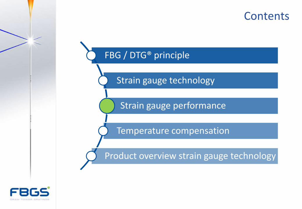
Contents
FBG / DTG® principle
Strain gauge technology
Strain gauge performance
Temperature compensation
Product overview strain gauge technology
Contents
FBG / DTG® principle
Strain gauge technology
Strain gauge performance
Temperature compensation
Product overview strain gauge technology
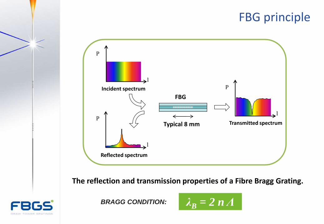
FBG principle
λB = 2 n Λ BRAGG CONDITION:
l
P
Typical 8 mm
FBG
Incident spectrum
Reflected spectrum
Transmitted spectrum
l
P l
P
The reflection and transmission properties of a Fibre Bragg Grating.

FBG principle
l
P ''2' nBragg
l
P n
Bragg2 L
L'
Strained FBG
Unstrained FBG
Strain sensing principle of an FBG
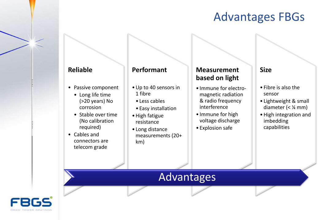
Advantages FBGs
Reliable
• Passive component
• Long life time (>20 years) No corrosion
• Stable over time (No calibration required)
• Cables and connectors are telecom grade
Performant
•Up to 40 sensors in 1 fibre
• Less cables
•Easy installation
•High fatigue resistance
• Long distance measurements (20+ km)
Measurement based on light
• Immune for electro-magnetic radiation & radio frequency interference
• Immune for high voltage discharge
•Explosion safe
Size
• Fibre is also the sensor
• Lightweight & small diameter (< ¼ mm)
•High integration and imbedding capabilities
Advantages
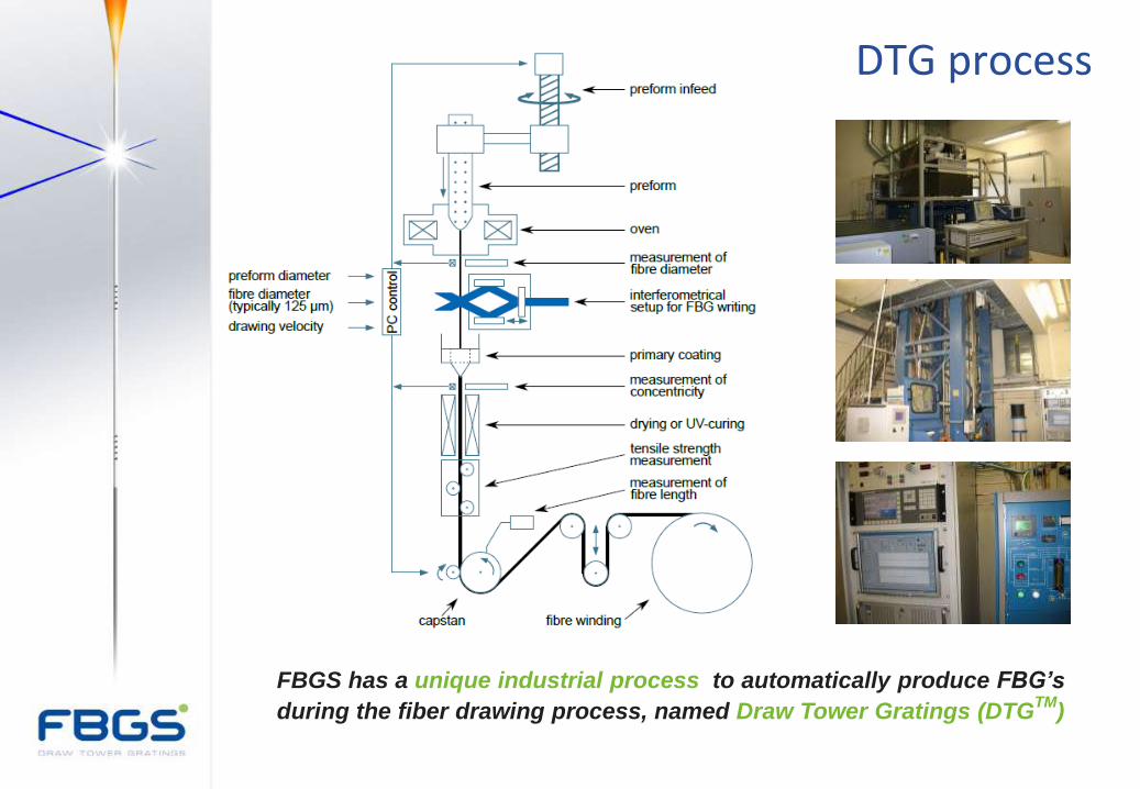
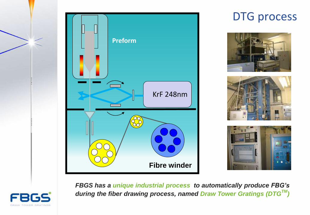
DTG process
FBGS has a unique industrial process to automatically produce FBG’s
during the fiber drawing process, named Draw Tower Gratings (DTGTM
)
DTG process
FBGS has a unique industrial process to automatically produce FBG’s
during the fiber drawing process, named Draw Tower Gratings (DTGTM
)
Preform
Fibre winder
KrF 248nm
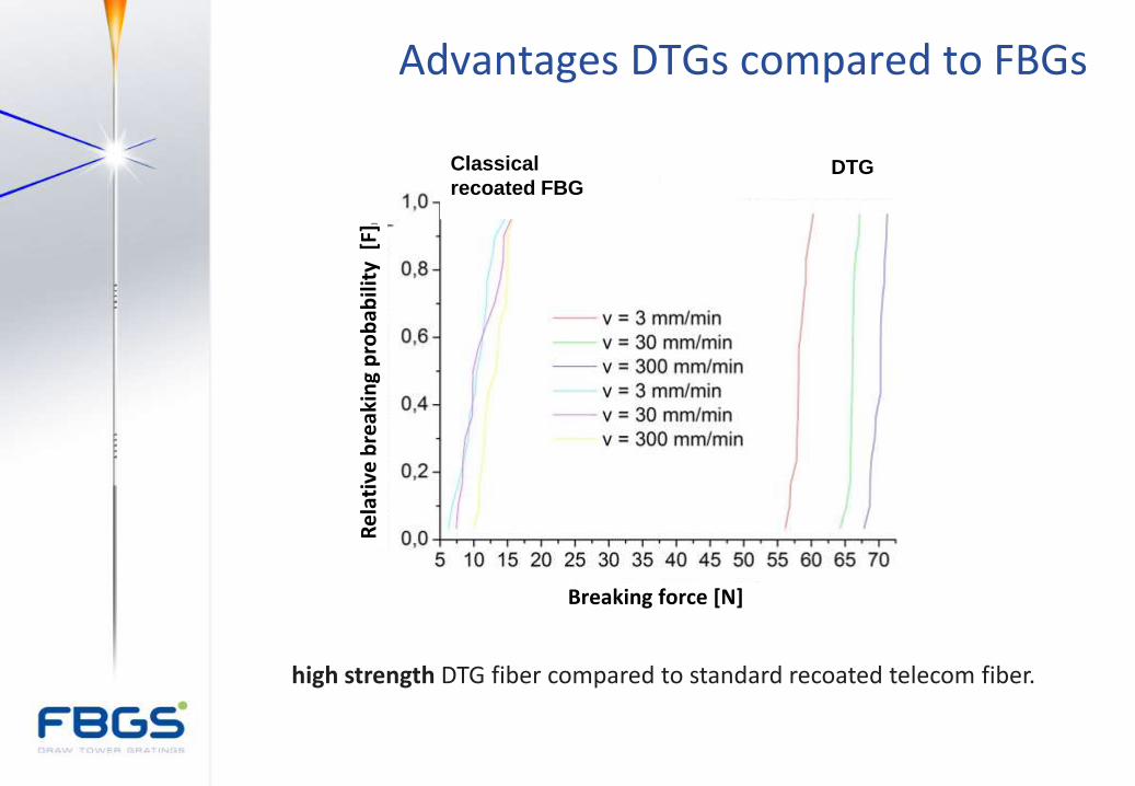
Advantages DTGs compared to FBGs
high strength DTG fiber compared to standard recoated telecom fiber.
Classical
recoated FBG
DTG
Re
lati
ve b
reak
ing
pro
bab
ility
[F]
]
Breaking force [N]
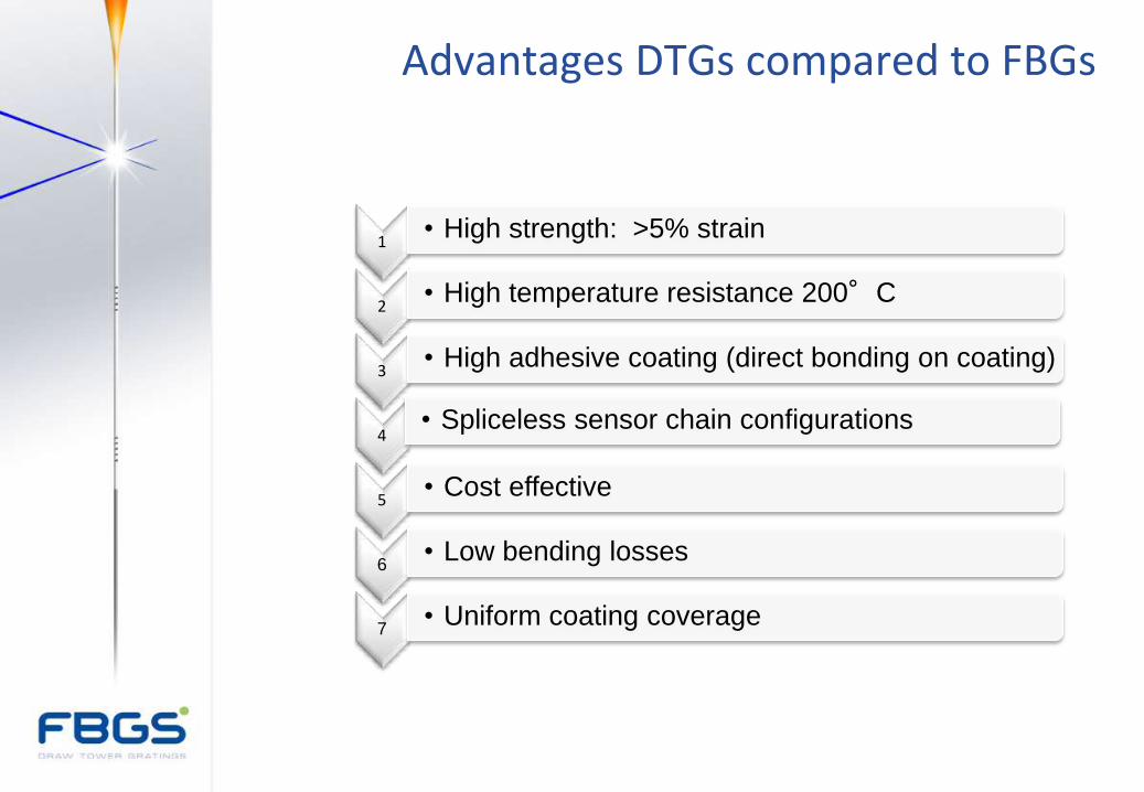
Advantages DTGs compared to FBGs
1 • High strength: >5% strain
2 • High temperature resistance 200°C
3 • High adhesive coating (direct bonding on coating)
4 • Spliceless sensor chain configurations
5 • Cost effective
6 • Low bending losses
7 • Uniform coating coverage
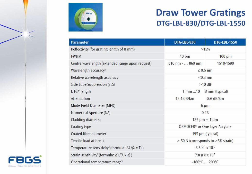
Draw Tower Gratings DTG-LBL-830/DTG-LBL-1550
Contents
FBG / DTG® principle
Strain gauge technology
Strain gauge performance
Temperature compensation
Product overview strain gauge technology
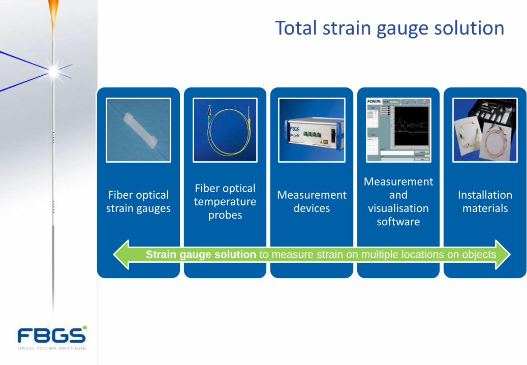
Total strain gauge solution
Fiber optical strain gauges
Fiber optical temperature
probes
Measurement devices
Measurement and
visualisation software
Installation materials
Strain gauge solution to measure strain on multiple locations on objects
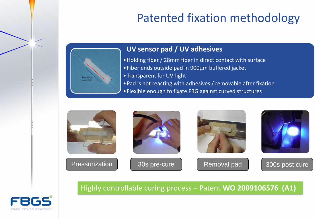
UV sensor pad / UV adhesives
•Holding fiber / 28mm fiber in direct contact with surface
•Fiber ends outside pad in 900µm buffered jacket
•Transparent for UV-light
•Pad is not reacting with adhesives / removable after fixation
•Flexible enough to fixate FBG against curved structures
Pressurization 30s pre-cure Removal pad 300s post cure
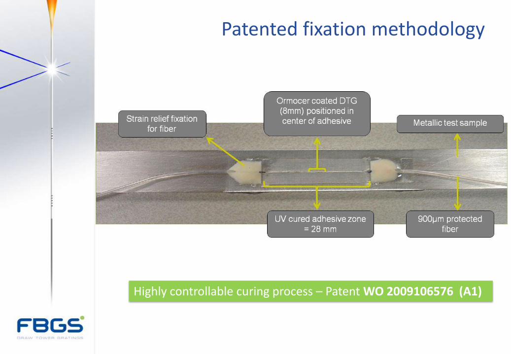
Patented fixation methodology
Highly controllable curing process – Patent WO 2009106576 (A1)
Highly controllable curing process – Patent WO 2009106576 (A1)
Patented fixation methodology
THANK YOU!
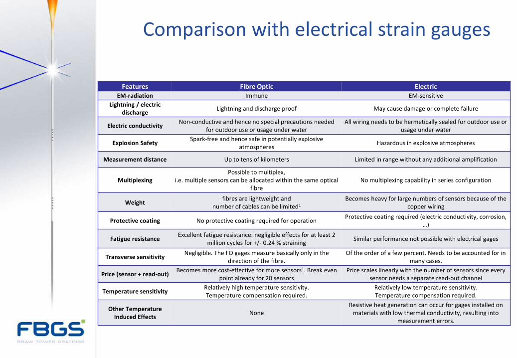
Features Fibre Optic Electric EM-radiation Immune EM-sensitive
Lightning / electric discharge
Lightning and discharge proof May cause damage or complete failure
Electric conductivity Non-conductive and hence no special precautions needed
for outdoor use or usage under water All wiring needs to be hermetically sealed for outdoor use or
usage under water
Explosion Safety Spark-free and hence safe in potentially explosive
atmospheres Hazardous in explosive atmospheres
Measurement distance Up to tens of kilometers Limited in range without any additional amplification
Multiplexing Possible to multiplex,
i.e. multiple sensors can be allocated within the same optical fibre
No multiplexing capability in series configuration
Weight fibres are lightweight and
number of cables can be limited1 Becomes heavy for large numbers of sensors because of the
copper wiring
Protective coating No protective coating required for operation Protective coating required (electric conductivity, corrosion,
…)
Fatigue resistance Excellent fatigue resistance: negligible effects for at least 2
million cycles for +/- 0.24 % straining Similar performance not possible with electrical gages
Transverse sensitivity Negligible. The FO gages measure basically only in the
direction of the fibre. Of the order of a few percent. Needs to be accounted for in
many cases.
Price (sensor + read-out) Becomes more cost-effective for more sensors1. Break even
point already for 20 sensors Price scales linearly with the number of sensors since every
sensor needs a separate read-out channel
Temperature sensitivity Relatively high temperature sensitivity. Temperature compensation required.
Relatively low temperature sensitivity. Temperature compensation required.
Other Temperature Induced Effects
None Resistive heat generation can occur for gages installed on
materials with low thermal conductivity, resulting into measurement errors.
Comparison with electrical strain gauges
Contents
FBG / DTG® principle
Strain gauge technology
Strain gauge performance
Temperature compensation
Product overview strain gauge technology
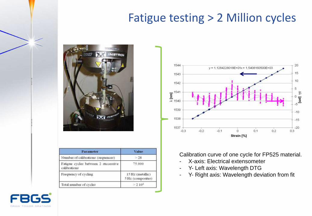
Calibration curve of one cycle for FP525 material.
- X-axis: Electrical extensometer
- Y- Left axis: Wavelength DTG
- Y- Right axis: Wavelength deviation from fit
Fatigue testing > 2 Million cycles
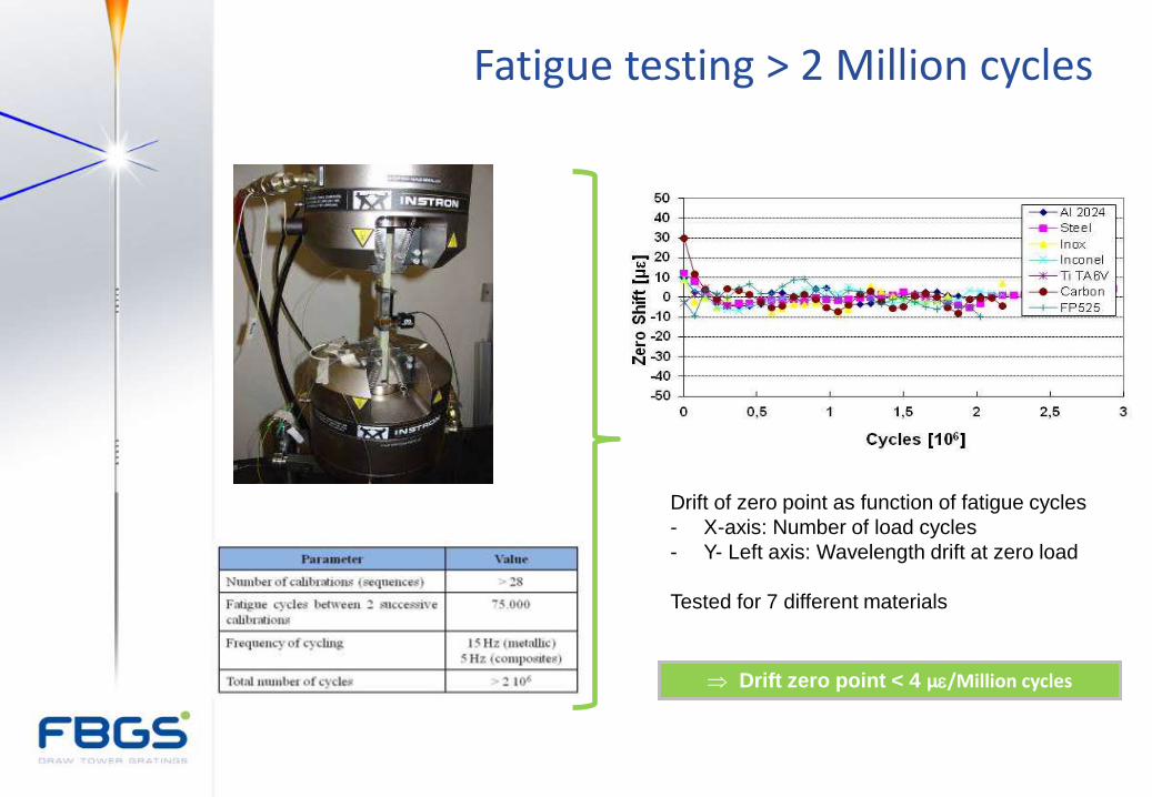
Drift of zero point as function of fatigue cycles
- X-axis: Number of load cycles
- Y- Left axis: Wavelength drift at zero load
Tested for 7 different materials
Drift zero point < 4 µe/Million cycles
Fatigue testing > 2 Million cycles
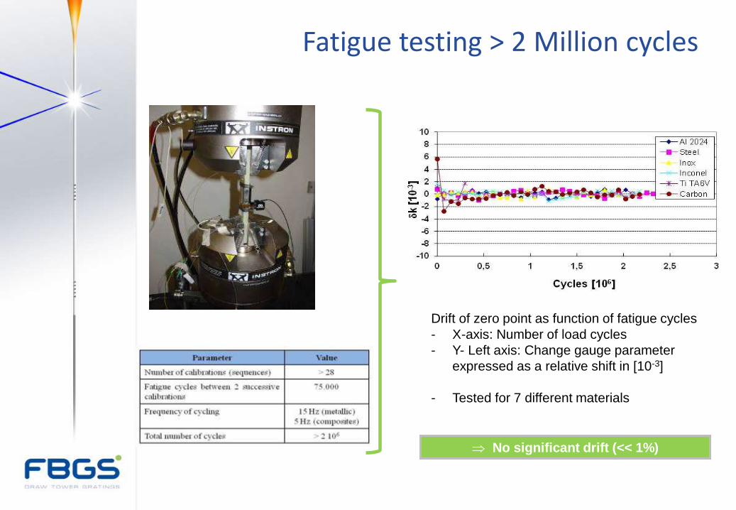
Drift of zero point as function of fatigue cycles
- X-axis: Number of load cycles
- Y- Left axis: Change gauge parameter
expressed as a relative shift in [10-3]
- Tested for 7 different materials
No significant drift (<< 1%)
Fatigue testing > 2 Million cycles
-60
-40
-20
0
20
40
60
80
100
0 10 20 30 40 50 60 70
t [h]
T [
°C]
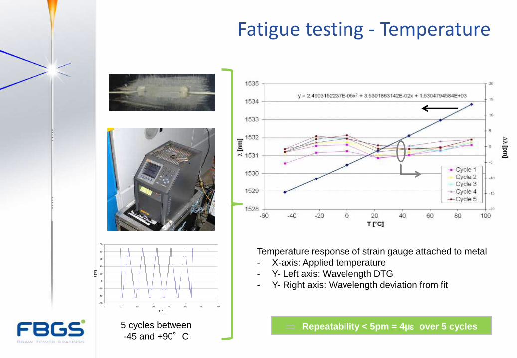
5 cycles between
-45 and +90°C
Temperature response of strain gauge attached to metal
- X-axis: Applied temperature
- Y- Left axis: Wavelength DTG
- Y- Right axis: Wavelength deviation from fit
Repeatability < 5pm = 4µe over 5 cycles
Fatigue testing - Temperature
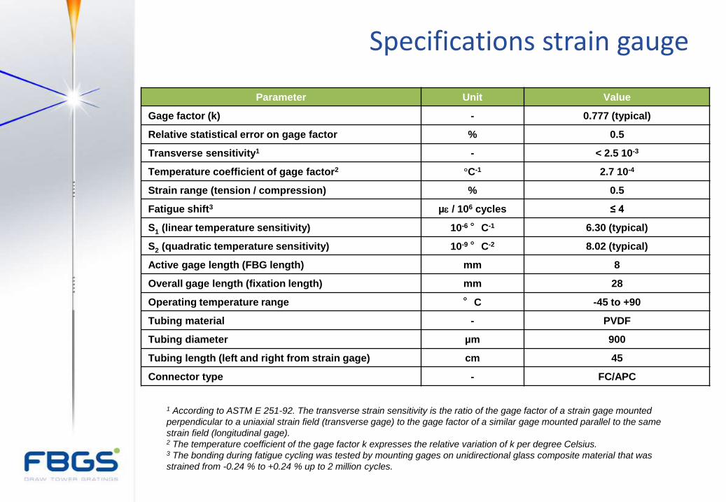
Parameter Unit Value
Gage factor (k) - 0.777 (typical)
Relative statistical error on gage factor % 0.5
Transverse sensitivity1 - < 2.5 10-3
Temperature coefficient of gage factor2 °C-1 2.7 10-4
Strain range (tension / compression) % 0.5
Fatigue shift3 µe / 106 cycles ≤ 4
S1 (linear temperature sensitivity) 10-6 °C-1 6.30 (typical)
S2 (quadratic temperature sensitivity) 10-9 °C-2 8.02 (typical)
Active gage length (FBG length) mm 8
Overall gage length (fixation length) mm 28
Operating temperature range °C -45 to +90
Tubing material - PVDF
Tubing diameter µm 900
Tubing length (left and right from strain gage) cm 45
Connector type - FC/APC
1 According to ASTM E 251-92. The transverse strain sensitivity is the ratio of the gage factor of a strain gage mounted
perpendicular to a uniaxial strain field (transverse gage) to the gage factor of a similar gage mounted parallel to the same
strain field (longitudinal gage). 2 The temperature coefficient of the gage factor k expresses the relative variation of k per degree Celsius. 3 The bonding during fatigue cycling was tested by mounting gages on unidirectional glass composite material that was
strained from -0.24 % to +0.24 % up to 2 million cycles.
Specifications strain gauge
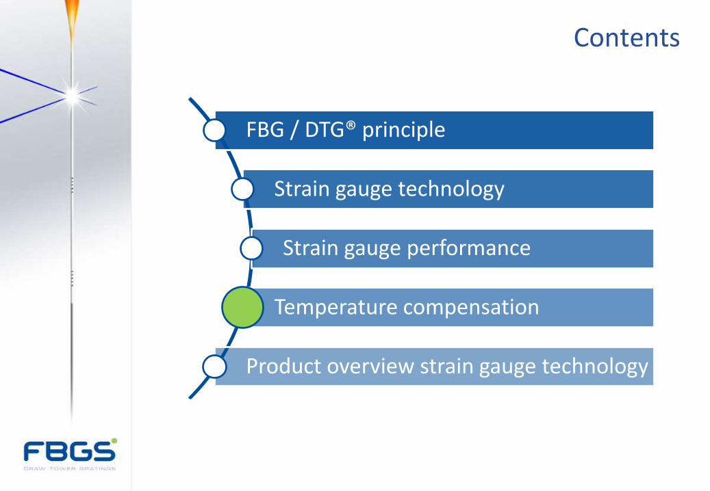
Contents
FBG / DTG® principle
Strain gauge technology
Strain gauge performance
Temperature compensation
Product overview strain gauge technology
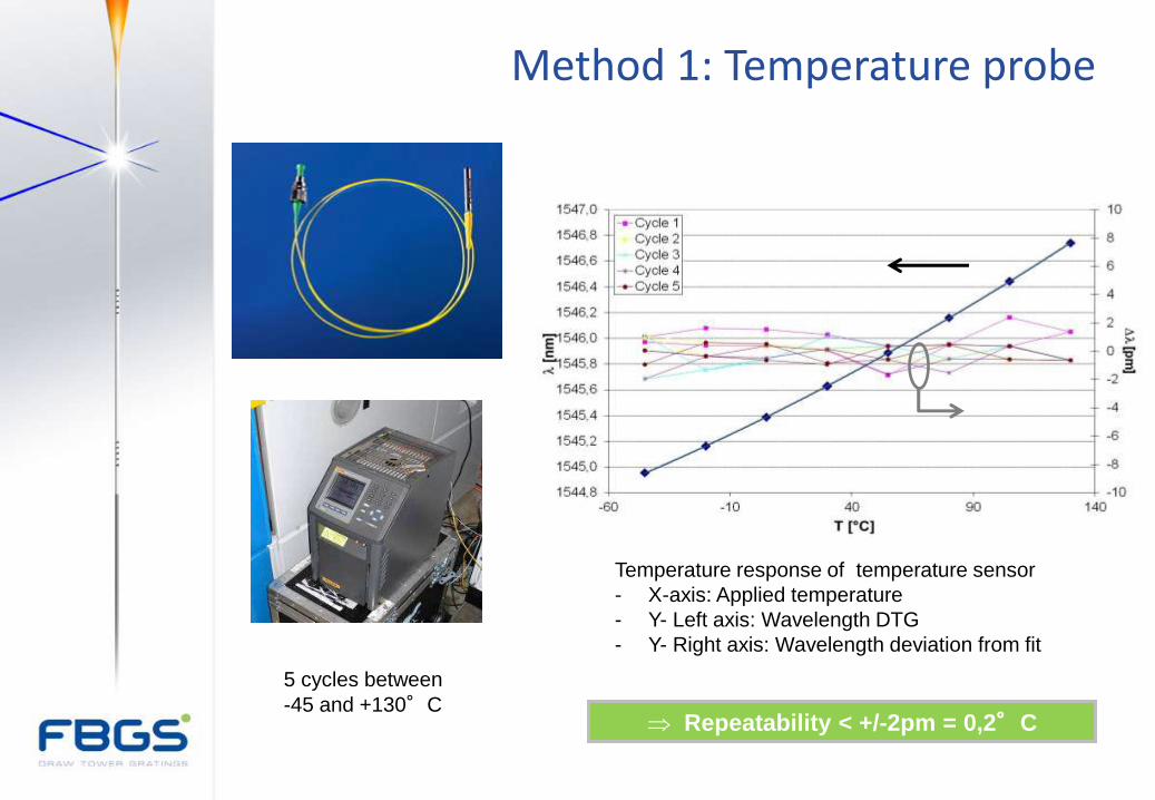
5 cycles between
-45 and +130°C
Temperature response of temperature sensor
- X-axis: Applied temperature
- Y- Left axis: Wavelength DTG
- Y- Right axis: Wavelength deviation from fit
Repeatability < +/-2pm = 0,2°C
Method 1: Temperature probe
'
0
'
0
, lnln1
e
ksmech
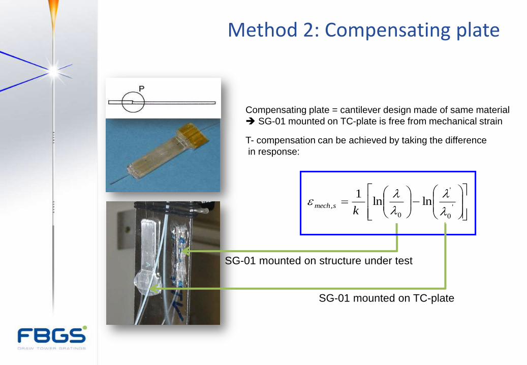
SG-01 mounted on structure under test
SG-01 mounted on TC-plate
Compensating plate = cantilever design made of same material
SG-01 mounted on TC-plate is free from mechanical strain
T- compensation can be achieved by taking the difference
in response:
Method 2: Compensating plate
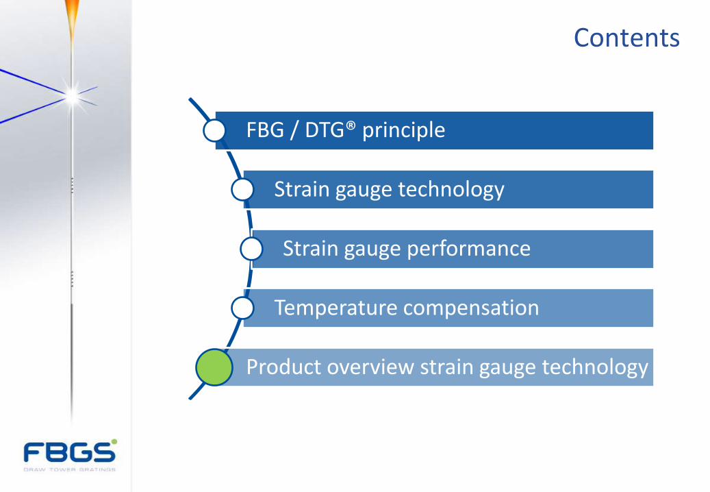
Contents
FBG / DTG® principle
Strain gauge technology
Strain gauge performance
Temperature compensation
Product overview strain gauge technology
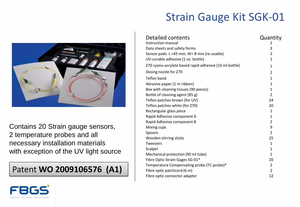
Detailed contents Quantity Instruction manual 1
Data sheets and safety forms 3
Sensor pads: L =45 mm, W= 8 mm (re-usable) 2
UV-curable adhesive (1 oz. bottle) 1
Z70 cyano-acrylate based rapid adhesive (10 ml bottle) 1
Dosing nozzle for Z70 2
Teflon band 1
Abrasive paper (1 m ribbon) 1
Box with cleaning tissues (90 pieces) 1
Bottle of cleaning agent (85 g) 2
Teflon patches brown (for UV) 24
Teflon patches white (for Z70) 20
Rectangular glass piece 1
Rapid Adhesive component A 1
Rapid Adhesive component B 2
Mixing cups 9
Spoons 2
Wooden stirring sticks 25
Tweezers 1
Scalpel 1
Mechanical protection (90 ml tube) 1
Fibre Optic Strain Gages SG-01* 20
Temperature Compensating probe (TC-probe)* 2
Fibre optic patchcord (6 m) 2
Fibre optic connector adapter 12
Contains 20 Strain gauge sensors,
2 temperature probes and all
necessary installation materials
with exception of the UV light source
Patent WO 2009106576 (A1)
Strain Gauge Kit SGK-01
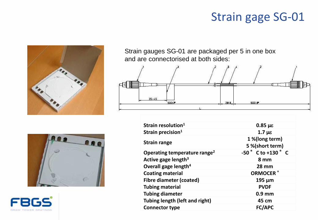
Strain gauges SG-01 are packaged per 5 in one box
and are connectorised at both sides:
Parameter Value Strain resolution1 0.85 µe
Strain precision1 1.7 µe
Strain range 1 %(long term) 5 %(short term)
Operating temperature range2 -50 °C to +130 °C Active gage length3 8 mm Overall gage length4 28 mm Coating material ORMOCER ® Fibre diameter (coated) 195 µm Tubing material PVDF Tubing diameter 0.9 mm Tubing length (left and right) 45 cm Connector type FC/APC
Box containing 5 SG-01 sensors
Strain gage SG-01

Parameter Value
Temperature resolution1 0.1°C
Temperature precision1 0.2°C
Temperature range2,3 -20 °C to +110 °C
Sensor length 58 mm
Housing diameter 5 mm
Housing material SS316
Pigtail diameter 0.9 mm
Pigtail length3 1 m
Pigtail material PVDF
Connector type FC/APC
1 Taking into account a depolarized measurement device with a 1 pm wavelength resolution and precision. 2 For the sensor and not for the connector. For the extreme temperatures, splicing is recommended. 3 Extendable on request.
• Compact temperature sensor for temperature compensation of strain measurements
• High accuracy and excellent long-term stability
• Wide temperature operating range
• Single ended configuration
Temperature probe TC-probe
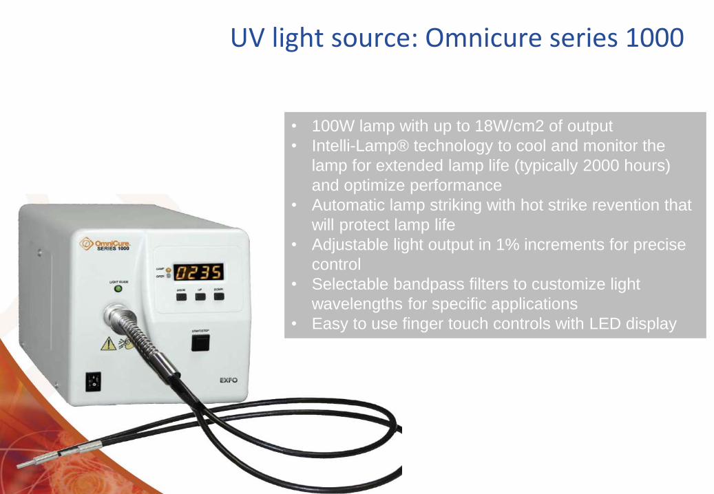
• 100W lamp with up to 18W/cm2 of output
• Intelli-Lamp® technology to cool and monitor the
lamp for extended lamp life (typically 2000 hours)
and optimize performance
• Automatic lamp striking with hot strike revention that
will protect lamp life
• Adjustable light output in 1% increments for precise
control
• Selectable bandpass filters to customize light
wavelengths for specific applications
• Easy to use finger touch controls with LED display
UV light source: Omnicure series 1000
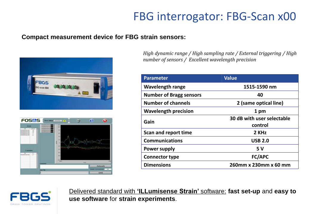
Parameter Value
Wavelength range 1515-1590 nm
Number of Bragg sensors 40
Number of channels 2 (same optical line)
Wavelength precision 1 pm
Gain 30 dB with user selectable
control
Scan and report time 2 KHz
Communications USB 2.0
Power supply 5 V
Connector type FC/APC
Dimensions 260mm x 230mm x 60 mm
High dynamic range / High sampling rate / External triggering / High number of sensors / Excellent wavelength precision
Compact measurement device for FBG strain sensors:
Delivered standard with ‘ILLumisense Strain’ software: fast set-up and easy to
use software for strain experiments.
FBG interrogator: FBG-Scan x00