Embed Size (px)
Citation preview
Faying Surface Lubrication Effects on Nut Factors
Deneen M. Taylor* and Raymond F. Morrison**
Abstract
Bolted joint analysis typically is performed using nut factors derived from textbooks and procedures from program requirement documents. Joint specific testing was performed for a critical International Space Station (ISS) joint. Test results indicate that for some configurations the nut factor may be significantly different than accepted textbook values. This paper presents results of joint specific testing to aid in determining if joint specific testing should be performed to insure required preloads are obtained.
introduction
During review of International Space Station analysis documentation and build paper it was discovered that one of the International Partners had overtorqued the installation bolts on the Common Berthing Mechanism (CBM) Ring on each of their elements. The build paper also raised questions concerning lubrication and whether or not it had been applied to the faying surfaces of the bolt head/washer in addition to the threads. The CBM is a mechanism built and qualified by Boeing and furnished to the other partners for use with the pressurized elements. Too high of a preload could overload the bolts when combined with on-orbit thermal and mechanical loads and potentially cause failure. Too low of a preload could cause the joint to gap and leak atmosphere overboard on orbit. Due to this out of configuration condition, it was decided that joint specific testing would be run to quantify the effects of the torque and lubrication.
Background
The testing was implemented to determine the nut factor, K, of three different bolt materials, A286, MP35N and lnconel in combination with A286 helicoil inserts and nuts, with and without lubrication on faying surfaces. To remove any uncertainties of previous contamination to the bolts, all bolts were cleaned before testing. All bolts are about 6.3-mm (exactly I4 inch) diameter. Countersunk CRES washers were placed under bolt heads and A286 passivated flat washers under the nuts. Helicoils and nuts came from the manufacturer with standard locking features and lubrication. Lubrication applied during testing to bolts was Braycote 81 52 oil. The bolted material is anodized aluminum. The different permutations of the tests are shown in Table 1.
Although the objective of this testing was to verify that the higher torque did not yield the bolts and to obtain actual nut factors for these specific configurations, due to the numerous tests and various configurations some interesting trends became apparent. It is important to note that the lubrication was added between cycles not just for the first cycle, reflective of the flight hardware. In addition, the max/min nut factors cited are inclusive from all previous cycles, not just the max and min from the noted cycle.
* NASA Johnson Space Center, Houston, TX **
Boeing, Huntington Beach, CA
Proceedings of the 38th Aerospace Mechanisms Symposium, Langley Research Center, May 17- 19,2006
157

Table 1. Permutations of tested bolt configurations
i Min Max Test \ Bolt / Inserthut Lubrication Tightenvia Samples Cycles / : K i K ' Bolthead / 9 10 I .18 I .56
i 10 10 I .14 \ .18
i 10 I 10 , .08 , .18
....................................................... i
........................................ ................................................................ .............................................................................. ..................................................... . . . . . . . . . . . j ................................................. i... ........................... .......................... + 4 i +
i ............................................................. i ................................................................................. 4 ......................................... ..+ ..................... .i ......................................... + ............................ * .............. Case 1-1 ~ A286 ' Helicoil I Threads only
Case 1-2 ' A286 , Helicoil
Case2-1 MP35N / Nut ; Threads only
Case2-2 1 MP35N I Nut i Threads only
Case2-3 I MP35N Nut I surfaces of bolt i
Case3-1 , Inconel718 ' Nut I surfaces of nut I
Case3-2 I Inconel718 I Nut I surfaces of nut i
I Threads and faying ' l Bolthead ~ 5 5 / .ll I .14 Case 4-1
Case 4-2 lnconel 718 Helicoil / Threads only I Bolt head / 5 I 5 1 .21 .51
j Threads and faying I Bolt head / surfaces of bolt i .................................................... .................... ............................................ ....................... .................. ......................................................
........................................................ ................................................................ ...................................................... ......................... ................................................ ......................... I Nut
/ Bolthead I 10 / 10 .23 ; .49
i- _____. i : i 4 i i 4.
2 i i I. + 4 4
................................................................. ............ ...... ........................... ................................................ ............................ . . ............................................ j + i i 4 4
i i .i
I Threads and faying Bolt head , ' Threads and faying
I 5 ' 10 i .10 ; .21
i Threadsandfaying Nut 1 4 1 I 5 ~ .12 .17
...... ............................................. ........................... . . . . . .................................................. ................................................................ ....................... ......................................................
....,
L- ! -. 4 i
Bolt head ~ 4 1 5 / .13 ~ .45 .............................................. ........................... .................................................. ...................... ............................................. ............................... ;---+ .../ ..i. 4 j 4 4
..................................................... ............................................................. .......................................................................................................................................... ..................... ......................................... ........................... ........ j + ~ i. ...I 4 i
.............................................. ............................. .............. ..................................................... c 4 ................................................................. ?urfaCeS..of.~!t ..................................................... ; i i (..
lnconel 718 1 Helicoil
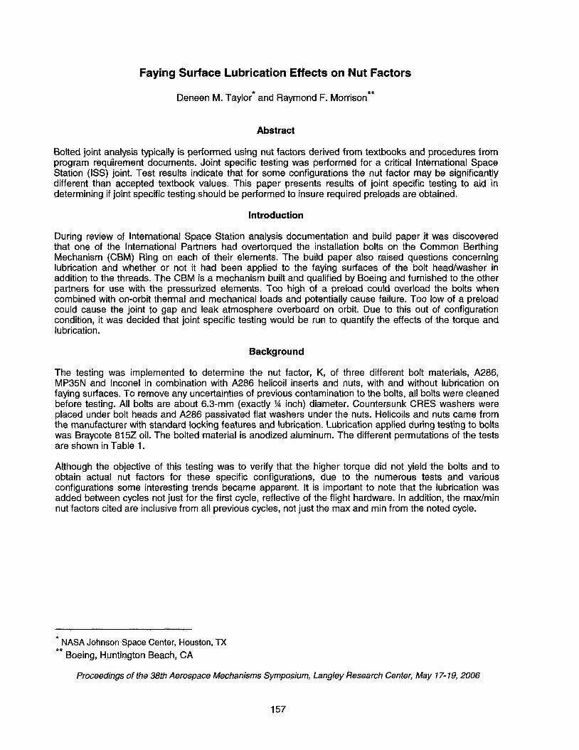
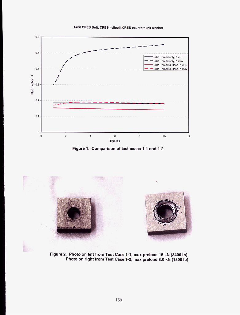
Test Cases 1-1 and 1-2 Test cases 1-1 and 1-2 compared the effects of lubrication on threads only with lubrication on threads and faying surface under bolt head for the A286 bolts. Both cases were tightened at the bolt head. Data indicates that for bolt/insert configurations, lubrication on the faying surfaces under the head of a bolt significantly reduces the maximum nut factor and the scatter (Figure 1). After 10 cycles, the faying-surface lubricated bolts had a &, = 0.18 and bin = 0.14, whereas the threads-only lubricated bolts had a K,,,, = 0.56 and Lin = 0.18. Without lubrication on faying surfaces, increasing bolt cycles also significantly increases nut factor. This is presumed to be because lack of lubrication on the faying surface induces wear under the washer, then additional cycles exacerbates the wear increasing the nut factor (Figure 2).
Test Cases 2-1.2-2 and 2-3 Test cases 2-1 and 2-2 compare the affect of tightening the MP35N bolts via nut versus tightening via bolt head. Both cases had lubrication on the threads only. Bolt tightened tests were significantly higher. After 10 cycles, nut-tightened nut factors were K,, = 0.18 and bin = 0.08. Bolt-tightened nut factors were K,, = 0.49 and Gin = 0.23. This is an increase of almost 75% (Figure 3).
Test cases 2-2 and 2-3 compared the affects of lubrication on threads only with lubrication on threads and faying surface under bolt head for the MP35N bolts. Both cases were tightened via bolt head. Data indicates that for bolts with lubrication applied only to the threads the nut factor will be much higher than for bolts with lubrication applied to the faying surfaces under the bolt head in addition to threads. After 10 cycles, the threads-only lubricated bolts had a K,, = 0.49 and Lin = 0.23 whereas the faying-surface lubricated bolts had a Lax = 0.21 and Kmin = 0.1 0. This is an increase of over 100% (Figure 4).
Test Cases 3-1 and 3-2 Test cases 3-1 and 3-2 are a comparison of tightening lnconel bolts via bolt head with tightening via nut. Both cases had lubrication added to threads and to the faying surfaces at the nut. The bolts tighten via bolt head had similar nut factors as those tightened via nut for the first cycle, but after just 2 cycles bolt- tightened cases had significantly higher maximum nut factors. Bolt-tightened cases produced nut factors of K,, = 0.45 and K,,,,,, = 0.13. Nut-tightened cases produced K,, = 0.17 and Kmin = 0.12 (Figure 5).
Test Cases 4-1 and 4-2 Test cases 4-1 and 4-2 compare the affects of lubrication on threads only with lubrication on threads and faying surface under bolt head for the lnconel bolts. Both cases were tightened via bolt head. The bolts that had lubrication both on threads and on faying surface under bolt head had lower nut factors than those bolts lubricated at threads only. After 5 cycles, the faying-surface lubricated bolts had a K,, = 0.14 and Kmin = 0.1 1 whereas the threads-only lubricated bolts had a K,,, = 0.51 and Kmin = 0.21 (Figure 6).
158
A286 CRES Bolt, CRES helicoil, CRES countersunk washer
0.6
0.5
0.4
Y i B
0.3 LL
0.2
0.1
0 0
/ /
/ - - -
- -Lube Thread only, K rnax Lube Thread & Head, K mir - -Lube Thread & Head, K ma
/ / -.-
2 4 6 8 10
Cycles
Figure 1. Comparison of test cases 1-1 and 1-2.
12
,
i . .
Figure 2. Photo on left from Test Case 1-1, max preload 15 kN (3400 Ib) Photo on right from Test Case 1-2, max preload 8.0 kN (1800 Ib)
159

0.6
0.5
0.4
Y
0.2
0.1
MP35N Bolt, A266 CRES nut, CRES countersunk washer Lubrication on Threads Only
/ - /
/ ~ .c 0
- -Tghtened via Nut, K max -Tightened via Bolt, K rnin - - Tahtened via Bolt. K max
-I--
-++- -+-e- -------
C 0 2 4 6 8 10 12
0.6
0.5
0.4
Y
5 0.3 L
s
0.2
0.1
0
Cycles
Figure 3. Comparison of test cases 2-1 and 2-2.
MP35N Bolt, A266 CRES nut, CRES countersunk washer Bolt lightened via Head
~~ -.-- _ _ _ _ ~- ._ ~ - - - - __.- - ~~~ ------- ~~~ .
/ -
- -Lube Thread only, K rnax Lube Thread & Head, K rnir
/ /
~~
0
0 2 4 6 8
Cycles
10 12
Figure 4. Comparison of test cases 2-2 and 2-3.
160

0.6
0.5
0.4
Y
0 0.3 U
z
ii L
0.2
0.1
0 0
0.6
0.5
0.4
Y L-
2 0.3 B
0.2
0.1
Inconel718 Bolt, A286 CRES nut, CRES countersunk washer Lubrication on Threads and Faying Surfaces of Nut
Tightened via Nut, K min Tightened vla Nut, K max
-Tightened via Bolt, K min _ _ - _ ._
0 0
- . 0 0
0 0
0 0
0 0
0 / /
// 0
# / ------------- 0
- 4 - -
_. .
1 2 3 4 5 Cycles
Figure 5. Comparison of test cases 3-1 and 3-2.
Inconel718 Bolt, CRES helicoil, CRES countersunk washer
L - c- - -Lube Thread only, K max
Lube Thread 8 Head, K min Lube Thread 8 Head, K ma
-e--
/- 0
/ /
/ 0
0 0 1 2 3
Cycles 4 5 6
6
Figure 6. Comparison of test cases 4-1 and 4-2.
161

Conclusion
In conclusion, bolts that were tightened via nut (test cases 2-1 and 3-2) produced similar nut factor ranges (K = 0.11 to 0.18) as those typically found in literature for “lubricated” steel bolts (K = 0.12 to 0.20) regardless if lubrication was added to the faying surface under the nut or not. In all published sources reviewed, if the term “lubricated was defined it meant lubricated at the threads and “non-lubricated” would mean no lubrication was added to “as-received condition, but bolts were not specially cleaned to remove any residuals from machining/processing. Of course, if lubrication is added to the threads it can very easily migrate to the nut faying surfaces hence explaining the similarity. However, for bolts tightened at the head, there are some significant differences. If lubrication exists on the faying surface of the bolt head (test case 1-2, 2-3 and 4-1), nut factor ranges typical for nut-tightening were produced (K = 0.1 0 to 0.21), but if there was no lubrication on the faying surface of the bolt head (test cases 1-1, 2-2, 3-1 and 4-2), the nut factor ranges were significantly larger (K = 0.18 - 0.56). It made little difference for the bolts tightened via head whether it was threaded into a nut or insert.
A fairly comprehensive literature search was performed to look for nut factor data on bolts tightened at the head or effects of additional faying surface lubrication. Nothing specific was found. However, one source had a very brief statement that acknowledged K values could be “up to 50% higher” for bolt head tightening 111. It is very clear from this testing that general “text-book nut factors values can not be assumed to be appropriate for non-lubricated faying surface bolts tightened at the bolt head.
Testing demonstrates that as early as the second cycle the nut factor increases significantly when tightened at the head without lubrication at the faying surface. This change in nut factor needs to be considered for reworking of a nonlubricated bolted joint or where a mix of installation cycles exists in a critical joint to maintain the desired preload.
Torque tension joint specific testing was not required for the majority of ISS Space Station hardware. Test results indicate that for future programs, testing should be considered for critical joints where it is not possible to apply lubrication at the faying surface.
References
1. Engineering Sciences Data Unit “Applying, Measuring and Maintaining Pretension in Steel Bo!ts.”
2. National Aeronautics and Space Administrations. “Standard, Threaded Fasteners, Torque Limits for”
3. Gibson, James N. “Torque Tension Tests for the Common Berthing Mechanism (CBM), International
4. Morrison, Raymond F. Analysis of CBM Bolts for Overtorque Condition” Boeing Report D684-12216-
5. Shigley, Joseph E., and Mischke, Charles R.(1996). Standard Handbook of Machine Design. 2”d ed.
6. Bickford, John H. (1 995). An lntroducfion to the Design and Behavior of BoltedJoints. 3rd Rev ed. New
ESDU Item Number 8601 4, July 1986
MSFC-STD-486 Rev B, November 1992.
Space Station” Boeing Report M&P-3-1638, June, 2005
01, June 2005
New York: McGraw-Hill.
York: Marcel Dekker.
1 62