Embed Size (px)
Citation preview
JOURNAL OF THEORETICAL
AND APPLIED MECHANICS
55, 2, pp. 393-406, Warsaw 2017DOI: 10.15632/jtam-pl.55.2.393
FAULTS DETECTION IN GAS TURBINE ROTOR USING VIBRATION
ANALYSIS UNDER VARYING CONDITIONS
Benrabeh Djaidir, Ahmed Hafaifa, Abdallah Kouzou
Applied Automation and Industrial Diagnostics Laboratory, Faculty of Science and Technology, University of Djelfa, Algeria
e-mail: [email protected]; [email protected]; [email protected]
Monitoring of rotating machines is a very important task in most industrial sectors, whichrequires a chosen number of performance indicators during the exploitation of such kindof equipments. Indeed, for understanding the undesirable phenomena complexity of theindustrial systems under operation, a reliable and an accurate mathematical modeling isrequired to ensure the diagnosis and the control of these phenomena. This work proposesdevelopment of a fault monitoring system of a gas turbine type GE MS 3002 based onvibration analysis technique using spectral analysis tools. The obtained results prove theeffectiveness of the presented monitoring tool approach which is applied on the gas turbine,for avoiding the operation under vibration mode and for generating optimal performanceduring the exploitation of the gas turbine.
Keywords: default bearings, dynamic behavior, faults detection, gas turbine, monitoringsystem
1. Introduction
Vibration analysis of rotating machines in industrial plants is widely used to ensure prematurefaults diagnosis before these machines may break down. Gas turbines are the most importantpivotal rotating machines belonging to the family of internal combustion engines that are usedintensively in oil and gas industrial plants. Indeed, it is used to achieve the main function ofgenerating mechanical energy in form of shaft rotation from kinetic energy of gases producedin the combustion chamber (Djaidir et al., 2015, 2016; Djeddi et al., 2015, 2016; Eshati et al.,2013; Jurado and Carpio, 2006; Kim et al., 2011). However, these machines are subject to somephenomena inducing important vibrations that can be very critical to their mechanical state.
The work presented in this paper proposes a supervision approach based on vibration ana-lysis, to ensure a permanent fault diagnosis of the studied gas turbine, where the main aim isto prevent failures that may cause malfunctions and to fulfill an optimal operation availabilityof such a machine. Indeed, there are several methods that have been used for characterizationand modeling of the gas turbine parameters. However, these methods are less exploitable for thecontrol of such systems due to its complexity. The proposed approach in this work is based onthe analysis of the magnitude and the harmonics spectrum of signals resulting from measuredvibrations on the gas turbine under different failures that may affect this kind of machine duringits normal operation.
Gas turbines are widely used in many industrial applications such as oil industry wherethey are mainly used for wells re-injection and gas transportation along the pipelines. Thesemachines are subject to various instability factors that are influencing directly their operatingperformances. Therefore, in order to improve the performances of these systems, many resear-ches previously built mathematical models that represent the real time operation state moreaccurately and instantaneously. Madhavan et al. (2014) developed a vibration model based on

394 B. Djaidir et al.
damage detection of rotor blades in a gas turbine engine. They showed that the developed modelcan be used to carry out the analysis of mechanical components failures detection of the systemunder study. Liu et al. (2015) studied the influence of large scale wind turbine blade vibrationbased on the influence of the aerodynamic effects. Usman et al. (2015) presented the impact ofoperating conditions and exhaust gas recirculation on the performance of rotors dynamics ofa gas turbine system. However, the current development of new technologies has allowed rese-archers and industrial practices to improve the performance of gas turbines and to contributeeffectively to developing new methods and algorithms for controlling of such systems. In thiscontext, many industrial monitoring systems are being developed by several researchers to en-sure fault detection, as well as for the diagnosis of defects (Ali et al., 2015; Djaidir et al., 2015,2016; Djeddi et al., 2015, 2016; Gunyaz, 2013; Krzyzynski et al., 2000; Liu et al., 2015; Sanayeand Tahani, 2010; Simani and Patton, 2008).The present paper deals with the modeling of gas turbine defects based on vibration analysis
using mathematical techniques, where a number of assumptions representing different operatingparameters of the studied gas turbines have been taken into account. In this paper, the analysisof dynamic behavior of rotor vibration of the gas turbine type GE MS 3002 is proposed. Thisgas turbine rotates at high speed up to 7100 tr/min and it is supported by bearings that may besubject to faults during normal operation, which may contribute directly to the deterioration ofthe gas turbine in a rapid manner.The obtained in this paper results show clearly the effectiveness of the presented modeling
of the defects in a gas turbine. The presented approach allows one to build a diagnostic strategybased on the vibration behavior analysis. On the other side, the experimental procedure fortracking the anomalies in the gas turbine is presented. It is based on the use of the obtainedvibration signal spectrum and the associated analysis.
2. Dynamic vibration behavior in gas turbine
Gas turbines are heavily utilized in industry, where they are used mainly for producing andensuring important mechanical energy (Ford et al., 2013; Guasch, 2013; Lee et al., 2013; Rah-moune et al., 2015). They are used for driving of fixed appliances where important output poweris required such as in electrical power generator, in powerful compressors, in powerful pumps,etc. Therefore, the analysis of dynamic behavior of the gas turbine is attracting much attentionfrom the researcher and industrialists. It is based on the study of vibration behavior of themain element of the gas turbine which is the high pressure rotor (HP) (Madhavan et al., 2014;Rahmoune et al., 2015).The vibration signal is presented by the following expression
x(t) = A sin(wt+ φ) (2.1)
where w is the frequency of vibration, φ is the phase and A the amplitude of vibration inmicrometers [µm].The vibration speed ν(t) and the vibration acceleration a(t) are obtained by differentialing
vibration expression (2.1) as follows
ν(t) =dx(t)
dt= Aw cos(wt+ φ) a(t) =
dν(t)
dt= −Aw2 sin(wt+ φ) (2.2)
Practically, all units are based on millimeters and seconds.Based on equations (2.1) and (2.2), the following expressions can be deduced
|x| = |ν|w=|a|w2
|ν| = |x|w = |a|w
|a| = |ν|w = |x|w2 (2.3)

Faults detection in gas turbine rotor using vibration analysis... 395
where x is the displacement, ν is the vibration speed, a is the vibration acceleration and w isthe frequency of vibration.Equation (2.3) highlights the importance of the choice of physical variables for data measu-
rement and monitoring of the gas turbine. Compared to the model based on speed measurement,the displacement measurements are used to reduce the high and the medium frequency vibrationeffects, which can amplify the low frequency vibration components. In this case, radial vibrationsin the gas turbine are studied in the simple case of a circular cross-section of the rotor in thetransverse position.The dominant torsional displacement is the rotation of the cross sections given by the angular
displacement α. The simplified displacement is used as follows
u1(x1, x2, x3, t) ≈ 0 u2(x1, x2, x3, t) ≈ −x3α(x1, t)u3(x1, x2, x3, t) ≈ x2α(x1, t)
(2.4)
For the deformation calculations, the Hamilton functional is used
ε11 = ε22 = ε33 = ε23 ε12 = −1
2x3∂α
∂x1ε13 =
1
2x2∂α
∂x1(2.5)
The Hamilton functional construction is given by the following equation
H(α) =
t1∫
t0
l∫
0
[1
2ρI1(∂α
∂t
)2− 12GI1( ∂α
∂x2
)2+M1α
]
dx1 dt
I1 =
∫
S
(x22 + x23) dx2 dx3
(2.6)
The rotor motion is given by
ρI1∂2α
∂2t2− ∂∂x1
(
GI1∂α
∂x1
)
=M1 ∀x1 ∈ [0, l], ∀t ∈ ℜ (2.7)
where G = E/[2(1 + ν)] is the shear modulus of the rotor in the limitat conditions x1 = 0 andx1 = l
α(0, t) = 0 GI1∂α
∂x1(0, t) = 0
α(l, t) = 0 GI1∂α
∂x1(l, t) = 0
(2.8)
The conditions in the initial state are given by α = 0 and the condition GI1 = ∂α/∂x1 = 0when no torsion at the free end is provided. The stress on the rotor surface is determined byusing the following equation
σ11σ22σ33σ23σ13σ12
=
E νE νE 0 0 0νE E νE 0 0 0νE νE E 0 0 0
0 0 E2(1+ν) 0 0 0
0 0 0 E2(1+ν) 0 0
0 0 0 0 0 E2(1+ν)
000
−x3αx1−x2αx10
(2.9)
In practice, gas turbines systems are complex and are generally non-stationary. Consequently,their non-linear behavior makes the modeling step of the vibrations very difficult. Hence, im-plementation of a reliable predictive tool is required to ensure the control and the diagnosis of

396 B. Djaidir et al.
such systems. For this purpose, vibration analysis techniques are used, tested and validated inthis paper.The vibration analysis used is based on the real vibration data collected on the studied gas
turbine at different phases of operation. For the present application, the points of measurementsare shown in Fig. 1, where a moving accelerometer is used for these measurements for bothlevels. Indeed, there are three sensors that are used with accelerometers on different positions(horizontal, vertical and axial) at each level, as shown in Fig. 1.
Fig. 1. Experimental installation of the gas turbine system
The recorded vibrations of the studied gas turbine can be quantified by three fundamentalquantities. The displacement, the speed and the acceleration. The model considered comprisestwo entrances, the room temperature and the fuel mass flow rate which is expressed as follows
mc =√∆P1
2ρµ2 =
√∆P
k⇒ mc =
1
k
√∆P (2.10)
The air mass flow ma is given by
ma = k′(P2 − P1)
ma = k′(PCD − Patm)
(2.11)
It is necessary to control the combustion of the gas turbine by regulating the ratio of theefficiency F given by
F =T3 − T2ηbCV + T3
(2.12)
The sensors are installed on the gas turbine to provide dynamic behavior measurements of thehigh pressure (HP) turbine shaft speed, the low pressure (BP) turbine shaft speed and thetemperature of the blades.
3. Gas turbine parameters modelling and analysis
All the rotating machines used in different industries applications are subject to more or lessvibrations. These vibrations are due basically to poor distribution of mobile masses, especiallyin the rotor, which is essentially caused by imperfect machining during their fabrication or alack of homogeneity of the metal constituting the rotor. Indeed, the origin of vibrations observedin a gas turbine can be caused by different phenomena such as (Galindo et al., 2013; Gunyaz,2013; Krzyzynski et al., 2000):

Faults detection in gas turbine rotor using vibration analysis... 397
• Unbalance of the rotor,• Rapid braking of the shaft,• A mechanical failure; such as a broken blade,• Permanent deformation of the rotor.
The rotating part of the gas turbine consists of two shafts on which several wheels holding theblades are mounted, where the line connection between the bodies of the two shafts is ensuredby bearings. Therefore, vibration behavior of such machines extremely depends on these compo-nents. It is obvious that each such rotating machine is exposed to dynamic excitations extremelydiverse and specific to its mode of operation. At the same time, the fixed and moving parts arevibrating structures, depending on their modal characteristics and their vibration damping ca-pacities. Each part of the system (fixed or mobile) generates dynamic vibration constraints thatcause fatigue of the rotating machine parts. It is impossible for a rotating machine which is desi-gned, even with more and more advanced materials, not to vibrate. However, the manufacturersof such machines try to improve the quality of materials and design to built rotating machinesthat can support more severe vibration constraints.The research work presented in this paper allows modeling and analysis of dynamic vibration
based on the spectral analysis by considering various defects that may occur in this type ofmachines.
3.1. Spectral analysis
The Fourier Transform (FT) can convert a periodical signal into a series sum (which may beinfinite) of sine and cosine functions. Suppose a real signal x(t) is defined with a finite energy.The Fourier Transform of the signal x(t) is defined by the following equation
FTfx(t) = X(f) = 〈x(t), e2πift〉 =+∞∫
−∞
x(t)e−2πift dt (3.1)
A discrete signal x(k) of length N presenting the number of values during a fixed interval, canbe presented as follows
X(m) =N−1∑
k=0
x(k)e−2πimk
N (3.2)
On the other side, the spectrum of an aperiodic signal is given by its FT
X(ω) = FT [x(t)] (3.3)
where FT [x(t)] is spectrum of x(t).The spectral energy density (SED) in the case of a discrete signal is defined through the
discrete Fourier transform as follows
Px(m) = |x(m)|2 Sx(m) = |X(m)| (3.4)
It can be shown that the energy of the signal, which is defined as the integral energy transferredat each instant x(t), which can also be expressed as the integral of energy contributions carriedby each frequency given by
E =
+∞∫
−∞
|x(t)|2 dt =+∞∫
−∞
|x(ω)|2 dω2π=
+∞∫
−∞
|x(f)|2 df (3.5)
398 B. Djaidir et al.
The energy spectrum of the signal is replaced by the square module of the FT of the squ-are module of cn by the spectrum of energy |x(ω)|2 = |x(f)|2 of x(t) with limT→∞ Tcn =∣
∣
∣
∫+∞−∞x(t)e−iωt dt
∣
∣
∣.
In this paper, the estimation method of the spectral density is proposed for the vibrationfaults detection and isolation in gas turbine. This method presents a good spectral analysis toolfrom the point of view of calculation and allows obtaining good results for a large class of signalsin the studied gas turbine.
3.2. Vibration analysis
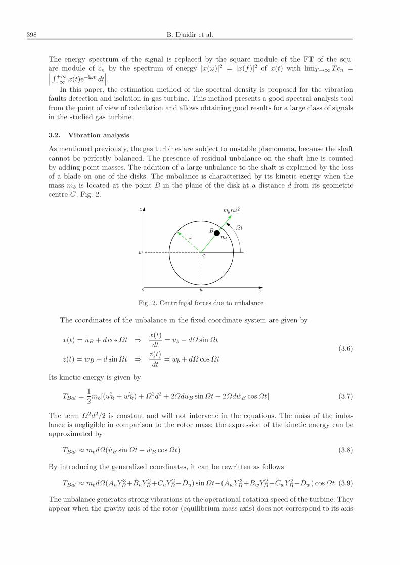
As mentioned previously, the gas turbines are subject to unstable phenomena, because the shaftcannot be perfectly balanced. The presence of residual unbalance on the shaft line is countedby adding point masses. The addition of a large unbalance to the shaft is explained by the lossof a blade on one of the disks. The imbalance is characterized by its kinetic energy when themass mb is located at the point B in the plane of the disk at a distance d from its geometriccentre C, Fig. 2.
Fig. 2. Centrifugal forces due to unbalance
The coordinates of the unbalance in the fixed coordinate system are given by
x(t) = uB + d cosΩt ⇒x(t)
dt= ub − dΩ sinΩt
z(t) = wB + d sinΩt ⇒z(t)
dt= wb + dΩ cosΩt
(3.6)
Its kinetic energy is given by
TBal =1
2mb[(u
2B + w
2B) +Ω
2d2 + 2ΩduB sinΩt− 2ΩdwB cosΩt] (3.7)
The term Ω2d2/2 is constant and will not intervene in the equations. The mass of the imba-lance is negligible in comparison to the rotor mass; the expression of the kinetic energy can beapproximated by
TBal ≈ mbdΩ(uB sinΩt− wB cosΩt) (3.8)
By introducing the generalized coordinates, it can be rewritten as follows
TBal ≈ mbdΩ(AuY 3B+BuY 2B+CuY 2B+Du) sinΩt−(AwY 3B+BwY 2B+CwY 2B+Dw) cosΩt (3.9)
The unbalance generates strong vibrations at the operational rotation speed of the turbine. Theyappear when the gravity axis of the rotor (equilibrium mass axis) does not correspond to its axis

Faults detection in gas turbine rotor using vibration analysis... 399
of rotation. This unbalance is caused by an inhomogeneous distribution of mass around the axisof rotation. In the case of turbocharger stationary motion, where the bearing part is used toguide the rotating shaft and the radial load is small and comprised primarily of the unbalance,which may be reduced if necessary. On the other side, the ball bearing damage causes severalmajor factors; such as surface material fatigue as a result of constraints that produce flakingand cracking. Furthermore, the superficial fatigue can be aggravated by some effects such asinsufficient lubrication, surface conditions, shock. Also for the elements in contact, the wear canaggravate the unstable phenomena during the operation of the machine.
For a ball bearing, Fig. 3, it comprises nb number of balls, and rotates at the frequency fr(shaft rotation frequency). The presence of a vibration defect creates shocks between the rotatingelements of the channel whose frequencies are defined by the expressions in equations (3.9) and(3.14).
Fig. 3. Geometric characteristics of the bearing
The frequencies relative to the defects on each rotating elements are functions of the passagefrequency of the rotating element in the outer ring. It is given by the following equation
fbe =frnb2
(
1− dDcosφ
)
(3.10)
The passage frequency of the rotating element in the defected inner ring, is given by the followingequation
fbi =frnb2
(
1 +d
Dcosφ
)
(3.11)
The defects frequency on the ball are given by
fB =frnb2
[
1−( d
Dcosφ
)2]
(3.12)
The passage frequency of the defected ball in the outer ring or in the inner ring is presented asfollows
fc =fr2
[
1−( d
Dcosφ
)]
(3.13)
Taking into account the modulation of the signal by the frequency fc, the above equations aremodified, so the defects in the inner ring become
fbi =frnb2
(
1 +d
Dcosφ
)
± fc (3.14)

400 B. Djaidir et al.
And the defects on the ball are expressed as
fB =frnb2
[
1−( d
Dcosφ
)2]
± fc (3.15)
This signal modulation leads to functional modeling imperfections of the examined gas turbine.In the following Section, the proposed approach based on spectral analysis at a low range fre-quency will be applied to a practical case which is considered in a real machine in the presenceof an unbalance anomaly.
4. Industrial investigations
In this study of the vibration behavior based on the analysis of measured signals on a gas turbineinstalled in the gas center of TIMZHERT, at Hassi R-Mel, south of Algeria, has been examined.Figure 4 shows the studied gas turbine with the specifications given in Table 1. This machineundergoes vibration effects observed during its operation. The measurements were carried outon this turbine via a mobile accelerometer for ensuring diagnosis of various vibration phenomenaoccuring at bearing No. 1 of the studied gas turbine. While guaranteeing the maintenance policy,vibrations are measured, processed and used for diagnosis to assess mechanical conditions of theexamined turbine.
Fig. 4. Studied GE 3002 gas turbine
Table 1. Specifications of the examined turbine
Parameter Value or symbol
Designer: General Electric GE
Type MS 3002
Serial No. 226293
HP speed axial compressor 7100 tr/min
No. floor wheel (s) HP 01
No. axial compressor stage 15
BP speed 6500 tr/min
No. BP wheel 01
Turbine power 80% 9400 CV
Fuel consumption rate (100%H 27C) 3.84m3/h
Pressure of exhaust gas 1009.3 bars
global peas 63000 k

Faults detection in gas turbine rotor using vibration analysis... 401
4.1. Applications results
In this Section, the obtained experimental results using the measurements performed onthe studied gas turbine are presented. The results were performed on each bearing (bearing 1and 4) in the vertical direction and with a rotation speed of the shaft ω = 7100 tr/min. Thecharacteristic frequencies of the bearing defects are listed in Table 2. The values given in Tablewere drawn on the basis of dimensions of the bearing and on the basis of rotation frequencyof the shaft, using the frequency fr = V (tr/min)/60 s = 7100/60 = 118.33 Hz (where V is theshaft rotation speed and nb = 15 is the number of beads).
Table 2. Characteristic frequencies of bearing defects
fr [Hz] fbe [Hz] fbi [Hz]
118.33 748 1029
According to the obtained results of measurements, it is found that the measured values onthe turbine at bearing 1 indicate the presence of vibrations in the vertical direction over a rangeof frequencies (0-10000 Hz). In order to diagnose this vibration failure, a spectral analysis hasbeen carried out. The obtained experimental results using the experimental conditions show theamplitude of the signal versus the frequency, see Figs. 5 and 5b. It is important to clarify thatthe bearing life depends on the load acting on the shaft, on the rotational speed and on thepoint of application of the force.
Fig. 5. Vibration signal: (a) of a defected bearing, (b) of a bearing with a fault located in the inner ring
The gas turbine is operated by a set of commands that support the machine during startingand accelerating till the loading phase. This automatic control helps to maintain the system to bestable. The measurements of variables such as pressure, velocity and acceleration are performedusing an instrumentation device, as shown in Fig. 6.

402 B. Djaidir et al.
Fig. 6. Position of installed sensors in the studied gas turbine
Analysis of various elements of the studied gas turbine was carried out on this installation,starting from the study of rotation speed and its frequency, which must define the parametersuseful for the proposed monitoring system. This is based on the knowledge of variations ofthe expected unstable phenomena, given by characteristic frequencies of possible defects suchas unbalance, the alignment and the attachment. Also, the resulting vibrations due to forcesdeveloped or transmitted by the bearings caused by the unbalance have been analyzed. Toanalyze these phenomena, Movilog 2 with FFT mono channel and the accelerometer with speedof 100mV/g type (HS-AM004) are used, see Figs. 7a and 7b.
Fig. 7. (a) Used accelerometer; (b) Movilog 2 with FFT mono channel
This is done with the input of balancing data for the selected rotation speed (V = 118 rpm),rotor mass (M = 3400 kg) and rotor radius (R = 75mm). At the rotational speed of 7100 rpm,where fr = 118.33 Hz in the frequency range of 0-10000 Hz, the large amplitude peaks areobserved, where fr is the rotation frequency of the shaft as shown in Fig. 8. This figure is thecontinuous display of the spectral density of the measured vibration signal within frequencyregions corresponding to proper modes of the inner ring.
The appearance of such components as the shaft of the turbine (HP rotor) runs with thedefected bearing is explained by the presence of oscillations in the torque load. These fluctuationshave the feature to occur at the same characteristic frequency of the defect. In the presentdiagnostic method, the appearance of these components is used as a reference for diagnosing thepresence of the anomalies in the studied gas turbine.
The levels shown in Tables 3 present the overall levels from the accelerometers within thefrequency ranges (1000 Hz - 10000Hz).

Faults detection in gas turbine rotor using vibration analysis... 403
Fig. 8. Vibration signal of the bearing with a fault located in the outer ring
Table 3. Overall levels from accelerometers of the studied gas turbine
SC1 KurtosisCrete Acc. [mg] Speed [mm/s]factor 10000 Hz 1000Hz Pic
3.0 4.6 208.8 2.9RV 6.9 7.0 89.8 1.3
2.9 4.5 61.8 2.6
3.0 5.0 32.0 0.2HP RH 7.0 7.0 13.3 0.1
2.9 5.2 7.0 0.2
2.7 4.5 160.6 0.7AX 6.3 7.1 69.9 0.2
2.6 4.4 45.6 0.7
Fig. 9. Amplitude of the unbalance response: (a) test 1, (b) test 2
For unbalance defects, the operator can compensate for this misalignment by adding orremoving known masses at specific locations on the rotor. These imbalance defects are mainlydue to the manufacturing errors. They can explained by the presence of poor homogeneity of thematerials used in the rotor structure. In order to verify the capacity of the system to balancingstrong unbalances, additional balancing tests were carried out. Figures 9a,b and 10a,b showresults of tests with two balancing speeds, the main goal is to reduce the overall vibration levelsat all speeds and to kept the amplitude of vibration to be stable.

404 B. Djaidir et al.
Fig. 10. Amplitude of the unbalance response: (a) test 3, (b) test 4
A misalignment is occurred when the peak amplitude is captured, generally up to 2 or3 times the rotation frequency. The vibration measurements are in function of choice of themeasurement points. In the studied case, the bearings are chosen as the points of measurementand data collecting on the examined gas turbine. Figures 11a and 11b successively present theevolution of the spectral structure (time signal) when a fault alignment is occurred.
Fig. 11. (a) Time measurement signal of the acceleration in the presence of alignment defects;(b) temporal signal without defects
At a speed of 7100 rpm, for a frequency range of 0-5000 Hz, a peak is observed (the shaft rota-tion frequency) which characterizes the misalignment fault. In Fig. 11b, the fault is directional,which is the case of the detected and identified misalignment on the gas turbine rotor. The re-sults obtained were used to analyze the signature of an axial vibration fault. Unlike unbalanced,this defect is often seen in the axial direction.
5. Conclusion
The understanding of the dynamic vibration behavior in gas turbines allows identification andlocalization of the source of the vibration anomaly as well as quantification of the defect. In thispaper, the rotor dynamics is studied to ensure the improvement of security and performanceof the studied system. The developed model allows one to analyze the dynamic behavior of aHP turbine rotor type MS 3002 rotating at a high speed and supported by bearings havingdefects that are presenting instabilities areas varying with the rotation frequency and creatingfurthermore new critical frequencies. On the other side, it is shown that some important effects

Faults detection in gas turbine rotor using vibration analysis... 405
can occur. Firstly, the wear of components regarding the rotor elements or mass distributionwhich can generate new critical speeds. Secondly, the defect in the inner ring of a bearing cangenerate the passing frequency which varies with the speed of rotation. Thirdly, the alignmenteffect manifests itself as a large amplitude component of the rotation frequency of the rotor inthe radial direction, sometimes in the axial direction in the case of a rotor cantilever.
References
1. Ali U., Font Palma C., Hughes K.J., Ingham D.B., Ma L., Pourkashanian M., 2015,Impact of the operating conditions and position of exhaust gas recirculation on the performance ofa micro gas turbine, Computer Aided Chemical Engineering, 37, 2417-2422
2. Ashour O., Khalidi A., Fadlun E., Giannini N., Pieri M., Ceccherini A., 2012, On-linemonitoring of gas turbines to improve their availability, reliability, and performance using bothprocess and vibration data, Proceeding of the 3rd Gas Processing Symposium, 334-343
3. Djaidir B., Hafaifa A., Kouzou A., 2015, Monitoring gas turbines using speedtronic Mark VIControl Systems, Pipeline and Gas Journal, 242, 10, 48-86
4. Djaidir B., Hafaifa A., Kouzou A., 2016, Vibration detection in gas turbine rotor using artifi-cial neural network, International Conference on Acoustics and Vibration ATAVI’16, March 21-23,2016, Hammamet-Tunisia
5. Djeddi A.Z., Hafaifa A., Kouzou A., Abudura S., 2016, Exploration of reliability algorithmsusing modified Weibull distribution: Application on gas turbine, International Journal of SystemAssurance Engineering and Management, DOI 10.1007/s13198-016-0480-9, First online: 12 May2016, 1-10
6. Djeddi A.Z., Hafaifa A., Salam A., 2015, Gas turbine reliability model based on tangenthyperbolic reliability function, Journal of Theoretical and Applied Mechanics, 53, 3, 723-730
7. Eshati S., Abu A., Laskaridis P., Khan F., 2013, Influence of water-air ratio on the heattransfer and creep life of a high pressure gas turbine blade, Applied Thermal Engineering, 60, 1-2,335-347
8. Ford C.L., Carrotte J.F., Walker A.D., 2013, The application of porous media to simulatethe upstream effects of gas turbine injector swirl vanes, Computers and Fluids, 77, 143-151
9. Galindo J., Fajardo P., Navarro R., Garca-Cuevas L.M., 2013, Characterization of a radialturbocharger turbine in pulsating flow by means of CFD and its application to engine modeling,Applied Energy, 103, 116-127
10. Guasch A., Quevedo J., Milne R., 2000, Fault diagnosis for gas turbines based on the controlsystem, Engineering Applications of Artificial Intelligence, 13, 4, 477-484
11. Guemana M., Hafaifa A., Rahmoune M.B., 2015, Reliability study of gas turbines for impro-ving their availability by ensuring optimal exploitation, OIL GAS European Magazine, 2, 88-91
12. Gunyaz A., 2013, A modeling and control approach to advanced nuclear power plants with gasturbines, Energy Conversion and Management, 76, 899-909
13. Hadroug N., Hafaifa A., Kouzou A., Chaibet A,, 2016, Faults detection in gas turbineusing hybrid adaptive network based fuzzy inference systems to controlling there dynamic behavior,Diagnostyka – The Journal of Polish Society of Technical Diagnostics (PSTD), 17, 4, 3-17
14. Jagaduri R.T., Radman G., 2007, Modeling and control of distributed generation systems inc-luding PEM fuel cell and gas turbine, Electric Power Systems Research, 77, 1, 83-92
15. Jurado F., Carpio J., 2006, Improving distribution system stability by predictive control of gasturbines, Energy Conversion and Management, 47, 18/19, 2961-2973
16. Kim K.H., Ko H.-J., Perez-Blanco H., 2011, Analytical modeling of wet compression of gasturbine systems, Applied Thermal Engineering, 31, 5, 834-840

406 B. Djaidir et al.
17. Krzyzynski T., Popp K., Sextro W., 2000, On some irregularities in dynamic response ofcyclic periodic structures, Chaos, Solitons and Fractals, 11, 1597-1609
18. Lee M.C., Chung J.H., Park W.S., Park S., Yonn Y., 2013, The combustion tuning metho-dology of an industrial gas turbine using a sensitivity analysis, Applied Thermal Engineering, 50,1, 714-721
19. Liu X., Lu C., Liang S., Godbole A., Chen Y., 2015, Influence of the vibration of large-scalewind turbine blade on the aerodynamic load, Energy Procedia, 75, 873-879
20. Madhavan S., Rajeev J., Sujatha C., Sekha A.S., 2014, Vibration based damage detectionof rotor blades in a gas turbine engine, Engineering Failure Analysis, 46, 26-39
21. Nikpey H., Assadi M., Breuhaus P., Mørkved P.T., 2014, Experimental evaluation andANN modeling of a recuperative micro gas turbine burning mixtures of natural gas and biogas,Applied Energy, 117, 30-41
22. Rahmoune M.B., Hafaifa A., Guemana M., 2015, Neural network monitoring system used forthe frequency vibration prediction in gas turbine, The 3rd International Conference on Control,Engineering and Information Technology CEIT’2015, 25-27 May 2015 Tlemcen, Algeria
23. Sanaye S., Tahani M., 2010, Analysis of gas turbine operating parameters with inlet fogging andwet compression processes, Applied Thermal Engineering, 30, 2/3, 234-244
24. Sextro W., Popp K., Krzyzynski T., 2001, Localization in nonlinear mistuned systems withcyclic symmetry, Nonlinear Dynamics, 25, 207-220
25. Simani S., Patton R.J., 2008, Fault diagnosis of an industrial gas turbine prototype using asystem identification approach, Control Engineering Practice, 16, 7, 769-786
Manuscript received September 28, 2015; accepted for print April 28, 2016