Embed Size (px)
Citation preview
1
Abstract— This paper introduces a particular Permanent
Magnet Motor (PMM) design methodology, considering advanced magnetic materials characteristics, for aerospace actuator applications. In this class of problems, increased electromagnetic power density, fault tolerance and high temperature withstand properties are of major importance and favored single and double layer Fractional Slot Concentrated Winding (FSCW) optimal topologies with different motor segmentation strategies have been compared. Under such strict nature of specifications, both operational and spatial, the implementation of advanced magnetic materials, particularly Vacoflux50 cobalt iron laminations and NMX-S43SH Neodymium Permanent Magnets offer great services. The optimization methodology introduced, is based on composite cost and penalty functions involving performance, efficiency, reliability, weight and thermal criteria for multi operational behavior under normal and temporary overload conditions. An appropriate Particle Swarm Optimization (PSO) algorithm ensures fast convergence of the optimization variables. The resulting optimal single layer and double layer FSCW PMM configurations present certain complementary advantages, while the former one offering greater efficiency, thermal robustness and physical segregation of the two motor parts is favored for this class of applications. The finally proposed motor configuration has been validated through measurements on a manufactured prototype.
Index Terms— aerospace actuation, fault tolerance, finite element method, particle swarm optimization, permanent magnet motors.
I. INTRODUCTION HE latest general directions in aerospace actuation applications lead to an increasing interest towards PMMs. This is basically attributed to the fact that they satisfy the
This research has received funding from the European Commission, in the
frame of “Clean Sky” Programme, Topic Nbr: JTI-CS-2010-3-SGO-02-020 under grant agreement 271850HPEM.
A. G. Sarigiannidis, and A. G. Kladas are with the School of Electrical and Computer Engineering, Laboratory of Electrical Machines and Power Electronics, National Technical University of Athens, 15780 Zografou Athens, Greece (emails: [email protected], [email protected]).
M. E. Beniakar is with ABB Corporate Research, Västerås, Sweden (email: [email protected]).
P. E. Kakosimos is with the Department of Electrical and Computer Engineering, Texas A&M University at Qatar, Education City, Doha, Qatar (email: [email protected]). L. Papini and C. Gerada are with the Power Electronics, Machines and Control Group Department of Electrical and Electronic Engineering, The University of Nottingham, NG7 2RD Nottingham, U.K. (emails: [email protected], [email protected]).
spatial limitations and constraints, dictated by the strict nature of such applications. High efficiency, high torque density and excellent transient behavior are issues of crucial importance in aerospace applications [1]-[5]. The independent and strong excitation system produced by the PMs, enables the substantial overloading of the motor, while it provides higher power density values, in comparison with other potential competitors like Switch Reluctance or Induction motors. Furthermore, PMMs exhibit improved transient behavior and manufactory simplicity, due to the absence of copper in the rotor. Moreover, the high torque density values, in conjunction with the advances in PM rare-earth materials technologies, result in high efficient motors due to lower stator currents for the same torque specifications, compared with other motor types [6]. The extremely strict nature of the specifications, both operational and spatial, of the specific aerospace application has highlighted the necessity of the thorough investigation of the actuator operating cycle and behavior as well as their systematized optimization [4-7]. Furthermore, the critical nature of aerospace applications requires a high amount of system redundancy, extended analysis and assessment of the fault tolerance capability of the electric drive-train [8-11].
In this paper, a detailed PMM design optimization technique, regarding two distinct operating conditions, for a fault-tolerant Electromechanical Actuation (EMA) system for a helicopter swash plate, is developed. In order to meet helicopter safety regulations, the actuator motor system should be conveniently internally segmented, in order to increase redundancy and fault tolerance. Two candidate segmentation strategies, axial (AS) and circumferential (CS) segmentations are adopted and both schematics are illustrated in Fig. 1. In the first type of segmentation, two separate stators in common motor housing are implemented, employing Single Layer (SL) FSCW, supplied by separate inverter for each motor unit. In the second type, the fault tolerance capability is achieved by the Double Layer (DL) FSCW, which supplies each winding layer by a separate 3-phase inverter. It may be noted that in both redundancy cases considered, two separate inverters are implemented. Initially, the optimization process will be applied to both actuators. In a next step, geometrically optimized motor configurations are evaluated in terms of electromagnetic, thermal, transient and total motor weight performance. Finally, the effectiveness of the proposed design methodology is validated through experimental results.
Fault Tolerant Design of Fractional Slot Winding Permanent Magnet Aerospace Actuator
Athanasios G. Sarigiannidis, Student Member, IEEE, Minos E. Beniakar, Panagiotis E. Kakosimos, Antonios.G. Kladas, Senior Member, IEEE, Luca Papini, and Chis Gerada, Senior Member, IEEE
T
2
(a) (b)
Fig. 1. 3D actuator schematic. (a) AS-SL FSCW topology. (b) CS-DL FSCW topology.
II. ACTUATOR SPECIFICATIONS The application considered comprises four vertically
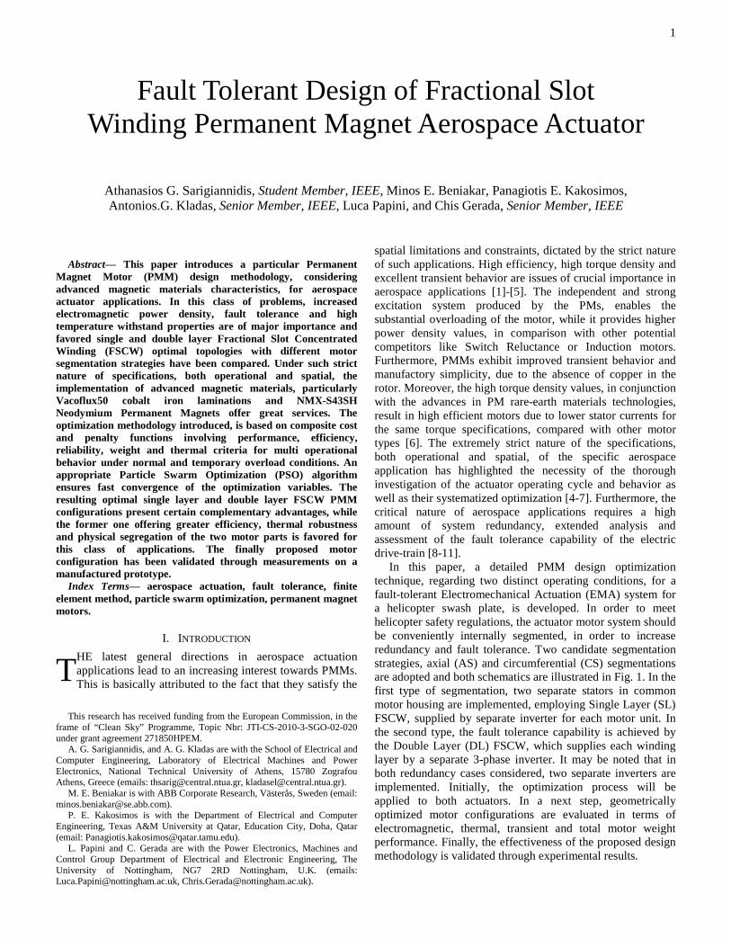
arranged and equidistantly spaced actuators for the operation of a three degree of freedom helicopter swash plate, each of them containing one motor with appropriate segmentation strategy, as shown in Fig. 1. The system operates against aerodynamic forces caused at the rotor blades and exerted on the rotating upper ring of the swash plate through pitch links. The stationary lower ring of the swash plate is positioned by the four EMAs. All actuators are simultaneously active to achieve a minimum of nominal loading. The provided redundancy allows for the malfunction of one actuator unit, the three remaining EMAs safely continuing control of the swash plate with reduced performance. For this reason, each actuator is fitted with a disconnect device, decoupling the output shaft from the mechanical drive train, in case of a mechanical jam. After disconnection of one actuator the swash plate is still safely controlled by the remaining three actuators. However, the time needed for disconnection is critical regarding stability and stress and therefore imposes strict requirements in terms of torque and speed for each actuator motor. The continuous and temporary peak torque with speed curves are shown in Fig. 2. Continuous torque is required in steady-state operation of the motor, maintaining the actuator under a specific position. The temporary maximum torque corresponds to an abrupt maneuvering of the helicopter, or in case of a mechanical jam as described above. Therefore, two different modes of operation are considered for the PMM, as tabulated in Table I. The specified torque under normal operation is about two times less compared to the extreme operating condition. A respective increase in rotor speed is also evident. The duration of the extreme mode of operation can exceed five minutes.
Fig. 2. Specified torque versus speed curve of the actuator motor.
Under the strict nature of the specifications considered, both operational and spatial, tabulated in Table I, the selection of
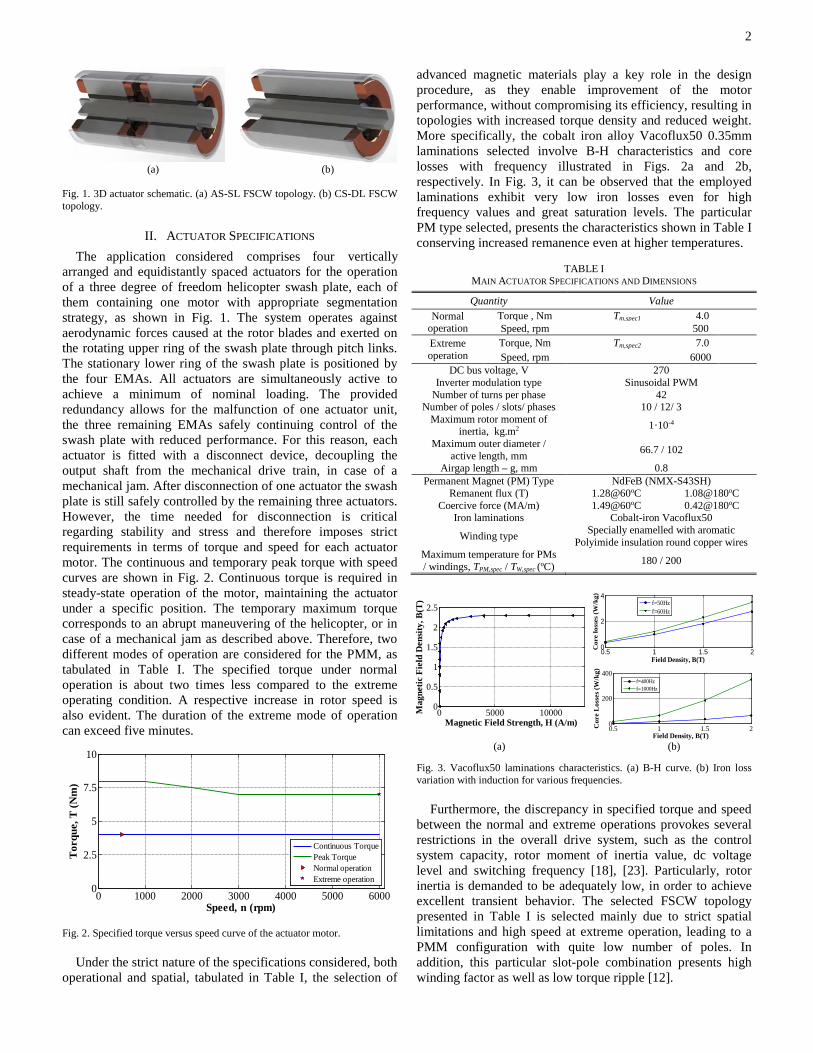
advanced magnetic materials play a key role in the design procedure, as they enable improvement of the motor performance, without compromising its efficiency, resulting in topologies with increased torque density and reduced weight. More specifically, the cobalt iron alloy Vacoflux50 0.35mm laminations selected involve B-H characteristics and core losses with frequency illustrated in Figs. 2a and 2b, respectively. In Fig. 3, it can be observed that the employed laminations exhibit very low iron losses even for high frequency values and great saturation levels. The particular PM type selected, presents the characteristics shown in Table I conserving increased remanence even at higher temperatures.
TABLE I
MAIN ACTUATOR SPECIFICATIONS AND DIMENSIONS
Quantity Value Normal
operation Torque , Nm Tm,spec1 4.0 Speed, rpm 500
Extreme operation
Torque, Nm Tm,spec2 7.0 Speed, rpm 6000
DC bus voltage, V 270 Inverter modulation type Sinusoidal PWM
Number of turns per phase 42 Number of poles / slots/ phases 10 / 12/ 3
Maximum rotor moment of inertia, kg.m2 1·10-4
Maximum outer diameter / active length, mm 66.7 / 102
Airgap length – g, mm 0.8 Permanent Magnet (PM) Type NdFeB (NMX-S43SH)
Remanent flux (T) 1.28@60oC 1.08@180oC Coercive force (MA/m) 1.49@60oC 0.42@180oC
Iron laminations Cobalt-iron Vacoflux50
Winding type Specially enamelled with aromatic Polyimide insulation round copper wires
Maximum temperature for PMs / windings, TPM,spec / TW,spec (oC) 180 / 200
(a) (b)
Fig. 3. Vacoflux50 laminations characteristics. (a) B-H curve. (b) Iron loss variation with induction for various frequencies. Furthermore, the discrepancy in specified torque and speed between the normal and extreme operations provokes several restrictions in the overall drive system, such as the control system capacity, rotor moment of inertia value, dc voltage level and switching frequency [18], [23]. Particularly, rotor inertia is demanded to be adequately low, in order to achieve excellent transient behavior. The selected FSCW topology presented in Table I is selected mainly due to strict spatial limitations and high speed at extreme operation, leading to a PMM configuration with quite low number of poles. In addition, this particular slot-pole combination presents high winding factor as well as low torque ripple [12].
0 1000 2000 3000 4000 5000 60000
2.5
5
7.5
10
Speed, n (rpm)
Tor
que,
T (N
m)
Continuous TorquePeak TorqueNormal operationExtreme operation
0 5000 100000
0.5
1
1.5
2
2.5
Magnetic Field Strength, H (A/m)
Mag
netic
Fie
ld D
ensi
ty, B
(T)
0.5 1 1.5 20
2
4
Field Density, B(T)
Cor
e lo
sses
(W/k
g)
f=50Hzf=60Hz
0.5 1 1.5 20
200
400
Field Density, B(T)
Cor
e L
osse
s (W
/kg)
f=400Hzf=1000Hz
3
III. PROPOSED DESIGN METHODOLOGY
A. Preliminary Design In a first step, an estimation of the actuator structure and
performance is achieved by considering classical machine design analytical techniques [4-6]. Such an analytical approach does not enable detailed design optimization, due to the approximate nature of the electromagnetic field representation, but it delivers a suboptimum set of design variables adequately close to the region of the global optimum. It should be noted that this preliminary procedure is of crucial importance, as it can reduce the range of the design variables domain. The initial design is focused on the satisfaction of the fundamental spatial limitations and operational specifications as tabulated on Table I and is based on the analysis performed in [5].
B. Critical Design-Optimization procedure For the determination of the final motor geometry adopted,
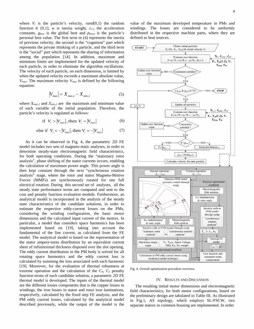
a particular optimization algorithm, coupled with an external parametric fixed-step 2-D FE model, is introduced. Finally, a PSO methodology is employed, due to its inherent benefits among the other stochastic search algorithms [15], [16]. More specifically, PSO technique presents significant benefits, such as the reduced computational time and adjusted parameters. Moreover, PSO does not depend on the selected initial solution so as to start its iteration process [13]. The flowchart of the proposed PMMs optimization procedure is illustrated in Fig. 4.
A single objective PSO optimization routine, focusing on the maximization of performance, power quality and minimization of total losses and weight, by using appropriate weight coefficients, is executed through the proposed optimization methodology. The optimizer iteratively calls a parametric 2D FE model of the PMM, in order to compute its electromagnetic field characteristics, necessary for the evaluation of the composite cost function terms, through a two-step analysis, as shown in Fig. 4. The design particle vector applied to parametric FE model at jth iteration is:
, , i j mag w bi ag so i j
X T T R wθ = (1)
where θmag is PM angle, Tw the tooth width, Tbi the back iron thickness, Rag the mean air-gap radius and wso the slot opening. The design variable limits are presented in Table II. The design variables limits are fixed at the preliminary design stage and are selected by combining construction constraints and variables differences not exceeding 25% of the initial design values, constituting a convenient compromise between accuracy of the optimal solution and overall convergence speed. The composite cost function, evaluated for each particle of the population, is expressed as follows:
1 1 2 2 3 3 4 4
,01 2 3 4
,0 ,0 ,0 0
0.5 0.5 ripplem total V
m total V ripple
F w F w F w F w F
TT P THD mF w w w w
T P THD T m
= ⋅ ⋅ ⋅ ⋅
= ⋅ + ⋅ + ⋅ ⋅ + ⋅ + ⋅
+ + + ⇒
(2)
where w1-4 represents the weight coefficients ∈ (0,1), Tm the mean produced electromagnetic torque, Ptotal the total losses,
THDV is the stator voltage total harmonic distortion, Tripple the torque ripple and m the total actuator mass. The zero indexed term refers to the characteristics of the preliminary design. Cost function terms are calculated for the nominal operation, as it is the major and most frequent operating condition of the actuator. The phase inductances and the inertia constant for every respective motor design are evaluated during the optimization procedure. Although the dynamic response is not included directly in the composite cost function of the implemented optimization procedure, the mechanical and electrical dynamic characteristics are considered. Furthermore, the design variable limits are adapted to geometrical constraints, in order to guarantee mechanical robustness and avoid exceeding the maximum moment of inertia, as presented in Table I.
TABLE II
DESIGN VARIABLES LIMITS
However, the proposed optimization algorithm takes into consideration both nominal and extreme operating conditions through the introduction of appropriate constraints. In particular, a penalty function, expressed as follows, is iteratively calculated, for each particle. The penalty function terms are associated with the specified mean torque at normal Tm,spec1 and extreme Tm,spec2 operation, the fundamental stator voltage value at the high speed operation Vspec, defined by the supply dc link voltage and the sinusoidal PWM technique, and the maximum PMs TPM,spec and winding TW,spec temperatures at the extreme operation, as tabulated in Table I. If at least one constraint term value exceeds the 1.03, the respective particle is rejected as personal or global optimum for this iteration. The constraints involved in the optimization procedure are defined in terms of ratios providing a convenient per unit equivalent representation of the results. This does not affect the nature of the procedure or of the results while it facilitates the solution evaluation process.
[ ]1 2 3 4 5
, ,
, 1 , 2 ,s ,
m nom m ovl WPM
m spec m spec spec PM pec W spec
C C C C C C
T T TTV
T T T TV
=
=
=
(3)
where the indexes nom and ovl indicate the nominal and extreme operating condition, respectively.
In the process of velocity calculation for each particle, the star neighborhood topology is adopted, due to its faster convergence than other social structures [15], [17]. Moreover, the strict nature of the penalty function expressed in (3) enhances the necessity of a global than a local best to be considered as “neighbor”, for each particle. The velocity is calculated by (4).
( )( )
1 ,
2
(0,1)
(0,1)i i best i i
best i
V w V c rand p X
c rand g X
= ⋅ + ⋅ ⋅ −
+ ⋅ ⋅ − (4)
Winding Topology SL-FSCW DL-FSCW θmag (degrees) [23.4-34.9] [23.4-34.9]
Tw (mm) [3.2-3.9] [3.2-3.85] Tbi (mm) [2.2-2.8] [2.2-2.7] Rag (mm) [13.6-16.5] [13.6-16.5] wso (mm) [2.2-4.5] [2.3-4.5]
4
where Vi is the particle’s velocity, rand(0,1) the random function ∈ [0,1], w is inertia weight, c1,2 the acceleration constants, gbest is the global best and pbest,i is the particle’s personal best value. The first term in (4) represents the inertia of previous velocity, the second is the “cognition” part which represents the private thinking of a particle, and the third term is the “social” part which represents the sharing of information among the population [14]. In addition, maximum and minimum limits are implemented for the updated velocity of each particle, in order to eliminate the algorithm oscillations. The velocity of each particle, on each dimension, is limited by when the updated velocity exceeds a maximum absolute value, Vmax. The maximum velocity Vmax is defined by the following equation:
,1 ,1max max minV X X= − (5)
where Xmax,1 and Χmin,1 are the maximum and minimum value of each variable of the initial population. Therefore, the particle’s velocity is regulated as follows:
, theif n i max i maxV V V V> = (6)
else if , then i max i maxV V V V= −< − (7)
As it can be observed in Fig. 4, the parametric 2D FE model includes two sets of magneto-static analyses, in order to determine steady-state electromagnetic field characteristics, for both operating conditions. During the “stationary rotor analysis”, phase shifting of the stator currents occurs, enabling the calculation of maximum power angle. This power angle is then kept constant through the next “synchronous rotation analysis” stage, where the rotor and stator Magneto-Motive Forces (MMFs) are synchronously rotated for one full electrical rotation. During this second set of analyses, all the steady state performance terms are computed and sent to the cost and penalty function evaluation module. Furthermore, an analytical model is incorporated in the analysis of the steady state characteristics of the candidate solutions, in order to estimate the respective eddy-current losses on the PMs, considering the winding configuration, the basic motor dimensions and the calculated input current of the motors. In particular, a model that considers space harmonics has been implemented based on [19], taking into account the fundamental of the line current, as calculated from the FE model. The analytical model is based on the representation of the stator ampere-turns distribution by an equivalent current sheet of infinitesimal thickness disposed over the slot opening. The eddy current distribution in the PM body is solved for all rotating space harmonics and the eddy current loss is calculated by summing the loss associated with each harmonic [19]. Moreover, for the evaluation of thermal robustness at extreme operation and the calculation of the C4, C5 penalty function terms of each candidate solution, a parametric 2D FE thermal model is developed. The inputs of the thermal model are the different losses components that is the copper losses in windings, the iron losses in stator and rotor iron laminations, respectively, calculated by the fixed step FE analysis, and the PM eddy current losses, calculated by the analytical model described previously, while the output of the model is the
value of the maximum developed temperature in PMs and windings. The losses are considered to be uniformly distributed in the respective machine parts, where they are defined as heat sources.
Fig. 4. Overall optimization procedure overview.
IV. RESULTS AND DISCUSSION The resulting initial motor dimensions and electromagnetic
field characteristics, for both motor configurations, based on the preliminary design are tabulated in Table III. As illustrated in Fig.1, AS topology, which employs SL-FSCW, two separate stators in common housing are implemented. In order
5
TABLE III SL AND DL FSCW TOPOLOGIES-INITIAL DESIGN CHARACTERISTICS
FROM PRELIMINARY DESIGN
to reduce the computational cost of the respective 2-D FE analysis, the whole active length of the motor, taken into consideration the double end windings value only for the calculation of copper losses. Such an assumption does not compromise on the accuracy of the resulting steady state motor characteristics. The copper fill factor is considered as 0.5, which is a typical value for SL FSCW configurations at these power ratings [12].
For the CS - DL FSCW case, the copper fill factor coefficient is expected to be 0.45, due to the interface insulation in the slots. This approach leads to higher current density in the windings, compared to AS topology, in order to meet the torque specifications. From the results summarized in Table III, it can be observed that the initial design meets the specifications, for both motor topologies. However, the quite low efficiency value at nominal operation, leads the optimization algorithm to give particular focus on the minimization of the total losses. Therefore, the weights coefficients applied to (2) are assigned as:
[ ] [ ]1 2 3 4w w w w 0.2 0.35 0.15 0.3 = (8)
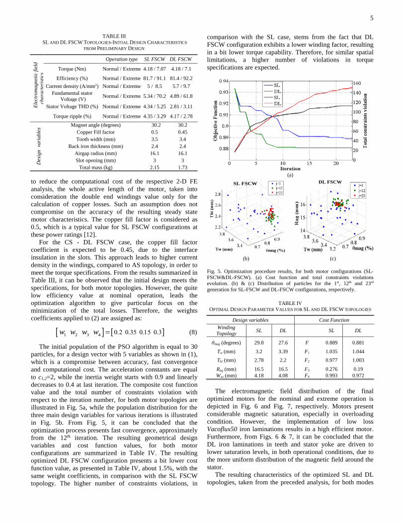
The initial population of the PSO algorithm is equal to 30 particles, for a design vector with 5 variables as shown in (1), which is a compromise between accuracy, fast convergence and computational cost. The acceleration constants are equal to c1,2=2, while the inertia weight starts with 0.9 and linearly decreases to 0.4 at last iteration. The composite cost function value and the total number of constraints violation with respect to the iteration number, for both motor topologies are illustrated in Fig. 5a, while the population distribution for the three main design variables for various iterations is illustrated in Fig. 5b. From Fig. 5, it can be concluded that the optimization process presents fast convergence, approximately from the 12th iteration. The resulting geometrical design variables and cost function values, for both motor configurations are summarized in Table IV. The resulting optimized DL FSCW configuration presents a bit lower cost function value, as presented in Table IV, about 1.5%, with the same weight coefficients, in comparison with the SL FSCW topology. The higher number of constraints violations, in
comparison with the SL case, stems from the fact that DL FSCW configuration exhibits a lower winding factor, resulting in a bit lower torque capability. Therefore, for similar spatial limitations, a higher number of violations in torque specifications are expected.
(a)
(b) (c)
Fig. 5. Optimization procedure results, for both motor configurations (SL-FSCW&DL-FSCW). (a) Cost function and total constraints violations evolution. (b) & (c) Distribution of particles for the 1st, 12th and 23rd generation for SL-FSCW and DL-FSCW configurations, respectively.
TABLE IV OPTIMAL DESIGN PARAMETER VALUES FOR SL AND DL FSCW TOPOLOGIES
Design variables Cost Function Winding Topology SL DL SL DL
θmag (degrees) 29.8 27.6 F 0.889 0.881
Tw (mm) 3.2 3.39 F1 1.035 1.044 Tbi (mm) 2.78 2.2 F2 0.977 1.003
Rag (mm) 16.5 16.5 F3 0.276 0.19 Wso (mm) 4.18 4.08 F4 0.993 0.972
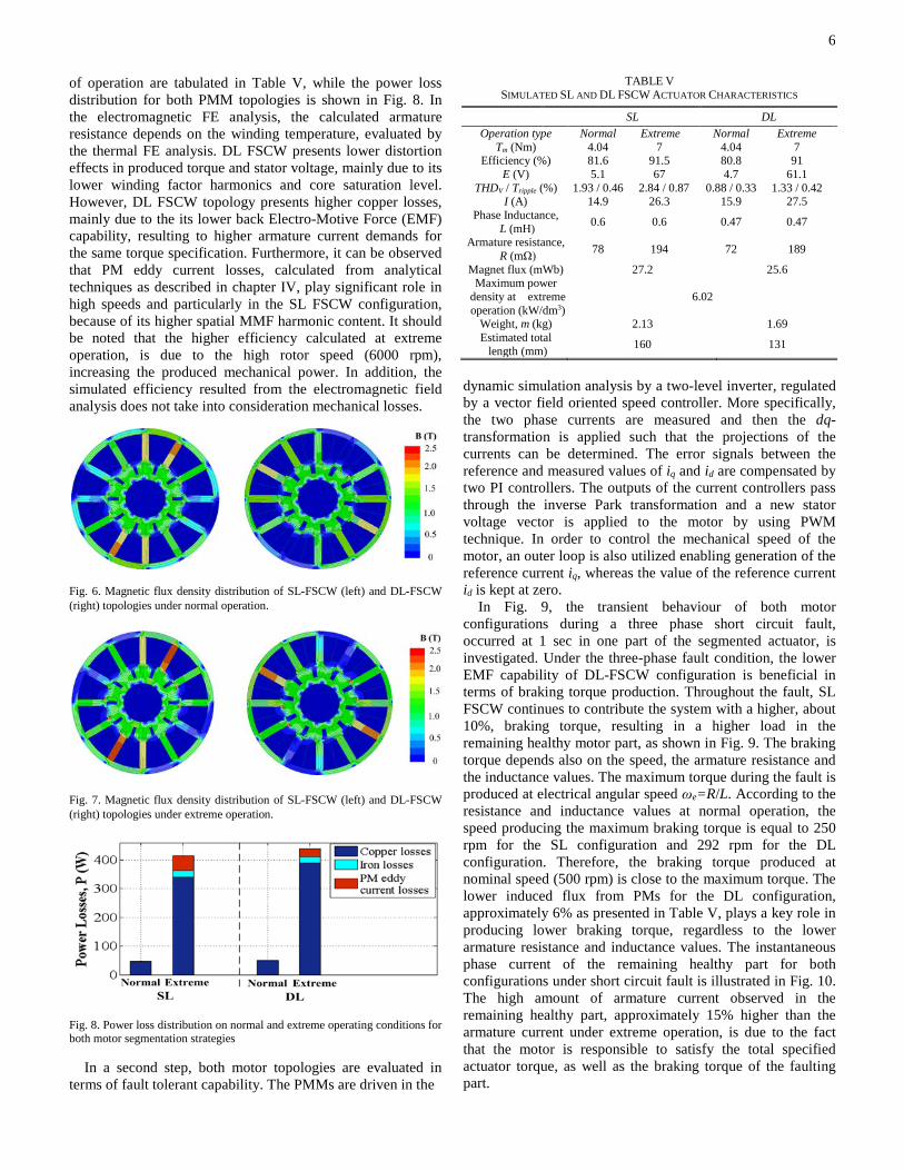
The electromagnetic field distribution of the final
optimized motors for the nominal and extreme operation is depicted in Fig. 6 and Fig. 7, respectively. Motors present considerable magnetic saturation, especially in overloading condition. However, the implementation of low loss Vacoflux50 iron laminations results in a high efficient motor. Furthermore, from Figs. 6 & 7, it can be concluded that the DL iron laminations in teeth and stator yoke are driven to lower saturation levels, in both operational conditions, due to the more uniform distribution of the magnetic field around the stator.
The resulting characteristics of the optimized SL and DL topologies, taken from the preceded analysis, for both modes
SL FSCW DL FSCW
Elec
trom
agne
tic fi
eld
char
acte
risti
cs
Operation type SL FSCW DL FSCW
Torque (Nm) Normal / Extreme 4.18 / 7.07 4.18 / 7.1
Efficiency (%) Normal / Extreme 81.7 / 91.1 81.4 / 92.2 Current density (A/mm2) Normal / Extreme 5 / 8.5 5.7 / 9.7
Fundamental stator Voltage (V) Normal / Extreme 5.34 / 70.2 4.89 / 61.8
Stator Voltage THD (%) Normal / Extreme 4.34 / 5.25 2.81 / 3.11
Torque ripple (%) Normal / Extreme 4.35 / 3.29 4.17 / 2.78
Des
ign
var
iabl
es Magnet angle (degrees) 30.2 30.2
Copper Fill factor 0.5 0.45 Tooth width (mm) 3.5 3.4
Back iron thickness (mm) 2.4 2.4 Airgap radius (mm) 16.1 16.1 Slot opening (mm) 3 3
Total mass (kg) 2.15 1.73
6
of operation are tabulated in Table V, while the power loss distribution for both PMM topologies is shown in Fig. 8. In the electromagnetic FE analysis, the calculated armature resistance depends on the winding temperature, evaluated by the thermal FE analysis. DL FSCW presents lower distortion effects in produced torque and stator voltage, mainly due to its lower winding factor harmonics and core saturation level. However, DL FSCW topology presents higher copper losses, mainly due to the its lower back Electro-Motive Force (EMF) capability, resulting to higher armature current demands for the same torque specification. Furthermore, it can be observed that PM eddy current losses, calculated from analytical techniques as described in chapter IV, play significant role in high speeds and particularly in the SL FSCW configuration, because of its higher spatial MMF harmonic content. It should be noted that the higher efficiency calculated at extreme operation, is due to the high rotor speed (6000 rpm), increasing the produced mechanical power. In addition, the simulated efficiency resulted from the electromagnetic field analysis does not take into consideration mechanical losses.
Fig. 6. Magnetic flux density distribution of SL-FSCW (left) and DL-FSCW (right) topologies under normal operation.
Fig. 7. Magnetic flux density distribution of SL-FSCW (left) and DL-FSCW (right) topologies under extreme operation.
Fig. 8. Power loss distribution on normal and extreme operating conditions for both motor segmentation strategies
In a second step, both motor topologies are evaluated in terms of fault tolerant capability. The PMMs are driven in the
TABLE V SIMULATED SL AND DL FSCW ACTUATOR CHARACTERISTICS
SL DL Operation type Normal Extreme Normal Extreme
Tm (Nm) 4.04 7 4.04 7 Efficiency (%) 81.6 91.5 80.8 91
E (V) 5.1 67 4.7 61.1 THDV / Tripple (%) 1.93 / 0.46 2.84 / 0.87 0.88 / 0.33 1.33 / 0.42
I (A) 14.9 26.3 15.9 27.5 Phase Inductance,
L (mΗ) 0.6 0.6 0.47 0.47
Armature resistance, R (mΩ) 78 194 72 189
Magnet flux (mWb) 27.2 25.6 Maximum power
density at extreme operation (kW/dm3)
6.02
Weight, m (kg) 2.13 1.69 Estimated total
length (mm) 160 131
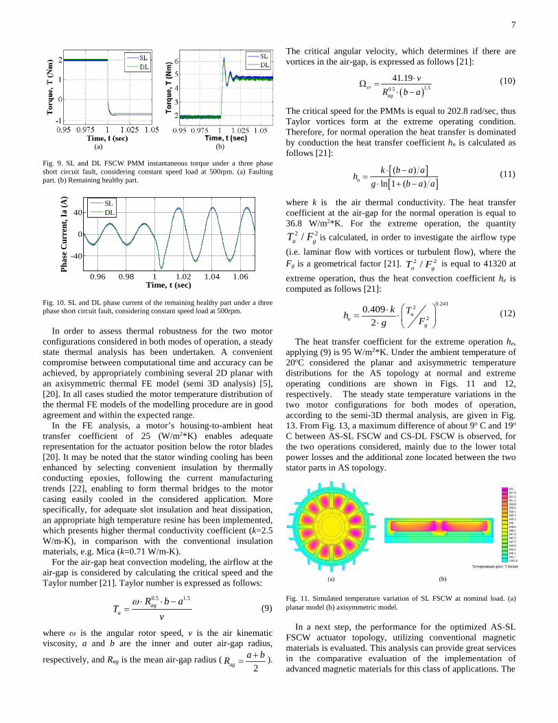
dynamic simulation analysis by a two-level inverter, regulated by a vector field oriented speed controller. More specifically, the two phase currents are measured and then the dq-transformation is applied such that the projections of the currents can be determined. The error signals between the reference and measured values of iq and id are compensated by two PI controllers. The outputs of the current controllers pass through the inverse Park transformation and a new stator voltage vector is applied to the motor by using PWM technique. In order to control the mechanical speed of the motor, an outer loop is also utilized enabling generation of the reference current iq, whereas the value of the reference current id is kept at zero. In Fig. 9, the transient behaviour of both motor configurations during a three phase short circuit fault, occurred at 1 sec in one part of the segmented actuator, is investigated. Under the three-phase fault condition, the lower EMF capability of DL-FSCW configuration is beneficial in terms of braking torque production. Throughout the fault, SL FSCW continues to contribute the system with a higher, about 10%, braking torque, resulting in a higher load in the remaining healthy motor part, as shown in Fig. 9. The braking torque depends also on the speed, the armature resistance and the inductance values. The maximum torque during the fault is produced at electrical angular speed ωe=R/L. According to the resistance and inductance values at normal operation, the speed producing the maximum braking torque is equal to 250 rpm for the SL configuration and 292 rpm for the DL configuration. Therefore, the braking torque produced at nominal speed (500 rpm) is close to the maximum torque. The lower induced flux from PMs for the DL configuration, approximately 6% as presented in Table V, plays a key role in producing lower braking torque, regardless to the lower armature resistance and inductance values. The instantaneous phase current of the remaining healthy part for both configurations under short circuit fault is illustrated in Fig. 10. The high amount of armature current observed in the remaining healthy part, approximately 15% higher than the armature current under extreme operation, is due to the fact that the motor is responsible to satisfy the total specified actuator torque, as well as the braking torque of the faulting part.
7
(a) (b)
Fig. 9. SL and DL FSCW PMM instantaneous torque under a three phase short circuit fault, considering constant speed load at 500rpm. (a) Faulting part. (b) Remaining healthy part.
Fig. 10. SL and DL phase current of the remaining healthy part under a three phase short circuit fault, considering constant speed load at 500rpm.
In order to assess thermal robustness for the two motor configurations considered in both modes of operation, a steady state thermal analysis has been undertaken. A convenient compromise between computational time and accuracy can be achieved, by appropriately combining several 2D planar with an axisymmetric thermal FE model (semi 3D analysis) [5], [20]. In all cases studied the motor temperature distribution of the thermal FE models of the modelling procedure are in good agreement and within the expected range.
In the FE analysis, a motor’s housing-to-ambient heat transfer coefficient of 25 (W/m2*K) enables adequate representation for the actuator position below the rotor blades [20]. It may be noted that the stator winding cooling has been enhanced by selecting convenient insulation by thermally conducting epoxies, following the current manufacturing trends [22], enabling to form thermal bridges to the motor casing easily cooled in the considered application. More specifically, for adequate slot insulation and heat dissipation, an appropriate high temperature resine has been implemented, which presents higher thermal conductivity coefficient (k=2.5 W/m-K), in comparison with the conventional insulation materials, e.g. Mica (k=0.71 W/m-K).
For the air-gap heat convection modeling, the airflow at the air-gap is considered by calculating the critical speed and the Taylor number [21]. Taylor number is expressed as follows:
0.5 1.5ag
a
R b aT
vω ⋅ ⋅ −
= (9)
where ω is the angular rotor speed, v is the air kinematic viscosity, a and b are the inner and outer air-gap radius,
respectively, and Rag is the mean air-gap radius (2ag
a bR += ).
The critical angular velocity, which determines if there are vortices in the air-gap, is expressed as follows [21]:
( )1.50.5
41.19cr
ag
vR b a
⋅Ω =
⋅ − (10)
The critical speed for the PMMs is equal to 202.8 rad/sec, thus Taylor vortices form at the extreme operating condition. Therefore, for normal operation the heat transfer is dominated by conduction the heat transfer coefficient hn is calculated as follows [21]:
[ ][ ]( )
ln 1 ( )n
k b a ah
g b a a⋅ −
=⋅ + −
(11)
where k is the air thermal conductivity. The heat transfer coefficient at the air-gap for the normal operation is equal to 36.8 W/m2*K. For the extreme operation, the quantity
2 2/a gT F is calculated, in order to investigate the airflow type (i.e. laminar flow with vortices or turbulent flow), where the Fg is a geometrical factor [21]. 2 2/a gT F is equal to 41320 at extreme operation, thus the heat convection coefficient he is computed as follows [21]:
0.241
2
20.409
2a
eg
k Th Fg ⋅
= ⋅ ⋅ (12)
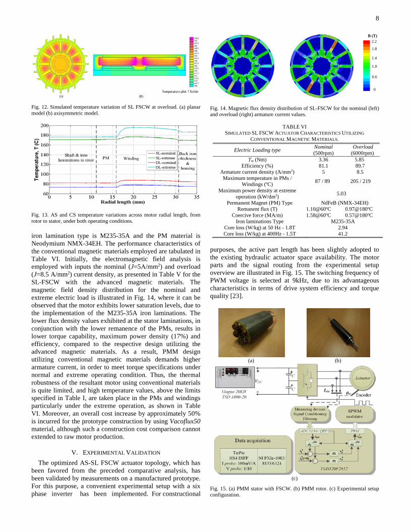
The heat transfer coefficient for the extreme operation he, applying (9) is 95 W/m2*K. Under the ambient temperature of 20oC considered the planar and axisymmetric temperature distributions for the AS topology at normal and extreme operating conditions are shown in Figs. 11 and 12, respectively. The steady state temperature variations in the two motor configurations for both modes of operation, according to the semi-3D thermal analysis, are given in Fig. 13. From Fig. 13, a maximum difference of about 9o C and 19o C between AS-SL FSCW and CS-DL FSCW is observed, for the two operations considered, mainly due to the lower total power losses and the additional zone located between the two stator parts in AS topology.
Fig. 11. Simulated temperature variation of SL FSCW at nominal load. (a) planar model (b) axisymmetric model. In a next step, the performance for the optimized AS-SL FSCW actuator topology, utilizing conventional magnetic materials is evaluated. This analysis can provide great services in the comparative evaluation of the implementation of advanced magnetic materials for this class of applications. The
0.96 0.98 1 1.02 1.04 1.06
-40
0
40
Time, t (sec)
Phas
e Cur
rent
, Ia
(A)
SLDL
8
Fig. 12. Simulated temperature variation of SL FSCW at overload. (a) planar model (b) axisymmetric model.
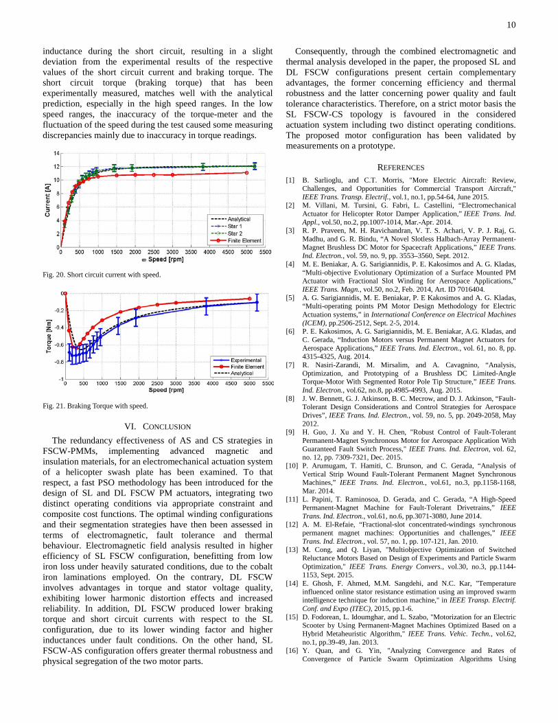
Fig. 13. AS and CS temperature variations across motor radial length, from rotor to stator, under both operating conditions. iron lamination type is M235-35A and the PM material is Neodymium NMX-34EH. The performance characteristics of the conventional magnetic materials employed are tabulated in Table VI. Initially, the electromagnetic field analysis is employed with inputs the nominal (J=5Α/mm2) and overload (J=8.5 A/mm2) current density, as presented in Table V for the SL-FSCW with the advanced magnetic materials. The magnetic field density distribution for the nominal and extreme electric load is illustrated in Fig. 14, where it can be observed that the motor exhibits lower saturation levels, due to the implementation of the M235-35A iron laminations. The lower flux density values exhibited at the stator laminations, in conjunction with the lower remanence of the PMs, results in lower torque capability, maximum power density (17%) and efficiency, compared to the respective design utilizing the advanced magnetic materials. As a result, PMM design utilizing conventional magnetic materials demands higher armature current, in order to meet torque specifications under normal and extreme operating condition. Thus, the thermal robustness of the resultant motor using conventional materials is quite limited, and high temperature values, above the limits specified in Table I, are taken place in the PMs and windings particularly under the extreme operation, as shown in Table VI. Moreover, an overall cost increase by approximately 50% is incurred for the prototype construction by using Vacoflux50 material, although such a construction cost comparison cannot extended to raw motor production.
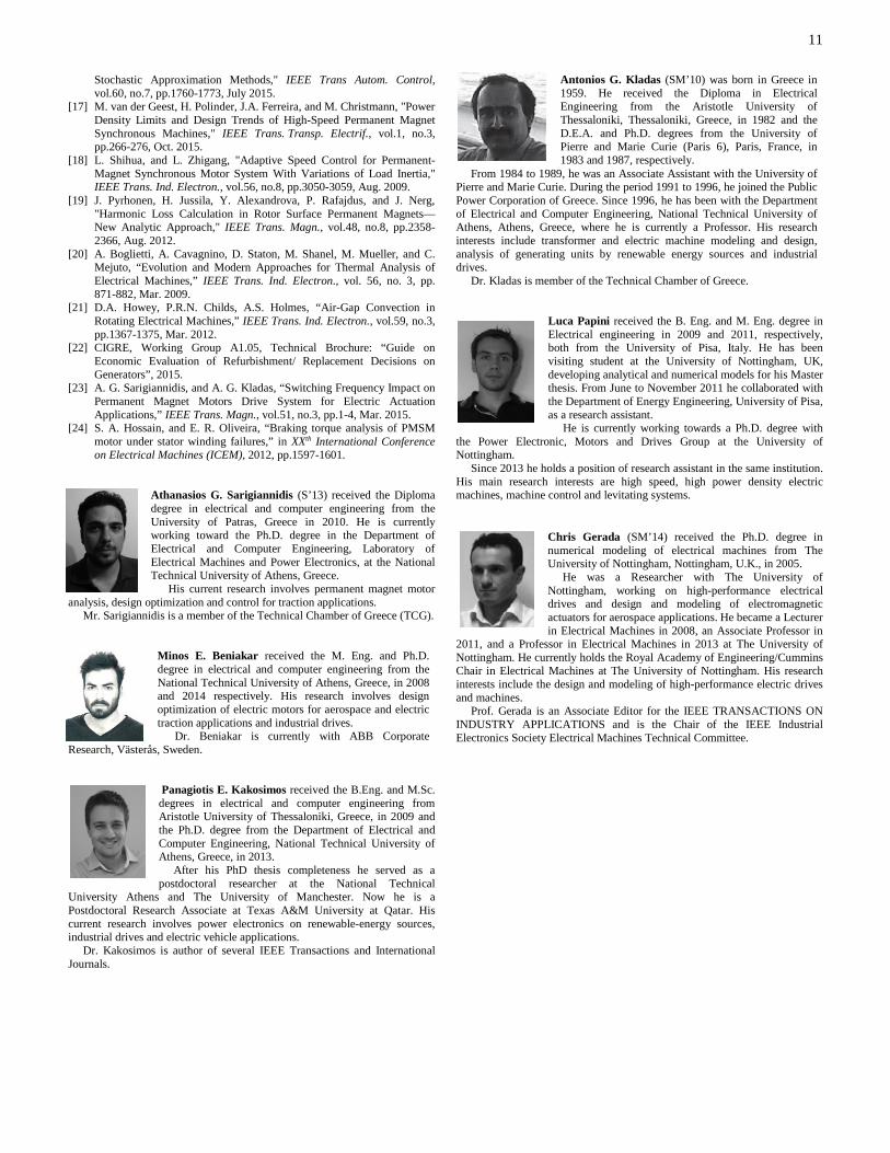
V. EXPERIMENTAL VALIDATION The optimized AS-SL FSCW actuator topology, which has
been favored from the preceded comparative analysis, has been validated by measurements on a manufactured prototype. For this purpose, a convenient experimental setup with a six phase inverter has been implemented. For constructional
Fig. 14. Magnetic flux density distribution of SL-FSCW for the nominal (left) and overload (right) armature current values.
TABLE VI SIMULATED SL FSCW ACTUATOR CHARACTERISTICS UTILIZING
CONVENTIONAL MAGNETIC MATERIALS.
purposes, the active part length has been slightly adopted to the existing hydraulic actuator space availability. The motor parts and the signal routing from the experimental setup overview are illustrated in Fig. 15. The switching frequency of PWM voltage is selected at 9kHz, due to its advantageous characteristics in terms of drive system efficiency and torque quality [23].
(a) (b)
(c)
Fig. 15. (a) PMM stator with FSCW. (b) PMM rotor. (c) Experimental setup configuration.
2.2
1.8
1.4
0
B (T)
0.6
1.0
Electric Loading type Nominal (500rpm)
Overload (6000rpm)
Tm (Nm) 3.36 5.85 Efficiency (%) 81.1 89.7
Armature current density (A/mm2) 5 8.5 Maximum temperature in PMs /
Windings (oC) 87 / 89 205 / 219
Maximum power density at extreme operation (kW/dm3) 5.03
Permanent Magnet (PM) Type NdFeB (NMX-34EH) Remanent flux (T) 1.10@60oC 0.97@180oC
Coercive force (MA/m) 1.58@60oC 0.57@180oC Iron laminations Type M235-35A
Core loss (W/kg) at 50 Hz - 1.8T 2.94 Core loss (W/kg) at 400Hz - 1.5T 41.2

9
Initially, the no load test is performed, and the simulated as well as the measured PMM three phase no load voltages at high speed are shown in Figs.16a and 16b, respectively. These figures illustrate the good agreement between simulated and measured EMF time variations.
(a) (b)
Fig. 16. No-load phase voltage at high speed (5200rpm). (a) simulated (b) measured. The measured mean torque with current under low speed operation is given in Fig. 17, highlighting the linearity of torque with loading current observed at the design stage. The saturation of the iron core can be noticed in the change of the slope when current reaches the value of 30 Amperes. However, this kind of electric loading corresponds to a high armature current density of approximately 10 A/mm2, which can be encountered at extreme operating conditions, for a short time duration, during certain maneuvers of the helicopter, or in case of a fault. Furthermore, the machine has been tested at different rotational speeds from 0 to the maximum operating speed and various loading currents. From the results shown in Fig. 18, the torque reduction observed at higher speeds for the same stator currents can mainly be attributed to eddy current losses in iron laminations, stator windings and PMs corresponding to the higher supply frequencies. It should also be noted that regardless to the fact that the frequency modulation ratio of PMM drive system is quite low for the extreme operation considered (mf=18) due to the high number of poles, the vector current control performs adequately and stably at this operating speed, presenting low harmonic distortion in armature current (THD< 5%), as shown in Figs. 19a and 19b, respectively. This is attributed mainly to the high filtering action by the winding reactance, due to the high speed value. The low THD current value provides reliable d-q axis Park transformations, with low ripple in reference values *
dv and *qv .
Fig. 17. Torque with Iq current: the winding structures have been energized separately (curve labeled as “Star 1” and “Star 2”) at 200rpm.
Fig. 18. Torque with Iq current at different operative speed with both winding structures energized.
(a)
(b)
Fig. 19. Experimental SPWM phase voltage and current of PMM with both winding structures energized at extreme operation (T=7Nm, n=5900rpm). In a next step, the short circuit test on the prototype is performed in order to validate the braking torque and the amplitude of the short circuit current that has been calculated at the design stage of the motor. The tests have been performed by short circuiting the three phases of each winding structure at the same time while the other star connected windings are kept in open circuit conditions. Phase currents and developed torque are measured and reported in Figs. 20 and 21, respectively. As expected, the peak of the short circuit currents are increasing at low speed ranges while the results are limited to a practically constant value due to the winding reactance, at the higher speed ranges. Very good agreement between the analytical prediction and the experimental results can be observed. The error in the current measurement is equally shown in this graph. The motor resistance and inductance that has been measured in the experimental test is included in the analytical equivalent circuit based model for the short circuit analysis [24]. The measured armature resistance considered in the analytical evaluation of the braking torque is equal to 115 mΩ. The FE model simulations are performed considering an ideal winding end zone part
10
inductance during the short circuit, resulting in a slight deviation from the experimental results of the respective values of the short circuit current and braking torque. The short circuit torque (braking torque) that has been experimentally measured, matches well with the analytical prediction, especially in the high speed ranges. In the low speed ranges, the inaccuracy of the torque-meter and the fluctuation of the speed during the test caused some measuring discrepancies mainly due to inaccuracy in torque readings.
Fig. 20. Short circuit current with speed.
Fig. 21. Braking Torque with speed.
VI. CONCLUSION The redundancy effectiveness of AS and CS strategies in FSCW-PMMs, implementing advanced magnetic and insulation materials, for an electromechanical actuation system of a helicopter swash plate has been examined. To that respect, a fast PSO methodology has been introduced for the design of SL and DL FSCW PM actuators, integrating two distinct operating conditions via appropriate constraint and composite cost functions. The optimal winding configurations and their segmentation strategies have then been assessed in terms of electromagnetic, fault tolerance and thermal behaviour. Electromagnetic field analysis resulted in higher efficiency of SL FSCW configuration, benefitting from low iron loss under heavily saturated conditions, due to the cobalt iron laminations employed. On the contrary, DL FSCW involves advantages in torque and stator voltage quality, exhibiting lower harmonic distortion effects and increased reliability. In addition, DL FSCW produced lower braking torque and short circuit currents with respect to the SL configuration, due to its lower winding factor and higher inductances under fault conditions. On the other hand, SL FSCW-AS configuration offers greater thermal robustness and physical segregation of the two motor parts.
Consequently, through the combined electromagnetic and thermal analysis developed in the paper, the proposed SL and DL FSCW configurations present certain complementary advantages, the former concerning efficiency and thermal robustness and the latter concerning power quality and fault tolerance characteristics. Therefore, on a strict motor basis the SL FSCW-CS topology is favoured in the considered actuation system including two distinct operating conditions. The proposed motor configuration has been validated by measurements on a prototype.
REFERENCES [1] B. Sarlioglu, and C.T. Morris, "More Electric Aircraft: Review,
Challenges, and Opportunities for Commercial Transport Aircraft," IEEE Trans. Transp. Electrif., vol.1, no.1, pp.54-64, June 2015.
[2] M. Villani, M. Tursini, G. Fabri, L. Castellini, “Electromechanical Actuator for Helicopter Rotor Damper Application,” IEEE Trans. Ind. Appl., vol.50, no.2, pp.1007-1014, Mar.-Apr. 2014.
[3] R. P. Praveen, M. H. Ravichandran, V. T. S. Achari, V. P. J. Raj, G. Madhu, and G. R. Bindu, “A Novel Slotless Halbach-Array Permanent-Magnet Brushless DC Motor for Spacecraft Applications,” IEEE Trans. Ind. Electron., vol. 59, no. 9, pp. 3553–3560, Sept. 2012.
[4] M. E. Beniakar, A. G. Sarigiannidis, P. E. Kakosimos and A. G. Kladas, “Multi-objective Evolutionary Optimization of a Surface Mounted PM Actuator with Fractional Slot Winding for Aerospace Applications,” IEEE Trans. Magn., vol.50, no.2, Feb. 2014, Art. ID 7016404.
[5] A. G. Sarigiannidis, M. E. Beniakar, P. E Kakosimos and A. G. Kladas, “Multi-operating points PM Motor Design Methodology for Electric Actuation systems,” in International Conference on Electrical Machines (ICEM), pp.2506-2512, Sept. 2-5, 2014.
[6] P. E. Kakosimos, A. G. Sarigiannidis, M. E. Beniakar, A.G. Kladas, and C. Gerada, “Induction Motors versus Permanent Magnet Actuators for Aerospace Applications,” IEEE Trans. Ind. Electron., vol. 61, no. 8, pp. 4315-4325, Aug. 2014.
[7] R. Nasiri-Zarandi, M. Mirsalim, and A. Cavagnino, “Analysis, Optimization, and Prototyping of a Brushless DC Limited-Angle Torque-Motor With Segmented Rotor Pole Tip Structure,” IEEE Trans. Ind. Electron., vol.62, no.8, pp.4985-4993, Aug. 2015.
[8] J. W. Bennett, G. J. Atkinson, B. C. Mecrow, and D. J. Atkinson, “Fault-Tolerant Design Considerations and Control Strategies for Aerospace Drives”, IEEE Trans. Ind. Electron., vol. 59, no. 5, pp. 2049-2058, May 2012.
[9] H. Guo, J. Xu and Y. H. Chen, "Robust Control of Fault-Tolerant Permanent-Magnet Synchronous Motor for Aerospace Application With Guaranteed Fault Switch Process," IEEE Trans. Ind. Electron, vol. 62, no. 12, pp. 7309-7321, Dec. 2015.
[10] P. Arumugam, T. Hamiti, C. Brunson, and C. Gerada, “Analysis of Vertical Strip Wound Fault-Tolerant Permanent Magnet Synchronous Machines,” IEEE Trans. Ind. Electron., vol.61, no.3, pp.1158-1168, Mar. 2014.
[11] L. Papini, T. Raminosoa, D. Gerada, and C. Gerada, “A High-Speed Permanent-Magnet Machine for Fault-Tolerant Drivetrains,” IEEE Trans. Ind. Electron., vol.61, no.6, pp.3071-3080, June 2014.
[12] A. M. El-Refaie, “Fractional-slot concentrated-windings synchronous permanent magnet machines: Opportunities and challenges,” IEEE Trans. Ind. Electron., vol. 57, no. 1, pp. 107-121, Jan. 2010.
[13] M. Cong, and Q. Liyan, "Multiobjective Optimization of Switched Reluctance Motors Based on Design of Experiments and Particle Swarm Optimization," IEEE Trans. Energy Convers., vol.30, no.3, pp.1144-1153, Sept. 2015.
[14] E. Ghosh, F. Ahmed, M.M. Sangdehi, and N.C. Kar, "Temperature influenced online stator resistance estimation using an improved swarm intelligence technique for induction machine," in IEEE Transp. Electrif. Conf. and Expo (ITEC), 2015, pp.1-6.
[15] D. Fodorean, L. Idoumghar, and L. Szabo, "Motorization for an Electric Scooter by Using Permanent-Magnet Machines Optimized Based on a Hybrid Metaheuristic Algorithm," IEEE Trans. Vehic. Techn., vol.62, no.1, pp.39-49, Jan. 2013.
[16] Y. Quan, and G. Yin, "Analyzing Convergence and Rates of Convergence of Particle Swarm Optimization Algorithms Using
11
Stochastic Approximation Methods," IEEE Trans Autom. Control, vol.60, no.7, pp.1760-1773, July 2015.
[17] M. van der Geest, H. Polinder, J.A. Ferreira, and M. Christmann, "Power Density Limits and Design Trends of High-Speed Permanent Magnet Synchronous Machines," IEEE Trans. Transp. Electrif., vol.1, no.3, pp.266-276, Oct. 2015.
[18] L. Shihua, and L. Zhigang, "Adaptive Speed Control for Permanent-Magnet Synchronous Motor System With Variations of Load Inertia," IEEE Trans. Ind. Electron., vol.56, no.8, pp.3050-3059, Aug. 2009.
[19] J. Pyrhonen, H. Jussila, Y. Alexandrova, P. Rafajdus, and J. Nerg, "Harmonic Loss Calculation in Rotor Surface Permanent Magnets—New Analytic Approach," IEEE Trans. Magn., vol.48, no.8, pp.2358-2366, Aug. 2012.
[20] A. Boglietti, A. Cavagnino, D. Staton, M. Shanel, M. Mueller, and C. Mejuto, “Evolution and Modern Approaches for Thermal Analysis of Electrical Machines,” IEEE Trans. Ind. Electron., vol. 56, no. 3, pp. 871-882, Mar. 2009.
[21] D.A. Howey, P.R.N. Childs, A.S. Holmes, “Air-Gap Convection in Rotating Electrical Machines,” IEEE Trans. Ind. Electron., vol.59, no.3, pp.1367-1375, Mar. 2012.
[22] CIGRE, Working Group A1.05, Technical Brochure: “Guide on Economic Evaluation of Refurbishment/ Replacement Decisions on Generators”, 2015.
[23] A. G. Sarigiannidis, and A. G. Kladas, “Switching Frequency Impact on Permanent Magnet Motors Drive System for Electric Actuation Applications,” IEEE Trans. Magn., vol.51, no.3, pp.1-4, Mar. 2015.
[24] S. A. Hossain, and E. R. Oliveira, “Braking torque analysis of PMSM motor under stator winding failures,” in XXth International Conference on Electrical Machines (ICEM), 2012, pp.1597-1601.
Athanasios G. Sarigiannidis (S’13) received the Diploma degree in electrical and computer engineering from the University of Patras, Greece in 2010. He is currently working toward the Ph.D. degree in the Department of Electrical and Computer Engineering, Laboratory of Electrical Machines and Power Electronics, at the National Technical University of Athens, Greece.
His current research involves permanent magnet motor analysis, design optimization and control for traction applications.
Mr. Sarigiannidis is a member of the Technical Chamber of Greece (TCG).
Minos E. Beniakar received the M. Eng. and Ph.D. degree in electrical and computer engineering from the National Technical University of Athens, Greece, in 2008 and 2014 respectively. His research involves design optimization of electric motors for aerospace and electric traction applications and industrial drives.
Dr. Beniakar is currently with ABB Corporate Research, Västerås, Sweden.
Panagiotis E. Kakosimos received the B.Eng. and M.Sc. degrees in electrical and computer engineering from Aristotle University of Thessaloniki, Greece, in 2009 and the Ph.D. degree from the Department of Electrical and Computer Engineering, National Technical University of Athens, Greece, in 2013. After his PhD thesis completeness he served as a postdoctoral researcher at the National Technical
University Athens and The University of Manchester. Now he is a Postdoctoral Research Associate at Texas A&M University at Qatar. His current research involves power electronics on renewable-energy sources, industrial drives and electric vehicle applications. Dr. Kakosimos is author of several IEEE Transactions and International Journals.
Antonios G. Kladas (SM’10) was born in Greece in 1959. He received the Diploma in Electrical Engineering from the Aristotle University of Thessaloniki, Thessaloniki, Greece, in 1982 and the D.E.A. and Ph.D. degrees from the University of Pierre and Marie Curie (Paris 6), Paris, France, in 1983 and 1987, respectively.
From 1984 to 1989, he was an Associate Assistant with the University of Pierre and Marie Curie. During the period 1991 to 1996, he joined the Public Power Corporation of Greece. Since 1996, he has been with the Department of Electrical and Computer Engineering, National Technical University of Athens, Athens, Greece, where he is currently a Professor. His research interests include transformer and electric machine modeling and design, analysis of generating units by renewable energy sources and industrial drives.
Dr. Kladas is member of the Technical Chamber of Greece.
Luca Papini received the B. Eng. and M. Eng. degree in Electrical engineering in 2009 and 2011, respectively, both from the University of Pisa, Italy. He has been visiting student at the University of Nottingham, UK, developing analytical and numerical models for his Master thesis. From June to November 2011 he collaborated with the Department of Energy Engineering, University of Pisa, as a research assistant. He is currently working towards a Ph.D. degree with
the Power Electronic, Motors and Drives Group at the University of Nottingham. Since 2013 he holds a position of research assistant in the same institution. His main research interests are high speed, high power density electric machines, machine control and levitating systems.
Chris Gerada (SM’14) received the Ph.D. degree in numerical modeling of electrical machines from The University of Nottingham, Nottingham, U.K., in 2005. He was a Researcher with The University of Nottingham, working on high-performance electrical drives and design and modeling of electromagnetic actuators for aerospace applications. He became a Lecturer in Electrical Machines in 2008, an Associate Professor in
2011, and a Professor in Electrical Machines in 2013 at The University of Nottingham. He currently holds the Royal Academy of Engineering/Cummins Chair in Electrical Machines at The University of Nottingham. His research interests include the design and modeling of high-performance electric drives and machines. Prof. Gerada is an Associate Editor for the IEEE TRANSACTIONS ON INDUSTRY APPLICATIONS and is the Chair of the IEEE Industrial Electronics Society Electrical Machines Technical Committee.