Embed Size (px)
Citation preview
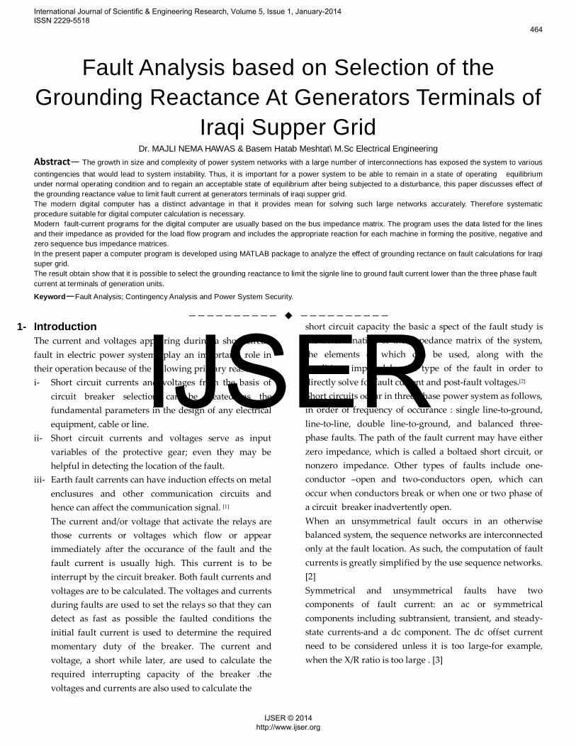
Fault Analysis based on Selection of the Grounding Reactance At Generators Terminals of
Iraqi Supper Grid Dr. MAJLI NEMA HAWAS & Basem Hatab Meshtat\ M.Sc Electrical Engineering
Abstract— The growth in size and complexity of power system networks with a large number of interconnections has exposed the system to various contingencies that would lead to system instability. Thus, it is important for a power system to be able to remain in a state of operating equilibrium under normal operating condition and to regain an acceptable state of equilibrium after being subjected to a disturbance, this paper discusses effect of the grounding reactance value to limit fault current at generators terminals of iraqi supper grid. The modern digital computer has a distinct advantage in that it provides mean for solving such large networks accurately. Therefore systematic procedure suitable for digital computer calculation is necessary. Modern fault-current programs for the digital computer are usually based on the bus impedance matrix. The program uses the data listed for the lines and their impedance as provided for the load flow program and includes the appropriate reaction for each machine in forming the positive, negative and zero sequence bus impedance matrices. In the present paper a computer program is developed using MATLAB package to analyze the effect of grounding rectance on fault calculations for Iraqi super grid. The result obtain show that it is possible to select the grounding reactance to limit the signle line to ground fault current lower than the three phase fault current at terminals of generation units. Keyword—Fault Analysis; Contingency Analysis and Power System Security.
—————————— ——————————1- Introduction
The current and voltages appearing during a short circuit fault in electric power systems play an important role in their operation because of the following primary reasons : i- Short circuit currents and voltages from the basis of
circuit breaker selection can be treated as the fundamental parameters in the design of any electrical equipment, cable or line.
ii- Short circuit currents and voltages serve as input variables of the protective gear; even they may be helpful in detecting the location of the fault.
iii- Earth fault carrents can have induction effects on metal enclusures and other communication circuits and hence can affect the communication signal. P
[1] The current and/or voltage that activate the relays are those currents or voltages which flow or appear immediately after the occurance of the fault and the fault current is usually high. This current is to be interrupt by the circuit breaker. Both fault currents and voltages are to be calculated. The voltages and currents during faults are used to set the relays so that they can detect as fast as possible the faulted conditions the initial fault current is used to determine the required momentary duty of the breaker. The current and voltage, a short while later, are used to calculate the required interrupting capacity of the breaker .the voltages and currents are also used to calculate the
short circuit capacity the basic a spect of the fault study is the determination of the impedance matrix of the system, the elements of which can be used, along with the conditions imposed by the type of the fault in order to directly solve for fault current and post-fault voltages.P
[2] Short circuits occur in three-phase power system as follows, in order of frequency of occurance : single line-to-ground, line-to-line, double line-to-ground, and balanced three-phase faults. The path of the fault current may have either zero impedance, which is called a boltaed short circuit, or nonzero impedance. Other types of faults include one-conductor –open and two-conductors open, which can occur when conductors break or when one or two phase of a circuit breaker inadvertently open. When an unsymmetrical fault occurs in an otherwise balanced system, the sequence networks are interconnected only at the fault location. As such, the computation of fault currents is greatly simplified by the use sequence networks. [2] Symmetrical and unsymmetrical faults have two components of fault current: an ac or symmetrical components including subtransient, transient, and steady-state currents-and a dc component. The dc offset current need to be considered unless it is too large-for example, when the X/R ratio is too large . [3]
International Journal of Scientific & Engineering Research, Volume 5, Issue 1, January-2014 ISSN 2229-5518
464
IJSER © 2014 http://www.ijser.org
IJSER

2- System modeling : The zero-, positive - , and negative –sequence networks of system components-generators, motors, transformers and transmission lines can be used to construct transmmion line can be used to construct system zero-, positive-, an d negative-sequence networks we make the following assumptions : [4]
i. The power system operates under balanced steady-state conditions before the fault occurs. Thus the zero-, positive- , and negative-sequance networks are uncoupled before the fault occurs. During unsymmetrical faults they are interconnected only at the fault location.
ii. Prefault load current is neglected, because of this, the positive sequence internal voltages of all machine are equal to the prefault voltage vf. Therefore, the prefault voltage at each bus in the positive-sequence network equals vf.
iii. Transformer winding resistances and shunt admiances are neglected.
iv. Transmission-line series resistance and shunt admittances are neglected.
v. Synchronous machines armature resistance saliency, and saturation are neglected.
vi. All nonrotating impedance loads are neglected. vii. Induction motors are either neglected (especially for
motors rated 50 hp or less) or represented in the same manner as synchronous machine.
3- Determination of symmetrical fault current methods : 3.1 determination of symmetrical fault current using zbus inversion: The easiest way to find symmetrical fault current bus in a multi-bus power system is olotained directly from [zbus] (bus impedance matrix) provided [zbus] is formed by [ybus] (bus admittance matrix) inversion. For large system this approach becomes unacceptable because of the need of inverting a very largematrix; also for any change in the network, the full [ybus] is to be rebuilt and again the inversion technique needs to be applied.[4,5] 3.2 determination of fault current by formulating the impedance matrix using network theory:
For a passive n-port liner network, from circuit theory concepts, [𝑉] = [𝑍][𝐼] 1
The general entry in the [𝑍𝑏𝑢𝑠] = [𝑍] can then be calculated from the following equation,
𝑍𝑖𝑘 =𝑉𝑖𝐼𝑘� 𝐼1 = 𝐼2 = ⋯ = 𝐼𝑛 = 0 ; 𝐼𝑘 ≠ 0 (2)
This method presents great difficulty in solving for 𝑉𝑖 and hence not widly accepted for multi-bus system. On the
other hand, we prefer [𝑍𝑏𝑢𝑠] building algorithm as this technique is a programmable step-by-step method and any modification in the network dose not require a complete
rebuilding of [𝑍𝑏𝑢𝑠]. [4,5] 4- Generalized fault analysis using 𝒁𝒃𝒖𝒔 building algorithm.
The process of 𝑍𝑏𝑢𝑠 building can be directly applied to develop sequence networks of linear passive networks. Let the fault be applied to the i-th bus bus of the n-bus power system, the reference bus being the r-th bus. The generalized representation of the sequence network where we indicate all the bus currents except i-th bus current are zero (since bus- is terminated by a fault,
sequence currents 𝐼𝑖0, 𝐼𝑖1, 𝑎𝑛𝑑 𝐼𝑖2 would flow). No other sequence model except positive sequence network does have source (E). [4,6]
5- Unbalanced Fault Analysis Using Bus Impedance Matrix When the network is balanced, the symmetrical components impedances are diagonal, so that it is possible
to calculate 𝑍𝑏𝑢𝑠separately for zero-, positive-, and negative-sequence networks. also, for a fault at bus k, the diagonal element in the k axis of the bus impedance matrix
𝑍𝑏𝑢𝑠 in the Thevenin’s impedance to the point of fault. In order to obtain a solution for the unbalanced faults, the bus impedance matrix for each sequence network is obtained
separately, then the sequence impedance 𝑍𝑘𝑘0 , 𝑍𝑘𝑘1 , 𝑍𝑘𝑘2 are connected together in Figures (1,2,3). The fault formulas for various unbalanced fault are summarized below. In writing the symmetrical components of voltage and currents, the subscript a is left out and the symmetrical components are understood to refer to phase a.[7,8]
Figure 1 Sequence network connection for line-to-ground fault.
International Journal of Scientific & Engineering Research, Volume 5, Issue 1, January-2014 ISSN 2229-5518
465
IJSER © 2014 http://www.ijser.org
IJSER

Figure 3 Sequence network connection for double line-to-ground fault
Figure 2 Sequence network connection for line-to-line fault 5.1- SINGLE LINE-TO-GROUND FAULT USING 𝒁𝒃𝒖𝒔 [8,9]
The line-to-ground fault requires that positive-, negative-, and zero-sequence networks for phase a be placed in series as shown in Fig. (1) in order to compute the zero-sequence fault current. Thus, in general, for a fault at bus k, the symmetrical components of fault current is 𝐼𝑘0 = 𝐼𝑘1 = 𝐼𝑘2 = 𝑉𝑘0 �𝑍𝑘𝑘1 + 𝑍𝑘𝑘2 + 𝑍𝑘𝑘0 + 3𝑍𝑓�� (3) The fault current is 𝐼𝑘 = 3𝐼𝑘0 (4) The fault phase current is 𝐼𝑘𝑎𝑏𝑐 = 𝐴𝐼𝑘012 (5) 5.2- LINE-TO-LINE FAULT USING 𝒁𝒃𝒖𝒔 P
[8,9]
The phase a sequence network of Figure (2) is applicable here, where the positive- and negative-sequence networks are placed in opposition. The symmetrical components of the fault current as given. 𝐼𝑘0 = 0 (6) 𝐼𝑘1 = −𝐼𝑘2 = 𝑉𝑘0 �𝑍𝑘𝑘1 + 𝑍𝑘𝑘2 + 𝑍𝑓�� (7) 5.3- DOUBLE LINE-TO-GROUND FAULT USING 𝒁𝒃𝒖𝒔 P
[8,9]
The phase a sequence network of Figure (3) is applicable here, where the positive-sequence impedance is placed in series with the parallel combination of the negative- and zero-sequence
networks. the symmetrical components of the fault current as given
𝐼𝑘1 = 𝑉𝑘0 �𝑍𝑘𝑘1 +𝑍𝑘𝑘2 (𝑍𝑘𝑘0 + 3𝑍𝑓)𝑍𝑘𝑘1 + 𝑍𝑘𝑘2 + 3𝑍𝑓
�� (8)
𝐼𝑘2 = �𝑉𝑘0 + 𝑍𝑘𝑘1 𝐼𝑘1� �𝑍𝑘𝑘2 + 3𝑍𝑓�� (9) 𝐼𝑘0 = �𝑉𝑘𝑉𝑘0 + 𝑍𝑘𝑘1 𝐼𝑘1� �𝑍𝑘𝑘0 + 3𝑍𝑓�� (10) The phase current are obtained from (5) and the fault current is 𝐼𝑘𝑓 = 𝐼𝑘𝑏 + 𝐼𝑘𝑐 (11)
5-4 open conductor faults : [10,11] The sequence currents and voltages are suitably connected to represent the complete sequence network depending on the type of fault, i.e wether a single conductor fault or two conductor fault. 5.4.1-single conductor open fault :
For one conductor open (Fig (4))
𝑉𝑦𝑦′ = 𝑉𝑏𝑏′ = 0 (12)
𝐼𝑟 = 0 (13)
In terms of symmetrical components, we have 𝑉𝑟𝑟′ 1 = 𝑉𝑟𝑟′
2 = 𝑉𝑟𝑟′ 0 = 1
3 𝑉𝑟𝑟′ (14)
𝐼𝑟1 + 𝐼𝑟2 + 𝐼𝑟0 = 0 (15) Thus, the sequence network is clearly a parallel connected networks show in fig. ( 4.b)
Fig (41 ) connection of sequence diagram of one conductor open fault.
(a)
(b)
International Journal of Scientific & Engineering Research, Volume 5, Issue 1, January-2014 ISSN 2229-5518
466
IJSER © 2014 http://www.ijser.org
IJSER

5-4.2 Two conductor open fault : [10,11]
We assume conductor y and b are open obviously, 𝑉𝑟𝑟′0 =
0 & 𝐼𝑦 = 𝐼𝑏 = 0
In term of symmetrical components, we have
𝑉𝑟𝑟′ 1 = 𝑉𝑟𝑟′
2 = 𝑉𝑟𝑟′ 0 = 0 (16)
𝐼𝑟1 + 𝐼𝑟2 + 𝐼𝑟0 = 13
𝐼𝑟 (17)
These equations suggest that the connection diagram is a series connected sequence network as shown in fig. ( 5.b )
6- Effect of neutral grounding on fault current: [12,13]
For a solid L.G. fault, 𝑍𝑓 become zero. Hence the fault current
at phase R can be obtained as
𝐼𝑅 = 3 � 𝐸 𝑍𝑖𝑖0+ 𝑍𝑖𝑖
1+ 𝑍𝑖𝑖2� (18)
𝐼0 = 𝐼1 = 𝐼2 = 13
𝐼𝑓 (19)
Assuming the resistance part of the impedance component to be negligible and assuming the postion and negative sequence reactance equal, we can further modify the above equation as
𝐼𝑅 = 3𝐸2𝑋𝑖𝑖
1+ 𝑋𝑖𝑖0 (20)
On the other hand, for a solid three phase fault, we have
𝐼𝑅 = 𝐸𝑋𝑖𝑖1 (21)
Comparing equation (20) & (21), we find that for a generator with equal positive and negative sequence reactances and neutral solidly grounded, we have the single line to ground fault is more severe than the three phase fault while the zero
sequence reactance is of low value. Howver, if 𝑋𝑖𝑖0 is much
higher than 𝑋𝑖𝑖1 , there is a possibility that the three-phase current is higher in magnitude than the line to ground fault curent. In practical context, we find that if fault occurs at the
generator terminals, due to lower value of 𝑋𝑖𝑖0 , 𝐼𝑅(𝐿−𝑔) > 𝐼𝑅(3𝐿)
while for a fault in the tramsmission line ,
𝐼𝑅(3𝐿) > 𝐼𝑅(𝐿−𝑔) (22)
If we want to make the fault curent due to L_G fault less tha three-phase fault current at generator terminals using a grounding reactance (𝑋𝑛) at the neutral, we can write
3𝐸2𝑋𝑖𝑖
1+ 𝑋𝑖𝑖0+ 3𝑋𝑛
< 𝐸𝑋𝑖𝑖1 (23)
Or
2𝑋𝑖𝑖1 + 𝑋𝑖𝑖0 + 3𝑋𝑛 > 3𝑋𝑖𝑖1 (24)
∴ 𝑋𝑛 > �𝑋𝑖𝑖1− 𝑋𝑖𝑖
0�3
(25)
Thus, it is possible to select the grounding reactance ( 𝑋𝑛 ) to limit the L-G fault current lower than the L-L-L fault current.
Fig.(5 ) connection of sequence diagram of two conductor open fault.
R
Y
B
(a)
(b)
International Journal of Scientific & Engineering Research, Volume 5, Issue 1, January-2014 ISSN 2229-5518
467
IJSER © 2014 http://www.ijser.org
IJSER

7- BUS VOLTAGES AND LINE CURRENTS DURING FAULT. [10]
The symmetrical components of the ith bus voltages during fault are obtained
𝑉𝑖0𝑓 = 0 − 𝑍𝑖𝑘0 𝐼𝑘0 (26)
𝑉𝑖1𝑓 = 𝑉𝑖1 − 𝑍𝑖𝑘1 𝐼𝑘1 (27)
𝑉𝑖2𝑓 = 0 − 𝑍𝑖𝑘2 𝐼𝑘2 (28)
The phase voltage during fault are
𝑉𝑖𝑎𝑏𝑐 = 𝐴𝑉1012 (29) The symmetric components of fault current in line i to j is given by
𝐼𝑖𝑗0 = �𝑉𝑖0𝑓 − 𝑉𝑗
0𝑓� 𝑍𝑖𝑗0� (30)
𝐼𝑖𝑗1 = �𝑉𝑖1𝑓 − 𝑉𝑗
1𝑓� 𝑍𝑖𝑗1� (31)
𝐼𝑖𝑗2 = �𝑉𝑖2𝑓 − 𝑉𝑗
2𝑓� 𝑍𝑖𝑗2� (32)
Having obtained the symmetrical components of line current, the phase fault current in line i to j is 𝐼𝑖𝑗𝑎𝑏𝑐 = 𝐴𝐼𝑖𝑗012 (33)
7.1 Determine of line current during fault condition :
The current flowing through any line during the faulted condition can be obtained once the bus voltages at both the ends of the line are known :
𝐼𝑖𝑘𝑠 = 𝑉𝑖𝑠− 𝑉𝑘
𝑠
𝑍𝑖𝑘𝑠 (34)
8. Test system data.
8.1 First System data
The first system consists of 11 bus and 14 Transmission lines.
8.2 Second system data
The second system consist of 24 Bus and 35 Transmission lines. Fig.(6) shows a configuration of this system.
Figure (6) Iraqi super grid configuration.[15]
Table 1 : Classification of Iraq super Grid buses.
Bus No.
Bus Name
Bus Type
Bus No.
Bus Name
Bus Type
Bus No.
Bus Name
Bus Type
1 MMDH Gen. 9 BGE4 Load 17 MUSP Gen. 2 MSL4 Load 10 QDSG Gen. 18 BAB4 Load 3 BAJP Gen. 11 BGN4 Load 19 KDS4 Load 4 BAJG Gen. 12 BGW4 Load 20 NSRP Gen. 5 KRK4 Gen. 13 BGS4 Load 21 KAZG Gen. 6 QIM4 Load 14 AMN4 Load 22 AMR4 Load 7 HDTH Gen. 15 KUT4 Load 23 HRTP Gen. 8 DAL4 Load 16 MUSG Gen. 24 BGC4 Gen.
2 5 9
63 ACSS
184 ACSS
128 ACSS
150 AAAC
229 AAAC
223 AAAC
1 AAAC
20
19
21
23
22
15
6
7
18
11
14 24
17
16
13
10
1
4 3 8
12
83 AAAC 187 AAAC
40 AAAC
13 AAAC
7
43 AAAC
20 AAAC
38 AAAC
35.5 ACSD 102 ACSD
176.9 AAAC
290 AAAC 120 AAAC 60 AAAC
202.7 AAAC
141.9 AAAC
199.4 AAAC
58.2 AAAC 28
AAAC
44 AAAC
53.5 ACSD
48 ACSD 5.5 ACSD
230 AAAC 233 AAAC
221 AAAC
13.4 AAAC
114.4 AAAC + 42 ACSD
International Journal of Scientific & Engineering Research, Volume 5, Issue 1, January-2014 ISSN 2229-5518
468
IJSER © 2014 http://www.ijser.org
IJSER

9- Flowchart for short circuit studies.
10- Result and discussion: The result show that for a generator with equal positive and negative neactances and neutral solidly grounded, the single line to ground fault is greater than the three phase fault while the zero sequence reactance is of low value. As shown at tables 2,3,5 & 6, because the fault occurs at the generator terminals and due to lower value of zero sequence reactance and neutral solidly grounded the fault current at single line to ground fault more than three-phase fault current. And as shown at tables 4&7 when we use a grounding reactance at the neutral the line to ground fault current become lower than the 3-phase fault current. Figure 8 & 10 show the simulation of symmetrical faulted current at first system and second system. Figure 9 & 11 show the simulation of unsymmetrical faulted current at first system and second system.
Table (4) fault current at 𝑋𝑛 = 23
(𝑋1 − 𝑋0 )
Faulted bus Gen.
Faulted current at
Three phase fault
L-L fault
L-G fault
D-L-G fault
1 First 7.35 6.36 4.91 3.68
10 Second 8.45 7.32 7.38 6.55
11 Third 5.76 4.99 3.96 2.96
Figure (7) flow chart for short circuit studies
Compute 1- Fault current 2- Post-fault bus
voltages 3- Line currents after
fault.
Start
Stop
Read, NB, 𝑍𝑏𝑢𝑠0 , 𝑍𝑏𝑢𝑠1 , 𝑍𝑏𝑢𝑠2 , NL , Nf, NT, Z0, Z1, Z2,NFB
Compute 1- Fault current 2- Post-fault bus
voltages 3- Line currents after
fault.
Compute 1. Fault current 2. Post-fault bus
voltages 3. Line currents after
fault.
Compute 1- Fault current 2- Post-fault bus
voltages 3- Line currents after
fault.
Is this a line to line fault?
Is this solid a single phase open fault?
Compute 1. Fault current 2. Post-fault bus
voltages 3. Line currents after
fault.
Compute 1- Fault current 2- Post-fault bus
voltages 3- Line currents after
fault.
yes
Is this a solid double line to ground fault
Is this solid a two phase open fault?
no
yes
no
no
Is this a solid three phase to ground fault?
no
no
Is this a solid single phase to ground fault?
yes
yes
yes
yes
Faulted bus Gen.
Faulted current at Three
phase fault L-L fault
L-G fault
D-L-G fault
1 First 7.35 6.36 9.03 8.65 10 Second 8.45 7.32 10.93 10.64
11 Third 5.76 4.99 7.03 6.72
Table (2) fault current at xn = 0
Table (3) fault current at 𝑋𝑛 = 16
(𝑋1 − 𝑋0 )
Faulted
bus Gen.
Faulted current at Three phase fault
L-L fault
L-G fault
D-L-G fault
1 First 7.35 6.36 7.48 4.2 10 Second 8.45 7.32 9.58 9.18 11 Third 5.76 4.99 5.87 2.8
International Journal of Scientific & Engineering Research, Volume 5, Issue 1, January-2014 ISSN 2229-5518
469
IJSER © 2014 http://www.ijser.org
IJSER
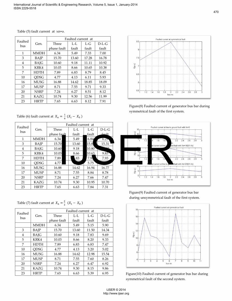
Figure(8) Faulted current of generator bus bar during symmetrical fault of the first system.
Figure(9) Faulted current of generator bus bar during unsymmetrical fault of the first system.
Figure(10) Faulted current of generator bus bar during symmetrical fault of the second system.
Table (6) fault current at 𝑋𝑛 = 16
(𝑋1 − 𝑋0 )
Table (7) fault current at 𝑋𝑛 = 23
(𝑋1 − 𝑋0 )
Table (5) fault current at xn=o.
Faulted bus Gen.
Faulted current at Three
phase fault L-L fault
L-G fault
D-L-G fault
1 MMDH 6.34 5.49 7.33 7.00 3 BAJP 15.70 13.60 17.28 16.78 4 BAJG 10.60 9.18 11.11 10.92 5 KRK4 10.03 8.66 10.65 10.38 7 HDTH 7.89 6.83 8.79 8.45 10 QDSG 4.77 4.13 6.11 5.93 16 MUSG 16.88 14.62 18.85 18.09 17 MUSP 8.71 7.55 9.71 9.33 20 NSRP 7.24 6.27 8.51 8.12 21 KAZG 10.74 9.30 12.56 11.99 23 HRTP 7.65 6.63 8.12 7.91
Faulted bus Gen.
Faulted current at Three
phase fault L-L fault
L-G fault
D-L-G fault
1 MMDH 6.34 5.49 6.84 6.29 3 BAJP 15.70 13.60 15.83 15.31 4 BAJG 10.60 9.18 10.80 10.17 5 KRK4 10.03 8.66 10.63 9.83 7 HDTH 7.89 6.83 7.97 7.93 10 QDSG 4.77 4.13 5.75 5.50 16 MUSG 16.88 14.62 16.94 16.77 17 MUSP 8.71 7.55 8.84 8.78 20 NSRP 7.24 6.27 7.66 7.47 21 KAZG 10.74 9.30 10.95 10.70 23 HRTP 7.65 6.63 7.84 7.31
Faulted bus Gen.
Faulted current at Three
phase fault L-L fault
L-G fault
D-L-G fault
MMDH 6.34 5.49 5.15 5.90 3 BAJP 15.70 13.60 11.50 14.34 4 BAJG 10.60 9.18 7.83 9.69 5 KRK4 10.03 8.66 8.20 9.33 7 HDTH 7.89 6.83 6.83 7.47 10 QDSG 4.77 4.13 3.20 5.02 16 MUSG 16.88 14.62 12.98 15.54 17 MUSP 8.71 7.55 7.60 8.26 20 NSRP 7.24 6.27 6.47 6.92 21 KAZG 10.74 9.30 8.15 9.86 23 HRTP 7.65 6.63 5.39 6.95
International Journal of Scientific & Engineering Research, Volume 5, Issue 1, January-2014 ISSN 2229-5518
470
IJSER © 2014 http://www.ijser.org
IJSER

11- Conclusion: A short circuit computer program may be utilized in power
system design to select, set, and coordinate protective equipment such as circuit breaker, fuses, relays, and instrument transformer. For each terminal of the eleven generators select a suitable circuit breaker. For each breaker that you select should have arated short circuit current larger than the maximum fault current for any type of fault at the bus where the breaker is located. This conservative practice of selecting a breaker to interrupt the entive fault current, not just the contribution to the fault current through the breaker, allows for future increase in fault current since higher-rated circuit breaker cost more, you should select the circuit breaker with the lowest rating that satisfies.the design constraint.
REFRENCES
1- A.R. Bergen and V.vittal, “Power System Analysis”, 2nd
ed., prentice Hall, 2000. 2- P.M Anderrson, “Analysis of Faulted Power System”, Ames:
Iowa state university Press, 1973. 3- P. kundar, “Power System Stability and control” ,
McGraw-Hill, 1994. 4- A. Chakrobarti & S. Halder, “Power System Analysis
Operation and Control”, 3rd ed., PHI Learning Private Limited, New Delhi, 2011.
5- J.D. Glover, M. S. SARMA & T. J. overbye “Power System Analysis and Design) 4th ed., Thomson learning, United States of America, 2008.
6- B. R. Gupta, “Power System Analysis Design”, S. chand, 2008.
7- H. saadat, “Power System Analysis” In. ed (New York: WCB/McGraw-hill, 1999).
8- D.P. Kothari & I.J. Nagrath, “Modern Power System Analysis” 4th ed., Tata McGraw-Hill, 2009.
9- A.R. Bergan and V. Vittal, “Power System Analysis”, 2nd ed. (Upper Saddle River, NJ: Prentice Hall, 2000).
10- S.A. Soman, and S. Pandit, “Computational Methods For Large Sparse Power Systems Analysis” KAP, Boston, 2002.
11- J.J. Grainger & W.D. Stevenson, Jr., Elements of Power System Analysis, 4th ed. (New York: McGraw-hill, 2007).
12- A.R. Bergen, “Power System Analysis”, Englewood cliffs, NJ: Prentic-Hall, 1986.
13- Arthur R. Bergen, “Power System Analysis Prentie-Hall Inc., 1985.
14- E.W. Kimbark, “Power System Stability : Elements of Stability Calulation” Vol.1, IEEE press power system Engineering series, 1995.
15- Republic of Iraqi / Ministry of Electricity / Training and Development office / control & operation office and Generation and Production of Electrical Energy / Planning Section, (technical operating data of 2012).
Figure(11) Faulted current of generator bus bar during unsymmetrical fault of the second system.
International Journal of Scientific & Engineering Research, Volume 5, Issue 1, January-2014 ISSN 2229-5518
471
IJSER © 2014 http://www.ijser.org
IJSER